CN115616440A - Impedance measuring system - Google Patents
Impedance measuring systemDownload PDFInfo
- Publication number
- CN115616440A CN115616440ACN202110808938.6ACN202110808938ACN115616440ACN 115616440 ACN115616440 ACN 115616440ACN 202110808938 ACN202110808938 ACN 202110808938ACN 115616440 ACN115616440 ACN 115616440A
- Authority
- CN
- China
- Prior art keywords
- channel
- relay
- electrically connected
- pin
- impedance
- Prior art date
- Legal status (The legal status is an assumption and is not a legal conclusion. Google has not performed a legal analysis and makes no representation as to the accuracy of the status listed.)
- Granted
Links
Images


Classifications
- G—PHYSICS
- G01—MEASURING; TESTING
- G01R—MEASURING ELECTRIC VARIABLES; MEASURING MAGNETIC VARIABLES
- G01R31/00—Arrangements for testing electric properties; Arrangements for locating electric faults; Arrangements for electrical testing characterised by what is being tested not provided for elsewhere
- G01R31/50—Testing of electric apparatus, lines, cables or components for short-circuits, continuity, leakage current or incorrect line connections
- G—PHYSICS
- G01—MEASURING; TESTING
- G01R—MEASURING ELECTRIC VARIABLES; MEASURING MAGNETIC VARIABLES
- G01R27/00—Arrangements for measuring resistance, reactance, impedance, or electric characteristics derived therefrom
- G01R27/02—Measuring real or complex resistance, reactance, impedance, or other two-pole characteristics derived therefrom, e.g. time constant
- G01R27/16—Measuring impedance of element or network through which a current is passing from another source, e.g. cable, power line
- G—PHYSICS
- G01—MEASURING; TESTING
- G01R—MEASURING ELECTRIC VARIABLES; MEASURING MAGNETIC VARIABLES
- G01R27/00—Arrangements for measuring resistance, reactance, impedance, or electric characteristics derived therefrom
- G01R27/02—Measuring real or complex resistance, reactance, impedance, or other two-pole characteristics derived therefrom, e.g. time constant
- G—PHYSICS
- G01—MEASURING; TESTING
- G01R—MEASURING ELECTRIC VARIABLES; MEASURING MAGNETIC VARIABLES
- G01R35/00—Testing or calibrating of apparatus covered by the other groups of this subclass
- G01R35/005—Calibrating; Standards or reference devices, e.g. voltage or resistance standards, "golden" references
Landscapes
- Physics & Mathematics (AREA)
- General Physics & Mathematics (AREA)
- Measurement Of Resistance Or Impedance (AREA)
Abstract
Description
Translated fromChinese技术领域technical field
本发明涉及阻抗量测领域,尤其涉及一种阻抗量测系统。The invention relates to the field of impedance measurement, in particular to an impedance measurement system.
背景技术Background technique
在对产品进行电性异常检测过程中,通常要进行开短路测试,以验证所测引脚(PIN)是否与其他的PIN有短路现象,或者所测PIN是否开路。目前,开短路测试通常的做法是用手持式万用表测量产品所有的PIN两两之间的阻抗。显然,当产品具有多个PIN时,需要测量的次数会越来越多,导致效率低下,且很容易出现误接而导致测量错误。In the process of detecting electrical abnormalities of products, an open-short circuit test is usually performed to verify whether the tested pin (PIN) is short-circuited with other PINs, or whether the tested PIN is open. At present, the common practice of open-short circuit test is to use a handheld multimeter to measure the impedance between all PINs of the product. Obviously, when a product has multiple PINs, more and more measurements need to be made, resulting in inefficiency, and it is easy to cause misconnection to cause measurement errors.
发明内容Contents of the invention
有鉴于此,有必要提供一种阻抗量测系统,从而避免依靠人工频繁的在不同导电引脚之间进行切换的方法来测量阻抗。In view of this, it is necessary to provide an impedance measurement system, so as to avoid relying on manual frequent switching between different conductive pins to measure impedance.
本发明一实施方式提供的阻抗量测系统,用以测量产品导电引脚之间的阻抗,所述阻抗量测系统包括:An impedance measurement system provided by an embodiment of the present invention is used to measure the impedance between conductive pins of a product, and the impedance measurement system includes:
继电器板,所述继电器板包括若干继电器组,每一所述继电器组包括第一通道、第二通道、第三通道及第四通道,所述第一通道、第二通道、第三通道及第四通道均用以电连接于所述产品的一个导电引脚,且所述第一通道、所述第二通道、所述第三通道及所述第四通道均可独立打开和关闭,所述继电器板还包括第一电压接口、第二电压接口、第一电流接口及第二电流接口,所述第一电压接口与所述第一通道电连接,所述第一电流接口与所述第二通道电连接,所述第二电压接口与所述第三通道电连接,所述第二电流接口与所述第四通道电连接;A relay board, the relay board includes several relay groups, each of the relay groups includes a first channel, a second channel, a third channel and a fourth channel, and the first channel, the second channel, the third channel and the first channel The four channels are all used to electrically connect to a conductive pin of the product, and the first channel, the second channel, the third channel and the fourth channel can be opened and closed independently, and the The relay board also includes a first voltage interface, a second voltage interface, a first current interface and a second current interface, the first voltage interface is electrically connected to the first channel, and the first current interface is connected to the second The channels are electrically connected, the second voltage interface is electrically connected to the third channel, and the second current interface is electrically connected to the fourth channel;
测量仪,电连接于所述第一电压接口、第二电压接口、第一电流接口及第二电流接口。The measuring instrument is electrically connected to the first voltage interface, the second voltage interface, the first current interface and the second current interface.
可选的,每一所述继电器组包括奇数继电器与偶数继电器,所述第一通道与所述第二通道构成所述奇数继电器,所述第三通道与所述第四通道构成所述偶数继电器。Optionally, each of the relay groups includes odd-numbered relays and even-numbered relays, the first channel and the second channel form the odd-numbered relays, and the third channel and the fourth channel form the even-numbered relays .
可选的,所述阻抗量测系统包括控制单元,所述控制单元用于控制每一所述继电器组的所述第一通道、所述第二通道、所述第三通道及所述第四通道的打开和关闭,且所述控制单元每次只打开一个所述继电器组的所述奇数继电器与另一个所述继电器组的所述偶数继电器,而关闭其他的所述奇数继电器与所述偶数继电器。Optionally, the impedance measurement system includes a control unit, the control unit is used to control the first channel, the second channel, the third channel and the fourth channel of each of the relay groups channel opening and closing, and the control unit only opens the odd-numbered relays of one relay group and the even-numbered relays of another relay group, and closes the other odd-numbered relays and the even-numbered relays. relay.
可选的,所述产品至少包括第一引脚与第二引脚,在所述第一引脚与所述第二引脚之间进行阻抗测量时,所述控制单元切换两次通道,第一次切换时打开与所述第一引脚电连接的所述继电器组的所述奇数继电器,同时打开与所述第二引脚电连接的所述继电器组的偶数继电器,而关闭与所述第一引脚电连接的所述偶数继电器及与所述第二导电引脚电连接的所述奇数继电器,第二次切换时打开与所述第一引脚电连接的所述继电器组的所述偶数继电器,同时打开与所述第二引脚电连接的所述继电器组的奇数继电器,而关闭与所述第一引脚电连接的所述奇数继电器及与所述第二导电引脚电连接的所述偶数继电器。Optionally, the product at least includes a first pin and a second pin, and when impedance measurement is performed between the first pin and the second pin, the control unit switches channels twice, the first Open the odd-numbered relays of the relay group electrically connected to the first pin during a switch, simultaneously open the even-numbered relays of the relay group electrically connected to the second pin, and close the The even-numbered relays electrically connected to the first pins and the odd-numbered relays electrically connected to the second conductive pins are switched on for the second time, and all the relays of the relay group electrically connected to the first pins are switched on for the second time. The even-numbered relays, simultaneously open the odd-numbered relays of the relay group electrically connected to the second pin, and close the odd-numbered relays electrically connected to the first pin and electrically connected to the second conductive pin connected to the even relays.
可选的,所述导电引脚的数量为n个,所述控制单元用以进行n*(n-1)次通道切换,以得到n*(n-1)个阻抗数据,其中,n为大于等于2的正整数。Optionally, the number of conductive pins is n, and the control unit is used to perform n*(n-1) channel switching to obtain n*(n-1) impedance data, where n is A positive integer greater than or equal to 2.
可选的,所述阻抗量测系统还包括显示单元,用于显示测试的阻抗数据。Optionally, the impedance measurement system further includes a display unit for displaying the measured impedance data.
可选的,所述阻抗量测系统包括转接板,所述转接板电连接于所述继电器板与所述产品之间,所述转接板具有若干个引脚插口,每一所述引脚插口用于收容所述产品的一个所述导电引脚,每一所述引脚插口还电连接于所述第一通道、第二通道、第三通道及第四通道。Optionally, the impedance measurement system includes an adapter board, the adapter board is electrically connected between the relay board and the product, the adapter board has several pin sockets, each of the The pin socket is used to accommodate one of the conductive pins of the product, and each of the pin sockets is also electrically connected to the first channel, the second channel, the third channel and the fourth channel.
可选的,所述阻抗量测系统还包括固定机构,用于固定所述继电器板及所述转接板。Optionally, the impedance measurement system further includes a fixing mechanism for fixing the relay board and the adapter board.
可选的,所述测量仪为阻抗分析仪。Optionally, the measuring instrument is an impedance analyzer.
可选的,所述控制单元为计算机。Optionally, the control unit is a computer.
本发明相比于现有技术,至少具有如下有益效果:通过具有多通道的继电器板的设置,有效避免了反复的在不同的导电引脚之间切换接线,提高了测量效率,降低了测量错误的可能性。Compared with the prior art, the present invention has at least the following beneficial effects: through the arrangement of the multi-channel relay board, it is possible to effectively avoid repeatedly switching wiring between different conductive pins, improve measurement efficiency, and reduce measurement errors possibility.
附图说明Description of drawings
图1为本发明实施方式的阻抗量测系统的方框示意图。FIG. 1 is a schematic block diagram of an impedance measurement system according to an embodiment of the present invention.
图2为本发明实施方式的转接板的连接示意图。Fig. 2 is a schematic diagram of connection of the adapter board according to the embodiment of the present invention.
图3为本发明实施方式的阻抗量测系统的另一方框示意图。FIG. 3 is another schematic block diagram of an impedance measurement system according to an embodiment of the present invention.
图4为本发明实施方式的阻抗数据示意图。FIG. 4 is a schematic diagram of impedance data according to an embodiment of the present invention.
主要元件符号说明Description of main component symbols
阻抗量测系统 1000
继电器板 100
继电器组 110
奇数继电器 120Odd Relay 120
第一通道 121first channel 121
第二通道 122Second channel 122
偶数继电器 130Even
第三通道 131third channel 131
第四通道 132Fourth Channel 132
第一电压接口 140First voltage interface 140
第一电流接口 150First current interface 150
第二电压接口 160Second voltage interface 160
第二电流接口 170Second current interface 170
测量仪 200
产品 300
第一导电引脚 310first
第二导电引脚 320Second
第三导电引脚 330third
转接板 400
引脚插口 410
控制单元 500
显示单元 600
如下具体实施方式将结合上述附图进一步说明本发明。The following specific embodiments will further illustrate the present invention in conjunction with the above-mentioned drawings.
具体实施方式detailed description
为了能够更清楚地理解本发明的上述目的、特征和优点,下面结合附图和具体实施方式对本发明进行详细描述。需要说明的是,在不冲突的情况下,本申请的实施方式及实施方式中的特征可以相互之间组合。In order to better understand the above objects, features and advantages of the present invention, the present invention will be described in detail below in conjunction with the accompanying drawings and specific embodiments. It should be noted that, in the case of no conflict, the embodiments of the present application and the features in the embodiments can be combined with each other.
需要说明的是,当一个元件被称为“电连接”另一个元件,它可以直接在另一个元件上或者也可以存在居中的元件。当一个元件被认为是“电连接”另一个元件,它可以是接触连接,例如,可以是导线连接的方式,也可以是非接触式连接,例如,可以是非接触式耦合的方式。It should be noted that when an element is referred to as being "electrically connected" to another element, it may be directly on the other element or there may be an intervening element. When an element is considered to be "electrically connected" to another element, it may be connected by contact, eg, by a wire connection, or non-contact, eg, by a non-contact coupling.
在下面的描述中阐述了很多具体细节以便于充分理解本发明,所描述的实施方式仅仅是本发明一部分实施方式,而不是全部的实施方式。基于本发明中的实施方式,本领域普通技术人员在没有做出创造性劳动前提下所获得的所有其他实施方式,都属于本发明保护的范围。In the following description, a lot of specific details are set forth to facilitate a full understanding of the present invention, and the described embodiments are only some of the embodiments of the present invention, but not all of them. Based on the implementation manners in the present invention, all other implementation manners obtained by persons of ordinary skill in the art without making creative efforts belong to the scope of protection of the present invention.
除非另有定义,本文所使用的所有的技术和科学术语与属于本发明的技术领域的技术人员通常理解的含义相同。本文中在本发明的说明书中所使用的术语只是为了描述具体的实施方式的目的,不是旨在于限制本发明。Unless otherwise defined, all technical and scientific terms used herein have the same meaning as commonly understood by one of ordinary skill in the technical field of the invention. The terminology used herein in the description of the present invention is only for the purpose of describing specific embodiments, and is not intended to limit the present invention.
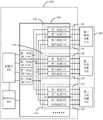
请参阅图1,本发明提供一种阻抗量测系统1000,用以测量产品300的导电引脚之间的阻抗。所述阻抗量测系统1000至少包括:继电器板100与测量仪200。Please refer to FIG. 1 , the present invention provides an
所述继电器板100包括若干继电器组110。每一所述继电器组110包括第一通道121、第二通道122、第三通道131及第四通道132。所述继电器板100还包括第一电压接口140、第二电压接口160、第一电流接口150及第二电流接口170。所述第一电压接口140与第一电流接口150为正极接口,所述第二电压接口160与第二电流接口170为负极接口。The
所述第一电压接口140与所述第一通道121电连接。所述第一电流接口150与所述第二通道122电连接。所述第二电压接口160与所述第三通道131电连接。所述第二电流接口170与所述第四通道132电连接。The first voltage interface 140 is electrically connected to the first channel 121 . The first current interface 150 is electrically connected to the second channel 122 . The second voltage interface 160 is electrically connected to the third channel 131 . The second current interface 170 is electrically connected to the fourth channel 132 .
所述测量仪200用于测量阻抗。所述第一电压接口140、第二电压接口160、第一电流接口150及第二电流接口170均电连接于所述测量仪200。具体的,所述测量仪200是可以测量电阻、电容、电感等参数的仪器,例如可以是阻抗分析仪。The measuring
可以理解,为描述方便,本实施方式中,以产品300包括三个导电引脚(例如第一导电引脚310、第二导电引脚320及第三导电引脚330)为例详细说明阻抗量测系统1000的工作原理。在实际测量时,所述继电器组110的数量应当大于等于产品300的导电引脚的总数。It can be understood that, for the convenience of description, in this embodiment, the
当测试时,所述第一导电引脚310、第二导电引脚320及第三导电引脚330均各自电连接于一个所述继电器组110,例如电连接至该继电器组110的所述第一通道121、第二通道122、第三通道131及第四通道132。When testing, the first
可以理解,通过设置具有多通道的继电器组110,并将每一继电器组110与产品300的一个导电引脚电连接,可通过使得每一个继电器组110的通道的打开与关闭,以独立控制对应的导电引脚是否接入阻抗测量的回路。如此,有效避免了反复的在产品300不同的导电引脚之间切换接线,提高了测量效率,降低了测量错误的可能性。It can be understood that by setting the
在本实施方式中,每一所述继电器组110包括奇数继电器120与偶数继电器130。所述第一通道121与所述第二通道122构成所述奇数继电器120,所述第三通道131与所述第四通道132构成所述偶数继电器130。In this embodiment, each of the
请继续参阅图1,所述阻抗量测系统1000还包括控制单元500,用于控制所述继电器板100切换通道。所述控制单元500的一端与所述继电器板100电连接,另一端与所述测量仪200电连接。所述控制单元500,例如可以是具有以上控制功能的计算机、工控机等。控制单元500在每次切换时只控制打开与待测的两个导电引脚相电连接的两个所述继电器组110的通道,而关闭其他所述继电器组110的通道,并且每一次测量时只打开其中一个所述继电器组110的所述奇数继电器120与另一个所述继电器组110的所述偶数继电器130。Please continue to refer to FIG. 1 , the
可以理解,通过所述控制单元500每次切换只打开与待测的两个导电引脚相电连接的两个所述继电器组110的通道,而关闭其他所述继电器组110的通道,可以根据测量需要每次将不同的两个导电引脚接入到阻抗测量的回路。通过多次切换即可实现测量所有导电引脚两两之间的阻抗。It can be understood that by switching the
请继续参阅图1,当在所述第一导电引脚310与所述第二导电引脚320之间进行阻抗测量时,所述控制单元500切换两次通道。第一次切换时,所述控制单元500控制打开与所述第一导电引脚310电连接的所述继电器组110的所述奇数继电器120,同时打开与所述第二导电引脚320电连接的所述继电器组110的偶数继电器130,而关闭与所述第一导电引脚310电连接的所述继电器组110的所述偶数继电器130及与所述第二导电引脚320电连接的所述继电器组110的所述奇数继电器120。如此,所述第一电压接口140、与第一导电引脚310电连接的第一通道121、第一导电引脚310、第二导电引脚320、与第二导电引脚320电连接的第三通道131及第二电压接口160形成第一回路,以测量第一导电引脚310与第二导电引脚320之间的电压。同时,所述第一电流接口150、与第一导电引脚310电连接的第二通道122、第一导电引脚310、第二导电引脚320、第二导电引脚320电连接的第四通道132及第二电流接口170形成第二回路,以供给第一导电引脚310与第二导电引脚320之间的测试电流,所述测试电流为测量仪200所提供。如此根据第一回路测得的电压及所述测试电流(用测得的电压除以所述测试电流),即可得到第一导电引脚310到第二导电引脚320之间的阻抗。Please continue to refer to FIG. 1 , when impedance measurement is performed between the first
第二次切换时,所述控制单元500控制打开与所述第一导电引脚310电连接的所述继电器组110的所述偶数继电器130,同时打开与所述第二导电引脚320电连接的所述继电器组110的奇数继电器120,而关闭与第一导电引脚310电连接的所述继电器组110的奇数继电器120及与第二导电引脚320电连接的所述继电器组110的偶数继电器130。如此,所述第一电压接口140、与第二导电引脚320电连接的第一通道121、第二导电引脚320、第一导电引脚310、与第一导电引脚310电连接的第三通道131及第二电压接口160形成第一回路,以测量第一导电引脚310与第二导电引脚320之间的电压。所述第一电流接口150、与第二导电引脚320电连接的第二通道122、第二导电引脚320、第一导电引脚310、第二导电引脚320电连接的第四通道132及第二电流接口170形成第二回路以供给第一导电引脚310与第二导电引脚320之间的测试电流,所述测试电流为测量仪200所提供。根据第一回路测得的电压及所述测试电流(测得的电压除以所述测试电流),即可得到第二导电引脚320到第一导电引脚310之间的阻抗。When switching for the second time, the
可以理解,上述第一种接法(第一次切换的电路接法)与第二种接法(第二次切换的电路接法)并没有严格的先后顺序之分,在另一实施方式中,可以将两种接法的顺序进行对调。It can be understood that there is no strict sequence between the first connection method (circuit connection method of the first switch) and the second connection method (circuit connection method of the second switch). In another embodiment , the order of the two connection methods can be reversed.
同上,在所述第一导电引脚310与所述第三导电引脚330之间进行阻抗测量时,所述控制单元500依然切换两次通道,具体过程和上述第一导电引脚310与所述第三导电引脚330之间进行阻抗测量类似,此处不再赘述。As above, when the impedance measurement is performed between the first
可以理解,如果两个所述导电引脚之间包含例如二极管、三极管及MOS管等器件,那么在测量阻抗时,由于这些器件均具有单向导电性,如上文所述第一次切换和第二次切换所示进行两次电路连接所测得的阻抗值是不一样的,所以有必要进行两次测量。例如测量第一导电引脚310和第二导电引脚320时,第一次接时将测量仪200的正极接到第一导电引脚310,将负极接到第二导电引脚320,第二次接时将测量仪200的正极接到第二导电引脚320,将负极接到第一导电引脚310。可以理解,两次的接法的顺序也可以交换。由于所述继电器组110的所述奇数继电器120与所述正极(即与所述第一电压接口140和所述第一电流接口150)电连接,所述继电器组110的所述偶数继电器130与所述负极(即与所述第二电压接口160和所述第二电流接口170)电连接。如此,通过所述控制单元500对所述奇数继电器120与偶数继电器130的打开与关闭,即可实现以两种正负极不同的接法测量两次每两个所述导电引脚之间的阻抗。It can be understood that if devices such as diodes, triodes and MOS tubes are included between the two conductive pins, when measuring impedance, since these devices have unidirectional conductivity, as mentioned above, the first switching and the second switching The impedance values measured by the two circuit connections shown in the second switching are different, so it is necessary to perform two measurements. For example, when measuring the first
可以理解,如果两个所述导电引脚之间不包含例如二极管、三极管及MOS管等器件,那么在测量阻抗时,上文第一次切换和第二次切换测得的阻抗值是一样的。It can be understood that if there are no devices such as diodes, triodes, and MOS tubes between the two conductive pins, then when measuring impedance, the impedance values measured by the first switching and the second switching above are the same .
请参阅图2,在一具体实施方式中,所述阻抗量测系统1000还包括转接板400。转接板400电连接于所述继电器板100与所述产品300之间。所述转接板400具有若干个引脚插口410。所述引脚插口410的数量大于等于所述产品300的导电引脚的数量。例如,在本实施方式中,所述转接板400具有三个所述引脚插口410,分别用于收容所述产品300的所述第一导电引脚310、第二导电引脚320及第三导电引脚330。每一所述引脚插口410均各自电连接于一个所述继电器组110,例如电连接至该继电器组110的所述第一通道121、第二通道122、第三通道131及第四通道132。Please refer to FIG. 2 , in a specific implementation manner, the
可以理解,由于在测量时需要将所述产品的每一导电引脚同时接到与其对应的所述第一通道121、第二通道122、第三通道131及第四通道132,所述转接板400的设置使得在测量时,每一导电引脚只需要电连接于一个所述引脚插口410,从而方便了接线。It can be understood that since each conductive pin of the product needs to be connected to the first channel 121, the second channel 122, the third channel 131 and the fourth channel 132 corresponding to it at the same time during the measurement, the switching The
在本实施方式中,所述导电引脚的数量为n,且n为大于等于2的正整数。所述控制单元500要进行n*(n-1)次的通道切换,经过测量并记录后得到n*(n-1)个阻抗数据。In this implementation manner, the number of the conductive pins is n, and n is a positive integer greater than or equal to 2. The
请参阅图3,在一具体实施方式中,所述阻抗量测系统1000还包括显示单元600,用于显示测得的阻抗数据。所述显示单元600电连接于所述控制单元500。Please refer to FIG. 3 , in a specific implementation manner, the
请参阅图4,图4为通过所述阻抗量测系统1000测得的阻抗数据的示意图。所述阻抗数据可显示于所述显示单元600上。如图4所示,横轴显示的是接正极的所述导电引脚,所述正极例如是第一电压接口140和第一电流接口150。纵轴显示的是接负极的所述导电引脚,所述负极例如是第二电压接口160和第二电流接口170。由于所述量测系统是测量两个所述导电引脚之间的阻抗,所以无需将正极和负极接到同一个导电引脚上,因此图4中对角线上的数据是缺省的。通过设置显示单元600,实现了对阻抗数据的显示。Please refer to FIG. 4 , which is a schematic diagram of impedance data measured by the
在一具体实施方式中,所述阻抗量测系统1000还包括固定机构(图未示),用于固定所述继电器板100及所述转接板400,使得在测量阻抗过程中继电器板100始终处于稳定状态,避免因接口接触不稳定而造成的测量错误。In a specific embodiment, the
最后应说明的是,以上实施方式仅用以说明本发明的技术方案而非限制,尽管参照较佳实施方式对本发明进行了详细说明,本领域的普通技术人员应当理解,可以对本发明的技术方案进行修改或等同替换,而不脱离本发明技术方案的精神和范围。Finally, it should be noted that the above embodiments are only used to illustrate the technical solutions of the present invention and not to limit them. Although the present invention has been described in detail with reference to preferred embodiments, those skilled in the art should understand that the technical solutions of the present invention can be Modifications or equivalent replacements can be made without departing from the spirit and scope of the technical solutions of the present invention.
Claims (10)
Priority Applications (3)
| Application Number | Priority Date | Filing Date | Title |
|---|---|---|---|
| CN202110808938.6ACN115616440B (en) | 2021-07-16 | 2021-07-16 | Impedance measurement system |
| TW110132348ATWI799974B (en) | 2021-07-16 | 2021-08-31 | Impedance measurement system |
| US17/546,372US11624763B2 (en) | 2021-07-16 | 2021-12-09 | Error-tolerant system for measuring impedance |
Applications Claiming Priority (1)
| Application Number | Priority Date | Filing Date | Title |
|---|---|---|---|
| CN202110808938.6ACN115616440B (en) | 2021-07-16 | 2021-07-16 | Impedance measurement system |
Publications (2)
| Publication Number | Publication Date |
|---|---|
| CN115616440Atrue CN115616440A (en) | 2023-01-17 |
| CN115616440B CN115616440B (en) | 2025-10-03 |
Family
ID=84854609
Family Applications (1)
| Application Number | Title | Priority Date | Filing Date |
|---|---|---|---|
| CN202110808938.6AActiveCN115616440B (en) | 2021-07-16 | 2021-07-16 | Impedance measurement system |
Country Status (3)
| Country | Link |
|---|---|
| US (1) | US11624763B2 (en) |
| CN (1) | CN115616440B (en) |
| TW (1) | TWI799974B (en) |
Families Citing this family (2)
| Publication number | Priority date | Publication date | Assignee | Title |
|---|---|---|---|---|
| FR3115116B1 (en)* | 2020-10-09 | 2022-11-11 | Saipem Sa | Method for determining the linear electrical resistance in alternating regime of a steel pipe and device for implementing such a method |
| CN119269890B (en)* | 2024-10-16 | 2025-05-27 | 广州诺顶智能科技有限公司 | A multi-pin chip capacitor testing device and system |
Citations (10)
| Publication number | Priority date | Publication date | Assignee | Title |
|---|---|---|---|---|
| RU2002115596A (en)* | 2002-06-11 | 2004-02-10 | Российский федеральный дерный центр - Всероссийский научно-исследовательский институт эксперементальной физики | Multichannel Resistance Meter |
| CN101162244A (en)* | 2007-11-21 | 2008-04-16 | 中国船舶重工集团公司第七一二研究所 | Train insulating resistance testing recorder and testing method |
| CN101726667A (en)* | 2009-12-18 | 2010-06-09 | 湖南南车时代电动汽车股份有限公司 | Insulation detecting method and device for electric automobile |
| CN202676841U (en)* | 2012-05-31 | 2013-01-16 | 佰电科技(苏州)有限公司 | Short circuit test structure for adjacent pins of connector |
| WO2016045001A1 (en)* | 2014-09-23 | 2016-03-31 | Dialog Semiconductor Inc. | Usb data pin impedance detection |
| US20170138998A1 (en)* | 2015-11-16 | 2017-05-18 | Mediatek Inc. | Testing Device for Connection Interface and Related Testing Methods |
| CN107991535A (en)* | 2017-12-01 | 2018-05-04 | 中国兵器装备集团自动化研究所 | Multichannel insulate and conducting resistance measuring system and its passageway switching method |
| TW201829993A (en)* | 2016-11-01 | 2018-08-16 | 英商伊門勒汀斯有限公司 | Resistance measurement and current control |
| CN211697979U (en)* | 2019-12-12 | 2020-10-16 | 上海元城汽车技术有限公司 | Test apparatus and test system |
| CN213302369U (en)* | 2021-03-26 | 2021-05-28 | 敏业信息科技(上海)有限公司 | Insertion loss test tool and test device |
Family Cites Families (6)
| Publication number | Priority date | Publication date | Assignee | Title |
|---|---|---|---|---|
| DE2247746C3 (en)* | 1972-09-29 | 1975-11-27 | Siemens Ag, 1000 Berlin Und 8000 Muenchen | Method of measuring a line impedance |
| TWI281985B (en)* | 2004-12-22 | 2007-06-01 | Inventec Corp | System and method for resistance measuring |
| TWI308217B (en)* | 2006-12-05 | 2009-04-01 | Inventec Corp | Contant-temperature and constant-humidity type automated resistant testing system |
| US7872377B2 (en)* | 2009-01-15 | 2011-01-18 | Wilson Phillip C | Communications in multiple-switch electrical circuits |
| KR101636112B1 (en)* | 2013-05-03 | 2016-07-04 | 주식회사 엘지화학 | Apparatus and method of measuring impedance of battery |
| CN206945826U (en)* | 2017-08-01 | 2018-01-30 | 成都天大仪器设备有限公司 | Electric impedance analyzer |
- 2021
- 2021-07-16CNCN202110808938.6Apatent/CN115616440B/enactiveActive
- 2021-08-31TWTW110132348Apatent/TWI799974B/enactive
- 2021-12-09USUS17/546,372patent/US11624763B2/enactiveActive
Patent Citations (10)
| Publication number | Priority date | Publication date | Assignee | Title |
|---|---|---|---|---|
| RU2002115596A (en)* | 2002-06-11 | 2004-02-10 | Российский федеральный дерный центр - Всероссийский научно-исследовательский институт эксперементальной физики | Multichannel Resistance Meter |
| CN101162244A (en)* | 2007-11-21 | 2008-04-16 | 中国船舶重工集团公司第七一二研究所 | Train insulating resistance testing recorder and testing method |
| CN101726667A (en)* | 2009-12-18 | 2010-06-09 | 湖南南车时代电动汽车股份有限公司 | Insulation detecting method and device for electric automobile |
| CN202676841U (en)* | 2012-05-31 | 2013-01-16 | 佰电科技(苏州)有限公司 | Short circuit test structure for adjacent pins of connector |
| WO2016045001A1 (en)* | 2014-09-23 | 2016-03-31 | Dialog Semiconductor Inc. | Usb data pin impedance detection |
| US20170138998A1 (en)* | 2015-11-16 | 2017-05-18 | Mediatek Inc. | Testing Device for Connection Interface and Related Testing Methods |
| TW201829993A (en)* | 2016-11-01 | 2018-08-16 | 英商伊門勒汀斯有限公司 | Resistance measurement and current control |
| CN107991535A (en)* | 2017-12-01 | 2018-05-04 | 中国兵器装备集团自动化研究所 | Multichannel insulate and conducting resistance measuring system and its passageway switching method |
| CN211697979U (en)* | 2019-12-12 | 2020-10-16 | 上海元城汽车技术有限公司 | Test apparatus and test system |
| CN213302369U (en)* | 2021-03-26 | 2021-05-28 | 敏业信息科技(上海)有限公司 | Insertion loss test tool and test device |
Also Published As
| Publication number | Publication date |
|---|---|
| CN115616440B (en) | 2025-10-03 |
| US20230012533A1 (en) | 2023-01-19 |
| US11624763B2 (en) | 2023-04-11 |
| TW202305381A (en) | 2023-02-01 |
| TWI799974B (en) | 2023-04-21 |
Similar Documents
| Publication | Publication Date | Title |
|---|---|---|
| US7262626B2 (en) | Connection apparatus and cable assembly for semiconductor-device characteristic measurement apparatus | |
| CN104569730A (en) | Cable testing system applied to minisatellite | |
| US7388366B2 (en) | Test system connection system with triaxial cables | |
| US20120242357A1 (en) | Automatic fault insertion, calibration and test system | |
| CN115616440B (en) | Impedance measurement system | |
| CN106199091A (en) | Electrical functions test device, system and method | |
| CN210604939U (en) | Wire harness testing device | |
| US20070296401A1 (en) | Interleaved Differential Multiplexer | |
| CN207924050U (en) | The epitaxial apparatus of the inspection of capacitance batch and test | |
| CN206020563U (en) | Signal adapting device and the fault diagnosis system including signal adapting device | |
| CN115032520A (en) | An automated remote measurement and control system for testing power management chips | |
| CN106291267A (en) | The electrical property test instrument of spacecraft thermal test multicore cable | |
| CN105510757A (en) | A triaxial DC-AC connection system | |
| CN202196145U (en) | Cable insulation voltage-withstanding test tool | |
| CN104459426A (en) | Cable detection system | |
| CN201780338U (en) | Wire-to-wire capacitance testing device | |
| CN102081120A (en) | Testing system | |
| CN115128406A (en) | Withstand voltage test device | |
| JPH11190760A (en) | Semiconductor test apparatus | |
| CN106053985B (en) | A kind of Power over Ethernet test device | |
| CN112240949A (en) | Test apparatus and control method thereof | |
| CN218767165U (en) | Automatic testing arrangement of batch electron device | |
| RU158297U1 (en) | AUTOMATED DEVICE FOR FUNCTIONAL MONITORING AND MONITORING OF PARAMETERS OF ELECTRIC CIRCUITS OF COMPLEX TECHNICAL PRODUCTS | |
| CN217404452U (en) | Discharge testing device | |
| CN221078841U (en) | Multi-parameter comprehensive automatic testing equipment for multi-core digital products |
Legal Events
| Date | Code | Title | Description |
|---|---|---|---|
| PB01 | Publication | ||
| PB01 | Publication | ||
| SE01 | Entry into force of request for substantive examination | ||
| SE01 | Entry into force of request for substantive examination | ||
| GR01 | Patent grant |