CN115611138A - rope connection device - Google Patents
rope connection deviceDownload PDFInfo
- Publication number
- CN115611138A CN115611138ACN202110802650.8ACN202110802650ACN115611138ACN 115611138 ACN115611138 ACN 115611138ACN 202110802650 ACN202110802650 ACN 202110802650ACN 115611138 ACN115611138 ACN 115611138A
- Authority
- CN
- China
- Prior art keywords
- buckle
- hook
- handshake
- rope
- assembly
- Prior art date
- Legal status (The legal status is an assumption and is not a legal conclusion. Google has not performed a legal analysis and makes no representation as to the accuracy of the status listed.)
- Granted
Links
Images


Classifications
- B—PERFORMING OPERATIONS; TRANSPORTING
- B66—HOISTING; LIFTING; HAULING
- B66C—CRANES; LOAD-ENGAGING ELEMENTS OR DEVICES FOR CRANES, CAPSTANS, WINCHES, OR TACKLES
- B66C1/00—Load-engaging elements or devices attached to lifting or lowering gear of cranes or adapted for connection therewith for transmitting lifting forces to articles or groups of articles
- B66C1/10—Load-engaging elements or devices attached to lifting or lowering gear of cranes or adapted for connection therewith for transmitting lifting forces to articles or groups of articles by mechanical means
- B66C1/22—Rigid members, e.g. L-shaped members, with parts engaging the under surface of the loads; Crane hooks
- B66C1/34—Crane hooks
- B—PERFORMING OPERATIONS; TRANSPORTING
- B66—HOISTING; LIFTING; HAULING
- B66C—CRANES; LOAD-ENGAGING ELEMENTS OR DEVICES FOR CRANES, CAPSTANS, WINCHES, OR TACKLES
- B66C1/00—Load-engaging elements or devices attached to lifting or lowering gear of cranes or adapted for connection therewith for transmitting lifting forces to articles or groups of articles
- B66C1/10—Load-engaging elements or devices attached to lifting or lowering gear of cranes or adapted for connection therewith for transmitting lifting forces to articles or groups of articles by mechanical means
- B66C1/12—Slings comprising chains, wires, ropes, or bands; Nets
- B—PERFORMING OPERATIONS; TRANSPORTING
- B66—HOISTING; LIFTING; HAULING
- B66C—CRANES; LOAD-ENGAGING ELEMENTS OR DEVICES FOR CRANES, CAPSTANS, WINCHES, OR TACKLES
- B66C1/00—Load-engaging elements or devices attached to lifting or lowering gear of cranes or adapted for connection therewith for transmitting lifting forces to articles or groups of articles
- B66C1/10—Load-engaging elements or devices attached to lifting or lowering gear of cranes or adapted for connection therewith for transmitting lifting forces to articles or groups of articles by mechanical means
- B66C1/22—Rigid members, e.g. L-shaped members, with parts engaging the under surface of the loads; Crane hooks
- B66C1/34—Crane hooks
- B66C1/36—Crane hooks with means, e.g. spring-biased detents, for preventing inadvertent disengagement of loads
- F—MECHANICAL ENGINEERING; LIGHTING; HEATING; WEAPONS; BLASTING
- F16—ENGINEERING ELEMENTS AND UNITS; GENERAL MEASURES FOR PRODUCING AND MAINTAINING EFFECTIVE FUNCTIONING OF MACHINES OR INSTALLATIONS; THERMAL INSULATION IN GENERAL
- F16G—BELTS, CABLES, OR ROPES, PREDOMINANTLY USED FOR DRIVING PURPOSES; CHAINS; FITTINGS PREDOMINANTLY USED THEREFOR
- F16G11/00—Means for fastening cables or ropes to one another or to other objects; Caps or sleeves for fixing on cables or ropes
- F16G11/14—Devices or coupling-pieces designed for easy formation of adjustable loops, e.g. choker hooks; Hooks or eyes with integral parts designed to facilitate quick attachment to cables or ropes at any point, e.g. by forming loops
- F16G11/143—Hooks
Landscapes
- Engineering & Computer Science (AREA)
- Mechanical Engineering (AREA)
- General Engineering & Computer Science (AREA)
- Emergency Lowering Means (AREA)
Abstract
Translated fromChinese
Description
Translated fromChinese技术领域technical field
本发明属于船舶航标技术领域,尤其涉及绳索连接装置。The invention belongs to the technical field of navigation aids for ships, and in particular relates to a rope connection device.
背景技术Background technique
航标吊换吊检作业时,船舶吊机的吊钩与航标的吊耳需通过钢丝绳连接,在进行作业时,首先需要将吊标钢丝绳穿过航标吊耳。船上的操作人员与水中的航标距离较远,吊标钢丝绳较粗较重且有较大韧性,因此将钢丝绳直接穿过航标吊耳难度较大。为将钢丝绳穿过航标吊耳,船员在作业中一般先将钢丝绳与较为轻便的引绳连接,再将引绳穿过吊耳,最后通过引绳将吊标钢丝绳拉入吊耳。When the navigation mark is changed and inspected, the hook of the ship crane and the lifting lug of the navigation mark need to be connected by a wire rope. The operator on the ship is far away from the buoy in the water, and the buoy wire rope is thick, heavy and has great toughness, so it is difficult to pass the wire rope directly through the buoy lug. In order to pass the steel wire rope through the buoy lug, the crew usually connects the steel wire rope with a lighter lead rope during operation, then passes the lead rope through the lug, and finally pulls the buoy wire rope into the lug through the lead rope.
引绳穿过吊耳需人工先将一部分引绳远距离抛投在吊耳上合适的位置,才能进行钩绳以及拉绳等操作步骤。人工远距离抛投引绳的准确率较低,尤其在目标是干舷较高的大标船或者大风浪环境作业时,通常需要至少抛投2至3次才能将引绳抛投成功。另外吊耳穿绳作业通常需要两个人配合完成,这样不仅降低了作业效率以及提高了人工成本,还增加了舷边作业的安全风险。When the guide rope passes through the lifting lug, it is necessary to manually throw a part of the guide rope at a suitable position on the lifting lug for a long distance before performing operations such as hooking the rope and pulling the rope. The accuracy of manual long-distance throwing of the lead rope is low, especially when the target is a large ship with a high freeboard or operating in a stormy environment, it usually takes at least 2 to 3 throws to successfully throw the lead rope. In addition, the rope threading operation of the lifting lug usually requires the cooperation of two people, which not only reduces the operation efficiency and increases the labor cost, but also increases the safety risk of the side operation.
因此,亟需一种高效率的引绳穿入吊耳的技术方案。Therefore, there is an urgent need for a high-efficiency technical solution for leading ropes to be inserted into lifting lugs.
发明内容Contents of the invention
本发明的目的在于:针对现有技术的不足,而提供绳索连接装置,以解决现有人工抛投引绳穿入吊耳中效率过低的问题。The object of the present invention is to provide a rope connection device for the deficiencies of the prior art, so as to solve the problem of low efficiency of the existing manual throwing guide ropes in the lifting lugs.
为了实现上述目的,本发明采用以下技术方案:In order to achieve the above object, the present invention adopts the following technical solutions:
绳索连接装置,包括吊钩组件、绳索卡扣组件以及握手组件,所述吊钩组件包括上钩件、下钩件以及吊钩连接件,所述吊钩连接件上设置有转动部,所述绳索卡扣组件包括上卡扣件以及与所述上卡扣件相应的下卡扣件,所述上卡扣件设置有上绳索连接部,所述下卡扣件设置有下绳索连接部,所述握手组件包括握手部以及传动部;所述上钩件的第一端在侧面通过所述上限位件设置有所述上卡扣件,所述上钩件的第一端具有上钩端面,所述上钩件的第一端内部设置有上限位件,所述上钩端面上设置有向其内部延伸且供所述上限位件做往复运动的上限位槽,所述上限位件具有上扣合部,所述上限位件的第一端为上限位凸部,所述上限位凸部沿所述上限位槽从所述上钩端面凸出时所述上扣合部将所述上卡扣件扣合,所述上限位凸部沿所述上限位槽进入所述上限位槽的内部时所述上扣合部与所述上卡扣件脱离;所述上钩件的第二端与所述吊钩连接件的第一端连接;所述下钩件的第一端在侧面通过所述下限位件设置有所述下卡扣件,所述下钩件的第一端具有下钩端面,所述下钩件的第一端内部设置有下限位件,所述下钩端面上设置有向其内部延伸且供所述下限位件做往复运动的下限位槽,所述下限位件具有下扣合部,所述下限位件的第一端为下限位凸部,所述下限位凸部沿所述下限位槽从所述下钩端面凸出时所述下扣合部将所述下卡扣件扣合,所述下限位凸部沿所述下限位槽进入所述下限位槽的内部时所述下扣合部与所述下卡扣件脱离;所述下钩件的第二端与所述转动部转动连接,所述下钩件的第二端与所述传动部传动连接;所述下钩件通过绕所述转动部转动使所述下卡扣件与所述上卡扣件卡扣连接;所述下钩件通过绕所述转动部转动使所述上限位凸部与所述下钩端面接触配合,同时使所述下限位凸部与所述上钩端面接触配合。The rope connection device includes a hook assembly, a rope buckle assembly and a handshake assembly. The hook assembly includes an upper hook, a lower hook, and a hook connector. The hook connector is provided with a rotating part. The rope The buckle assembly includes an upper buckle part and a lower buckle part corresponding to the upper buckle part, the upper buckle part is provided with an upper rope connection part, and the lower buckle part is provided with a lower rope connection part, so The handshake assembly includes a handshake part and a transmission part; the first end of the upper hook part is provided with the upper buckle part through the upper limit part on the side, the first end of the upper hook part has a hook end surface, and the upper hook An upper limit member is provided inside the first end of the member, and an upper limit groove extending to the inside of the upper hook end surface for the reciprocating movement of the upper limit member is provided. The upper limit member has an upper buckle part, so The first end of the upper limit member is an upper limit protrusion, and when the upper limit protrusion protrudes from the end surface of the upper hook along the upper limit groove, the upper buckle engages the upper buckle, When the upper limit protrusion enters the upper limit groove along the upper limit groove, the upper fastening part is disengaged from the upper buckle; the second end of the upper hook is connected to the hook The first end of the lower hook is connected to the first end of the lower hook on the side through the lower stopper is provided with the lower buckle, the first end of the lower hook has a lower hook end surface, the lower A lower limiter is provided inside the first end of the hook, and a lower limit groove extending to the inside of the lower hook end surface for the reciprocating movement of the lower limiter is provided, and the lower limiter has a lower fastening portion , the first end of the lower limiting member is a lower limiting convex portion, and when the lower limiting convex portion protrudes from the end surface of the lower hook along the lower limiting groove, the lower buckling portion will hold the lower locking member fastening, when the lower limiting protrusion enters the interior of the lower limiting groove along the lower limiting groove, the lower buckling part is disengaged from the lower buckle; the second end of the lower hook is in contact with the lower hook The rotating part is rotatably connected, and the second end of the lower hook is connected to the transmission part in transmission; the lower hook rotates around the rotating part so that the lower buckle and the upper buckle are engaged. Buckle connection; the lower hook rotates around the rotating part to make the upper limit convex part contact and cooperate with the end surface of the lower hook, and at the same time make the lower limit convex part contact and cooperate with the upper hook end surface.
作为本发明所述的绳索连接装置的优选方案,所述上扣合部与所述上卡扣件扣合时,所述上卡扣件的端面从所述上钩端面凸出,所述上钩件的第一端在侧面具有第一上导向斜坡,所述上卡扣件沿所述第一上导向斜坡与所述上扣合部脱离。As a preferred solution of the rope connection device according to the present invention, when the upper buckle part is fastened with the upper buckle part, the end surface of the upper buckle part protrudes from the upper hook end surface, and the upper hook part The first end of the first end has a first upper guide slope on the side, and the upper buckle part is disengaged from the upper buckle part along the first upper guide slope.
作为本发明所述的绳索连接装置的优选方案,所述下扣合部与所述下卡扣件扣合时,所述下卡扣件的端面从所述上钩端面凸出,所述下钩件的第一端在侧面具有第一下导向斜坡,所述下卡扣件沿所述第一下导向斜坡与所述下扣合部脱离。As a preferred solution of the rope connection device according to the present invention, when the lower fastening part is fastened with the lower buckle, the end surface of the lower buckle protrudes from the end surface of the upper hook, and the lower hook The first end of the part has a first lower guiding slope on the side, and the lower buckling part is disengaged from the lower buckling part along the first lower guiding slope.
作为本发明所述的绳索连接装置的优选方案,所述上扣合部具有与所述第一上导向斜坡相应的第二上导向斜坡,所述上卡扣件依次沿所述第一上导向斜坡以及所述第二上导向斜坡与所述上扣合部脱离。As a preferred solution of the rope connection device according to the present invention, the upper buckle part has a second upper guide slope corresponding to the first upper guide slope, and the upper buckle is sequentially guided along the first upper guide slope. The slope and the second upper guiding slope are disengaged from the upper buckling portion.
作为本发明所述的绳索连接装置的优选方案,所述下扣合部具有与所述第一下导向斜坡相应的第二下导向斜坡,所述下卡扣件依次沿所述第一下导向斜坡以及所述第二下导向斜坡与所述下扣合部脱离。As a preferred solution of the rope connection device of the present invention, the lower buckling part has a second lower guide slope corresponding to the first lower guide slope, and the lower buckle is sequentially guided along the first lower guide slope. The slope and the second lower guiding slope are disengaged from the lower engaging portion.
作为本发明所述的绳索连接装置的优选方案,所述上卡扣件设置有上卡扣插孔以及上卡扣夹,所述上卡扣夹的第一端设置有上卡扣钩且伸入所述上卡扣插孔内,所述上卡扣夹的第二端与所述上卡扣件转动连接,所述下卡扣件设置有与所述上卡扣插孔对应的下卡扣插件,所述下卡扣插件上设置有与所述上卡扣钩相应的下限位钩槽;所述下钩件通过绕所述转动部转动使所述上卡扣钩与所述下限位钩槽卡扣连接;或者所述下卡扣件设置有下卡扣插孔以及下卡扣夹,所述下卡扣夹的第一端设置有下卡扣钩且伸入所述下卡扣插孔内,所述下卡扣夹的第二端与所述下卡扣件转动连接,所述上卡扣件设置有与所述下卡扣插孔对应的上卡扣插件,所述上卡扣插件上设置有与所述下卡扣钩相应的上限位钩槽;所述下钩件通过绕所述转动部转动使所述下卡扣钩与所述上限位钩槽卡扣连接。As a preferred solution of the rope connection device according to the present invention, the upper buckle member is provided with an upper buckle socket and an upper buckle clip, and the first end of the upper buckle clip is provided with an upper buckle hook and extends into the upper buckle jack, the second end of the upper buckle clip is rotatably connected to the upper buckle piece, and the lower buckle piece is provided with a lower buckle corresponding to the upper buckle jack Buckle plug-in, the lower snap-in plug-in is provided with the lower limit hook slot corresponding to the upper snap hook; the lower hook rotates around the rotating part so that the upper snap hook and the lower limit Hook groove buckle connection; or the lower buckle part is provided with a lower buckle socket and a lower buckle clip, and the first end of the lower buckle clip is provided with a lower buckle hook and extends into the lower buckle In the socket, the second end of the lower buckle clip is rotatably connected to the lower buckle member, and the upper buckle member is provided with an upper buckle insert corresponding to the lower buckle socket, and the upper buckle The buckle insert is provided with an upper limit hook slot corresponding to the lower buckle hook; the lower hook part rotates around the rotating part to make the lower buckle hook snap into connection with the upper limit hook groove.
作为本发明所述的绳索连接装置的优选方案,所述上钩件第一端在两侧分别设置有上接触导向件,所述上卡扣件位于两侧的所述上接触导向件之间,所述下钩件第一端在两侧分别设置有下接触导向件,所述下卡扣件位于两侧的所述下接触导向件之间;所述下钩件通过绕所述转动部转动使所述上接触导向件与所述下接触导向件相互导向配合。As a preferred solution of the rope connection device according to the present invention, the first end of the upper hook member is respectively provided with upper contact guides on both sides, and the upper buckle is located between the upper contact guides on both sides, The first end of the lower hook is provided with lower contact guides on both sides, and the lower buckle is located between the lower contact guides on both sides; the lower hook rotates around the rotating part The upper contact guide and the lower contact guide are guided and matched with each other.
作为本发明所述的绳索连接装置的优选方案,所述上限位件在其第二端设置在上弹性复位件,所述下限位件在其第二端设置在下弹性复位件,所述上钩端面设置有与所述下限位凸部对应的上接触凸部,所述下钩端面设置有与所述上限位凸部对应的下接触凸部;所述下钩件通过绕所述转动部转动使所述上限位凸部与所述下接触凸部接触配合,同时使所述下限位凸部与所述上接触凸部接触配合。As a preferred solution of the rope connection device according to the present invention, the upper limit member is arranged on the upper elastic return member at its second end, the lower limit member is arranged on the lower elastic return member at its second end, and the upper hook end surface An upper contact protrusion corresponding to the lower limit protrusion is provided, and the lower hook end surface is provided with a lower contact protrusion corresponding to the upper limit protrusion; the lower hook rotates around the rotating part to make The upper limit protrusion is in contact with the lower contact protrusion, and at the same time, the lower limit protrusion is in contact with the upper contact protrusion.
作为本发明所述的绳索连接装置的优选方案,所述吊钩连接件内部设置有供所述握手组件往复运动的握手滑槽,所述握手滑槽从所述吊钩连接件的第二端向内延伸,所述传动部通过所述握手滑槽与所述下钩件的第二端传动连接,所述握手滑槽内部设置有滑槽防脱部,所述握手组件还包括与所述滑槽防脱部对应的防脱配合部,所述滑槽防脱部与所述防脱配合部相互配合以阻碍所述握手组件与所述握手滑槽脱离,所述滑槽防脱部与所述防脱配合部之间设置有滑槽弹性件。As a preferred solution of the rope connection device according to the present invention, a handshake chute for the reciprocating movement of the handshake assembly is provided inside the hook connection piece, and the handshake chute starts from the second end of the hook connection piece. Extending inward, the transmission part is in transmission connection with the second end of the lower hook through the handshake chute, a chute anti-off part is provided inside the handshake chute, and the handshake assembly also includes a The anti-off matching part corresponding to the anti-off part of the chute, the anti-off part of the chute cooperates with the anti-off part to prevent the handshake assembly from disengaging from the handshake chute, the anti-off part of the chute and the anti-off part Elastic pieces of chute are arranged between the anti-disengagement fitting parts.
作为本发明所述的绳索连接装置的优选方案,所述下钩件的第二端具有齿轮部,所述传动部为与所述齿轮部相应的传动齿条部,所述齿轮部与所述传动齿条部传动啮合。As a preferred solution of the rope connection device of the present invention, the second end of the lower hook has a gear part, and the transmission part is a transmission rack part corresponding to the gear part, and the gear part is connected to the gear part. The transmission rack portion is in transmission engagement.
本发明具有的有益效果为:本发明通过工作人员手握握手部并依次拉动握手部以及推动握手部,即可完成引绳穿过吊耳的穿绳动作,从而提高工作人员引绳穿吊耳的效率,最终提高航标作业的工作效率;同时本发明可根据实际的工作环境调节握手组件的长度,从而满足工作人员远距离穿引绳的工作要求。The beneficial effects of the present invention are as follows: in the present invention, by holding the handshake part with the staff, pulling the handshake part and pushing the handshake part in turn, the rope threading action of the guide rope passing through the lifting lug can be completed, thereby improving the staff's ability to lead the rope through the lifting lug. The efficiency is improved, and the working efficiency of the navigation mark operation is finally improved; at the same time, the present invention can adjust the length of the handshake assembly according to the actual working environment, so as to meet the working requirements of the staff for long-distance threading ropes.
附图说明Description of drawings
图1为本发明的结构示意图。Fig. 1 is a structural schematic diagram of the present invention.
图2为本发明的爆炸图。Figure 2 is an exploded view of the present invention.
图3为本发明的剖视图。Fig. 3 is a cross-sectional view of the present invention.
图4为本发明中上钩件的第一端与所述上卡扣件的装配结构图。Fig. 4 is an assembly structure diagram of the first end of the upper hook part and the upper buckle part in the present invention.
图5为本发明中上钩件的第一端与所述上卡扣件的装配剖视图。Fig. 5 is an assembly cross-sectional view of the first end of the upper hook and the upper buckle in the present invention.
图6为本发明中下钩件的第一端与所述下卡扣件的装配结构图。Fig. 6 is an assembly structure diagram of the first end of the lower hook part and the lower buckle part in the present invention.
图7为本发明中下钩件的第一端与所述下卡扣件的装配剖视图。Fig. 7 is an assembly cross-sectional view of the first end of the lower hook and the lower buckle in the present invention.
图中:In the picture:
1-吊钩组件;1-Hook assembly;
11-上钩件;11- hook piece;
111-上钩端面;1111-上接触凸部;111-upper hook end face; 1111-upper contact convex part;
112-上限位件;112-upper limit piece;
1121-上扣合部;11211-第二上导向斜坡;1122-上限位凸部;1123-上弹性复位件;1121-upper buckle; 11211-the second upper guide slope; 1122-upper limit protrusion; 1123-upper elastic reset piece;
113-上限位槽;113-upper limit slot;
114-第一上导向斜坡;114 - the first upper guide slope;
115-上接触导向件;115 - upper contact guide;
12-下钩件;12 - the lower hook;
121-下钩端面;1211-下接触凸部;121-lower hook end surface; 1211-lower contact convex part;
122-下限位件;122-lower limit piece;
1221-下扣合部;12211-第二下导向斜坡;1222-下限位凸部;1223-下弹性复位件;1221-lower fastening part; 12211-the second lower guide slope; 1222-lower limit protrusion; 1223-lower elastic reset part;
123-下限位槽;123-lower limit slot;
124-第一下导向斜坡;124 - the first lower guide ramp;
125-下接触导向件;125 - lower contact guide;
126-齿轮部;126-gear department;
13-吊钩连接件;13 - hook connector;
131-转动部;131 - rotating part;
132-握手滑槽;1321-滑槽防脱部;1322-滑槽弹性件;132-handshake chute; 1321-anti-off part of chute; 1322-elastic part of chute;
2-绳索卡扣组件;2- Rope buckle assembly;
21-上卡扣件;21 - upper card fastener;
211-上绳索连接部;211-upper rope connection part;
212-上卡扣插孔;212-upper buckle jack;
213-上卡扣夹;2131-上卡扣钩;213-upper buckle clip; 2131-upper buckle hook;
22-下卡扣件;22 - the lower card fastener;
221-下绳索连接部;221 - lower rope connection part;
222-下卡扣插件;2221-下限位钩槽;222-lower buckle plug-in; 2221-lower limit hook groove;
3-握手组件;3-handshake component;
31-握手部;31-handshake part;
32-传动部;32-transmission department;
33-防脱配合部。33-Anti-disengagement fitting part.
具体实施方式detailed description
为使本发明的技术方案和优点更加清楚,下面将结合具体实施方式和说明书附图,对本发明及其有益效果作进一步详细的描述,但本发明的实施方式不限于此。In order to make the technical solutions and advantages of the present invention clearer, the present invention and its beneficial effects will be further described in detail below in conjunction with specific embodiments and accompanying drawings, but the embodiments of the present invention are not limited thereto.
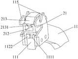
如图1至图7所示,绳索连接装置,包括吊钩组件1、绳索卡扣组件2以及握手组件3,吊钩组件1包括上钩件11、下钩件12以及吊钩连接件13,吊钩连接件13的中部设置有转动部131,绳索卡扣组件2包括上卡扣件21以及与上卡扣件21相应的下卡扣件22,上卡扣件21设置有上绳索连接部211,下卡扣件22设置有下绳索连接部221,握手组件3包括握手部31以及传动部32;上钩件11的第一端在侧面通过上限位件112设置有上卡扣件21,上钩件11的第一端具有上钩端面111,上钩件11的第一端内部设置有上限位件112,上钩端面111上设置有向其内部延伸且供上限位件112做往复运动的上限位槽113,上限位件112具有上扣合部1121,上限位件112的第一端为上限位凸部1122,上限位凸部1122沿上限位槽113从上钩端面111凸出时上扣合部1121将上卡扣件21扣合,上限位凸部1122沿上限位槽113进入上限位槽113的内部时上扣合部1121与上卡扣件21脱离;上钩件11的第二端与吊钩连接件13的第一端连接;下钩件12的第一端在侧面通过下限位件122设置有下卡扣件22,下钩件12的第一端具有下钩端面121,下钩件12的第一端内部设置有下限位件122,下钩端面121上设置有向其内部延伸且供下限位件122做往复运动的下限位槽123,下限位件122具有下扣合部1221,下限位件122的第一端为下限位凸部1222,下限位凸部1222沿下限位槽123从下钩端面121凸出时下扣合部1221将下卡扣件22扣合,下限位凸部1222沿下限位槽123进入下限位槽123的内部时下扣合部1221与下卡扣件22脱离;下钩件12的第二端与转动部131转动连接,下钩件12的第二端与传动部32传动连接;下钩件12通过绕转动部131转动使下卡扣件22与上卡扣件21卡扣连接;下钩件12通过绕转动部131转动使上限位凸部1122与下钩端面121接触配合,同时使下限位凸部1222与上钩端面111接触配合。其中,上绳索连接部211和下绳索连接部221为绳索穿孔。As shown in Figures 1 to 7, the rope connection device includes a hook assembly 1, a
本实施例的工作原理:The working principle of this embodiment:
1)首先,将引绳的一端与上绳索连接部211连接,将连接好引绳的上卡扣件21通过上扣合部1121安装在上钩件11的侧面;将引绳的另一端与下绳索连接部221连接,将连接好引绳的下卡扣件22通过下扣合部1221安装在下钩件12的侧面;1) First, connect one end of the guide rope with the upper
2)然后,工作人员用手握住握手部31,将整个绳索连接装置拿起,并将上钩件11穿入对应的航标吊耳中;2) Then, the worker holds the
3)随后,工作人员用手将握手部31向下拉动,使传动部32向下移动并带动下钩件12绕转动部131正向转动直至上钩端面111与下钩端面121接触配合,且同时使上卡扣件21与下卡扣件22接触配合且卡扣连接;此时上钩件11与下钩件12接触形成一个穿过吊耳的环形钩;3) Subsequently, the worker pulls the
4)在上钩端面111与下钩端面121接触配合的过程中:上限位件112的上限位凸部1122与下钩端面121接触配合,下钩端面121对上限位凸部1122接触的反作用力使上限位凸部1122沿上限位槽113进入上限位槽113的内部,最终使上扣合部1121与上卡扣件21脱离;同时,下限位件122的下限位凸部1222与上钩端面111接触配合,上钩端面111对下限位凸部1222接触的反作用力使下限位凸部1222沿下限位槽123进入下限位槽123的内部,最终使下扣合部1221与下卡扣件22脱离;因此,上卡扣件21与下卡扣件22在卡扣连接的同时脱离吊钩组件1;4) During the process of contacting the upper
5)最后,工作人员用手将握手部31向上推动,使传动部32向上移动并带动下钩件12绕转动部131反向转动;此时上钩件11与下钩件12具有开口,从而使吊钩组件1能脱离吊耳;绳索卡扣组件2以及引绳保留在吊耳上,完成引绳穿过吊耳的动作。5) Finally, the staff pushes the
本实施例具有的有益效果为:本实施例通过工作人员手握握手部31并依次拉动握手部31以及推动握手部31,即可完成引绳穿过吊耳的穿绳动作,从而提高工作人员引绳穿吊耳的效率,最终提高航标作业的工作效率;同时本实施例可根据实际的工作环境调节握手组件3的长度,从而满足工作人员远距离穿引绳的工作要求。The beneficial effects of this embodiment are as follows: in this embodiment, by the staff holding the
优选地,上扣合部1121与上卡扣件21扣合时,上卡扣件21的端面从上钩端面111凸出,上钩件11的第一端在侧面具有第一上导向斜坡114,上卡扣件21沿第一上导向斜坡114与上扣合部1121脱离;第一上导向斜坡114的坡度为5~85°,第一上导向斜坡114的坡度更优选为40~60°;通过上述设置,使上卡扣件21在其与下卡扣件22接触配合且卡扣连接的过程中沿第一上导向斜坡114向外侧脱离,从而实现上卡扣件21的自动脱离。Preferably, when the
优选地,下扣合部1221与下卡扣件22扣合时,下卡扣件22的端面从上钩端面111凸出,下钩件12的第一端在侧面具有第一下导向斜坡124,下卡扣件22沿第一下导向斜坡124与下扣合部1221脱离;第一下导向斜坡124的坡度为5~85°,第一下导向斜坡124的坡度更优选为40~60°。通过上述设置,使下卡扣件22在其与上卡扣件21接触配合且卡扣连接的过程中沿第一下导向斜坡124向外侧脱离,从而实现下卡扣件22的自动脱离。Preferably, when the
优选地,上扣合部1121的端面具有与第一上导向斜坡114相应的第二上导向斜坡11211,上卡扣件21依次沿第一上导向斜坡114以及第二上导向斜坡11211与上扣合部1121脱离;第二上导向斜坡11211的坡度为5~85°,第二上导向斜坡11211的坡度更优选为40~60°。通过上述设置,使上卡扣件21在其与下卡扣件22接触配合且卡扣连接的过程中依次沿第一上导向斜坡114以及第二上导向斜坡11211向外侧脱离,从而实现上卡扣件21的自动脱离,且避免上扣合部1121阻挡上卡扣件21脱离,便于上卡扣件21脱离上扣合部1121。Preferably, the end surface of the upper buckling
优选地,下扣合部1221的端面具有与第一下导向斜坡124相应的第二下导向斜坡12211,下卡扣件22依次沿第一下导向斜坡124以及第二下导向斜坡12211与下扣合部1221脱离。;第二下导向斜坡12211的坡度为5~85°,第二下导向斜坡12211的坡度更优选为40~60°。通过上述设置,使下卡扣件22在其与上卡扣件21接触配合且卡扣连接的过程中依次沿第一下导向斜坡124以及第二下导向斜坡12211向外侧脱离,从而实现下卡扣件22的自动脱离,且避免下扣合部1221阻挡下卡扣件22脱离,便于下卡扣件22脱离下扣合部1221。Preferably, the end surface of the lower buckling
优选地,上卡扣件21设置有上卡扣插孔212以及上卡扣夹213,上卡扣夹213的第一端设置有上卡扣钩2131且伸入上卡扣插孔212内,上卡扣夹213的第二端与上卡扣件21转动连接,下卡扣件22设置有与上卡扣插孔212对应的下卡扣插件222,下卡扣插件222上设置有与上卡扣钩2131相应的下限位钩槽2221;下钩件12通过绕转动部131转动使上卡扣钩2131与下限位钩槽2221卡扣连接。通过上述设置,使上卡扣件21与下卡扣件22接触配合时,下卡扣插件222插入上卡扣插孔212中并通过上卡扣钩2131与下限位钩槽2221限定,最终实现上卡扣件21与下卡扣件22的卡扣连接。当工作人员需要将上卡扣件21与下卡扣件22分离时,通过转动上卡扣夹213,使上卡扣钩2131脱离下限位钩槽2221,最终使上卡扣件21与下卡扣件22分离。Preferably, the
优选地,下卡扣件22设置有下卡扣插孔以及下卡扣夹,下卡扣夹的第一端设置有下卡扣钩且伸入下卡扣插孔内,下卡扣夹的第二端与下卡扣件22转动连接,上卡扣件21设置有与下卡扣插孔对应的上卡扣插件,上卡扣插件上设置有与下卡扣钩相应的上限位钩槽;下钩件12通过绕转动部131转动使下卡扣钩与上限位钩槽卡扣连接。通过上述设置,使上卡扣件21与下卡扣件22接触配合时,上卡扣插件插入下卡扣插孔中并通过下卡扣钩与上限位钩槽限定,最终实现上卡扣件21与下卡扣件22的卡扣连接。当工作人员需要将上卡扣件21与下卡扣件22分离时,通过转动下卡扣夹,使下卡扣钩脱离上限位钩槽,最终使上卡扣件21与下卡扣件22分离。Preferably, the
优选地,上钩件11第一端在两侧分别设置有上接触导向件115,上卡扣件21位于两侧的上接触导向件115之间,下钩件12第一端在两侧分别设置有下接触导向件125,下卡扣件22位于两侧的下接触导向件125之间;下钩件12通过绕转动部131转动使上接触导向件115与下接触导向件125相互导向配合;上接触导向件115为具有导向凹部的上接触导向板,下接触导向件125为具有与导向凹部相应的导向凸部的下接触导向板。通过上述设置,使上卡扣件21与下卡扣件22在接触前,先通过上接触导向件115与下接触导向件125导向配合,从而提高了上卡扣件21与下卡扣件22的接触准确率以及卡扣连接的成功率。Preferably, the first end of the
优选地,上限位件112在其第二端设置在上弹性复位件1123,下限位件122在其第二端设置在下弹性复位件1223,上钩端面111设置有与下限位凸部1222对应的上接触凸部1111,下钩端面121设置有与上限位凸部1122对应的下接触凸部1211;下钩件12通过绕转动部131转动使上限位凸部1122与下接触凸部1211接触配合,同时使下限位凸部1222与上接触凸部1111接触配合;上弹性复位件1123以及下弹性复位件1223为弹簧或者弹片。通过上述设置,提高了上限位凸部1122以及下限位凸部1222的接触灵敏度。Preferably, the
优选地,吊钩连接件13内部设置有供握手组件3往复运动的握手滑槽132,握手滑槽132从吊钩连接件13的第二端向内延伸,传动部32通过握手滑槽132与下钩件12的第二端传动连接,握手滑槽132内部设置有滑槽防脱部1321,握手组件3还包括与滑槽防脱部1321对应的防脱配合部33,滑槽防脱部1321与防脱配合部33相互配合以阻碍握手组件3与握手滑槽132脱离,滑槽防脱部1321与防脱配合部33之间设置有滑槽弹性件1322;滑槽弹性件1322为弹簧或者弹片。当工作人员用手将握手部31向下拉动时,防脱配合部33向滑槽防脱部1321靠近,滑槽弹性件1322被压缩;当工作人员不再向下拉动握手部31时,滑槽弹性件1322恢复原状,滑槽弹性件1322通过防脱配合部33将握手组件3向上推动使握手组件3复位。通过上述设置,实现了握手组件3与吊钩连接件13装配,且避免握手组件3与握手滑槽132脱离;同时,通过设置滑槽弹性件1322,实现了握手组件3的自动复位。Preferably, the inside of the
优选地,下钩件12的第二端具有齿轮部126,传动部32为与齿轮部126相应的传动齿条部,齿轮部126与传动齿条部传动啮合。通过上述设置,当传动齿条部向上移动时带动齿轮部126正向转动,从而使下钩件12绕转动部131正向转动;当传动齿条部向下移动时带动齿轮部126反向转动,从而使下钩件12绕转动部131反向转动。Preferably, the second end of the
根据上述说明书的揭示和教导,本发明所属领域的技术人员还能够对上述实施方式进行变更和修改。因此,本发明并不局限于上述的具体实施方式,凡是本领域技术人员在本发明的基础上所作出的任何显而易见的改进、替换或变型均属于本发明的保护范围。此外,尽管本说明书中使用了一些特定的术语,但这些术语只是为了方便说明,并不对本发明构成任何限制。According to the disclosure and teaching of the above specification, those skilled in the art to which the present invention pertains can also change and modify the above embodiment. Therefore, the present invention is not limited to the above-mentioned specific implementation manners, and any obvious improvement, substitution or modification made by those skilled in the art on the basis of the present invention shall fall within the protection scope of the present invention. In addition, although some specific terms are used in this specification, these terms are only for convenience of description and do not constitute any limitation to the present invention.
Claims (10)
Translated fromChinesePriority Applications (1)
| Application Number | Priority Date | Filing Date | Title |
|---|---|---|---|
| CN202110802650.8ACN115611138B (en) | 2021-07-15 | 2021-07-15 | Rope connection device |
Applications Claiming Priority (1)
| Application Number | Priority Date | Filing Date | Title |
|---|---|---|---|
| CN202110802650.8ACN115611138B (en) | 2021-07-15 | 2021-07-15 | Rope connection device |
Publications (2)
| Publication Number | Publication Date |
|---|---|
| CN115611138Atrue CN115611138A (en) | 2023-01-17 |
| CN115611138B CN115611138B (en) | 2025-07-11 |
Family
ID=84855412
Family Applications (1)
| Application Number | Title | Priority Date | Filing Date |
|---|---|---|---|
| CN202110802650.8AActiveCN115611138B (en) | 2021-07-15 | 2021-07-15 | Rope connection device |
Country Status (1)
| Country | Link |
|---|---|
| CN (1) | CN115611138B (en) |
Citations (5)
| Publication number | Priority date | Publication date | Assignee | Title |
|---|---|---|---|---|
| US20090064465A1 (en)* | 2006-04-17 | 2009-03-12 | Kirk Andrade | Cord Fastening System and Method |
| US20110042979A1 (en)* | 2008-04-27 | 2011-02-24 | Leon Keith Jantzen | Remotely-operated rope-threading tool |
| CN202378036U (en)* | 2011-12-23 | 2012-08-15 | 中华人民共和国天津海事局青岛航标处 | Clamping manipulator for operation of withdrawing and releasing navigation mark |
| CN106800235A (en)* | 2016-12-23 | 2017-06-06 | 中国船舶重工集团公司第七0研究所 | A kind of water surface salvages stringing device |
| CN215479186U (en)* | 2021-07-15 | 2022-01-11 | 交通运输部南海航海保障中心广州航标处 | Rope connecting device |
- 2021
- 2021-07-15CNCN202110802650.8Apatent/CN115611138B/enactiveActive
Patent Citations (5)
| Publication number | Priority date | Publication date | Assignee | Title |
|---|---|---|---|---|
| US20090064465A1 (en)* | 2006-04-17 | 2009-03-12 | Kirk Andrade | Cord Fastening System and Method |
| US20110042979A1 (en)* | 2008-04-27 | 2011-02-24 | Leon Keith Jantzen | Remotely-operated rope-threading tool |
| CN202378036U (en)* | 2011-12-23 | 2012-08-15 | 中华人民共和国天津海事局青岛航标处 | Clamping manipulator for operation of withdrawing and releasing navigation mark |
| CN106800235A (en)* | 2016-12-23 | 2017-06-06 | 中国船舶重工集团公司第七0研究所 | A kind of water surface salvages stringing device |
| CN215479186U (en)* | 2021-07-15 | 2022-01-11 | 交通运输部南海航海保障中心广州航标处 | Rope connecting device |
Also Published As
| Publication number | Publication date |
|---|---|
| CN115611138B (en) | 2025-07-11 |
Similar Documents
| Publication | Publication Date | Title |
|---|---|---|
| US11208299B2 (en) | Sling gear for single-arm operation by a remotely controlled gripper, in particular of a remotely controlled vehicle | |
| CN110416819B (en) | Push-pull locking mechanism and push-pull locking connector | |
| US20130112929A1 (en) | Chain load binder | |
| EP0089172A3 (en) | Releasable connector | |
| AU2012295460B2 (en) | Latching mechanism for a connector | |
| JP2007244543A (en) | buckle | |
| US2347718A (en) | Mooring device | |
| CN115611138A (en) | rope connection device | |
| ES8402922A1 (en) | Hose coupling | |
| CN215479186U (en) | Rope connecting device | |
| CN201953182U (en) | Remote-control seat cushion lock of electric car | |
| CN209943770U (en) | Gas circuit interface structure | |
| CN210443453U (en) | Network switch with high safety | |
| GB1058289A (en) | A hooked coupling | |
| CN215381881U (en) | Magnetic strap buckle for preventing mistaken opening | |
| CN211146621U (en) | Mounting structure of rectifying plate | |
| CN201695799U (en) | Automatic locking mechanism of lock | |
| CN212518177U (en) | Cable fixer mounting tool | |
| CN214306991U (en) | Improved generation of highlight torch presss from both sides tight unlocking device fast | |
| CN204992126U (en) | Plug assembly | |
| CN208489442U (en) | A kind of USB interface of computer dust guard | |
| CN105006672B (en) | A kind of rectangular electric connector quick locking and unlocking mechanism | |
| ATE142296T1 (en) | COUPLING DEVICE FOR CONNECTING A TOOL TO AN EXCAVATOR BOOM | |
| CN105947878B (en) | Hanger plate | |
| CN222947966U (en) | An easy-to-open and close hook and steel box girder hoisting construction device |
Legal Events
| Date | Code | Title | Description |
|---|---|---|---|
| PB01 | Publication | ||
| PB01 | Publication | ||
| SE01 | Entry into force of request for substantive examination | ||
| SE01 | Entry into force of request for substantive examination | ||
| GR01 | Patent grant | ||
| GR01 | Patent grant |