CN115609566A - A wearable interactive device for force feedback teleoperation - Google Patents
A wearable interactive device for force feedback teleoperationDownload PDFInfo
- Publication number
- CN115609566A CN115609566ACN202211350984.7ACN202211350984ACN115609566ACN 115609566 ACN115609566 ACN 115609566ACN 202211350984 ACN202211350984 ACN 202211350984ACN 115609566 ACN115609566 ACN 115609566A
- Authority
- CN
- China
- Prior art keywords
- elbow
- shoulder
- wrist
- semicircular ring
- forearm
- Prior art date
- Legal status (The legal status is an assumption and is not a legal conclusion. Google has not performed a legal analysis and makes no representation as to the accuracy of the status listed.)
- Granted
Links
- 230000002452interceptive effectEffects0.000titleclaimsabstractdescription15
- 210000000707wristAnatomy0.000claimsdescription194
- 210000000245forearmAnatomy0.000claimsdescription94
- 230000007246mechanismEffects0.000claimsdescription41
- 229910000831SteelInorganic materials0.000claimsdescription26
- 239000010959steelSubstances0.000claimsdescription26
- 230000033001locomotionEffects0.000claimsdescription9
- 230000005540biological transmissionEffects0.000claimsdescription8
- 238000005259measurementMethods0.000claimsdescription4
- 238000004804windingMethods0.000claimsdescription4
- 230000001105regulatory effectEffects0.000claims5
- 230000003993interactionEffects0.000claims4
- 230000008878couplingEffects0.000abstractdescription5
- 238000010168coupling processMethods0.000abstractdescription5
- 238000005859coupling reactionMethods0.000abstractdescription5
- 230000000875corresponding effectEffects0.000description5
- 230000009471actionEffects0.000description4
- 238000000034methodMethods0.000description4
- 241000282412HomoSpecies0.000description2
- 230000008901benefitEffects0.000description2
- 230000000694effectsEffects0.000description2
- 230000008569processEffects0.000description2
- 210000001364upper extremityAnatomy0.000description2
- 230000003190augmentative effectEffects0.000description1
- 230000009286beneficial effectEffects0.000description1
- 238000011161developmentMethods0.000description1
- 238000005516engineering processMethods0.000description1
- 210000003414extremityAnatomy0.000description1
- 238000009776industrial productionMethods0.000description1
- 238000003780insertionMethods0.000description1
- 230000037431insertionEffects0.000description1
- 238000012423maintenanceMethods0.000description1
- 238000012986modificationMethods0.000description1
- 230000004048modificationEffects0.000description1
- 230000003183myoelectrical effectEffects0.000description1
- 230000008447perceptionEffects0.000description1
- 239000013589supplementSubstances0.000description1
- 230000000007visual effectEffects0.000description1
- 230000009012visual motionEffects0.000description1
Images


Classifications
- B—PERFORMING OPERATIONS; TRANSPORTING
- B25—HAND TOOLS; PORTABLE POWER-DRIVEN TOOLS; MANIPULATORS
- B25J—MANIPULATORS; CHAMBERS PROVIDED WITH MANIPULATION DEVICES
- B25J9/00—Programme-controlled manipulators
- B25J9/0006—Exoskeletons, i.e. resembling a human figure
- B—PERFORMING OPERATIONS; TRANSPORTING
- B25—HAND TOOLS; PORTABLE POWER-DRIVEN TOOLS; MANIPULATORS
- B25J—MANIPULATORS; CHAMBERS PROVIDED WITH MANIPULATION DEVICES
- B25J13/00—Controls for manipulators
- B25J13/006—Controls for manipulators by means of a wireless system for controlling one or several manipulators
- B—PERFORMING OPERATIONS; TRANSPORTING
- B25—HAND TOOLS; PORTABLE POWER-DRIVEN TOOLS; MANIPULATORS
- B25J—MANIPULATORS; CHAMBERS PROVIDED WITH MANIPULATION DEVICES
- B25J13/00—Controls for manipulators
- B25J13/08—Controls for manipulators by means of sensing devices, e.g. viewing or touching devices
- B25J13/085—Force or torque sensors
- B—PERFORMING OPERATIONS; TRANSPORTING
- B25—HAND TOOLS; PORTABLE POWER-DRIVEN TOOLS; MANIPULATORS
- B25J—MANIPULATORS; CHAMBERS PROVIDED WITH MANIPULATION DEVICES
- B25J19/00—Accessories fitted to manipulators, e.g. for monitoring, for viewing; Safety devices combined with or specially adapted for use in connection with manipulators
- B25J19/02—Sensing devices
- B—PERFORMING OPERATIONS; TRANSPORTING
- B25—HAND TOOLS; PORTABLE POWER-DRIVEN TOOLS; MANIPULATORS
- B25J—MANIPULATORS; CHAMBERS PROVIDED WITH MANIPULATION DEVICES
- B25J9/00—Programme-controlled manipulators
- B25J9/10—Programme-controlled manipulators characterised by positioning means for manipulator elements
- B25J9/102—Gears specially adapted therefor, e.g. reduction gears
- B—PERFORMING OPERATIONS; TRANSPORTING
- B25—HAND TOOLS; PORTABLE POWER-DRIVEN TOOLS; MANIPULATORS
- B25J—MANIPULATORS; CHAMBERS PROVIDED WITH MANIPULATION DEVICES
- B25J9/00—Programme-controlled manipulators
- B25J9/10—Programme-controlled manipulators characterised by positioning means for manipulator elements
- B25J9/104—Programme-controlled manipulators characterised by positioning means for manipulator elements with cables, chains or ribbons
- B—PERFORMING OPERATIONS; TRANSPORTING
- B25—HAND TOOLS; PORTABLE POWER-DRIVEN TOOLS; MANIPULATORS
- B25J—MANIPULATORS; CHAMBERS PROVIDED WITH MANIPULATION DEVICES
- B25J9/00—Programme-controlled manipulators
- B25J9/10—Programme-controlled manipulators characterised by positioning means for manipulator elements
- B25J9/12—Programme-controlled manipulators characterised by positioning means for manipulator elements electric
- B25J9/126—Rotary actuators
Landscapes
- Engineering & Computer Science (AREA)
- Robotics (AREA)
- Mechanical Engineering (AREA)
- Human Computer Interaction (AREA)
- Computer Networks & Wireless Communication (AREA)
- Manipulator (AREA)
Abstract
Description
Translated fromChinese技术领域technical field
本发明属于外骨骼机器人领域,尤其涉及一种用于力反馈遥操作的穿戴式交互装置。The invention belongs to the field of exoskeleton robots, in particular to a wearable interactive device for force feedback teleoperation.
背景技术Background technique
随着机器人技术的快速发展,机器人在工业生产和日常生活中发挥越来越大的作用,而在空间探索、深海探索、核辐射区域维护、危化品处理、远程装备维修等领域,机器人也能代替人类执行诸多维护任务。但在很多情况下,机器人需要面对非结构化环境和未知条件,以现有的机器人自主智能能力,对作业中的未知问题做出正确决策和反应仍然较为困难。因此需要人对机器人进行遥操作,将人的行为能力和感知能力进行延伸,充分发挥人的智慧和决策能力。在遥操作过程中,需要交互设备收集操作员的操作信息并将其传输到远端机器人,目前这类交互设备有操作杆、手柄、视觉动捕等。此外,为了给操作员提供遥操作大多使用视觉传感器收集信息,而基于设备的接触式遥操作运用场景更多,收集操作信息的设备主要有操作杆、肌电传感器、惯性测量单元等等。此外,借助虚拟现实(VR)设备和增强现实(AR)设备为操作员提供了更好的临场感,使操作者的肢体动作也可以作为机器人的控制输入,在控制与肢体具有类似结构的机械臂等设备时,以肢体动作信息为基础的控制方案在直观性和可拓展性有一定的优势。With the rapid development of robot technology, robots play an increasingly important role in industrial production and daily life. It can perform many maintenance tasks in place of humans. However, in many cases, robots need to face unstructured environments and unknown conditions. With the existing autonomous intelligence capabilities of robots, it is still difficult to make correct decisions and respond to unknown problems in operations. Therefore, it is necessary for humans to remotely operate robots, extend human behavior and perception capabilities, and give full play to human intelligence and decision-making capabilities. In the process of teleoperation, interactive devices are needed to collect the operator's operation information and transmit it to the remote robot. Currently, such interactive devices include joysticks, handles, and visual motion capture. In addition, in order to provide operators with teleoperation, visual sensors are mostly used to collect information, while device-based contact teleoperation has more application scenarios. The devices that collect operation information mainly include joysticks, myoelectric sensors, inertial measurement units, etc. In addition, with the help of virtual reality (VR) equipment and augmented reality (AR) equipment, the operator is provided with a better sense of presence, so that the operator's body movements can also be used as the control input of the robot. When using equipment such as arms, the control scheme based on body movement information has certain advantages in intuition and scalability.
动力外骨骼可以视为一种协作机器人,在工作中通过传感器来收集使用者的活动信息,处理器将对信息进行整合与处理并对使用者的状态进行分析和预测,使电机等执行器进行相应的动作来为人体提供额外的能量输出和更优的动作表现。外骨骼设备可以看作一种协作机器人,在康复治疗和军事领域都有很多的应用。外骨骼的机械结构与肢体有不同程度的联动和贴合,使得这类设备可以用于遥操作任务中操作者的动作信息的收集,且相较于普通的操作信息收集设备,外骨骼具有很多优势。现有的力反馈遥操作装置工作空间小,且可用于力反馈遥操作的外骨骼设备自由度较少,与手臂的耦合程度较低。The powered exoskeleton can be regarded as a collaborative robot, which collects the user's activity information through sensors during work, and the processor will integrate and process the information and analyze and predict the user's state, so that actuators such as motors can Corresponding actions provide the human body with additional energy output and better action performance. Exoskeleton equipment can be regarded as a collaborative robot, which has many applications in rehabilitation and military fields. The mechanical structure of the exoskeleton has different degrees of linkage and fit with the limbs, so that this type of equipment can be used to collect the action information of the operator in the teleoperation task. Compared with ordinary operation information collection equipment, the exoskeleton has many Advantage. The existing force feedback teleoperation devices have a small working space, and the exoskeleton equipment that can be used for force feedback teleoperation has fewer degrees of freedom and a lower degree of coupling with the arm.
发明内容Contents of the invention
本发明的目的是提供一种用于力反馈遥操作的穿戴式交互装置,以解决现有的力反馈遥操作装置工作空间小,且可用于力反馈遥操作的外骨骼设备自由度较少,与手臂的耦合程度较低的问题。The purpose of the present invention is to provide a wearable interactive device for force feedback teleoperation to solve the problem that the existing force feedback teleoperation device has a small working space, and the exoskeleton equipment that can be used for force feedback teleoperation has less degrees of freedom. Issues with less coupling to the arm.
本发明采用以下技术方案:一种用于力反馈遥操作的穿戴式交互装置,包括:The present invention adopts the following technical solutions: a wearable interactive device for force feedback teleoperation, comprising:
背板,其前侧贴在遥操作使用者的背部,其上开设有通过孔,其后侧的上半部固定连接有滚珠丝杠组件,其后侧的下半部固定连接有水平设置的导向杆,The back plate, the front side of which is attached to the back of the remote operator, is provided with a through hole, the upper half of the rear side is fixedly connected with the ball screw assembly, and the lower half of the rear side is fixedly connected with the horizontally arranged guide rod,
肩部调宽电机,固定在背板的后侧,用于带动滚珠丝杠组件的丝杠转动,进而带动滚珠丝杠组件的滑块左右移动,The shoulder width adjustment motor is fixed on the rear side of the back plate, and is used to drive the screw of the ball screw assembly to rotate, and then drive the slider of the ball screw assembly to move left and right.
肩部调节件,位于背板的通过孔内,其上端与滚珠丝杠组件的滑块固定连接,其下端与导向滑块固定连接,导向滑块套设在导向杆上,肩部调节件用于在滚珠丝杠组件的滑块的带动下左右移动,进而调整其所处位置并适配佩戴人员的肩宽,导向杆用于对肩部调节件进行左右导向;The shoulder adjustment part is located in the passage hole of the back plate, its upper end is fixedly connected with the slider of the ball screw assembly, and its lower end is fixedly connected with the guide slider, which is sleeved on the guide rod, and the shoulder adjustment part is used Driven by the slider of the ball screw assembly, it moves left and right to adjust its position and adapt to the shoulder width of the wearer. The guide rod is used to guide the shoulder adjustment part left and right;
肩部调节件包括:Shoulder adjusters include:
肩部调节电机,位于背板的后侧,与滚珠丝杠组件的滑块固定连接,The shoulder adjustment motor is located on the rear side of the back plate and is fixedly connected with the slider of the ball screw assembly,
肩转动杆,其后端与肩部调节电机的输出轴连接,Shoulder rotation lever, its rear end is connected with the output shaft of shoulder adjustment motor,
肩部第一编码器,与肩部调节电机的输出轴连接,用于测量和发送肩转动杆的旋转角度,The first encoder on the shoulder is connected with the output shaft of the shoulder adjustment motor, and is used to measure and send the rotation angle of the shoulder turning rod,
肩部第一扭矩传感器,与肩部调节电机的输出轴和肩转动杆连接,用于测量和发送肩转动杆的扭矩,The first torque sensor of the shoulder is connected with the output shaft of the shoulder adjustment motor and the shoulder rotation rod for measuring and sending the torque of the shoulder rotation rod,
肩第一限位环,为具有预定开口的环状结构,并与肩部调节电机的前端固定连接且与肩部调节电机同轴设置,肩转动杆通过肩第一限位环的开口伸出,并在肩部调节电机的带动下在肩第一限位环的开口范围内进行旋转。The shoulder first limiting ring is a ring-shaped structure with a predetermined opening, and is fixedly connected to the front end of the shoulder adjusting motor and coaxially arranged with the shoulder adjusting motor, and the shoulder rotation rod protrudes through the opening of the shoulder first limiting ring , and rotate within the opening range of the first limiting ring of the shoulder under the drive of the shoulder adjusting motor.
进一步地,肩部调节件设置有两个,Further, there are two shoulder adjustment parts,
背板后侧的下半部、对应两个肩部调节件的位置还固定连接有左限位传感器和右限位传感器,左限位传感器设置有两个,两个左限位传感器用于测量并发送左侧的肩部调节件的位置使得左侧的肩部调节件位于两个左限位传感器之间,右限位传感器设置有两个,两个右限位传感器用于测量并发送右侧的肩部调节件的位置使得右侧的肩部调节件位于两个右限位传感器之间。The lower half of the rear side of the backboard and the positions corresponding to the two shoulder adjustment parts are also fixedly connected with a left limit sensor and a right limit sensor. There are two left limit sensors, and the two left limit sensors are used for measuring And send the position of the shoulder adjustment on the left side so that the shoulder adjustment on the left side is between the two left limit sensors, the right limit sensor has two, the two right limit sensors are used to measure and send the right The side shoulder adjusters are positioned so that the right shoulder adjusters are between the two right limit sensors.
进一步地,还包括:两个肩部活动件,均位于肩部调节件的旁侧,其上端与肩转动杆的前端转动连接,肩部活动件可以其与肩部调节件的连接点为中心在预定范围内进行旋转,Further, it also includes: two shoulder movable parts, both located on the side of the shoulder adjusting part, the upper end of which is rotationally connected with the front end of the shoulder rotating rod, and the connecting point of the shoulder movable part and the shoulder adjusting part can be the center Rotate within a predetermined range,
各肩部活动件包括:Each shoulder articulation includes:
肩部活动电机,与肩转动杆的前端连接,The shoulder motor is connected with the front end of the shoulder rotation bar,
肩活动杆,其上端与肩部活动电机的输出轴固定连接,shoulder movable rod, its upper end is fixedly connected with the output shaft of shoulder movable motor,
肩部第二编码器,与肩部活动电机的输出轴连接,用于测量和发送肩活动杆的旋转角度,The second encoder on the shoulder, connected with the output shaft of the shoulder motor, is used to measure and send the rotation angle of the shoulder rod,
肩部第二扭矩传感器,与肩部活动电机的输出轴和肩活动杆连接,用于测量和发送肩活动杆的扭矩,The second shoulder torque sensor is connected with the output shaft of the shoulder motor and the shoulder rod for measuring and sending the torque of the shoulder rod,
肩第二限位环,为具有预定开口的环状结构,并与肩部活动电机的固定连接且与肩部活动电机同轴设置,肩活动杆通过肩第二限位环的开口伸出,并在肩部活动电机的带动下在肩第二限位环的开口范围内进行旋转。The second shoulder limiting ring is an annular structure with a predetermined opening, and is fixedly connected with the shoulder movable motor and arranged coaxially with the shoulder movable motor. The shoulder movable rod protrudes through the opening of the second shoulder limiting ring, And rotate in the opening range of the second limit ring of the shoulder under the drive of the movable motor of the shoulder.
进一步地,还包括:两个肘部活动件,位于肩部活动件的下侧,其上端与肩活动杆固定连接,肘部活动件用于测量上臂的旋内旋外运动,Further, it also includes: two elbow movable parts, located on the lower side of the shoulder movable part, the upper end of which is fixedly connected with the shoulder movable rod, and the elbow movable part is used to measure the pronation and external rotation of the upper arm,
各肘部活动件包括:Each elbow movable part includes:
上臂内外旋电机,固定在肩活动杆的下端,The upper arm internal and external rotation motor is fixed at the lower end of the shoulder movable rod,
上臂肘部绳驱管,其上端套设在上臂内外旋电机的输出轴上,The upper arm elbow rope drive pipe, the upper end of which is sleeved on the output shaft of the upper arm internal and external rotation motor,
上臂内外旋编码器,固定在上臂肘部绳驱管的下端,与上臂内外旋电机的输出轴连接,用于测量并发送上臂肘部绳驱管的旋转角度,The inner and outer rotation encoder of the upper arm is fixed at the lower end of the upper arm elbow rope drive tube, connected with the output shaft of the upper arm inner and outer rotation motor, used to measure and send the rotation angle of the upper arm elbow rope drive tube,
上臂转动机构,位于上臂肘部绳驱管的旁侧,并通过钢丝绳与上臂肘部绳驱管绑扎形成传动,套设在使用者的肘部上侧,用于在上臂内外旋电机动作时通过上臂肘部绳驱管带动上臂转动机构转动,还用于通过上臂肘部绳驱管测量上臂转动机构的旋转角度。The upper arm rotation mechanism is located on the side of the upper arm elbow rope drive tube, and is bound with the upper arm elbow rope drive tube to form a transmission through the steel wire rope. The upper arm elbow rope drive tube drives the upper arm rotation mechanism to rotate, and is also used to measure the rotation angle of the upper arm rotation mechanism through the upper arm elbow rope drive tube.
进一步地,上臂转动机构包括:自上而下同轴且水平设置的肘部上半圆环、肘部中半圆环、肘部下半圆环,肘部上半圆环、肘部中半圆环、肘部下半圆环均为半圆形,Further, the upper arm rotation mechanism includes: the upper half ring of the elbow, the middle half ring of the elbow, the lower half ring of the elbow, the upper half ring of the elbow, and the middle half ring of the elbow, which are arranged coaxially and horizontally from top to bottom. The ring and the lower half of the elbow are all semicircular.
肘部上半圆环和肘部下半圆环的两端均通过肘部固定板固定在一起,并将肘部中半圆环夹持在肘部上半圆环和肘部下半圆环之间,肘部中半圆环可相对于肘部上半圆环和肘部下半圆环绕自身轴线在两个肘部固定板之间进行旋转,Both ends of the upper half ring of the elbow and the lower half ring of the elbow are fixed together by the elbow fixing plate, and the middle half ring of the elbow is clamped between the upper half ring of the elbow and the lower half ring of the elbow , the middle semi-circle of the elbow can rotate between the two elbow fixing plates relative to the upper semi-circle of the elbow and the lower semi-circle of the elbow around its own axis,
肘部上半圆环的下侧、肘部中半圆环的上侧和下侧、肘部下半圆环的上侧均开设有肘部凹槽,两个相互配合的肘部凹槽内均放置有多个肘部钢珠,多个肘部钢珠用于在肘部中半圆环转动时减小摩擦力。There are elbow grooves on the underside of the upper half-circle of the elbow, the upper and lower sides of the middle half-circle of the elbow, and the upper side of the lower half-circle of the elbow. A plurality of elbow steel balls are placed, and the plurality of elbow steel balls are used to reduce the frictional force when the semi-circular ring in the elbow rotates.
进一步地,肘部中半圆环的外壁上开设有多个肘部绳驱槽,各肘部绳驱槽用于钢丝绳伸入,钢丝绳的一端固定在肘部中半圆环的一端,其另一端先顺着肘部绳驱槽绕过肘部中半圆环外壁的一半、然后绕过上臂肘部绳驱管外壁一周后再绕过肘部中半圆环外壁的另一半并固定在肘部中半圆环的另一端,钢丝绳的绕设方式呈“8”形。Further, a plurality of elbow rope drive grooves are provided on the outer wall of the semicircular ring in the elbow, and each elbow rope drive groove is used for the insertion of a steel wire rope. One end of the steel rope is fixed on one end of the semicircular ring in the elbow, and the other One end first goes around half of the outer wall of the half-circle at the elbow along the rope drive groove at the elbow, then goes around the outer wall of the rope drive tube at the elbow of the upper arm for a week, and then goes around the other half of the outer wall of the half-circle at the elbow and fixes it on the elbow At the other end of the semi-circular ring in the middle, the wire rope is wound in an "8" shape.
进一步地,还包括:两个肘部屈伸件,均位于肘部活动件的下侧,其上端与肘部下半圆环的下侧固定连接,用于带动前臂上下运动或测量前臂上下运动的幅度,Further, it also includes: two elbow flexion and extension parts, both located on the lower side of the elbow movable part, the upper end of which is fixedly connected with the lower side of the lower semi-circle of the elbow, and is used to drive the forearm to move up and down or measure the range of the forearm's up and down movement ,
两个肘部屈伸件均包括:Both elbow flexors include:
屈伸电机,固定在肘部下半圆环的下侧,Flexion and extension motor, fixed on the lower side of the lower half ring of the elbow,
前臂杆,与屈伸电机的输出轴连接,用于在屈伸电机的带动下上下运动,The forearm rod is connected with the output shaft of the flexion and extension motor, and is used to move up and down driven by the flexion and extension motor.
肘部编码器,与屈伸电机的输出轴连接,用于测量和发送前臂杆的旋转角度,Elbow encoder, connected with the output shaft of the flexion motor, used to measure and send the rotation angle of the forearm rod,
肘部扭矩传感器,与屈伸电机的输出轴和前臂杆连接,用于测量和发送前臂杆的扭矩。The elbow torque sensor is connected with the output shaft of the flexion motor and the forearm rod for measuring and sending the torque of the forearm rod.
进一步地,还包括:两个腕部旋转件,均位于肘部屈伸件的下侧,其上端与前臂杆固定连接,Further, it also includes: two wrist rotation parts, both located on the lower side of the elbow flexion and extension parts, the upper end of which is fixedly connected with the forearm rod,
两个腕部旋转件均包括:Both wrist swivels include:
前臂内外旋电机,固定在前臂杆的下端,The motor for internal and external rotation of the forearm is fixed at the lower end of the forearm rod,
前臂肘部绳驱管,其上端套设在前臂内外旋电机的输出轴上,Forearm elbow rope drive pipe, the upper end of which is sleeved on the output shaft of the forearm internal and external rotation motor,
前臂内外旋编码器,固定在前臂肘部绳驱管的下端,与前臂内外旋电机的输出轴连接,用于测量并发送前臂肘部绳驱管的旋转角度,The forearm internal and external rotation encoder is fixed at the lower end of the forearm elbow rope drive tube, connected with the output shaft of the forearm internal and external rotation motor, used to measure and send the rotation angle of the forearm elbow rope drive tube,
前臂转动机构,位于前臂肘部绳驱管的旁侧,并通过钢丝绳与前臂肘部绳驱管绑扎形成传动,套设在使用者的腕部上侧,用于在前臂内外旋电机动作时通过前臂肘部绳驱管带动前臂转动机构转动,还用于通过前臂肘部绳驱管前臂转动机构测量前臂转动机构前臂肘部绳驱管的旋转角度;The forearm rotation mechanism is located on the side of the forearm elbow rope drive tube, and is bound with the forearm elbow rope drive tube through a steel wire rope to form a transmission. The forearm elbow rope drive tube drives the forearm rotation mechanism to rotate, and is also used to measure the rotation angle of the forearm elbow rope drive tube of the forearm rotation mechanism through the forearm elbow rope drive tube forearm rotation mechanism;
前臂转动机构包括:自上而下同轴且水平设置的腕部上半圆环、腕部中半圆环、腕部下半圆环,腕部上半圆环、腕部中半圆环、腕部下半圆环均为半圆形,The forearm rotation mechanism includes: the upper half ring of the wrist, the middle half ring of the wrist, the lower half ring of the wrist, the upper half ring of the wrist, the middle half ring of the wrist, the wrist The lower semicircles are all semicircular,
腕部上半圆环和腕部下半圆环的两端均通过腕部固定板固定在一起,并将腕部中半圆环夹持在腕部上半圆环和腕部下半圆环之间,腕部中半圆环可相对于腕部上半圆环和腕部下半圆环绕自身轴线在两个腕部固定板之间进行旋转,Both ends of the upper half ring of the wrist and the lower half ring of the wrist are fixed together by the wrist fixing plate, and the middle half ring of the wrist is clamped between the upper half ring of the wrist and the lower half ring of the wrist , the middle half circle of the wrist can rotate between the two wrist fixing plates relative to the upper half circle of the wrist and the lower half circle of the wrist around its own axis,
腕部上半圆环的下侧、腕部中半圆环的上侧和下侧、腕部下半圆环的上侧均开设有腕部凹槽,两个相互配合的腕部凹槽内放置有多个腕部钢珠,多个腕部钢珠用于在腕部中半圆环转动时减小摩擦力;There are wrist grooves on the lower side of the upper half-circle of the wrist, the upper and lower sides of the middle half-circle of the wrist, and the upper side of the lower half-circle of the wrist. There are multiple wrist steel balls, and multiple wrist steel balls are used to reduce friction when the semi-circular ring in the wrist rotates;
腕部中半圆环的外壁上开设有多个腕部绳驱槽,钢丝绳的一端固定在腕部中半圆环的一端,其另一端先顺着腕部绳驱槽绕过腕部中半圆环外壁的一半、然后绕过前臂肘部绳驱管外壁一周后再绕过腕部中半圆环外壁的另一半并固定在腕部中半圆环的另一端,钢丝绳的绕设方式呈“8”形状。There are several wrist rope driving grooves on the outer wall of the middle half ring of the wrist. One end of the wire rope is fixed to one end of the middle half ring of the wrist, and the other end first goes around the middle half of the wrist along the rope driving groove of the wrist. Half of the outer wall of the ring, and then go around the outer wall of the forearm elbow rope drive tube for a week, then go around the other half of the outer wall of the middle half ring of the wrist and fix it on the other end of the middle half ring of the wrist. The winding method of the wire rope is as follows: "8" shape.
进一步地,还包括两个腕部左右移动件,两个腕部左右移动件的上端与腕部下半圆环固定连接,Further, it also includes two wrist left and right moving parts, the upper ends of the two wrist left and right moving parts are fixedly connected with the lower half ring of the wrist,
两个腕部左右移动件包括:The two left and right wrist pieces include:
腕部左右电机,与腕部下半圆环固定连接The left and right motors of the wrist are fixedly connected with the lower half ring of the wrist
第一锥齿轮,与腕部左右电机的输出轴固定连接,The first bevel gear is fixedly connected with the output shafts of the left and right motors of the wrist,
第二锥齿轮,与第一锥齿轮啮合,The second bevel gear, which meshes with the first bevel gear,
腕部连接杆,其外端与第二锥齿轮固定连接,其内端用于在腕部外展和内收时以外端为旋转点上下旋转,Wrist connecting rod, its outer end is fixedly connected with the second bevel gear, and its inner end is used to rotate up and down when the wrist is abducted and adducted.
腕部移动编码器,固定在腕部连接杆的外端,用于测量和发送腕部连接杆的旋转角度。The wrist movement encoder is fixed on the outer end of the wrist connecting rod, and is used for measuring and sending the rotation angle of the wrist connecting rod.
进一步地,还包括两个腕部前后移动件,两个腕部前后移动件的上端与腕部连接杆的内端连接,Further, it also includes two wrist forward and backward moving parts, the upper ends of the two wrist forward and backward moving parts are connected with the inner ends of the wrist connecting rods,
两个腕部前后移动件包括:The two wrists move forward and backward including:
腕部受力板,其上端与腕部连接杆的内端铰接,Wrist force plate, the upper end of which is hinged with the inner end of the wrist connecting rod,
第三锥齿轮,与腕部受力板的上端固定连接,The third bevel gear is fixedly connected with the upper end of the wrist force plate,
第四锥齿轮,与第三锥齿轮啮合,The fourth bevel gear meshes with the third bevel gear,
腕部前后电机,其输出轴与第四锥齿轮固定连接,The front and rear motors of the wrist, the output shaft of which is fixedly connected with the fourth bevel gear,
腕部摆动编码器,固定在腕部受力板的上端,用于测量和发送腕部受力板的旋转角度。The wrist swing encoder is fixed on the upper end of the wrist force plate and is used to measure and send the rotation angle of the wrist force plate.
本发明的有益效果是:The beneficial effects of the present invention are:
(1)本发明是一种穿戴式交互装置,设置有与人手臂的自由度相同的部件,自由度多,相应的编码器能实现对使用者上肢动作的全面测量;(1) The present invention is a wearable interactive device, which is equipped with components with the same degree of freedom as the human arm, with many degrees of freedom, and the corresponding encoder can realize comprehensive measurement of the user's upper limb movements;
(2)本发明背板、上臂转动机构、前臂转动机构、腕部受力板在穿戴状态下与人体紧密贴合,与使用者的上肢有很强的耦合性,能实现对使用者动作的准确测量,且不限制人手臂的活动空间;(2) The backboard, the upper arm rotation mechanism, the forearm rotation mechanism, and the wrist force plate of the present invention are closely attached to the human body when worn, and have strong coupling with the user's upper limbs, which can realize the control of the user's actions. Accurate measurement without restricting the movement space of the human arm;
(3)本发明每个自由度均有对应的电机,为在遥操作过程中实现力反馈提供了基础;(3) Each degree of freedom of the present invention has a corresponding motor, which provides a basis for realizing force feedback during teleoperation;
(4)本发明的上臂转动机构和前臂转动机构处通过钢丝绳和绳驱管,避免了齿轮传动带来的齿侧间隙,精度较高;(4) The upper arm rotating mechanism and the forearm rotating mechanism of the present invention are driven by steel wire rope and rope, which avoids the backlash caused by gear transmission and has high precision;
(5)本发明的肩第一限位环、肩第二限位环、上臂转动机构、前臂转动机构都能发挥限位作用,防止损伤使用者,提升了安全性;(5) The first shoulder limiting ring, the second shoulder limiting ring, the upper arm rotation mechanism, and the forearm rotation mechanism of the present invention can all play a limiting role to prevent damage to the user and improve safety;
(6)本发明的腕部左右移动件和腕部前后移动件都利用锥齿轮传动使电机更贴近使用者前臂,使结构更加紧凑;(6) The left and right wrist moving parts and the wrist front and rear moving parts of the present invention all utilize bevel gear transmission to make the motor closer to the user's forearm, making the structure more compact;
(7)本发明的肩部第一扭矩传感器、肩部第二扭矩传感器,肘部扭矩传感器可以收集使用者的肩部和肘部的扭矩信息并作为动作信息的补充,提升设备的效果;(7) The first shoulder torque sensor, the second shoulder torque sensor, and the elbow torque sensor of the present invention can collect the torque information of the user's shoulder and elbow and use it as a supplement to the action information to improve the effect of the device;
(8)本发明设备的肩宽可由肩部调宽电机实现自动调节,可以适应更广的人群。(8) The shoulder width of the device of the present invention can be automatically adjusted by the shoulder width adjusting motor, which can adapt to a wider crowd.
(9)本发明相较于现有的康复和助力的外骨骼设备,对遥操作任务在输出能力与重量上有更好的平衡,能在实现全自由度由电机驱动的前提下有更低的自重,解决了现有的力反馈遥操作装置工作空间小,且可用于力反馈遥操作的外骨骼设备自由度较少,与手臂的耦合程度较低的问题。(9) Compared with the existing exoskeleton equipment for rehabilitation and power assistance, the present invention has a better balance between output capability and weight for teleoperation tasks, and can achieve lower weight under the premise that full degrees of freedom are driven by motors. It solves the problem that the existing force feedback teleoperation device has a small working space, and the exoskeleton equipment that can be used for force feedback teleoperation has fewer degrees of freedom and a lower degree of coupling with the arm.
附图说明Description of drawings
图1为本发明的结构示意图;Fig. 1 is a structural representation of the present invention;
图2为本发明肩部调节件和肩部活动件的结构示意图;Fig. 2 is a schematic structural view of a shoulder adjusting part and a shoulder movable part of the present invention;
图3为本发明肘部活动件、上臂转动机构和肘部屈伸件的结构示意图;Fig. 3 is a schematic structural view of the elbow movable part, the upper arm rotating mechanism and the elbow flexion and extension part of the present invention;
图4为本发明腕部旋转件、腕部左右移动件、腕部前后移动件的结构示意图;Fig. 4 is the schematic structural view of the wrist rotating part, the wrist moving part left and right, and the wrist moving part forward and backward;
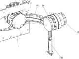
图5为本发明肩第一限位环的结构示意图。Fig. 5 is a schematic structural view of the first limiting ring of the shoulder of the present invention.
其中:1、背板;11、导向杆;12、滚珠丝杠组件;13、肩部调宽电机;2、肩部调节件;21、肩部调节电机;22、肩转动杆;24、肩第一限位环;3、肩部活动件;31、肩部活动电机;32、肩活动杆;4、肘部活动件;41、上臂内外旋电机;42、上臂肘部绳驱管;5、上臂转动机构;51、肘部上半圆环;52、肘部中半圆环;53、肘部下半圆环;6、肘部屈伸件;61、屈伸电机;62、前臂杆;7、腕部旋转件;71、前臂内外旋电机;73、前臂转动机构;74、腕部下半圆环;75、前臂肘部绳驱管;8、腕部左右移动件;81、腕部左右电机;82、第一锥齿轮;83、第二锥齿轮;85、腕部连接杆;9、腕部前后移动件;91、腕部前后电机;92、第三锥齿轮;93、腕部受力板。Among them: 1. Back plate; 11. Guide rod; 12. Ball screw assembly; 13. Shoulder width adjustment motor; 2. Shoulder adjustment part; 21. Shoulder adjustment motor; 22. Shoulder rotation rod; 24.
具体实施方式detailed description
下面结合附图和具体实施方式对本发明进行详细说明。The present invention will be described in detail below in conjunction with the accompanying drawings and specific embodiments.
本发明公开了一种用于力反馈遥操作的穿戴式交互装置,如图1所示,包括背板1、肩部调宽电机13、肩部调节件2,背板1的前侧贴在遥操作使用者的背部,背板1上开设有通过孔,背板1后侧的上半部固定连接有滚珠丝杠组件12,背板1后侧的下半部固定连接有水平设置的导向杆11。The present invention discloses a wearable interactive device for force feedback teleoperation, as shown in Figure 1, comprising a
肩部调宽电机13固定在背板1的后侧,肩部调宽电机13用于带动滚珠丝杠组件12的丝杠转动,进而带动滚珠丝杠组件12的滑块左右移动,肩部调节件2位于背板1的通过孔内,肩部调节件2的上端与滚珠丝杠组件12的滑块固定连接,肩部调节件2的下端与导向滑块固定连接,导向滑块套设在导向杆11上,肩部调节件2用于在滚珠丝杠组件12的滑块的带动下左右移动,进而调整其所处位置并适配佩戴人员的肩宽,导向杆11用于对肩部调节件2进行左右导向。The shoulder
如图2所示,肩部调节件2设置有两个,背板1后侧的下半部、对应两个肩部调节件2的位置还固定连接有左限位传感器和右限位传感器,左限位传感器设置有两个,两个左限位传感器用于测量并发送左侧的肩部调节件2的位置使得左侧的肩部调节件2位于两个左限位传感器之间,右限位传感器设置有两个,两个右限位传感器用于测量并发送右侧的肩部调节件2的位置使得右侧的肩部调节件2位于两个右限位传感器之间。As shown in Figure 2, there are two
如图2和图5所示,肩部调节件2包括:肩部调节电机21、肩转动杆22、肩部第一编码器、肩部第一扭矩传感器、肩第一限位环24,肩部调节电机21位于背板1的后侧,肩部调节电机21与滚珠丝杠组件12的滑块固定连接,肩转动杆22的后端与肩部调节电机21的输出轴固定连接,肩部第一编码器与肩部调节电机21的输出轴连接,肩部第一编码器用于测量和发送肩转动杆22的旋转角度,肩部第一扭矩传感器与肩部调节电机21的输出轴和肩转动杆22连接,肩部第一扭矩传感器用于测量和发送肩转动杆22的扭矩,肩第一限位环24为具有预定开口的环状结构,并与肩部调节电机21的前端固定连接且与肩部调节电机21同轴设置,肩转动杆22通过肩第一限位环24的开口伸出,并在肩部调节电机21的带动下在肩第一限位环24的开口范围内进行旋转。As shown in Fig. 2 and Fig. 5, the shoulder adjusting part 2 comprises: the shoulder adjusting motor 21, the shoulder turning lever 22, the first encoder of the shoulder, the first torque sensor of the shoulder, the first limiting ring 24 of the shoulder, the shoulder The shoulder adjusting motor 21 is located at the rear side of the backboard 1, the shoulder adjusting motor 21 is fixedly connected with the slider of the ball screw assembly 12, the rear end of the shoulder rotating rod 22 is fixedly connected with the output shaft of the shoulder adjusting motor 21, and the shoulder The first encoder is connected with the output shaft of the shoulder adjusting motor 21, the first encoder of the shoulder is used to measure and send the rotation angle of the shoulder turning lever 22, the first torque sensor of the shoulder is connected with the output shaft of the shoulder adjusting motor 21 and the shoulder The rotation rod 22 is connected, the first torque sensor of the shoulder is used to measure and transmit the torque of the shoulder rotation rod 22, the first limit ring 24 of the shoulder is a ring structure with a predetermined opening, and is fixedly connected with the front end of the shoulder adjustment motor 21 And with the shoulder adjusting motor 21 coaxial arrangement, the shoulder rotating rod 22 stretches out by the opening of the first shoulder limiting ring 24, and under the drive of the shoulder adjusting motor 21, within the opening range of the shoulder first limiting ring 24 to rotate.
本发明还包括:两个肩部活动件3,两个肩部活动件3位于肩部调节件2的旁侧,肩部活动件3的上端与肩转动杆22的前端转动连接,肩部活动件3可以其与肩部调节件2的连接点为中心在预定范围内进行旋转。The present invention also includes: two shoulder
各肩部活动件3包括:肩部活动电机31、肩活动杆32、肩部第二编码器、肩部第二扭矩传感器、肩第二限位环34,肩部活动电机31与所述肩转动杆22的前端连接,肩活动杆32的上端与肩部活动电机31的输出轴固定连接,肩部第二编码器与肩部活动电机31的输出轴连接,肩部第二编码器用于测量和发送肩活动杆32的旋转角度,肩部第二扭矩传感器与肩部活动电机31的输出轴和肩活动杆32连接,肩部第二扭矩传感器用于测量和发送肩活动杆32的扭矩,肩第二限位环为具有预定开口的环状结构,并与肩部活动电机31固定连接且与肩部活动电机31同轴设置,肩活动杆32通过肩第二限位环的开口伸出,并在肩部活动电机31的带动下在肩第二限位环的开口范围内进行旋转。Each shoulder
本发明还包括:两个肘部活动件4,两个肘部活动件4位于肩部活动件3的下侧,肘部活动件4的上端与肩活动杆32固定连接,肘部活动件4用于测量上臂的旋内旋外运动。The present invention also includes: two elbow
如图3所示,两个肘部活动件4均包括:上臂内外旋电机41、上臂肘部绳驱管42、上臂内外旋编码器、上臂转动机构5,上臂内外旋电机41固定在肩活动杆32的下端,上臂肘部绳驱管42的上端套设在上臂内外旋电机41的输出轴上,上臂内外旋编码器固定在上臂肘部绳驱管42的下端,上臂内外旋编码器与所述上臂内外旋电机41的输出轴连接,上臂内外旋编码器用于测量并发送上臂肘部绳驱管42的旋转角度,上臂转动机构5位于上臂肘部绳驱管42的旁侧,并通过钢丝绳与上臂肘部绳驱管42绑扎形成传动,上臂转动机构5套设在使用者的肘部上侧,上臂转动机构5用于在上臂内外旋电机41动作时通过上臂肘部绳驱管42带动上臂转动机构5转动,上臂转动机构5还用于通过上臂肘部绳驱管42测量上臂转动机构5的旋转角度。As shown in Figure 3, the two elbow
上臂转动机构5包括:自上而下同轴且水平设置的肘部上半圆环51、肘部中半圆环52、肘部下半圆环53,肘部上半圆环51、肘部中半圆环52、肘部下半圆环53均为半圆形,肘部上半圆环51和肘部下半圆环53的两端均通过肘部固定板固定在一起,并将肘部中半圆环52夹持在肘部上半圆环51和肘部下半圆环53之间,所述肘部中半圆环52可相对于肘部上半圆环51和肘部下半圆环53绕自身轴线在两个肘部固定板之间进行旋转。The upper arm
肘部上半圆环51的下侧、肘部中半圆环52的上侧和下侧、肘部下半圆环53的上侧均开设有肘部凹槽,两个相互配合的肘部凹槽内均放置有多个肘部钢珠,多个肘部钢珠用于在肘部中半圆环52转动时减小摩擦力。The lower side of the
肘部中半圆环52的外壁上开设有多个肘部绳驱槽,各所述肘部绳驱槽用于钢丝绳伸入,钢丝绳的一端固定在肘部中半圆环52的一端,钢丝绳的另一端先顺着肘部绳驱槽绕过肘部中半圆环52外壁的一半、然后绕过上臂肘部绳驱管42外壁一周后再绕过肘部中半圆环52外壁的另一半并固定在肘部中半圆环52的另一端,钢丝绳的绕设方式呈“8”形状。The outer wall of the
本发明还包括:两个肘部屈伸件6,两个肘部屈伸件6均位于肘部活动件4的下侧,肘部屈伸件6的上端与肘部下半圆环53的下侧固定连接,肘部屈伸件6用于带动前臂上下运动或测量前臂上下运动的幅度。The present invention also includes: two elbow flexion and
两个肘部屈伸件6均包括:屈伸电机61、前臂杆62、肘部编码器、肘部扭矩传感器,屈伸电机61固定在肘部下半圆环53的下侧,前臂杆62与屈伸电机61的输出轴固定连接,前臂杆62用于在屈伸电机61的带动下上下运动,肘部编码器与屈伸电机61的输出轴连接,肘部编码器用于测量和发送前臂杆62的旋转角度,肘部扭矩传感器与屈伸电机61的输出轴和前臂杆62连接,肘部扭矩传感器用于测量和发送前臂杆62的扭矩。Both elbow flexion and
本发明还包括:两个腕部旋转件7,两个腕部旋转件7位于肘部屈伸件6的下侧,腕部旋转件7的上端与前臂杆62固定连接。The present invention also includes: two
如图4所示,腕部旋转件7包括:前臂内外旋电机71、前臂肘部绳驱管75、前臂内外旋编码器、前臂转动机构73,前臂内外旋电机71固定在前臂杆62的下端,前臂肘部绳驱管75的上端套设在前臂内外旋电机71的输出轴上,前臂内外旋编码器固定在所述前臂肘部绳驱管75的下端,前臂内外旋编码器与前臂内外旋电机71的输出轴连接,前臂内外旋编码器用于测量和发送前臂肘部绳驱管75的旋转角度,前臂转动机构73位于前臂肘部绳驱管75的旁侧,并通过钢丝绳与前臂肘部绳驱管75绑扎形成传动,前臂转动机构73套设在使用者的腕部上侧,前臂转动机构73用于在前臂内外旋电机71动作时通过前臂肘部绳驱管75带动前臂转动机构73转动,前臂转动机构73还用于通过前臂肘部绳驱管75前臂转动机构测量前臂转动机构73前臂肘部绳驱管的旋转角度。As shown in Figure 4,
前臂转动机构73包括:自上而下同轴且水平设置的腕部上半圆环、腕部中半圆环、腕部下半圆环74,腕部上半圆环、腕部中半圆环、腕部下半圆环74均为半圆形,腕部上半圆环和腕部下半圆环74的两端均通过腕部固定板固定在一起,并将腕部中半圆环夹持在腕部上半圆环和腕部下半圆环74之间,所述腕部中半圆环可相对于腕部上半圆环和腕部下半圆环74绕自身轴线在两个腕部固定板之间进行旋转。The forearm
腕部上半圆环的下侧、腕部中半圆环的上侧和下侧、腕部下半圆环74的上侧均开设有腕部凹槽,两个相互配合的腕部凹槽内放置有多个腕部钢珠,多个腕部钢珠用于在腕部中半圆环转动时减小摩擦力;腕部中半圆环的外壁上开设有多个腕部绳驱槽,钢丝绳的一端固定在腕部中半圆环的一端,其另一端先顺着腕部绳驱槽绕过腕部中半圆环外壁的一半、然后绕过前臂肘部绳驱管75外壁一周后再绕过腕部中半圆环外壁的另一半并固定在腕部中半圆环的另一端,钢丝绳的绕设方式呈“8”形状。The lower side of the upper half ring of the wrist, the upper side and the lower side of the middle half ring of the wrist, and the upper side of the
本发明还包括两个腕部左右移动件8,两个腕部左右移动件8的上端与腕部下半圆环74固定连接,腕部左右移动件8包括:腕部左右电机81、第一锥齿轮82、第二锥齿轮83、腕部连接杆85、腕部移动编码器,腕部左右电机81与腕部下半圆环74固定连接,第一锥齿轮82与腕部左右电机81的输出轴固定连接,第二锥齿轮83与第一锥齿轮82啮合,腕部连接杆85的外端与第二锥齿轮83固定连接,腕部连接杆85的内端用于在腕部外展和内收时以外端为旋转点上下旋转,腕部移动编码器固定腕部连接杆85的外端,腕部移动编码器用于测量和发送腕部连接杆85的旋转角度。The present invention also includes two wrist left and right moving
本发明还包括两个腕部前后移动件9,两个所述腕部前后移动件9的上端与腕部连接杆85的内端连接,两个所述腕部前后移动件9包括:腕部受力板93、第三锥齿轮92、第四锥齿轮、腕部前后电机91、腕部摆动编码器92,腕部受力板93的上端与腕部连接杆85的内端铰接,第三锥齿轮92与所述腕部受力板93的上端固定连接,第四锥齿轮与所述第三锥齿轮92啮合,腕部前后电机91的输出轴与所述第四锥齿轮固定连接,腕部摆动编码器92固定在所述腕部受力板93的上端,腕部摆动编码器92用于测量和发送腕部受力板93的旋转角度。The present invention also includes two wrist front and rear moving
以上仅为本发明的较佳实施例,并不用以限制本发明,凡在本发明的精神和原则之内,所作的任何修改、等同替换、改进等,均应包含在本发明的保护范围之内。The above are only preferred embodiments of the present invention, and are not intended to limit the present invention. Any modifications, equivalent replacements, improvements, etc. made within the spirit and principles of the present invention shall be included in the protection scope of the present invention Inside.
Claims (10)
Priority Applications (1)
| Application Number | Priority Date | Filing Date | Title |
|---|---|---|---|
| CN202211350984.7ACN115609566B (en) | 2022-10-31 | 2022-10-31 | A wearable interactive device for force feedback teleoperation |
Applications Claiming Priority (1)
| Application Number | Priority Date | Filing Date | Title |
|---|---|---|---|
| CN202211350984.7ACN115609566B (en) | 2022-10-31 | 2022-10-31 | A wearable interactive device for force feedback teleoperation |
Publications (2)
| Publication Number | Publication Date |
|---|---|
| CN115609566Atrue CN115609566A (en) | 2023-01-17 |
| CN115609566B CN115609566B (en) | 2024-09-06 |
Family
ID=84876628
Family Applications (1)
| Application Number | Title | Priority Date | Filing Date |
|---|---|---|---|
| CN202211350984.7AActiveCN115609566B (en) | 2022-10-31 | 2022-10-31 | A wearable interactive device for force feedback teleoperation |
Country Status (1)
| Country | Link |
|---|---|
| CN (1) | CN115609566B (en) |
Cited By (3)
| Publication number | Priority date | Publication date | Assignee | Title |
|---|---|---|---|---|
| CN116117777A (en)* | 2023-03-23 | 2023-05-16 | 河南科技大学 | An upper limb and waist power-assisted exoskeleton based on pneumatic artificial muscles |
| CN116872209A (en)* | 2023-07-27 | 2023-10-13 | 浙江理工大学 | Teleoperation method using human upper limb as teleoperation main end controller by combining IMU and rope traction |
| CN118404559A (en)* | 2024-07-01 | 2024-07-30 | 浙江大学 | Man-machine safety interaction-oriented wearable teleoperation intelligent equipment |
Citations (5)
| Publication number | Priority date | Publication date | Assignee | Title |
|---|---|---|---|---|
| CN1488474A (en)* | 2003-09-09 | 2004-04-14 | 北京航空航天大学 | An exoskeleton wearable data arm with force feedback for human-computer interaction |
| US20070225620A1 (en)* | 2006-03-23 | 2007-09-27 | Carignan Craig R | Portable Arm Exoskeleton for Shoulder Rehabilitation |
| KR101446215B1 (en)* | 2013-06-27 | 2014-10-02 | 한성대학교 산학협력단 | Exoskeletal robot arm |
| CN104385266A (en)* | 2014-08-28 | 2015-03-04 | 北京邮电大学 | Seven-degree-of-freedom external skeleton type teleoperation main hand |
| CN114986478A (en)* | 2021-03-01 | 2022-09-02 | 腾讯科技(深圳)有限公司 | Arm exoskeleton, upper body exoskeleton and teleoperation system |
- 2022
- 2022-10-31CNCN202211350984.7Apatent/CN115609566B/enactiveActive
Patent Citations (5)
| Publication number | Priority date | Publication date | Assignee | Title |
|---|---|---|---|---|
| CN1488474A (en)* | 2003-09-09 | 2004-04-14 | 北京航空航天大学 | An exoskeleton wearable data arm with force feedback for human-computer interaction |
| US20070225620A1 (en)* | 2006-03-23 | 2007-09-27 | Carignan Craig R | Portable Arm Exoskeleton for Shoulder Rehabilitation |
| KR101446215B1 (en)* | 2013-06-27 | 2014-10-02 | 한성대학교 산학협력단 | Exoskeletal robot arm |
| CN104385266A (en)* | 2014-08-28 | 2015-03-04 | 北京邮电大学 | Seven-degree-of-freedom external skeleton type teleoperation main hand |
| CN114986478A (en)* | 2021-03-01 | 2022-09-02 | 腾讯科技(深圳)有限公司 | Arm exoskeleton, upper body exoskeleton and teleoperation system |
Non-Patent Citations (1)
| Title |
|---|
| 李世远;李双鲲;高翔;蔡杰;: "基于力反馈的上肢康复机器人", 齐齐哈尔大学学报(自然科学版), no. 01, 15 January 2015 (2015-01-15), pages 31 - 34* |
Cited By (3)
| Publication number | Priority date | Publication date | Assignee | Title |
|---|---|---|---|---|
| CN116117777A (en)* | 2023-03-23 | 2023-05-16 | 河南科技大学 | An upper limb and waist power-assisted exoskeleton based on pneumatic artificial muscles |
| CN116872209A (en)* | 2023-07-27 | 2023-10-13 | 浙江理工大学 | Teleoperation method using human upper limb as teleoperation main end controller by combining IMU and rope traction |
| CN118404559A (en)* | 2024-07-01 | 2024-07-30 | 浙江大学 | Man-machine safety interaction-oriented wearable teleoperation intelligent equipment |
Also Published As
| Publication number | Publication date |
|---|---|
| CN115609566B (en) | 2024-09-06 |
Similar Documents
| Publication | Publication Date | Title |
|---|---|---|
| CN115609566A (en) | A wearable interactive device for force feedback teleoperation | |
| CN112476478B (en) | A bionic rope-driven four-degree-of-freedom arm for human-robot collaboration | |
| CN104589310B (en) | A kind of self adaptation multiple degrees of freedom Apery manipulator based on Pneumatic artificial muscle | |
| CN104382674B (en) | A kind of drive lacking prosthetic hand reappearing staff crawl function | |
| CN104942791B (en) | Rope pulled and pneumatic muscle driven multi-degree-of-freedom bionic manipulator | |
| CN102152299B (en) | (6 plus 1)-dimension force feedback sensing device | |
| CN104385266A (en) | Seven-degree-of-freedom external skeleton type teleoperation main hand | |
| CN116852336A (en) | Upper body teleoperation force feedback equipment for double-arm robot | |
| CN103128744A (en) | Humanoid flexible mechanical arm device | |
| CN107553467B (en) | Multifunctional master hand device with low gravity center | |
| CN212794946U (en) | Upper limb exoskeleton robot with collinear human-computer shoulder rotation center lines | |
| CN101817181A (en) | Six-degree-of-freedom flexible mechanical arm based on pneumatic muscles | |
| CN118322248B (en) | Three-degree-of-freedom robot joint and manipulator | |
| CN114770478B (en) | Remote variable-rigidity reconfigurable modularized exoskeleton and control system and control method thereof | |
| CN107397648A (en) | A kind of hand convalescence device and system | |
| CN104972452A (en) | Outer skeleton type arm joint information detection device | |
| CN115871006A (en) | A wearable rigid-flexible coupled force feedback dexterous hand skeleton | |
| CN206019701U (en) | A kind of wearable device test device | |
| CN116619336A (en) | Force feedback exoskeleton mechanical arm based on active and passive joints | |
| CN209092062U (en) | Eight-degree-of-freedom local force feedback bionic upper limb exoskeleton master hand | |
| CN111805517B (en) | An upper limb exoskeleton robot with co-linear human-machine shoulder rotation center lines | |
| CN110664583A (en) | An eight-degree-of-freedom local force feedback bionic upper limb exoskeleton master hand | |
| CN113084800B (en) | A wearable full-joint follow-up remote control device | |
| CN119704164A (en) | Humanoid mechanical arm | |
| CN204414097U (en) | A kind of self adaptation multiple degrees of freedom Apery manipulator based on Pneumatic artificial muscle |
Legal Events
| Date | Code | Title | Description |
|---|---|---|---|
| PB01 | Publication | ||
| PB01 | Publication | ||
| SE01 | Entry into force of request for substantive examination | ||
| SE01 | Entry into force of request for substantive examination | ||
| GR01 | Patent grant | ||
| GR01 | Patent grant |