CN115607249A - Intelligent orthopedic implant, its monitoring system, and state judgment method - Google Patents
Intelligent orthopedic implant, its monitoring system, and state judgment methodDownload PDFInfo
- Publication number
- CN115607249A CN115607249ACN202110504754.0ACN202110504754ACN115607249ACN 115607249 ACN115607249 ACN 115607249ACN 202110504754 ACN202110504754 ACN 202110504754ACN 115607249 ACN115607249 ACN 115607249A
- Authority
- CN
- China
- Prior art keywords
- implant
- voltage
- pressure
- sensitive layer
- resistance
- Prior art date
- Legal status (The legal status is an assumption and is not a legal conclusion. Google has not performed a legal analysis and makes no representation as to the accuracy of the status listed.)
- Pending
Links
Images


Classifications
- A—HUMAN NECESSITIES
- A61—MEDICAL OR VETERINARY SCIENCE; HYGIENE
- A61B—DIAGNOSIS; SURGERY; IDENTIFICATION
- A61B17/00—Surgical instruments, devices or methods
- A61B17/56—Surgical instruments or methods for treatment of bones or joints; Devices specially adapted therefor
- A61B17/58—Surgical instruments or methods for treatment of bones or joints; Devices specially adapted therefor for osteosynthesis, e.g. bone plates, screws or setting implements
- A61B17/68—Internal fixation devices, including fasteners and spinal fixators, even if a part thereof projects from the skin
- A61B17/84—Fasteners therefor or fasteners being internal fixation devices
- A61B17/86—Pins or screws or threaded wires; nuts therefor
- A—HUMAN NECESSITIES
- A61—MEDICAL OR VETERINARY SCIENCE; HYGIENE
- A61B—DIAGNOSIS; SURGERY; IDENTIFICATION
- A61B17/00—Surgical instruments, devices or methods
- A61B17/56—Surgical instruments or methods for treatment of bones or joints; Devices specially adapted therefor
- A—HUMAN NECESSITIES
- A61—MEDICAL OR VETERINARY SCIENCE; HYGIENE
- A61B—DIAGNOSIS; SURGERY; IDENTIFICATION
- A61B17/00—Surgical instruments, devices or methods
- A61B17/56—Surgical instruments or methods for treatment of bones or joints; Devices specially adapted therefor
- A61B17/58—Surgical instruments or methods for treatment of bones or joints; Devices specially adapted therefor for osteosynthesis, e.g. bone plates, screws or setting implements
- A61B17/68—Internal fixation devices, including fasteners and spinal fixators, even if a part thereof projects from the skin
- A61B17/70—Spinal positioners or stabilisers, e.g. stabilisers comprising fluid filler in an implant
- A—HUMAN NECESSITIES
- A61—MEDICAL OR VETERINARY SCIENCE; HYGIENE
- A61B—DIAGNOSIS; SURGERY; IDENTIFICATION
- A61B17/00—Surgical instruments, devices or methods
- A61B17/56—Surgical instruments or methods for treatment of bones or joints; Devices specially adapted therefor
- A61B17/58—Surgical instruments or methods for treatment of bones or joints; Devices specially adapted therefor for osteosynthesis, e.g. bone plates, screws or setting implements
- A61B17/68—Internal fixation devices, including fasteners and spinal fixators, even if a part thereof projects from the skin
- A61B17/72—Intramedullary devices, e.g. pins or nails
- A—HUMAN NECESSITIES
- A61—MEDICAL OR VETERINARY SCIENCE; HYGIENE
- A61B—DIAGNOSIS; SURGERY; IDENTIFICATION
- A61B17/00—Surgical instruments, devices or methods
- A61B17/56—Surgical instruments or methods for treatment of bones or joints; Devices specially adapted therefor
- A61B17/58—Surgical instruments or methods for treatment of bones or joints; Devices specially adapted therefor for osteosynthesis, e.g. bone plates, screws or setting implements
- A61B17/68—Internal fixation devices, including fasteners and spinal fixators, even if a part thereof projects from the skin
- A61B17/80—Cortical plates, i.e. bone plates; Instruments for holding or positioning cortical plates, or for compressing bones attached to cortical plates
- A—HUMAN NECESSITIES
- A61—MEDICAL OR VETERINARY SCIENCE; HYGIENE
- A61B—DIAGNOSIS; SURGERY; IDENTIFICATION
- A61B17/00—Surgical instruments, devices or methods
- A61B17/56—Surgical instruments or methods for treatment of bones or joints; Devices specially adapted therefor
- A61B17/58—Surgical instruments or methods for treatment of bones or joints; Devices specially adapted therefor for osteosynthesis, e.g. bone plates, screws or setting implements
- A61B17/68—Internal fixation devices, including fasteners and spinal fixators, even if a part thereof projects from the skin
- A61B17/84—Fasteners therefor or fasteners being internal fixation devices
- A—HUMAN NECESSITIES
- A61—MEDICAL OR VETERINARY SCIENCE; HYGIENE
- A61F—FILTERS IMPLANTABLE INTO BLOOD VESSELS; PROSTHESES; DEVICES PROVIDING PATENCY TO, OR PREVENTING COLLAPSING OF, TUBULAR STRUCTURES OF THE BODY, e.g. STENTS; ORTHOPAEDIC, NURSING OR CONTRACEPTIVE DEVICES; FOMENTATION; TREATMENT OR PROTECTION OF EYES OR EARS; BANDAGES, DRESSINGS OR ABSORBENT PADS; FIRST-AID KITS
- A61F2/00—Filters implantable into blood vessels; Prostheses, i.e. artificial substitutes or replacements for parts of the body; Appliances for connecting them with the body; Devices providing patency to, or preventing collapsing of, tubular structures of the body, e.g. stents
- A61F2/02—Prostheses implantable into the body
- A61F2/30—Joints
- A61F2/32—Joints for the hip
- A—HUMAN NECESSITIES
- A61—MEDICAL OR VETERINARY SCIENCE; HYGIENE
- A61F—FILTERS IMPLANTABLE INTO BLOOD VESSELS; PROSTHESES; DEVICES PROVIDING PATENCY TO, OR PREVENTING COLLAPSING OF, TUBULAR STRUCTURES OF THE BODY, e.g. STENTS; ORTHOPAEDIC, NURSING OR CONTRACEPTIVE DEVICES; FOMENTATION; TREATMENT OR PROTECTION OF EYES OR EARS; BANDAGES, DRESSINGS OR ABSORBENT PADS; FIRST-AID KITS
- A61F2/00—Filters implantable into blood vessels; Prostheses, i.e. artificial substitutes or replacements for parts of the body; Appliances for connecting them with the body; Devices providing patency to, or preventing collapsing of, tubular structures of the body, e.g. stents
- A61F2/02—Prostheses implantable into the body
- A61F2/30—Joints
- A61F2/38—Joints for elbows or knees
- A—HUMAN NECESSITIES
- A61—MEDICAL OR VETERINARY SCIENCE; HYGIENE
- A61F—FILTERS IMPLANTABLE INTO BLOOD VESSELS; PROSTHESES; DEVICES PROVIDING PATENCY TO, OR PREVENTING COLLAPSING OF, TUBULAR STRUCTURES OF THE BODY, e.g. STENTS; ORTHOPAEDIC, NURSING OR CONTRACEPTIVE DEVICES; FOMENTATION; TREATMENT OR PROTECTION OF EYES OR EARS; BANDAGES, DRESSINGS OR ABSORBENT PADS; FIRST-AID KITS
- A61F2/00—Filters implantable into blood vessels; Prostheses, i.e. artificial substitutes or replacements for parts of the body; Appliances for connecting them with the body; Devices providing patency to, or preventing collapsing of, tubular structures of the body, e.g. stents
- A61F2/02—Prostheses implantable into the body
- A61F2/30—Joints
- A61F2/40—Joints for shoulders
- A—HUMAN NECESSITIES
- A61—MEDICAL OR VETERINARY SCIENCE; HYGIENE
- A61F—FILTERS IMPLANTABLE INTO BLOOD VESSELS; PROSTHESES; DEVICES PROVIDING PATENCY TO, OR PREVENTING COLLAPSING OF, TUBULAR STRUCTURES OF THE BODY, e.g. STENTS; ORTHOPAEDIC, NURSING OR CONTRACEPTIVE DEVICES; FOMENTATION; TREATMENT OR PROTECTION OF EYES OR EARS; BANDAGES, DRESSINGS OR ABSORBENT PADS; FIRST-AID KITS
- A61F2/00—Filters implantable into blood vessels; Prostheses, i.e. artificial substitutes or replacements for parts of the body; Appliances for connecting them with the body; Devices providing patency to, or preventing collapsing of, tubular structures of the body, e.g. stents
- A61F2/02—Prostheses implantable into the body
- A61F2/30—Joints
- A61F2/44—Joints for the spine, e.g. vertebrae, spinal discs
- A—HUMAN NECESSITIES
- A61—MEDICAL OR VETERINARY SCIENCE; HYGIENE
- A61F—FILTERS IMPLANTABLE INTO BLOOD VESSELS; PROSTHESES; DEVICES PROVIDING PATENCY TO, OR PREVENTING COLLAPSING OF, TUBULAR STRUCTURES OF THE BODY, e.g. STENTS; ORTHOPAEDIC, NURSING OR CONTRACEPTIVE DEVICES; FOMENTATION; TREATMENT OR PROTECTION OF EYES OR EARS; BANDAGES, DRESSINGS OR ABSORBENT PADS; FIRST-AID KITS
- A61F2/00—Filters implantable into blood vessels; Prostheses, i.e. artificial substitutes or replacements for parts of the body; Appliances for connecting them with the body; Devices providing patency to, or preventing collapsing of, tubular structures of the body, e.g. stents
- A61F2/02—Prostheses implantable into the body
- A61F2/30—Joints
- A61F2/46—Special tools for implanting artificial joints
- A61F2/4657—Measuring instruments used for implanting artificial joints
- A—HUMAN NECESSITIES
- A61—MEDICAL OR VETERINARY SCIENCE; HYGIENE
- A61B—DIAGNOSIS; SURGERY; IDENTIFICATION
- A61B2562/00—Details of sensors; Constructional details of sensor housings or probes; Accessories for sensors
- A61B2562/02—Details of sensors specially adapted for in-vivo measurements
- A—HUMAN NECESSITIES
- A61—MEDICAL OR VETERINARY SCIENCE; HYGIENE
- A61B—DIAGNOSIS; SURGERY; IDENTIFICATION
- A61B2562/00—Details of sensors; Constructional details of sensor housings or probes; Accessories for sensors
- A61B2562/02—Details of sensors specially adapted for in-vivo measurements
- A61B2562/0247—Pressure sensors
- A—HUMAN NECESSITIES
- A61—MEDICAL OR VETERINARY SCIENCE; HYGIENE
- A61B—DIAGNOSIS; SURGERY; IDENTIFICATION
- A61B2562/00—Details of sensors; Constructional details of sensor housings or probes; Accessories for sensors
- A61B2562/02—Details of sensors specially adapted for in-vivo measurements
- A61B2562/0261—Strain gauges
- A—HUMAN NECESSITIES
- A61—MEDICAL OR VETERINARY SCIENCE; HYGIENE
- A61F—FILTERS IMPLANTABLE INTO BLOOD VESSELS; PROSTHESES; DEVICES PROVIDING PATENCY TO, OR PREVENTING COLLAPSING OF, TUBULAR STRUCTURES OF THE BODY, e.g. STENTS; ORTHOPAEDIC, NURSING OR CONTRACEPTIVE DEVICES; FOMENTATION; TREATMENT OR PROTECTION OF EYES OR EARS; BANDAGES, DRESSINGS OR ABSORBENT PADS; FIRST-AID KITS
- A61F2/00—Filters implantable into blood vessels; Prostheses, i.e. artificial substitutes or replacements for parts of the body; Appliances for connecting them with the body; Devices providing patency to, or preventing collapsing of, tubular structures of the body, e.g. stents
- A61F2/02—Prostheses implantable into the body
- A61F2/30—Joints
- A61F2/46—Special tools for implanting artificial joints
- A61F2/4657—Measuring instruments used for implanting artificial joints
- A61F2002/4658—Measuring instruments used for implanting artificial joints for measuring dimensions, e.g. length
- A—HUMAN NECESSITIES
- A61—MEDICAL OR VETERINARY SCIENCE; HYGIENE
- A61F—FILTERS IMPLANTABLE INTO BLOOD VESSELS; PROSTHESES; DEVICES PROVIDING PATENCY TO, OR PREVENTING COLLAPSING OF, TUBULAR STRUCTURES OF THE BODY, e.g. STENTS; ORTHOPAEDIC, NURSING OR CONTRACEPTIVE DEVICES; FOMENTATION; TREATMENT OR PROTECTION OF EYES OR EARS; BANDAGES, DRESSINGS OR ABSORBENT PADS; FIRST-AID KITS
- A61F2/00—Filters implantable into blood vessels; Prostheses, i.e. artificial substitutes or replacements for parts of the body; Appliances for connecting them with the body; Devices providing patency to, or preventing collapsing of, tubular structures of the body, e.g. stents
- A61F2/02—Prostheses implantable into the body
- A61F2/30—Joints
- A61F2/46—Special tools for implanting artificial joints
- A61F2/4657—Measuring instruments used for implanting artificial joints
- A61F2002/4666—Measuring instruments used for implanting artificial joints for measuring force, pressure or mechanical tension
Landscapes
- Health & Medical Sciences (AREA)
- Orthopedic Medicine & Surgery (AREA)
- Life Sciences & Earth Sciences (AREA)
- Surgery (AREA)
- Engineering & Computer Science (AREA)
- Biomedical Technology (AREA)
- Animal Behavior & Ethology (AREA)
- Public Health (AREA)
- Veterinary Medicine (AREA)
- Heart & Thoracic Surgery (AREA)
- General Health & Medical Sciences (AREA)
- Nuclear Medicine, Radiotherapy & Molecular Imaging (AREA)
- Transplantation (AREA)
- Neurology (AREA)
- Molecular Biology (AREA)
- Cardiology (AREA)
- Oral & Maxillofacial Surgery (AREA)
- Medical Informatics (AREA)
- Vascular Medicine (AREA)
- Physical Education & Sports Medicine (AREA)
- Biophysics (AREA)
- Prostheses (AREA)
Abstract
Description
Translated fromChinese技术领域technical field
本发明涉及骨科植入物领域,具体涉及一种智能骨科植入物及其监测系统、状态判断方法。The invention relates to the field of orthopedic implants, in particular to an intelligent orthopedic implant, a monitoring system and a state judgment method thereof.
背景技术Background technique
骨科植入物产品,主要包括脊柱类产品,创伤类产品,人工关节类产品、神经外科产品(颅骨修复钛网、颅骨接骨板)、胸外科骨科用产品(如胸骨内固定植入物、肋骨内固定植入物产品等)等。常见的骨科植入物有椎间融合器、骨科接骨板、骨科钉棒固定系统(如脊柱后路椎弓根螺钉固定系统、脊柱前路钉棒固定系统等多种类别)、骨科钉-板系统、髋关节假体、膝关节假体、人工椎体、髓内钉、肘关节假体、腕关节假体、肩关节假体、踝关节假体、螺钉、钛网、骨科固定针、骨科固定线缆、骨科固定铆定植入物、骨科外固定支架植入物(固定支架的钉和针为植入物,连接棒为2类医疗器械)、骨科个性化定制植入物、骨科肿瘤植入物产品、骨科植入物垫片等。骨科植入物种类包含但不限于上述产品种类和范畴;Orthopedic implant products mainly include spine products, trauma products, artificial joint products, neurosurgery products (titanium mesh for skull repair, skull plate), orthopedic products for thoracic surgery (such as sternal internal fixation implants, rib Internal fixation implant products, etc.), etc. Common orthopedic implants include intervertebral fusion cages, orthopedic bone plates, orthopedic screw-rod fixation systems (such as posterior spinal pedicle screw fixation systems, anterior spinal screw-rod fixation systems, etc.), orthopedic screw-plate System, hip prosthesis, knee prosthesis, artificial vertebral body, intramedullary nail, elbow prosthesis, wrist prosthesis, shoulder prosthesis, ankle prosthesis, screws, titanium mesh, orthopedic fixation pins, orthopedics Fixation cables, orthopedic fixed riveting implants, orthopedic external fixation implants (nails and needles for fixing brackets are implants, and connecting rods are
例如骨科螺钉,临床中常用于固定骨科植入物以及内部骨折或脱位的固定,单独或与接骨板、钉棒系统等组合使用,通过直接拧入两个不同骨块或固定骨板等植入物实现骨折的固定,定位骨骼并促进骨愈合,常用的有松质骨螺钉、皮质骨螺钉、骨栓和空心螺钉、髓内钉、椎弓根螺钉等等。For example, orthopedic screws are commonly used in clinical practice to fix orthopedic implants and fix internal fractures or dislocations. They are used alone or in combination with bone plate, screw-rod system, etc., and are implanted by directly screwing into two different bone blocks or fixing bone plates. The material realizes the fixation of the fracture, locates the bone and promotes bone healing. Commonly used are cancellous bone screw, cortical bone screw, bone plug and cannulated screw, intramedullary nail, pedicle screw and so on.
骨科植入物植入人体以后,随着患者骨愈合过程或患者康复过程中,骨科植入物(例如螺钉)可能会出现弯曲变形、应力集中、松动、退出、移位、断裂等失效情况,造成例如接骨板断裂、螺钉断裂松动等手术失败,严重者常需要二次翻修手术。现有的骨科植入物不能自我监测植入物失效,也不能对植入物失效进行预警,是当前骨科植入物的一大显著不足;After the orthopedic implant is implanted in the human body, along with the patient's bone healing process or the patient's rehabilitation process, the orthopedic implant (such as a screw) may experience failures such as bending deformation, stress concentration, loosening, withdrawal, displacement, and fracture. Such as bone plate breakage, screw breakage and loosening and other surgical failures, severe cases often require secondary revision surgery. Existing orthopedic implants cannot self-monitor implant failure, nor can they provide early warning of implant failure, which is a significant deficiency of current orthopedic implants;
植入物失效可能是由于微动、应力集中等长时间作用的一个累积过程,如松动、变形、移位、退钉、断裂等,植入物失效也可能是一个瞬时作用力超过了植入物的负荷,瞬时形成松动、变形、移位、退钉、断裂等。Implant failure may be due to a long-term cumulative process of fretting, stress concentration, etc., such as loosening, deformation, displacement, screw withdrawal, fracture, etc. Implant failure may also be due to an instantaneous force exceeding the implantation force. The load of the object will cause loosening, deformation, displacement, back nailing, fracture, etc. in an instant.
在现有的技术条件和医疗模式下,骨科患者术后,在3月、6月或规定的时间节点到医院进行随访,医生对患者进行体格检查以及患者进行X光、CT等辅助检查,在回归医院的随访过程中,医生可以通过物理检测或辅助检查可以发现植入物失效与否。Under the existing technical conditions and medical model, orthopedic patients will go to the hospital for follow-up visits in March, June or at the specified time point after surgery. Doctors will perform physical examinations on patients and auxiliary examinations such as X-ray and CT. During the follow-up process of returning to the hospital, the doctor can find out whether the implant has failed or not through physical inspection or auxiliary inspection.
但现有技术存在如下不足:But existing technology has following deficiency:
1、不能实时的连续的对植入物进行监测,存在遗漏风险;1. Implants cannot be monitored continuously in real time, and there is a risk of omission;
2、不能对植入物失效进行预警和早期干预,在累积过程中,早期发现、早期预警,则可能避免植入物失效的严重和恶化,从而避免患者手术失败或二次手术;2. It is impossible to carry out early warning and early intervention for implant failure. In the accumulation process, early detection and early warning may avoid the seriousness and deterioration of implant failure, thereby avoiding surgical failure or secondary surgery for patients;
3、不能精准的对植入物失效状态进行判定,通过物理体格检查、X光和CT检查对植入物状态进行判定比较滞后,并且是间接的检测,误判风险较高,对松动、变形、移位等失效的早期阶段误判率更高,也严重依赖于临床医生和放射科诊断医生的经验判断;3. It is not possible to accurately determine the failure status of the implant. It is relatively lagging to determine the status of the implant through physical examination, X-ray and CT examination, and it is an indirect detection, which has a high risk of misjudgment. The misjudgment rate is higher in the early stages of failures such as displacement and displacement, and it also relies heavily on the experience and judgment of clinicians and radiologists;
4、现有的技术手段存在辐射危害;4. Existing technical means have radiation hazards;
5、现有的技术手段不能自我监测,不能远程监测;患者往返医院多次检查,存在误工、交通、检查费等多种费用,不利于降低医疗负担;5. Existing technical means cannot self-monitor or remotely monitor; patients go to and from the hospital for multiple inspections, and there are various expenses such as work delays, transportation, inspection fees, etc., which is not conducive to reducing medical burden;
6、不能对植入物的活动度进行实时监测分析。6. It is impossible to monitor and analyze the activity of the implant in real time.
现有的螺钉或者螺栓,如CN109632006A公开的“一种无线智能螺栓及在线监测系统”,螺栓主体中心设有一定深度和直径的中心孔,中心孔底部加工有安装螺纹,测力杆件的一端通过螺纹连接固定于螺栓主体中心孔的底部,另一端与螺栓主体头部内置孔底面紧密接触,测力杆件上均匀布置有多个应变片,测力杆件的变形与螺栓主体变形成正比。Existing screws or bolts, such as "a wireless intelligent bolt and online monitoring system" disclosed in CN109632006A, the center of the bolt body is provided with a central hole with a certain depth and diameter, the bottom of the central hole is processed with mounting threads, and one end of the force-measuring rod is It is fixed at the bottom of the center hole of the bolt body through threaded connection, and the other end is in close contact with the bottom surface of the built-in hole in the head of the bolt body. Multiple strain gauges are evenly arranged on the force-measuring rod, and the deformation of the force-measuring rod is proportional to the deformation of the bolt body. .
上述技术方案虽然实现了对螺钉监控并确定螺栓主体的变形,但其原理是通过测力杆件的变形与螺栓主体变形成正比来反应螺杆的形变,再通过测力杆件上的应变片来反应测力杆件的形变,此种测量变形的方式只能粗略测出形变;并且其主要使用于建筑、桥梁、机械设备等领域,不能用于医学领域。Although the above technical solution realizes the monitoring of the screw and determines the deformation of the bolt body, its principle is to reflect the deformation of the screw rod through the deformation of the force-measuring rod in direct proportion to the deformation of the bolt body, and then through the strain gauge on the force-measuring rod. Response to the deformation of the force-measuring rod, this method of measuring deformation can only roughly measure the deformation; and it is mainly used in the fields of construction, bridges, mechanical equipment, etc., and cannot be used in the medical field.
因此,当前骨科植入物尚需一种能够实现自我实时远程智能监测的、能够对植入物失效状态进行精确判断,并且根据相应状态进行预警的智能骨科植入物设计。Therefore, the current orthopedic implants still need an intelligent orthopedic implant design that can realize self-real-time remote intelligent monitoring, accurately judge the failure state of the implant, and provide early warning according to the corresponding state.
发明内容Contents of the invention
本发明的目的是提供一种智能骨科植入物及其监测系统、状态判断方法,实现了对骨科植入物状态的精确判断,并根据骨科植入物状态进行相应预警提示,极大地提高了骨科植入物的使用安全性。The purpose of the present invention is to provide an intelligent orthopedic implant and its monitoring system and state judgment method, which realizes the accurate judgment of the state of the orthopedic implant, and provides corresponding early warning prompts according to the state of the orthopedic implant, which greatly improves the Safety of Orthopedic Implants.
本发明采取如下技术方案实现上述目的,智能骨科植入物,包括植入物本体,所述植入物本体上设置有压敏层,所述压敏层上分布有多个测量点,任意两个相邻测量点之间的电压或电阻随着植入物本体的形变而发生相应变化。The present invention adopts the following technical solutions to achieve the above object. The intelligent orthopedic implant includes an implant body, the implant body is provided with a pressure-sensitive layer, and a plurality of measuring points are distributed on the pressure-sensitive layer. Any two The voltage or resistance between two adjacent measurement points changes accordingly with the deformation of the implant body.
进一步的是,所述植入物本体内部设置有恒流源、电压测量模块以及通信模块,所述恒流源用于为压敏层提供电流,所述电压测量模块用于实时测量任意两个相邻测量点之间的电压数据,并将电压数据通过通信模块发送给外部终端。Further, the implant body is provided with a constant current source, a voltage measurement module, and a communication module, the constant current source is used to provide current for the pressure-sensitive layer, and the voltage measurement module is used to measure any two phases in real time. The voltage data between adjacent measurement points, and the voltage data is sent to the external terminal through the communication module.
进一步的是,所述植入物本体内部设置有模拟开关、电桥以及通信模块,测量点由引线接入模拟开关的输入端,模拟开关的输出端接入电桥,所述电桥用来测量两相邻测量点之间的电阻数据,并将电阻数据通过通信模块发送给外部终端。Further, the implant body is provided with an analog switch, an electric bridge and a communication module, the measurement point is connected to the input end of the analog switch by a lead wire, and the output end of the analog switch is connected to the electric bridge, and the electric bridge is used for Measure the resistance data between two adjacent measurement points, and send the resistance data to the external terminal through the communication module.
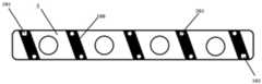
进一步的是,所述植入物为螺钉,所述螺钉螺纹之间的沟槽表面设置有压敏层,所述压敏层紧贴在螺纹之间的沟槽表面。Further, the implant is a screw, and the surface of the groove between the screw threads is provided with a pressure-sensitive layer, and the pressure-sensitive layer is closely attached to the surface of the groove between the threads.
进一步的是,所述植入物为膝关节假体,所述膝关节假体的垫片表面设置有压敏层,所述压敏层设置在膝关节假体的垫片与膝关节假体中的股骨髁组件接触的位置。Further, the implant is a knee joint prosthesis, a pressure-sensitive layer is provided on the surface of the gasket of the knee joint prosthesis, and the pressure-sensitive layer is arranged between the gasket of the knee joint prosthesis and the knee joint prosthesis. The location where the components of the femoral condyle contact.
进一步的是,所述植入物为踝关节假体,所述踝关节假体的垫片表面设置有压敏层。Further, the implant is an ankle joint prosthesis, and a pressure-sensitive layer is provided on the gasket surface of the ankle joint prosthesis.
进一步的是,所述植入物为接骨板,所述接骨板螺孔之间的表面设置有压敏层。Further, the implant is a bone plate, and the surface between the screw holes of the bone plate is provided with a pressure-sensitive layer.
进一步的是,所述植入物为髋关节假体,所述髋关节假体的球体表面设置有压敏层,所述压敏层设置在髋关节假体的球体与髋关节假体内衬接触的表面。Further, the implant is a hip joint prosthesis, a pressure-sensitive layer is provided on the surface of the spherical body of the hip joint prosthesis, and the pressure-sensitive layer is arranged between the spherical body of the hip joint prosthesis and the inner lining of the hip joint prosthesis. contact surface.
进一步的是,所述植入物为肩关节假体,所述肩关节假体的球体表面设置有压敏层,所述压敏层设置在肩关节假体的球体与肩关节假体内衬接触的表面。Further, the implant is a shoulder joint prosthesis, the surface of the spherical body of the shoulder joint prosthesis is provided with a pressure-sensitive layer, and the pressure-sensitive layer is arranged between the spherical body of the shoulder joint prosthesis and the lining of the shoulder joint prosthesis. contact surface.
进一步的是,所述植入物为腕关节假体,所述腕关节假体的球体表面设置有压敏层,所述压敏层设置在腕关节假体的球体与腕关节假体内衬接触的表面。Further, the implant is a wrist prosthesis, the surface of the sphere of the wrist prosthesis is provided with a pressure-sensitive layer, and the pressure-sensitive layer is arranged between the sphere of the wrist prosthesis and the inner lining of the wrist joint prosthesis. contact surface.
进一步的是,所述植入物为髓内棒,所述髓内棒螺孔之间的表面设置有压敏层。Further, the implant is an intramedullary rod, and the surface between the screw holes of the intramedullary rod is provided with a pressure-sensitive layer.
进一步的是,所述植入物为钉棒系统,钉棒系统包括弓根钉以及棒,所述弓根钉螺纹之间的凹槽中设置有压敏层,所述棒螺孔之间的表面设置有压敏层。Further, the implant is a screw-and-rod system, and the screw-and-rod system includes pedicle screws and rods, a pressure-sensitive layer is arranged in the grooves between the screw threads of the pedicle screws, and a pressure-sensitive layer is arranged in the grooves between the screw holes of the rods. The surface is provided with a pressure-sensitive layer.
进一步的是,所述植入物为骨科固定支架,所述骨科固定支架包括固定钢针以及固定连杆,所述固定钢针表面设置有压敏层,所述固定连杆表面设置有压敏层。Further, the implant is an orthopedic fixation bracket, and the orthopedic fixation bracket includes a fixed steel needle and a fixed connecting rod, the surface of the fixed steel needle is provided with a pressure-sensitive layer, and the surface of the fixed connecting rod is provided with a pressure-sensitive layer.
进一步的是,所述植入物为人工椎体,所述人工椎体表面设置有压敏层。Further, the implant is an artificial vertebral body, and the surface of the artificial vertebral body is provided with a pressure-sensitive layer.
进一步的是,所述植入物为椎间融合器,所述椎间融合器表面设置有压敏层。Further, the implant is an intervertebral fusion device, and the surface of the intervertebral fusion device is provided with a pressure-sensitive layer.
进一步的是,所述压敏层为压敏薄膜带,所述压敏薄膜带两端设置有电流注入点。Further, the pressure-sensitive layer is a pressure-sensitive film tape, and current injection points are arranged at both ends of the pressure-sensitive film tape.
进一步的是,所述压敏薄膜带包括保护层以及内置于保护层之间的压敏感应层。Further, the pressure-sensitive film tape includes protective layers and a pressure-sensitive layer built between the protective layers.
智能骨科植入物监测系统,包括智能终端以及上述所述的智能骨科植入物,所述智能终端用于根据电压或电阻数据对植入物的受力情况进行分析,判断出植入物当前的状态并根据植入物状态进行相应预警提示。The intelligent orthopedic implant monitoring system includes an intelligent terminal and the above-mentioned intelligent orthopedic implant, and the intelligent terminal is used to analyze the force of the implant according to the voltage or resistance data, and determine the current state of the implant. The state of the implant and the corresponding warning prompt according to the state of the implant.
智能骨科植入物状态判断方法,应用于上述所述的智能骨科植入物监测系统,包括:The method for judging the state of an intelligent orthopedic implant is applied to the above-mentioned intelligent orthopedic implant monitoring system, including:
实时监测各相邻测量点之间的电压或电阻,若任意相邻测量点之间的电压或电阻不等于各相邻测量点对应的初始电压或电阻,则判定植入物出现了松动或弯曲或断裂。Monitor the voltage or resistance between adjacent measurement points in real time. If the voltage or resistance between any adjacent measurement points is not equal to the initial voltage or resistance corresponding to each adjacent measurement point, it is determined that the implant has loosened or bent or break.
进一步的是,判定植入物出现松动的具体方法包括:Furthermore, the specific methods for determining the loosening of the implant include:
实时监测各相邻测量点之间的电压或电阻,若任意相邻测量点之间的电压值或电阻值在设定观察时间内出现了持续性的降低,则判定植入物出现了松动,并进行植入物松动提示。若任意相邻测量点之间的电压值降低到初始电压值,则进行预警。Monitor the voltage or resistance between adjacent measurement points in real time. If the voltage or resistance value between any adjacent measurement points decreases continuously within the set observation time, it is determined that the implant is loose. And prompt for implant loosening. If the voltage value between any adjacent measurement points drops to the initial voltage value, an early warning will be given.
进一步的是,判定植入物出现弯曲的具体方法包括:Further, the specific methods for judging that the implant is bent include:
计算各相邻测量点当前电压或电阻与各相邻测量点对应的初始电压或电阻的差值,若最大电压或电阻差大于第一阈值电压或电阻并且小于第二阈值电压或电阻,则判定植入物出现了弯曲;Calculate the difference between the current voltage or resistance of each adjacent measurement point and the initial voltage or resistance corresponding to each adjacent measurement point, if the maximum voltage or resistance difference is greater than the first threshold voltage or resistance and less than the second threshold voltage or resistance, then judge The implant is bent;
所述第二阈值电压或电阻大于第一阈值电压或电阻。The second threshold voltage or resistance is greater than the first threshold voltage or resistance.
若判定植入物出现弯曲,则实时记录植入物的弯曲变形量以及对应发生的时间,然后根据植入物在对应时间内的弯曲变形量判定骨头生长愈合情况。If it is determined that the implant is bent, record the amount of bending deformation of the implant and the corresponding occurrence time in real time, and then determine the bone growth and healing according to the amount of bending deformation of the implant within the corresponding time.
进一步的是,判定植入物出现断裂的方法包括:Further, the methods for judging the fracture of the implant include:
若最大电压或电阻差持续增加到大于第二阈值电压或电阻后,在设置时间内出现了各相邻测量点当前电压或电阻为零的情况,则判定植入物出现了断裂。If the maximum voltage or resistance difference continues to increase to be greater than the second threshold voltage or resistance, and the current voltage or resistance of each adjacent measurement point is zero within the set time, it is determined that the implant is broken.
本发明在骨科植入物上设置有压敏层,能过直接感受骨科植入物表面的形变,压敏层上分布有多个测量点,任意两个相邻测量点之间的电压或电阻随着植入物本体的形变而发生相应变化,通过任意两个相邻测量点之间电压的变化判断植入物的状态,骨科植入物的任何微小形变都能引起压敏层的变化,从而引起测量点电压的变化,因此通过此种方式能够更加直接准确的反应骨科植入物的实时状态,并根据骨科植入物状态进行相应预警提示,极大地提高了骨科植入物的使用安全性。The present invention is provided with a pressure-sensitive layer on the orthopedic implant, which can directly feel the deformation of the surface of the orthopedic implant. There are a plurality of measuring points distributed on the pressure-sensitive layer, and the voltage or resistance between any two adjacent measuring points With the deformation of the implant body, there will be corresponding changes. The state of the implant can be judged by the voltage change between any two adjacent measurement points. Any small deformation of the orthopedic implant can cause changes in the pressure-sensitive layer. As a result, the voltage of the measurement point changes. Therefore, in this way, the real-time status of orthopedic implants can be reflected more directly and accurately, and corresponding warning prompts can be given according to the status of orthopedic implants, which greatly improves the safety of orthopedic implants. sex.
附图说明Description of drawings
图1是智能螺钉结构示意图。Figure 1 is a schematic diagram of the structure of the smart screw.
图2是膝关节假体结构示意图。Figure 2 is a schematic diagram of the structure of the knee joint prosthesis.
图3是踝关节假体结构示意图。Fig. 3 is a schematic diagram of the structure of the ankle joint prosthesis.
图4是接骨板结构示意图。Fig. 4 is a schematic diagram of the bone plate structure.
图5是髋关节假体结构示意图。Fig. 5 is a schematic diagram of the structure of the hip joint prosthesis.
图6是肩关节假体结构示意图。Fig. 6 is a schematic diagram of the structure of the shoulder joint prosthesis.
图7是腕关节假体结构示意图。Fig. 7 is a schematic diagram of the structure of the wrist joint prosthesis.
图8是髓内棒结构示意图。Fig. 8 is a schematic diagram of the structure of the intramedullary rod.
图9是钉棒系统结构示意图。Fig. 9 is a structural schematic diagram of the nail-rod system.
图10是骨科固定支架结构示意图。Fig. 10 is a schematic diagram of the structure of the orthopedic fixation bracket.
图11是人工椎体结构示意图。Fig. 11 is a schematic diagram of the structure of the artificial vertebral body.
图12是椎间融合器示意图。Fig. 12 is a schematic diagram of an intervertebral fusion device.
图13是压敏薄膜带结构示意图。Fig. 13 is a schematic diagram of the structure of the pressure-sensitive film tape.
图14是压敏薄膜带受力变化示意图。Fig. 14 is a schematic diagram of the force change of the pressure-sensitive film belt.
图15是智能骨科植入物监测系统的结构框图。Fig. 15 is a structural block diagram of an intelligent orthopedic implant monitoring system.
图16是智能螺钉内部第一结构示意图。Fig. 16 is a schematic diagram of the first internal structure of the smart screw.
图17是智能螺钉内部第二结构示意图。Fig. 17 is a schematic diagram of the second internal structure of the smart screw.
图18是智能螺钉内部第三结构示意图。Fig. 18 is a schematic diagram of the third internal structure of the smart screw.
图19是智能螺钉内部第四结构示意图。Fig. 19 is a schematic diagram of the fourth internal structure of the smart screw.
图20是智能螺钉内部第五结构示意图。Fig. 20 is a schematic diagram of the fifth internal structure of the smart screw.
图21是压敏带设置测量点的示意图。Fig. 21 is a schematic diagram of pressure-sensitive tape setting measurement points.
图22是模拟开关接线示意图。Figure 22 is a schematic diagram of analog switch wiring.
图23是电桥结构示意图。Fig. 23 is a schematic diagram of the bridge structure.
图24是植入物不同测量点受力示意图。Fig. 24 is a schematic diagram of forces acting on different measurement points of the implant.
图25是植入物弯曲时对应测量点受力示意图。Fig. 25 is a schematic diagram of the force on the corresponding measurement point when the implant is bent.
图26是植入物断裂时对应测量点受力示意图。Fig. 26 is a schematic diagram of the force on the corresponding measurement point when the implant breaks.
附图中,100为压敏薄膜带,101为电流注入点,201为测量点,202为惰性层,203为引线,1为膝关节假体中的股骨髁组件,2为垫片,3为膝关节假体中的胫骨组件,4为接骨板,5为髋关节假体中的臼杯,6为球体,7为股骨柄,8为内衬,9为髓内棒,10为髓内棒的螺孔,11为压敏薄膜带的保护层,12为压敏感应层,13为弓根钉,14为棒,15为脊椎关节,16为固定钢针,17为固定连杆,18为人工椎体,19为椎间融合器,A1-An为测量点,S1为模拟开关1的输出,S2为模拟开关2的输出,R1、R2以及R3均为电桥中的电阻。In the accompanying drawings, 100 is a pressure-sensitive film tape, 101 is a current injection point, 201 is a measurement point, 202 is an inert layer, 203 is a lead wire, 1 is a femoral condyle component in a knee joint prosthesis, 2 is a spacer, and 3 is a The tibial component in the knee joint prosthesis, 4 is the bone plate, 5 is the acetabular cup in the hip joint prosthesis, 6 is the ball, 7 is the femoral stem, 8 is the lining, 9 is the intramedullary rod, and 10 is the
具体实施方式detailed description
本发明智能骨科植入物,包括植入物本体,所述植入物本体上设置有压敏层,所述压敏层上分布有多个测量点,任意两个相邻测量点之间的电压或电阻随着植入物本体的形变而发生相应变化。The intelligent orthopedic implant of the present invention comprises an implant body, a pressure-sensitive layer is arranged on the implant body, and a plurality of measurement points are distributed on the pressure-sensitive layer, and the distance between any two adjacent measurement points The voltage or resistance changes accordingly as the implant body deforms.
压敏层为压敏薄膜带,压敏薄膜带的结构示意图如图13,包括保护层11以及内置于保护层11之间的压敏感应层12。压敏感应层12可由压敏金属制成。The pressure-sensitive layer is a pressure-sensitive film tape. The structural diagram of the pressure-sensitive film tape is shown in FIG. 13 , including a
两个测量点之间的等效电阻为:R=ρL/S,ρ表示压敏金属的电阻率,L表示两测量点之间压敏薄膜的长度,S表示压敏薄膜的横截面积。The equivalent resistance between two measuring points is: R=ρL/S, ρ represents the resistivity of the pressure-sensitive metal, L represents the length of the pressure-sensitive film between the two measuring points, and S represents the cross-sectional area of the pressure-sensitive film.
植入物本体内部设置有恒流源、电压测量模块以及通信模块,所述恒流源用于为压敏层提供电流,所述电压测量模块用于实时测量任意两个相邻测量点之间的电压数据,并将电压数据通过通信模块发送给外部终端。The implant body is provided with a constant current source, a voltage measurement module and a communication module, the constant current source is used to provide current for the pressure-sensitive layer, and the voltage measurement module is used to measure the voltage between any two adjacent measurement points in real time. Voltage data, and send the voltage data to the external terminal through the communication module.
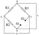
植入物本体内部设置有模拟开关、电桥以及通信模块,测量点由引线接入模拟开关的输入端,模拟开关的输出端接入电桥,所述电桥用来测量两相邻测量点之间的电阻数据,并将电阻数据通过通信模块发送给外部终端。The implant body is equipped with an analog switch, an electric bridge and a communication module. The measurement point is connected to the input end of the analog switch by a lead wire, and the output end of the analog switch is connected to the electric bridge. The electric bridge is used to measure two adjacent measurement points. The resistance data between them, and send the resistance data to the external terminal through the communication module.
植入物可以为螺钉,所述螺钉螺纹之间的沟槽表面设置有压敏层,所述压敏层紧贴在螺纹之间的沟槽表面。The implant can be a screw, and the surface of the groove between the threads of the screw is provided with a pressure-sensitive layer, and the pressure-sensitive layer is closely attached to the surface of the groove between the threads.
植入物可以为膝关节假体,所述膝关节假体的垫片表面设置有压敏层,所述压敏层设置在膝关节假体的垫片与膝关节假体中的股骨组件接触的位置。The implant can be a knee joint prosthesis, the surface of the gasket of the knee joint prosthesis is provided with a pressure-sensitive layer, and the pressure-sensitive layer is arranged on the pad of the knee joint prosthesis in contact with the femoral component in the knee joint prosthesis s position.
植入物可以为踝关节假体,所述踝关节假体的垫片表面设置有压敏层。The implant may be an ankle prosthesis, the spacer surface of which is provided with a pressure sensitive layer.
植入物可以为接骨板,所述接骨板螺孔之间的表面设置有压敏层。The implant can be a bone plate, and the surface between the screw holes of the bone plate is provided with a pressure-sensitive layer.
植入物可以为髋关节假体,所述髋关节假体的球体表面设置有压敏层,所述压敏层设置在髋关节假体的球体与髋关节假体内衬接触的表面。The implant may be a hip joint prosthesis, the spherical surface of the hip joint prosthesis is provided with a pressure-sensitive layer, and the pressure-sensitive layer is provided on the surface where the spherical body of the hip joint prosthesis is in contact with the lining of the hip joint prosthesis.
植入物可以为肩关节假体,所述肩关节假体的球体表面设置有压敏层,所述压敏层设置在肩关节假体的球体与肩关节假体内衬接触的表面。The implant can be a shoulder joint prosthesis, the surface of the spherical body of the shoulder joint prosthesis is provided with a pressure-sensitive layer, and the pressure-sensitive layer is disposed on the surface where the spherical body of the shoulder joint prosthesis is in contact with the lining of the shoulder joint prosthesis.
植入物可以为腕关节假体,所述腕关节假体的球体表面设置有压敏层,所述压敏层设置在腕关节假体的球体与腕关节假体内衬接触的表面。The implant may be a wrist joint prosthesis, a pressure-sensitive layer is provided on the surface of the sphere of the wrist joint prosthesis, and the pressure-sensitive layer is provided on the surface where the sphere of the wrist joint prosthesis is in contact with the lining of the wrist joint prosthesis.
植入物可以为髓内棒,所述髓内棒螺孔之间的表面设置有压敏层,压敏层为压敏薄膜带,所述压敏薄膜带两端设置有电流注入点。The implant can be an intramedullary rod, and the surface between the screw holes of the intramedullary rod is provided with a pressure-sensitive layer, the pressure-sensitive layer is a pressure-sensitive film strip, and current injection points are provided at both ends of the pressure-sensitive film strip.
植入物可以为钉棒系统,钉棒系统包括螺钉以及棒,所述螺钉螺纹之间的凹槽中设置有压敏层,所述棒的螺孔之间的表面设置有压敏层。The implant may be a screw-and-rod system, which includes screws and rods, a pressure-sensitive layer is provided in the groove between the screw threads, and a pressure-sensitive layer is provided on the surface between the screw holes of the rod.
植入物可以为骨科固定支架,所述骨科固定支架包括固定钢针以及固定连杆,所述固定钢针表面设置有压敏层,所述固定连杆表面设置有压敏层。The implant can be an orthopedic fixation bracket, and the orthopedic fixation bracket includes a fixed steel needle and a fixed connecting rod, the surface of the fixed steel needle is provided with a pressure-sensitive layer, and the surface of the fixed connecting rod is provided with a pressure-sensitive layer.
植入物可以为人工椎体,所述人工椎体表面设置有压敏层。The implant can be an artificial vertebral body, and the surface of the artificial vertebral body is provided with a pressure-sensitive layer.
植入物可以为椎间融合器,所述椎间融合器表面设置有压敏层。The implant may be an intervertebral fusion cage, the surface of which is provided with a pressure sensitive layer.
智能骨科植入物监测系统,包括智能终端以及上述所述的智能骨科植入物,所述智能终端用于根据电压或电阻数据对植入物的受力情况进行分析,判断出植入物当前的状态并根据植入物状态进行相应预警提示。The intelligent orthopedic implant monitoring system includes an intelligent terminal and the above-mentioned intelligent orthopedic implant, and the intelligent terminal is used to analyze the force of the implant according to the voltage or resistance data, and determine the current state of the implant. The state of the implant and the corresponding warning prompt according to the state of the implant.
智能骨科植入物监测系统的一种实施例结构框图如图15所示,恒流源为压敏层提供电流,电压测量模块实时测量压敏层测量点之间的电压,并将电压信息发送给通信模块,通信模块将电压信息发送给终端进行数据监控分析,判断螺钉的状态;电源模块用于为电压测量模块以及通信模块提供电源。A structural block diagram of an embodiment of an intelligent orthopedic implant monitoring system is shown in Figure 15. The constant current source provides current for the pressure-sensitive layer, and the voltage measurement module measures the voltage between the measurement points of the pressure-sensitive layer in real time and sends the voltage information to To the communication module, the communication module sends the voltage information to the terminal for data monitoring and analysis, and judges the status of the screw; the power module is used to provide power for the voltage measurement module and the communication module.
智能骨科植入物状态判断方法,应用于上述所述的智能骨科植入物监测系统,包括:The method for judging the state of an intelligent orthopedic implant is applied to the above-mentioned intelligent orthopedic implant monitoring system, including:
实时监测各相邻测量点之间的电压或电阻,若任意相邻测量点之间的电压或电阻不等于各相邻测量点对应的初始电压或电阻,则判定植入物出现了松动或弯曲或断裂。Monitor the voltage or resistance between adjacent measurement points in real time. If the voltage or resistance between any adjacent measurement points is not equal to the initial voltage or resistance corresponding to each adjacent measurement point, it is determined that the implant has loosened or bent or break.
所述判断植入物出现松动的方法具体包括:The method for judging that the implant is loose specifically includes:
实时监测各相邻测量点之间的电压或电阻,若任意相邻测量点之间的电压值或电阻值在设定观察时间内出现了持续性的降低,则判定植入物出现了松动,并进行植入物松动提示。Monitor the voltage or resistance between adjacent measurement points in real time. If the voltage or resistance value between any adjacent measurement points decreases continuously within the set observation time, it is determined that the implant is loose. And prompt for implant loosening.
若任意相邻测量点之间的电压值降低到初始电压值,则进行预警。If the voltage value between any adjacent measurement points drops to the initial voltage value, an early warning will be given.
判定植入物出现弯曲的具体方法包括:Specific methods for identifying bowed implants include:
计算各相邻测量点当前电压或电阻与各相邻测量点对应的初始电压或电阻的差值,若最大电压或电阻差大于第一阈值电压或电阻并且小于第二阈值电压或电阻,则判定植入物出现了弯曲;Calculate the difference between the current voltage or resistance of each adjacent measurement point and the initial voltage or resistance corresponding to each adjacent measurement point, if the maximum voltage or resistance difference is greater than the first threshold voltage or resistance and less than the second threshold voltage or resistance, then judge The implant is bent;
所述第二阈值电压或电阻大于第一阈值电压或电阻。The second threshold voltage or resistance is greater than the first threshold voltage or resistance.
若判定植入物出现弯曲,则实时记录植入物的弯曲变形量以及对应发生的时间,然后根据植入物在对应时间内的弯曲变形量判定骨头生长愈合情况。If it is determined that the implant is bent, record the amount of bending deformation of the implant and the corresponding occurrence time in real time, and then determine the bone growth and healing according to the amount of bending deformation of the implant within the corresponding time.
判定植入物出现断裂的具体方法包括:Specific methods for determining if an implant has fractured include:
若最大电压或电阻差持续增加到大于第二阈值电压或电阻后,在设置时间内出现了各相邻测量点当前电压或电阻为零的情况,则判定植入物出现了断裂。If the maximum voltage or resistance difference continues to increase to be greater than the second threshold voltage or resistance, and the current voltage or resistance of each adjacent measurement point is zero within the set time, it is determined that the implant is broken.
实施案例1:植入物为螺钉,螺钉通常用于将钢板等外固定与骨连接或者将骨折块连接起来;应用于稳定新的骨折、翻修手术、关节融合、以及重建足,脚踝和脚趾的小骨;例如:髁、踝、粗隆或结节的撕裂骨折(如股、胫骨内、外髁骨折,踝部骨折,尺骨鹰嘴突骨折、肱骨大结节骨折,胫骨结节骨折等),特别是累及关节面者。这些骨折的骨片小,肌牵引力较大,易移位,外固定难以达到保持复位的目的,螺钉固定最为合适;或手法复位失败的长骨螺旋骨折、长斜骨折以及蝶形骨折;或股骨颈基底部骨折,使用加压松质骨螺钉加垫圈固定,可以起固定与加压双重作用。Implementation case 1: The implant is a screw, which is usually used to connect external fixation such as a plate to the bone or to connect the fracture fragments; it is used to stabilize new fractures, revision surgery, joint fusion, and reconstruction of feet, ankles and toes Small bones; for example: avulsion fractures of the condyle, ankle, tuberosity or tuberosity (such as femoral, tibial medial and lateral condyle fractures, ankle fractures, olecranon process fractures, greater tuberosity fractures of the humerus, tibial tuberosity fractures, etc.) , especially those involving the articular surfaces. The bone fragments of these fractures are small, the muscle traction force is large, and they are easy to shift. External fixation is difficult to achieve the purpose of maintaining reduction, and screw fixation is the most suitable; or long bone spiral fractures, long oblique fractures, and butterfly fractures that fail manual reduction; or femoral neck For basal fractures, compression cancellous bone screws and washers are used for fixation, which can play a dual role of fixation and compression.
根据结构设计可以分为普通螺钉、锁定螺钉、无头螺钉以及空心螺钉等;According to the structural design, it can be divided into ordinary screws, locking screws, headless screws and hollow screws, etc.;
根据材料可以分为钛钉、不锈钢钉以及生物可吸收螺钉;According to the material, it can be divided into titanium nails, stainless steel nails and bioabsorbable screws;
根据应用部位可以分为皮质骨螺钉、松质骨螺钉;According to the application site, it can be divided into cortical bone screws and cancellous bone screws;
根据螺钉功能可以分为钢板螺钉、拉力螺钉、位置螺钉、交锁钉、复位螺钉等;According to the screw function, it can be divided into plate screw, lag screw, position screw, interlocking screw, reset screw, etc.;
其中皮质骨螺钉全长都有螺纹,通常有下列直径:4.5mm、3.5mm、2.7mm、2mm和1.5mm。皮质骨螺钉可用作位置螺钉也可用作拉力螺钉。在用作拉力螺钉时,将近侧皮质扩孔,即可在骨折块间产生加压作用。Among them, cortical bone screws are threaded throughout their length and usually have the following diameters: 4.5mm, 3.5mm, 2.7mm, 2mm and 1.5mm. Cortical screws can be used as both position and lag screws. When used as a lag screw, the proximal cortex is reamed to create compression between the fracture fragments.
松质骨螺钉有较大的螺纹,可以更牢固地抓住较软的骨松质,因此更常被用于干骺端。松质骨螺钉有6.5mrn和4mm两种直径、螺纹长度有16mm和32mm两种。空心骨松质螺钉有6.5mm、7.0mm、7.3mm直径,螺纹长度有16mm和32mm两种。无论螺钉有多长,只有这两种螺纹长度。踝螺钉为一种4.5mm螺钉,也包括在此组螺钉内,但它是唯一具有自攻环钻钉尖(self-tapping trephine tip)的螺钉。选择正确的直径钻头,并钻孔攻丝是确保螺钉固定牢固的关键。这类螺钉通常要用塑料和金属垫圈,以便重新连接撕裂韧带或通过为螺钉提供较大的压迫骨皮质的接触面。以给骨折块加压。Cancellous screws have larger threads for a firmer grip on the softer cancellous bone and are therefore more commonly used in the metaphysis. Cancellous bone screws have two diameters of 6.5mrn and 4mm, and two thread lengths of 16mm and 32mm. Hollow bone cancellous screws have diameters of 6.5mm, 7.0mm, and 7.3mm, and thread lengths of 16mm and 32mm. No matter how long the screw is, there are only two thread lengths. The ankle screw, a 4.5mm screw, was also included in this set, but it was the only one with a self-tapping trephine tip. Selecting the correct diameter drill bit, and drilling and tapping are the keys to ensure the screw is firmly fixed. These screws are usually used with plastic and metal washers in order to reattach the torn ligament or by providing the screw with a large contact surface that compresses the cortical bone. to apply pressure to the fractured fragment.
锁定螺钉是钉帽带有螺纹的自攻螺钉,其安装时需要精确的预钻孔。从而与钢板锁定,才能达到紧密固定,置入时需要特殊的改锥。Locking screws are self-tapping screws with a threaded cap that require precise pre-drilled holes for installation. In order to achieve tight fixation by locking with the steel plate, a special screwdriver is required for insertion.
拉力螺钉又称半螺纹螺钉,所起的作用不是特指某一种螺钉,可以是空心螺钉也可以是普通螺钉,股骨颈骨折一般使用空心螺钉进行固定,同时要求具有拉力,在骨片间加压的最有效的方式是使用拉力螺钉,拉力螺钉的方向垂直骨折线,可带来最大的折块间加压,大部分情况下可以达到拉力螺钉的最佳功能,当螺钉不与骨折线垂直时,在拧紧时会产生剪力使骨折块移位。Lag screws, also known as half-thread screws, do not specifically refer to a certain type of screw. They can be hollow screws or ordinary screws. Hollow screws are generally used for femoral neck fractures. At the same time, tension is required. The most effective way to compress is to use a lag screw. The direction of the lag screw is perpendicular to the fracture line, which can bring about the greatest interfragmentary compression. In most cases, the best function of the lag screw can be achieved when the screw is not perpendicular to the fracture line. When tightening, shear forces are generated to displace the fracture fragments.
另外还有一种特殊的种植牙螺钉。种植牙螺钉是一种特殊的螺钉,常用于口腔修复外科,是一种以植入骨组织内的下部结构为基础来支持、固位上部牙修复体的缺牙修复方式。它包括下部的支持种植体(dental implant)和上部的牙修复体(dentalprosthesis,implant-supported)两部分。它采用人工材料(如金属、陶瓷等)制成种植体(一般类似牙根形态),经手术方法植入组织内(通常是上下颌)并获得骨组织牢固的固位支持,通过特殊的装置和方式连接支持上部的牙修复体。种植牙螺钉并发症主要包括种植体及修复体相关的螺丝、基台、种植体折断、修复体损坏等。There is also a special implant screw. Dental implant screw is a special kind of screw, which is often used in restorative oral surgery. It is a kind of edentulous restoration method based on the lower structure implanted in bone tissue to support and retain the upper tooth restoration. It includes two parts, the lower support implant (dental implant) and the upper dental restoration (dental prosthesis, implant-supported). It uses artificial materials (such as metal, ceramics, etc.) to make implants (generally similar to the shape of tooth roots), which are surgically implanted into tissues (usually the upper and lower jaws) and obtain firm retention support from bone tissue. Through special devices and way to connect and support the upper part of the dental restoration. Implant screw complications mainly include implant and restoration-related screws, abutment, implant fracture, and restoration damage.
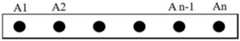
在螺钉上设置压敏层的实施例如图1,可在螺钉螺纹之间的沟槽表面设置有压敏层,所述压敏层紧贴在螺纹之间的沟槽表面,测量点均与分布在压敏层上,相邻沟槽均设置等间距分布测量点201,螺杆上螺纹的起始位置以及螺杆尾部均设置一个电流注入点101,通过电流注入点接入恒流。The embodiment of setting the pressure-sensitive layer on the screw is shown in Figure 1. The pressure-sensitive layer can be arranged on the surface of the groove between the screw threads, and the pressure-sensitive layer is close to the surface of the groove between the threads, and the measurement points are all in line with the distribution On the pressure-sensitive layer, adjacent grooves are provided with equally spaced measuring points 201, and a
恒流源、电压测量模块以及通信模块安装在螺钉内部。The constant current source, voltage measurement module and communication module are installed inside the screw.
恒流源用于为压敏层提供电流,所述电压测量模块用于实时测量任意两个相邻测量点之间的电压数据,并将电压数据通过通信模块发送给智能终端。The constant current source is used to provide current for the pressure-sensitive layer, and the voltage measurement module is used to measure the voltage data between any two adjacent measurement points in real time, and send the voltage data to the smart terminal through the communication module.
智能终端实时监测各相邻测量点之间的电压,若任意相邻测量点之间的电压不等于各相邻测量点对应的初始电压,则判定螺钉出现了松动或弯曲或断裂。The smart terminal monitors the voltage between adjacent measurement points in real time. If the voltage between any adjacent measurement points is not equal to the initial voltage corresponding to each adjacent measurement point, it is determined that the screw is loose or bent or broken.
两个测量点之间的等效电阻为:R=ρL/S,ρ表示压敏金属的电阻率,L表示两测量点之间压敏薄膜带的长度,S表示压敏薄膜的横截面积。压敏薄膜带受力示意图如图14,当受力F时,其长度保持不变,但其横截面积会减小,从而导致两点间的等效电阻变大,相邻两个测量点的电压就会增大。The equivalent resistance between two measurement points is: R=ρL/S, ρ represents the resistivity of the pressure-sensitive metal, L represents the length of the pressure-sensitive film strip between the two measurement points, and S represents the cross-sectional area of the pressure-sensitive film . The force diagram of the pressure-sensitive film belt is shown in Figure 14. When the force F is applied, its length remains unchanged, but its cross-sectional area will decrease, resulting in an increase in the equivalent resistance between two points. Two adjacent measurement points voltage will increase.
当螺钉植入体内后,由于螺钉表面分布有若干测量点,测量点的电压可以准确表征该处的受力情况,将电压数据表征为受力数据,就能得到测量点的受力示意图。When the screw is implanted in the body, since there are several measuring points distributed on the surface of the screw, the voltage at the measuring point can accurately represent the stress situation at the place, and the voltage data can be represented as force data, and the force schematic diagram of the measuring point can be obtained.
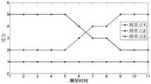
当螺钉发生松动,螺钉受力位置或受力大小的变化情况如图24所示,测量点1的受力逐渐减小,则代表该处发生了松动;测量点2的受力增大,则代表螺钉紧固位置发生了变化;测量点3的受力保持不变,表示该处无变化。螺钉松动,一般会发生类似于测量点1的受力情况,可能会伴随类似于受力点2的受力情况。When the screw loosens, the position or magnitude of the screw’s force is shown in Figure 24. The force on measuring
当螺钉发生弯曲时,其受力示意图如图25所示,由于螺钉的表面都设置有压敏带,会造成弯曲处某一侧压敏薄膜带拉伸而另一侧压敏薄膜带压缩,导致发生拉伸的压敏薄膜带测量值增大,而发生压缩的压敏薄膜带测量值减小。When the screw is bent, its stress diagram is shown in Figure 25. Since the surface of the screw is provided with a pressure-sensitive tape, the pressure-sensitive film tape on one side of the bend will be stretched and the pressure-sensitive film tape on the other side will be compressed. This results in an increase in the measured value for the stretched pressure sensitive film tape and a decreased measured value for the compressed pressure sensitive film tape.
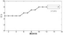
当螺钉某处发生了断裂,其受力示意图如图26所示,会导致该处的压敏带也一同断裂,导致无法检测到测量信号。而且一般螺钉断裂,会有一个受力拉伸然后再断裂的过程,因此测量信号会逐渐增大,然后突然消失。When a screw breaks somewhere, its stress schematic diagram is shown in Figure 26, which will cause the pressure-sensitive belt at this place to break together, making it impossible to detect the measurement signal. Moreover, when a screw breaks, there will be a process of stretching under force and then breaking, so the measurement signal will gradually increase and then disappear suddenly.
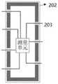
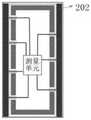
图16为螺钉内部第一结构示意图,螺钉做成内腔中空结构,在测量点201处预设孔洞。FIG. 16 is a schematic diagram of the first internal structure of the screw. The screw is made into a hollow structure with a preset hole at the
图17为螺钉内部第二结构示意图,利用真空蒸镀工艺,在螺钉表面蒸镀上一层惰性(非金属)保护层202(厚度约几十纳米)。FIG. 17 is a schematic diagram of the second internal structure of the screw. A layer of inert (non-metallic) protective layer 202 (with a thickness of about tens of nanometers) is evaporated on the surface of the screw by vacuum evaporation process.
图18为螺钉内部第三结构示意图,在螺钉内部设置MEMS测量单元,测量单元的测量引线203从孔洞内穿出。FIG. 18 is a schematic diagram of a third internal structure of the screw. A MEMS measurement unit is arranged inside the screw, and the measurement leads 203 of the measurement unit pass through the hole.
图19为螺钉内部第四结构示意图,在惰性保护层202上,利用溅射工艺,溅射上一层金属薄膜,然后再用电化学沉积工艺,在金属薄膜上沉积一层厚度可控的金属敏感层,测量引线与金属敏感层融合为一体。Fig. 19 is a schematic diagram of the fourth internal structure of the screw. On the inert
图20为螺钉内部第五结构示意图,最后再利用真空蒸镀工艺,在整个螺钉外表面蒸镀上一层惰性保护层202,该保护层具备耐磨、抗拉伸及抗剪切力的功能。Figure 20 is a schematic diagram of the fifth internal structure of the screw. Finally, a layer of inert
实施例2:植入为髋关节假体,其结构示意图如图5所示,包括臼杯5、内衬8、球体6以及股骨柄7,球体6可拆卸更换,内衬8嵌套在臼杯5中,球体6可在内衬8中自由转动;压敏薄膜带100紧贴在球体6与髋关节假体内衬接触的表面,压敏薄膜带100上等间距分布有多个测量点201,并且压敏薄膜带两端设置电流注入点101。Embodiment 2: Implanted as a hip joint prosthesis, its structural schematic diagram is shown in Figure 5, including an
电流注入点接入恒流源,恒流源用于为压敏层提供电流,电压测量模块实时测量任意两个相邻测量点之间的电压数据,并将电压数据通过通信模块发送给智能终端,通信模块以及电压测量模块可以设置在球体中。The current injection point is connected to the constant current source, and the constant current source is used to provide current for the pressure-sensitive layer. The voltage measurement module measures the voltage data between any two adjacent measurement points in real time, and sends the voltage data to the smart terminal through the communication module , the communication module and the voltage measurement module can be arranged in the sphere.
智能终端用于根据电压数据对髋关节假体的受力情况进行分析,判断出髋关节假体当前的状态并根据髋关节假体状态进行相应预警提示。The smart terminal is used to analyze the force of the hip joint prosthesis according to the voltage data, judge the current state of the hip joint prosthesis, and give corresponding warning prompts according to the state of the hip joint prosthesis.
髋关节假体状态判断方法包括:实时监测各相邻测量点之间的电压,若任意相邻测量点之间的电压不等于各相邻测量点对应的初始电压,则判定髋关节假体出现了松动或弯曲或断裂。The method for judging the state of the hip joint prosthesis includes: monitoring the voltage between adjacent measurement points in real time, and if the voltage between any adjacent measurement points is not equal to the initial voltage corresponding to each adjacent measurement point, then it is determined that the hip joint prosthesis is present. loose or bent or broken.
判断髋关节假体出现松动的方法具体包括:The methods for judging the loosening of hip prosthesis include:
实时监测各相邻测量点之间的电压,若任意相邻测量点之间的电压值在设定观察时间内出现了持续性的降低,则判定髋关节假体出现了松动,并进行髋关节假体松动提示。其中髋关节假体出现了松动主要指球体6与内衬8之间出现了松动。当球体6与内衬8之间松动时,压敏薄膜带的受力就会减小,横截面积会相应增加,任意两测量点之间的电阻就会变小,相应电压就会减小。Monitor the voltage between adjacent measurement points in real time. If the voltage value between any adjacent measurement points decreases continuously within the set observation time, it is determined that the hip joint prosthesis is loose, and the hip joint prosthesis is determined to be loose. Prosthetic loosening reminder. The loosening of the hip joint prosthesis mainly refers to the loosening between the
若任意相邻测量点之间的电压值降低到初始电压值,则进行预警。If the voltage value between any adjacent measurement points drops to the initial voltage value, an early warning will be given.
判定髋关节假体出现弯曲的方法包括:Methods for identifying flexion in a hip prosthesis include:
计算各相邻测量点当前电压与各相邻测量点对应的初始电压的差值,若最大电压差大于第一阈值电压并且最大电压差小于第二阈值电压,则判定髋关节假体出现了弯曲;Calculate the difference between the current voltage of each adjacent measurement point and the initial voltage corresponding to each adjacent measurement point. If the maximum voltage difference is greater than the first threshold voltage and the maximum voltage difference is less than the second threshold voltage, it is determined that the hip joint prosthesis is bent ;
所述第二阈值电压大于第一阈值电压;初始电压为髋关节假体植入人体时,两测量点之间的电压值。The second threshold voltage is greater than the first threshold voltage; the initial voltage is the voltage value between two measurement points when the hip joint prosthesis is implanted into the human body.
若判定髋关节假体出现弯曲,则实时记录髋关节假体的弯曲变形量以及对应发生的时间,然后根据髋关节假体在对应时间内的弯曲变形量判定骨头生长愈合情况。If it is determined that the hip joint prosthesis is bent, record the amount of bending deformation of the hip joint prosthesis and the corresponding occurrence time in real time, and then judge the bone growth and healing according to the amount of bending deformation of the hip joint prosthesis within the corresponding time.
判定髋关节假体出现断裂的方法包括:Methods for identifying a fractured hip prosthesis include:
若最大电压差持续增加到大于第二阈值电压后,在设置时间内出现了各相邻测量点当前电压为零的情况,则判定髋关节假体出现了断裂。If the maximum voltage difference continues to increase to be greater than the second threshold voltage, and the current voltage of each adjacent measurement point is zero within the set time, it is determined that the hip joint prosthesis is broken.
实施案例3:植入物为膝关节假体,膝关节假体的结构示意图如图2,包括股骨组件1、胫骨组件3、垫片(即人工半月板)2以及髌骨组件(股骨假体1的背面);Implementation case 3: The implant is a knee joint prosthesis. The structural schematic diagram of the knee joint prosthesis is shown in Figure 2, including a
股骨组件1:这块金属与股骨末端相连。它有一个凹槽,允许髌骨组件在膝盖弯曲和伸直时平稳地上下滑动。Femoral Component 1: This piece of metal attaches to the end of the femur. It has a groove that allows the patella component to slide up and down smoothly as the knee flexes and straightens.
垫片2:垫片为偏平,两件金属和聚乙烯(塑料)部分附着在胫骨上。金属部分位于胫骨的顶部,并有一个茎插进入胫骨以保持稳定。可塑部分,或称为胫骨垫片,在金属胫骨假体和金属股骨假体之间起缓冲作用。Spacer 2: The spacer is a flat, two piece metal and polyethylene (plastic) part attached to the tibia. The metal part sits on top of the tibia and has a stem inserted into the tibia for stability. The plastic part, or tibial spacer, acts as a cushion between the metal tibial component and the metal femoral component.
髌骨组件:这块塑料片是圆顶状的以匹配髌骨表面的形状。因为髌骨靠在股骨上,髌骨组件和股骨组件的对齐对正常功能至关重要。髌骨由股四头肌腱和髌骨肌腱固定。Patellar Component: This piece of plastic is domed to match the shape of the surface of the patella. Because the patella rests on the femur, alignment of the patellar and femoral components is critical for proper function. The patella is secured by the quadriceps and patella tendons.
上述组件及垫片通常都是用骨水泥固定的,但是一些医生使用一种无骨水泥的技术来帮助骨生长到植入物中以增加稳定性。无骨水泥技术可用于年轻、健康、膝关节周围骨骼结构强健的患者。因为骨水泥会脱落,导致假体松动,无骨水泥的膝关节置换术随着时间的推移不太可能松动。因此,人们认为骨水泥膝关节置换术更适合年纪较大、活动度较低的患者。These components and spacers are usually cemented, but some doctors use a cementless technique to help the bone grow into the implant for added stability. Cementless techniques can be used in young, healthy patients with strong bone structure around the knee joint. Because the cement can break off, causing the prosthesis to loosen, cementless knee replacements are less likely to loosen over time. Therefore, cemented knee arthroplasty is considered more appropriate for older, less mobile patients.
膝关节假体按材料可以分为如下类型:Knee prostheses can be divided into the following types according to the material:
Metal on plastic:最常见的一种植入物。其特点是金属股假体附着在与胫骨假体相连的聚乙烯塑料垫片上。常用的金属有钴、铬、钛、锆以及镍。金属对塑料是最便宜的一种植入物,在安全性和植入物寿命方面有着最长的记录。然而,塑料植入物可能会出现一个问题,那就是由衬垫磨损的微小颗粒引发的免疫反应。这会导致骨头破裂,导致种植体松动和失败。制造的进步大大降低了塑料的磨损率。Metal on plastic: The most common type of implant. It features a metal femoral component attached to a polyethylene plastic spacer attached to the tibial component. Commonly used metals are cobalt, chromium, titanium, zirconium and nickel. Metal-on-plastic is the cheapest type of implant and has the longest track record for safety and implant longevity. One problem that may arise with plastic implants, however, is the immune response triggered by the tiny particles that wear away from the liners. This can cause the bone to break, causing the implant to loosen and fail. Advances in manufacturing have greatly reduced the wear rate of plastics.
Ceramic on plastic:这种类型使用陶瓷假体代替金属假体(或带陶瓷涂层的金属假体)。它还安装在一个塑料垫片上。对金属植入物中的镍敏感的人可能会选择陶瓷植入物。这种植入物的塑料颗粒也会导致免疫反应。Ceramic on plastic: This type uses a ceramic prosthesis instead of a metal prosthesis (or a ceramic-coated metal prosthesis). It also mounts on a plastic spacer. People who are sensitive to nickel in metal implants may choose ceramic implants. Plastic particles from such implants can also cause an immune response.
Ceramic on ceramic:股骨和胫骨假体都是陶瓷做的。陶瓷部件最不可能与身体发生反应。然而,陶瓷关节假体在走路时会发出吱吱声。在极少数情况下,它们会在重压下碎裂成碎片,必须通过手术移除。Ceramic on ceramic: Both the femoral and tibial prostheses are made of ceramic. Ceramic parts are the least likely to react with the body. However, ceramic joint prostheses can squeak when you walk. In rare cases, they shatter into pieces under the weight and must be surgically removed.
Metal on metal:股骨和胫骨假体都是金属做的。近年来,金属对金属植入物的使用越来越少,因为人们担心微量金属会渗漏到血液中。金属来自于植入物的化学分解。所有的金属植入物最初都是为年轻人提供更持久的关节置换。但是微量的金属会引起炎症,疼痛,甚至器官损伤。育龄妇女不能接受这些植入物,因为对胎儿的影响尚不清楚。Metal on metal: Both the femoral and tibial prostheses are made of metal. Metal-on-metal implants have been used less and less in recent years because of concerns that trace amounts of the metal could leak into the bloodstream. The metal comes from the chemical breakdown of the implant. All metal implants were originally developed to provide longer-lasting joint replacements in young adults. But trace amounts of the metal can cause inflammation, pain, and even organ damage. Women of childbearing age cannot receive these implants because the effects on the fetus are unknown.
可在上述膝关节假体的垫片表面设置压敏薄膜带100,设置方式如图2垫片所示,压敏薄膜带100可设置在膝关节假体的垫片2与膝关节假体中的股骨组件接触的表面,也可以设置在垫片2与胫骨组件3接触的表面,压敏薄膜带100的两端设置均设置电流注入点101。A pressure-
恒流源、电压测量模块以及通信模块可集成设置在垫片2中,恒流源用于为压敏层提供电流,所述电压测量模块用于实时测量压敏层上任意两个相邻测量点之间的电压数据,并将电压数据通过通信模块发送给智能终端。The constant current source, the voltage measurement module and the communication module can be integrated in the
智能终端用于根据电压数据对膝关节假体的受力情况进行分析,判断出膝关节假体当前的状态并根据膝关节假体状态进行相应预警提示。The smart terminal is used to analyze the force of the knee prosthesis according to the voltage data, judge the current state of the knee prosthesis and give corresponding warning prompts according to the state of the knee prosthesis.
膝关节假体状态判断方法包括:实时监测各相邻测量点之间的电压,若任意相邻测量点之间的电压不等于各相邻测量点对应的初始电压,则判定膝关节假体出现了松动或弯曲或断裂。The method for judging the state of the knee prosthesis includes: monitoring the voltage between adjacent measurement points in real time, and if the voltage between any adjacent measurement points is not equal to the initial voltage corresponding to each adjacent measurement point, it is determined that the knee joint prosthesis is present. loose or bent or broken.
判断膝关节假体出现松动的方法具体包括:The methods for judging the loosening of the knee prosthesis include:
实时监测各相邻测量点之间的电压,若任意相邻测量点之间的电压值在设定观察时间内出现了持续性的降低,则判定膝关节假体出现了松动,并进行膝关节假体松动提示。其中膝关节假体出现了松动主要指垫片2与股骨组件1或胫骨组件3的接触面出现了松动。当上述部位出现松动时,压敏薄膜带的受力就会减小,横截面积会相应增加,任意两测量点之间的电阻就会变小,相应电压就会减小。Monitor the voltage between adjacent measurement points in real time. If the voltage value between any adjacent measurement points decreases continuously within the set observation time, it is determined that the knee joint prosthesis is loose, and the knee joint prosthesis is determined to be loose. Prosthetic loosening reminder. The looseness of the knee joint prosthesis mainly refers to the loosening of the contact surface between the
若任意相邻测量点之间的电压值降低到初始电压值,则进行预警。If the voltage value between any adjacent measurement points drops to the initial voltage value, an early warning will be given.
判定膝关节假体出现弯曲的方法包括:Methods for determining knee prosthesis flexion include:
计算各相邻测量点当前电压与各相邻测量点对应的初始电压的差值,若最大电压差大于第一阈值电压并且最大电压差小于第二阈值电压,则判定膝关节假体出现了弯曲;Calculate the difference between the current voltage of each adjacent measurement point and the initial voltage corresponding to each adjacent measurement point, if the maximum voltage difference is greater than the first threshold voltage and the maximum voltage difference is less than the second threshold voltage, it is determined that the knee prosthesis is bent ;
所述第二阈值电压大于第一阈值电压;初始电压为膝关节假体植入人体时,测量点之间的电压值。The second threshold voltage is greater than the first threshold voltage; the initial voltage is the voltage value between measurement points when the knee joint prosthesis is implanted into the human body.
若判定膝关节假体出现弯曲,则实时记录膝关节假体的弯曲变形量以及对应发生的时间,然后根据膝关节假体在对应时间内的弯曲变形量判定骨头生长愈合情况。If it is determined that the knee prosthesis is bent, record the amount of bending deformation of the knee prosthesis and the corresponding occurrence time in real time, and then judge the bone growth and healing according to the amount of bending deformation of the knee prosthesis within the corresponding time.
判定膝关节假体出现断裂的方法包括:Methods for determining the fracture of a knee prosthesis include:
若最大电压差持续增加到大于第二阈值电压后,在设置时间内出现了各相邻测量点当前电压为零的情况,则判定膝关节假体出现了断裂。If the maximum voltage difference continues to increase to be greater than the second threshold voltage, and the current voltage of each adjacent measurement point is zero within the set time, it is determined that the knee joint prosthesis is broken.
实施案例4:植入物为踝关节假体,踝关节假体的结构示意图如图3,压敏薄膜带100设置在踝关节假体垫片2的上下表面,压敏薄膜带100的两端设置均设置电流注入点101。Implementation Case 4: The implant is an ankle joint prosthesis. The structural diagram of the ankle joint prosthesis is shown in Figure 3. The pressure-
垫片内部设置有恒流源、电压测量模块以及通信模块,恒流源用于为压敏层提供电流,电压测量模块用于实时测量任意两个相邻测量点之间的电压数据,并将电压数据通过通信模块发送给智能终端。The gasket is equipped with a constant current source, a voltage measurement module and a communication module. The constant current source is used to provide current for the pressure-sensitive layer, and the voltage measurement module is used to measure the voltage data between any two adjacent measurement points in real time, and the voltage The data is sent to the smart terminal through the communication module.
智能终端根据电压数据对踝关节假体的受力情况进行分析,判断出踝关节假体当前的状态并根据植入物状态进行相应预警提示。The smart terminal analyzes the force of the ankle prosthesis based on the voltage data, judges the current state of the ankle prosthesis, and gives corresponding warnings according to the implant status.
踝关节假体状态判断方法包括:实时监测各相邻测量点之间的电压,若任意相邻测量点之间的电压不等于各相邻测量点对应的初始电压,则判定踝关节假体出现了松动或弯曲或断裂。The method for judging the state of the ankle joint prosthesis includes: monitoring the voltage between adjacent measurement points in real time, and if the voltage between any adjacent measurement points is not equal to the initial voltage corresponding to each adjacent measurement point, then it is determined that the ankle joint prosthesis is present. loose or bent or broken.
判断踝关节假体出现松动的方法具体包括:The methods for judging the loosening of ankle prosthesis include:
实时监测各相邻测量点之间的电压,若任意相邻测量点之间的电压值在设定观察时间内出现了持续性的降低,则判定踝关节假体出现了松动,并进行踝关节假体松动提示。其中踝关节假体出现了松动主要指垫片2与其组件假体接触面出现了松动。当上述部位出现松动时,压敏薄膜带的受力就会减小,横截面积会相应增加,任意两测量点之间的电阻就会变小,相应电压就会减小。Monitor the voltage between adjacent measurement points in real time. If the voltage value between any adjacent measurement points decreases continuously within the set observation time, it is determined that the ankle joint prosthesis is loose, and the ankle joint prosthesis is determined to be loose. Prosthetic loosening reminder. The looseness of the ankle joint prosthesis mainly refers to the loosening of the contact surface between
若任意相邻测量点之间的电压值降低到初始电压值,则进行预警。If the voltage value between any adjacent measurement points drops to the initial voltage value, an early warning will be given.
判定踝关节假体出现弯曲的方法包括:Methods for identifying flexion in an ankle prosthesis include:
计算各相邻测量点当前电压与各相邻测量点对应的初始电压的差值,若最大电压差大于第一阈值电压并且最大电压差小于第二阈值电压,则判定踝关节假体出现了弯曲;Calculate the difference between the current voltage of each adjacent measurement point and the initial voltage corresponding to each adjacent measurement point. If the maximum voltage difference is greater than the first threshold voltage and the maximum voltage difference is less than the second threshold voltage, it is determined that the ankle prosthesis is bent ;
所述第二阈值电压大于第一阈值电压;初始电压为踝关节假体植入人体时,测量点之间的电压值。The second threshold voltage is greater than the first threshold voltage; the initial voltage is the voltage value between measurement points when the ankle joint prosthesis is implanted into the human body.
若判定踝关节假体出现弯曲,则实时记录踝关节假体的弯曲变形量以及对应发生的时间,然后根据踝关节假体在对应时间内的弯曲变形量判定骨头生长愈合情况。If it is determined that the ankle prosthesis is bent, record the amount of bending deformation of the ankle prosthesis and the corresponding occurrence time in real time, and then determine the bone growth and healing according to the amount of bending deformation of the ankle prosthesis within the corresponding time.
判定踝关节假体出现断裂的方法包括:Methods for determining the fracture of an ankle prosthesis include:
若最大电压差持续增加到大于第二阈值电压后,在设置时间内出现了各相邻测量点当前电压为零的情况,则判定踝关节假体出现了断裂。If the maximum voltage difference continues to increase to be greater than the second threshold voltage, and the current voltage of each adjacent measurement point is zero within the set time, it is determined that the ankle joint prosthesis is broken.
实施案例5:植入物为肩关节假体,其结构示意图如图6,压敏薄膜带100紧贴在肩关节假体的球体6与其内衬8接触的表面,所述压敏薄膜带100上等间距分布测量点201,两端设置电流注入点101。Implementation Case 5: The implant is a shoulder joint prosthesis, its structural schematic diagram is shown in Figure 6, and the pressure-
恒流源用于为压敏层提供电流,电压测量模块实时测量任意两个相邻测量点之间的电压数据,并将电压数据通过通信模块发送给智能终端,恒流源、通信模块以及电压测量模块可以设置在球体中。The constant current source is used to provide current for the pressure-sensitive layer. The voltage measurement module measures the voltage data between any two adjacent measurement points in real time, and sends the voltage data to the smart terminal through the communication module. The constant current source, the communication module and the voltage The measurement module can be arranged in a sphere.
智能终端用于根据电压数据对肩关节假体的受力情况进行分析,判断出肩关节假体当前的状态并根据肩关节假体状态进行相应预警提示。The smart terminal is used to analyze the stress of the shoulder joint prosthesis according to the voltage data, judge the current state of the shoulder joint prosthesis and give corresponding warning prompts according to the state of the shoulder joint prosthesis.
肩关节假体状态判断方法包括:实时监测各相邻测量点之间的电压,若任意相邻测量点之间的电压不等于各相邻测量点对应的初始电压,则判定肩关节假体出现了松动或弯曲或断裂。The method for judging the status of the shoulder joint prosthesis includes: monitoring the voltage between adjacent measurement points in real time, and if the voltage between any adjacent measurement points is not equal to the initial voltage corresponding to each adjacent measurement point, then it is determined that the shoulder joint prosthesis is present. loose or bent or broken.
所述判断肩关节假体出现松动的方法具体包括:The method for judging that the shoulder joint prosthesis is loose specifically includes:
实时监测各相邻测量点之间的电压,若任意相邻测量点之间的电压值在设定观察时间内出现了持续性的降低,则判定肩关节假体出现了松动,并进行肩关节假体松动提示。其中肩关节假体出现了松动主要指球体6与内衬8之间出现了松动。当球体6与内衬8之间松动时,压敏薄膜带的受力就会减小,横截面积会相应增加,任意两测量点之间的电阻就会变小,相应电压就会减小。Monitor the voltage between adjacent measurement points in real time. If the voltage value between any adjacent measurement points decreases continuously within the set observation time, it is determined that the shoulder joint prosthesis is loose, and the shoulder joint prosthesis should be performed. Prosthetic loosening reminder. The looseness of the shoulder joint prosthesis mainly refers to the looseness between the
若任意相邻测量点之间的电压值降低到初始电压值,则进行预警。If the voltage value between any adjacent measurement points drops to the initial voltage value, an early warning will be given.
判定肩关节假体出现弯曲的方法包括:Methods for identifying flexion in a shoulder prosthesis include:
计算各相邻测量点当前电压与各相邻测量点对应的初始电压的差值,若最大电压差大于第一阈值电压并且最大电压差小于第二阈值电压,则判定肩关节假体出现了弯曲;Calculate the difference between the current voltage of each adjacent measurement point and the initial voltage corresponding to each adjacent measurement point, if the maximum voltage difference is greater than the first threshold voltage and the maximum voltage difference is less than the second threshold voltage, it is determined that the shoulder joint prosthesis is bent ;
所述第二阈值电压大于第一阈值电压,初始电压为肩关节假体植入人体内部时两测量点之间对应的电压。The second threshold voltage is greater than the first threshold voltage, and the initial voltage is the corresponding voltage between the two measurement points when the shoulder joint prosthesis is implanted into the human body.
若判定肩关节假体出现弯曲,则实时记录肩关节假体的弯曲变形量以及对应发生的时间,然后根据肩关节假体在对应时间内的弯曲变形量判定骨头生长愈合情况。If it is determined that the shoulder joint prosthesis is bent, record the amount of bending deformation of the shoulder joint prosthesis and the corresponding occurrence time in real time, and then determine the bone growth and healing according to the amount of bending deformation of the shoulder joint prosthesis within the corresponding time.
判定肩关节假体出现断裂的方法包括:Methods for determining the fracture of a shoulder prosthesis include:
若最大电压差持续增加到大于第二阈值电压后,在设置时间内出现了各相邻测量点当前电压为零的情况,则判定肩关节假体出现了断裂。If the maximum voltage difference continues to increase to be greater than the second threshold voltage, and the current voltage of each adjacent measurement point is zero within the set time, it is determined that the shoulder joint prosthesis is broken.
实施案例6:植入物为腕关节假体,其结构示意图如图7,压敏薄膜带100紧贴在腕关节假体的球体6与其内衬8接触的表面,所述压敏薄膜带100上等间距分布测量点201,两端设置电流注入点101。通信模块以及电压测量模块可以设置在球体中,也可以设置在股柄中。Implementation Case 6: The implant is a wrist joint prosthesis, its structural schematic diagram is shown in Figure 7, and the pressure-
球体6内部设置有恒流源、电压测量模块以及通信模块,所述恒流源用于为压敏层提供电流,所述电压测量模块用于实时测量任意两个相邻测量点之间的电压数据,并将电压数据通过通信模块发送给智能终端。The inside of the
智能终端用于根据电压数据对腕关节假体的受力情况进行分析,判断出腕关节假体当前的状态并根据腕关节假体状态进行相应预警提示。The smart terminal is used to analyze the force of the wrist prosthesis according to the voltage data, judge the current state of the wrist prosthesis and give corresponding warning prompts according to the state of the wrist prosthesis.
实施案例7:植入物为接骨板,接骨板是带孔板状骨折内固定器件。临床上常与骨螺钉或接骨丝配合使用,分为普通接骨板和加压接骨板两类,根据不同用途可制成条形、Y形、L形、T形等,用于保护、加压、支撑、张力带以及桥接。Implementation case 7: the implant is a bone plate, and the bone plate is a plate-shaped fracture internal fixation device with holes. Clinically, it is often used in conjunction with bone screws or bone wires. It is divided into two types: common bone plate and compression bone plate. According to different purposes, it can be made into strip shape, Y shape, L shape, T shape, etc. for protection and compression , braces, tension straps and bridging.
适用于关节内骨折、简单的骨干骨折、多骨折块的骨骺部和骨干骨折、涉及到关节的干骺端多骨折块骨折、具有不同类型的多节段骨折、复杂的粉碎性骨折、假体周围骨折再修复以及老年骨质疏松患者。For intra-articular fractures, simple diaphyseal fractures, multifragmentary epiphyseal and diaphyseal fractures, metaphyseal multifragmentary fractures involving the joint, multisegmental fractures with different types, complex comminuted fractures, prostheses Peripheral fracture re-repair and elderly patients with osteoporosis.
常用的包括普通接骨板、管形钢板、重建钢板、预期塑形钢板(解剖钢板)、加压接骨板、LC-DCP(有限接触性动力加压钢板)、梯形加压钢板以及锁定钢板。Commonly used ones include plain plate, tubular plate, reconstruction plate, prospective shaping plate (anatomical plate), compression plate, LC-DCP (limited contact dynamic compression plate), trapezoidal compression plate, and locking plate.
普通接骨板的类型较多,多由钴铬合金制成,一般为直板,圆孔式,孔直径稍大于螺钉直径,固定后,钢板无话动余地,不利于骨折端靠拢,断面略呈弧形,加工简单,其中以Sherman板常用。普通接骨板板仅其骨折端固定作用,不起加压作用,固定骨干骨折,长度要求最好大于所固定骨干直径的4~5倍。骨折线两端分别以2~4枚螺钉固定,且应离开粉碎的骨折线,螺钉必须恰好穿过两侧皮质。接骨板根据固定部位强度的需要,设计出厚薄及长度不同的式样,分为上肢接骨板和下肢接骨板。前者以3.5mm螺钉固定,后者以4.5mm螺钉固定。There are many types of ordinary bone plates, most of which are made of cobalt-chromium alloy. They are generally straight plates with round holes. The diameter of the holes is slightly larger than that of the screws. Shape, simple processing, among which Sherman board is commonly used. Ordinary bone plate only fixes the fracture end, and does not have a pressurizing effect. It fixes the bone fracture, and the length requirement is preferably 4 to 5 times greater than the diameter of the fixed bone. The two ends of the fracture line are fixed with 2 to 4 screws respectively, and they should be away from the comminuted fracture line, and the screws must just pass through the cortex on both sides. Bone plates are designed in different thicknesses and lengths according to the strength of the fixed parts, and are divided into upper limb bone plate and lower limb bone plate. The former is fixed with 3.5mm screws, and the latter is fixed with 4.5mm screws.
管形钢板,有大号半管形钢板和小号1/3管形钢板两种,非常薄,可以用在只有很少的软组织覆盖的地方,如尺骨远端、鹰嘴、外踝,由于厚度有限使其不像其他钢板那样很好地抵抗弯曲力量,椭圆形的孔可以用于偏心螺钉的放置。Tubular plates, available in large semi-tubular plates and small 1/3 tubular plates, are very thin and can be used where there is little soft tissue coverage, such as the distal ulna, olecranon, and lateral malleolus, due to the thickness Limited so that it does not resist bending forces as well as other plates, the oval hole can be used for eccentric screw placement.
重建钢板,将钢板塑形成三维的形状比较困难,尤其要弯曲外侧时。重建钢板以孔间的切迹为特征,便于弯曲;特殊的弯曲器械可以完成钢板平面内的塑形;钢板上椭圆形的孔便于加压。重建钢板对于需要复杂三维成形解剖部位如髋臼骨折十分有用,推荐使用根据骨的形状直接成形的钢板,其变形抗力比较低。Reconstructing the plate and shaping the plate into a three-dimensional shape is difficult, especially when bending the outside. The reconstructed steel plate is characterized by notches between the holes, which are easy to bend; special bending instruments can complete the shaping in the plane of the steel plate; the oval holes on the steel plate are convenient for compression. Reconstruction plates are very useful for anatomical sites that require complex three-dimensional shaping, such as acetabular fractures. It is recommended to use plates that are directly formed according to the shape of the bone, and its deformation resistance is relatively low.
预期塑形钢板(解剖钢板),多种预期塑形钢板可以适应特殊解剖部位的准确的形状,常被用于骨骺骨折和干骺端骨折。钢板的形状使螺钉可以从不同的平面插入干骺端。不同形状的钢板可用于同一个解剖部位,选择哪种钢板取决于骨折的类型、手术路径和医师的喜好。它很少完全适合特定的解剖部位,经常需要进一步塑形。Prospective shaping plates (anatomical plates), a variety of anticipatory shaping plates that can be adapted to the exact shape of a particular anatomical site, are often used for epiphyseal and metaphyseal fractures. The shape of the plate allows screws to be inserted into the metaphysis from different planes. Plates of different shapes can be used in the same anatomical site, and which plate to choose depends on the type of fracture, surgical approach, and physician preference. It rarely fits perfectly to a specific anatomy and often requires further shaping.
加压接骨板,最早称为自动加压型或自身加压型接骨板(selfcompression boneplate),系利用钢板上的钉孔特殊结构进行加压。比如,动力加压接骨板(dynaminccompressionplate,DCP),在加压侧钻孔时,紧贴钉孔远心端,当旋紧螺钉时,借助螺钉帽之坡度在钉孔远心端斜坡上滑移,以推动该骨折段向中心滑动,达到轴向加压的目的。Compression bone plate, originally known as self-compression or self-compression bone plate (selfcompression bone plate), is to use the special structure of nail holes on the plate for compression. For example, when the dynamic compression plate (DCP) is drilled on the compression side, it is close to the distal end of the nail hole, and when the screw is tightened, it slides on the slope of the distal end of the nail hole with the help of the slope of the screw cap. , so as to push the fracture segment to slide toward the center to achieve the purpose of axial compression.
它是较常用的一种类型。根据螺钉旋入孔的位置不同,加压接骨板可以起到中和、加压和支持接骨板的作用。It is the more commonly used type. Depending on where the screw is screwed into the hole, the compression plate can neutralize, compress, and support the plate.
LC-DCP(有限接触性动力加压钢板),加压钢板会对骨膜血供产生不利的影响,如可能会引起严重的井发症。为了尽量减小其不利影响。发明了LC-DCP。这种钢板的下表面是特殊成形的,可以减少50%与骨的接触面积。其横断面使刚度更加平衡分布,并使螺钉孔不会因应力增加而引起置入失败。特殊的导钻可确保螺钉能够准确置入负荷位、中性位或支撑位。另外,通用导钻有助于个别螺钉的固定,因为通用调节导钻的外径与螺钉外径相等,螺钉孔内的螺纹楔子可受到保护。LC-DCP (Limited Contact Dynamic Compression Plate), the compression plate will adversely affect the periosteal blood supply, such as may cause severe wells. In order to minimize its adverse effects. LC-DCP was invented. The lower surface of this plate is specially shaped to reduce the contact area with bone by 50%. Its cross-section allows for a more balanced distribution of stiffness and prevents screw holes from increasing stress and causing insertion failure. Special drill guides ensure accurate placement of the screw in load, neutral or support positions. In addition, the universal guide drill facilitates the fixation of individual screws, because the outer diameter of the universal adjustment guide drill is equal to the outer diameter of the screw, and the threaded wedge in the screw hole is protected.
梯形加压钢板,梯形加压钢板主要为股骨干骨折设计,也适用于肱骨干骨折的加压固定,为双钢板由两个或数个横梁将钢板连接在一起,以增加钢板的固定强度。钢板外观呈梯形(trapzoidplate)或梯子形(ladder plate),能行骨折端加压固定。其横梁呈半圆形,较薄且狭窄,便于术中依骨的粗细进行调整。每一横梁钢板的两端设计有爪形的加压孔。螺钉为锥形,随着锥形螺钉从爪子形的加压孔顶端旋入,即产生骨折纵向加压作用。然后,旋入其余螺钉。依骨折固定的需要,特别是粉碎骨折,还可以从横梁上的螺钉孔旋入螺钉。进行骨折块固定。Trapezoidal compression plate, trapezoidal compression plate is mainly designed for femoral shaft fractures, and is also suitable for compression fixation of humeral shaft fractures. It is a double plate with two or several beams connecting the plates together to increase the fixation strength of the plate. The appearance of the plate is trapzoid plate or ladder plate, which can fix the fracture end by compression. The beam is semicircular, thin and narrow, which is convenient for adjustment according to the thickness of the bone during the operation. Claw-shaped pressure holes are designed at both ends of each beam steel plate. The screw is tapered, and as the tapered screw is screwed in from the top of the claw-shaped pressure hole, longitudinal fracture compression is generated. Then, screw in the remaining screws. According to the needs of fracture fixation, especially comminuted fractures, screws can also be screwed in from the screw holes on the beam. Perform fracture fragment fixation.
有两个横梁者。适用于股骨干横行骨折,或短斜行骨折,有多个横梁者适用于粉碎骨折,对于严重的粉碎骨折,可使粉碎的骨折块环抱于半笼状的钢板之中,保持复位和固定。对于骨折上、下段粉碎骨折,可根据骨折和局部解剖学情况,选择特制的与骨的形状较贴近的钢板。There are two beamers. It is suitable for transverse femoral shaft fractures or short oblique fractures. It is suitable for comminuted fractures if there are multiple beams. For severe comminuted fractures, the comminuted fracture fragments can be surrounded by a semi-cage plate to maintain reduction and fixation. For comminuted fractures in the upper and lower segments of the fracture, a special steel plate that is closer to the shape of the bone can be selected according to the fracture and local anatomy.
梯形加压钢板的优点:可增加钢板的固定强度。减少固定后钢板断裂和便于拔钉,对于粉碎骨折,利用环抱结构有利于骨折块的复位,可避免肢体短缩和旋转畸形。Advantages of trapezoidal compression steel plate: it can increase the fixing strength of the steel plate. It reduces the fracture of the plate after fixation and facilitates the removal of nails. For comminuted fractures, the use of the embracing structure is beneficial to the reduction of the fracture block, which can avoid shortening of limbs and rotational deformity.
锁定钢板,锁定钢板结合了钢板固定技术和经皮桥接钢板技术,应用锁定螺钉形成一种成角固定装置。Marti等研究表明,锁定钢板比普通钢板承受的负荷更大。微创稳定系统(LISS)使用单皮质锁定螺钉固定比传统的钢板固定系统允许更多的弹性形变。锁定钢板有锁定和非锁定两种设计。根据Gardner的理论,锁定钢板力学上近似于单纯的锁定结构。锁定钢板具有更好的抗拔出性能,特别适合于骨质疏松骨折的患者。锁定钢板提供足够的力学强度,不需要在股骨远端、胫骨近端和胫骨平台的内外侧联合放置钢板。Gosling指出,胫骨近端单侧应用锁定钢板与同一类型骨折双侧应用钢板的力学强度无明显差异。Locking plates, locking plates combine plate fixation and percutaneous bridging plate techniques, applying locking screws to form an angled fixation device. Studies by Marti et al. have shown that locked steel plates bear greater loads than ordinary steel plates. The minimally invasive stabilization system (LISS) using unicortical locking screw fixation allows more elastic deformation than conventional plate fixation systems. Locking plates are available in locking and non-locking designs. According to Gardner's theory, the locking plate is mechanically similar to a simple locking structure. Locking plates have better pull-out resistance and are especially suitable for patients with osteoporotic fractures. Locking plates provide sufficient mechanical strength without the need for joint placement of plates on the medial and lateral sides of the distal femur, proximal tibia, and tibial plateau. Gosling pointed out that there was no significant difference in the mechanical strength of unilaterally applied locking plates to the proximal tibia and bilaterally applied plates for the same type of fractures.
锁定接骨板的概念已经扩展到用于固定小片骨折和大管状骨的骨折上,这些接骨板统称为锁定加压接骨板,即LCP(locked compression plate)。由于“结合孔”的设计,它可以当做锁定接骨板用,或将两种技术联合应用。随着LCP的不断改良,出现了用于不同解剖部位的接骨板,如用于肱骨近端的Philos接骨板,用胫骨关节周围的接骨板,用于股骨远端的股骨髁接骨板,和专门用于上肢的接骨板等。The concept of locked bone plates has been extended to fix small fractures and fractures of large tubular bones. These plates are collectively called locked compression plates, or LCP (locked compression plate). Due to the "combination hole" design, it can be used as a locking plate, or a combination of the two techniques. With the continuous improvement of LCP, bone plates for different anatomical parts have appeared, such as the Philos bone plate for the proximal humerus, the bone plate for the tibial joint, the femoral condyle plate for the distal femur, and specialized bone plates. Bone plates for upper limbs, etc.
接骨板的一种结构示意图如图4,压敏薄膜带100紧贴在接骨板4的螺孔之间的表面,相邻螺孔之间均紧贴一层压敏薄膜带,在所述压敏薄膜带的一面上分布有两个等间距的测量点201,压敏薄膜带100的两端设置均设置电流注入点101。螺钉穿过螺孔固定接骨板。A structural diagram of the bone plate is shown in Figure 4. The pressure-
恒流源、电压测量模块以及通信模块集成在接骨板内部。The constant current source, voltage measurement module and communication module are integrated inside the bone plate.
恒流源用于为压敏薄膜带提供电流,电压测量模块用于实时测量任意两个相邻测量点之间的电压数据,并将电压数据通过通信模块发送给智能终端。The constant current source is used to provide current for the pressure-sensitive film belt, and the voltage measurement module is used to measure the voltage data between any two adjacent measurement points in real time, and send the voltage data to the intelligent terminal through the communication module.
智能终端根据电压数据对接骨板的受力情况进行分析,判断出接骨板当前的状态并根据接骨板状态进行相应预警提示。The intelligent terminal analyzes the force of the bone plate according to the voltage data, judges the current state of the bone plate, and gives corresponding warning prompts according to the state of the bone plate.
接骨板状态判断方法包括:实时监测各相邻测量点之间的电压,若任意相邻测量点之间的电压不等于各相邻测量点对应的初始电压,则判定接骨板出现了松动或弯曲或断裂。The method for judging the state of the bone plate includes: monitoring the voltage between adjacent measurement points in real time, and if the voltage between any adjacent measurement points is not equal to the initial voltage corresponding to each adjacent measurement point, it is determined that the bone plate is loose or bent or break.
判断接骨板出现松动的方法具体包括:The methods for judging the loosening of the bone plate include:
实时监测各相邻测量点之间的电压,若任意相邻测量点之间的电压值在设定观察时间内出现了持续性的降低,则判定接骨板出现了松动,并进行接骨板松动提示。Monitor the voltage between adjacent measurement points in real time. If the voltage value between any adjacent measurement points decreases continuously within the set observation time, it will be determined that the bone plate is loose, and a bone plate loosening prompt will be given. .
其中接骨板的松动分为连接部件的松动以及骨界面的松动,连接部件指螺钉与接骨板螺孔接触的部件,骨界面指接骨板与植入部位骨头接触的界面。The loosening of the bone plate is divided into loosening of the connecting part and loosening of the bone interface. The connecting part refers to the part where the screw contacts the screw hole of the bone plate, and the bone interface refers to the interface where the bone plate contacts the bone at the implantation site.
当螺钉与接骨板螺孔接触的部件出现松动时,螺钉上的压敏薄膜带的受力就会减小,横截面积会相应增加,任意两测量点之间的电阻就会变小,相应电压就会减小。When the parts in contact between the screw and the screw hole of the bone plate become loose, the force of the pressure-sensitive film on the screw will decrease, the cross-sectional area will increase correspondingly, and the resistance between any two measuring points will decrease accordingly. The voltage will decrease.
当骨界面松动时,接骨板上的压敏薄膜带的受力也会减小,横截面积会相应增加,任意两测量点之间的电阻就会变小,相应电压就会减小。When the bone interface is loose, the force of the pressure-sensitive film on the bone plate will also decrease, the cross-sectional area will increase accordingly, the resistance between any two measurement points will decrease, and the corresponding voltage will decrease.
若任意相邻测量点之间的电压值降低到初始电压值,则进行预警。If the voltage value between any adjacent measurement points drops to the initial voltage value, an early warning will be given.
判定接骨板出现弯曲的方法包括:Methods for identifying plate bending include:
计算各相邻测量点当前电压与各相邻测量点对应的初始电压的差值,若最大电压差大于第一阈值电压并且最大电压差小于第二阈值电压,则判定接骨板出现了弯曲;Calculate the difference between the current voltage of each adjacent measurement point and the initial voltage corresponding to each adjacent measurement point, if the maximum voltage difference is greater than the first threshold voltage and the maximum voltage difference is less than the second threshold voltage, it is determined that the bone plate is bent;
所述第二阈值电压大于第一阈值电压;初始电压为接骨板植入人体时,两测量点之间的电压值。The second threshold voltage is greater than the first threshold voltage; the initial voltage is the voltage value between two measurement points when the bone plate is implanted into the human body.
若判定接骨板出现弯曲,则实时记录接骨板的弯曲变形量以及对应发生的时间,然后根据接骨板在对应时间内的弯曲变形量判定骨头生长愈合情况。If it is determined that the bone plate is bent, record the amount of bending deformation of the bone plate and the corresponding occurrence time in real time, and then determine the bone growth and healing according to the amount of bending deformation of the bone plate within the corresponding time.
判定接骨板出现断裂的方法包括:Methods for determining plate fracture include:
若最大电压差持续增加到大于第二阈值电压后,在设置时间内出现了各相邻测量点当前电压为零的情况,则判定接骨板出现了断裂。If the maximum voltage difference continues to increase to be greater than the second threshold voltage, and the current voltage of each adjacent measurement point is zero within the set time, it is determined that the bone plate is broken.
实施案例8:植入物为髓内棒,其结构示意图如图8所示,压敏薄膜带100紧贴在髓内棒9的螺孔10之间的表面,所述压敏薄膜带100上等间距分布测量点201,两端设置电流注入点101。Implementation Case 8: The implant is an intramedullary rod. Its structural schematic diagram is shown in FIG. Measuring
通过电流注入点接入恒流源。恒流源用于为压敏层提供电流,两个测量点之间的等效电阻为:R=ρL/S,ρ表示压敏金属的电阻率,L表示两测量点之间压敏薄膜的长度,S表示压敏薄膜的横截面积。Access the constant current source through the current injection point. The constant current source is used to provide current for the pressure-sensitive layer. The equivalent resistance between the two measurement points is: R=ρL/S, ρ represents the resistivity of the pressure-sensitive metal, and L represents the resistance of the pressure-sensitive film between the two measurement points. Length, S represents the cross-sectional area of the pressure-sensitive film.
根据电流以及电阻计算出两测量点之间的电压,通过电压的变化表征植入物受力后状态的变化。The voltage between the two measurement points is calculated according to the current and resistance, and the change of the state of the implant after being stressed is represented by the change of the voltage.
还可以直接用电桥测量压敏带因受力而产生的电阻变化方式来测量植入物的变形。It is also possible to directly measure the deformation of the implant by measuring the resistance change of the pressure-sensitive belt due to force by using a bridge.
模拟开关、电桥以及通信模块设置在髓内棒内部。The analog switch, electric bridge and communication module are arranged inside the intramedullary rod.
如图21所示,压敏薄膜带设置有A1-An个测量点,测量点由引线接入模拟开关,其接线方式如图22所示,其中A1~An-1由引线接入模拟开关1的输入端,A2~An由引线接入模拟开关2;模拟开关的输出与电桥的连接方式如图23,模拟开关1的输出S1和模拟开关2的输出S2接入电桥。工作时,模拟开关分别选择某个两个相邻测量点接入电桥。比如模拟开关1选择A1接入电桥,模拟开关2选择A2接入电桥,则电桥可以测量A1和A2之间压敏带的等效电阻,再通过通信模块发送至智能终端,从而分析该点的受力情况。As shown in Figure 21, the pressure-sensitive film belt is provided with A1-An measuring points, and the measuring points are connected to the analog switch by the lead wire. The input terminals of A2~An are connected to the
实施案例9:植入物为钉棒系统,钉棒系统最初是为治疗脊柱侧弯设计的,作为临时复位系统并辅助脊柱融合。上世纪60年代,Harriton和luqne问世后,扩大到脊柱创伤治疗。上世纪70年代出现椎弓根,上世纪80年代,出现了C-D钉棒结合装置系统。包括颈、枕、胸后路固定系统,腰椎后路钉棒系统,胸腰椎后路钉棒系统。Example 9: The implant is a screw-and-rod system, which was originally designed for the treatment of scoliosis, as a temporary reduction system and to assist spinal fusion. In the 1960s, after the advent of Harriton and Luqne, it expanded to the treatment of spinal trauma. Pedicles appeared in the 1970s, and the C-D screw-rod combination device system appeared in the 1980s. Including cervical, occipital, and thoracic posterior fixation systems, lumbar posterior screw-rod systems, and thoracolumbar posterior screw-rod systems.
其主要功能为限制运动、脊柱复位、维持解剖维持复位的固定以及防止畸形发生促进骨性融合。适用于单纯性胸腰椎、腰椎骨折或骨折脱位、开放复位后或合并脊髓损伤的胸腰椎骨折或骨折脱位行开放复位和椎板减压术后,或某些胸腰段脊柱骨肿瘤切除术后同时应用,以增强脊柱的稳定性;或脊柱侧弯矫正以及脊柱融合。Its main function is to limit movement, reduce the spine, maintain anatomical fixation, prevent deformity, and promote bone fusion. It is suitable for simple thoracolumbar and lumbar fractures or fracture dislocations, open reduction or thoracolumbar fractures or fracture dislocations combined with spinal cord injury after open reduction and laminar decompression, or after resection of some thoracolumbar spinal bone tumors Simultaneous application to enhance the stability of the spine; or scoliosis correction and spinal fusion.
钉棒系统的一种结构示意图如图9,包括弓根钉13以及棒14,弓根钉13植入脊椎关节15中,每根棒上设置有三个弓根钉,可调横联器连接两根圆棒,弓根钉13螺纹之间的凹槽中设置有压敏层,棒的螺孔之间的表面设置有压敏层,能够及时感知螺钉及棒的形变。A structural diagram of the screw-rod system is shown in Figure 9, including pedicle screws 13 and
恒流源、电压测量模块以及通信模块可集成设置在弓根钉或者棒内。The constant current source, the voltage measurement module and the communication module can be integrated and arranged in the pedicle screw or rod.
恒流源用于为压敏层提供电流,所述电压测量模块用于实时测量压敏层上任意两个相邻测量点之间的电压数据,并将电压数据通过通信模块发送给智能终端。The constant current source is used to provide current for the pressure-sensitive layer, and the voltage measurement module is used to measure the voltage data between any two adjacent measurement points on the pressure-sensitive layer in real time, and send the voltage data to the smart terminal through the communication module.
智能终端用于根据电压数据对钉棒系统的受力情况进行分析,判断出钉棒系统当前的状态并根据钉棒系统状态进行相应预警提示。The smart terminal is used to analyze the force of the nail-rod system according to the voltage data, judge the current state of the nail-rod system, and give corresponding warning prompts according to the state of the nail-rod system.
钉棒系统状态判断方法包括:实时监测各相邻测量点之间的电压,若任意相邻测量点之间的电压不等于各相邻测量点对应的初始电压,则判定钉棒系统出现了松动或弯曲或断裂。The method for judging the status of the nail-rod system includes: real-time monitoring of the voltage between adjacent measurement points. If the voltage between any adjacent measurement points is not equal to the initial voltage corresponding to each adjacent measurement point, it is determined that the nail-rod system is loose. or bent or broken.
所述判断钉棒系统出现松动的方法具体包括:The method for judging that the screw-rod system is loose specifically includes:
实时监测各相邻测量点之间的电压,若任意相邻测量点之间的电压值在设定观察时间内出现了持续性的降低,则判定钉棒系统出现了松动,并进行钉棒系统松动提示。Monitor the voltage between adjacent measurement points in real time. If the voltage value between any adjacent measurement points decreases continuously within the set observation time, it is determined that the screw-rod system is loose, and the screw-rod system is checked. Loose tip.
其中钉棒系统的松动分为连接部件的松动以及骨界面的松动,连接部件指弓根钉与棒接触的部件,骨界面指弓根钉与植入脊椎关节接触的界面。The loosening of the screw-rod system is divided into loosening of the connecting part and loosening of the bone interface. The connecting part refers to the part where the pedicle screw contacts the rod, and the bone interface refers to the interface where the pedicle screw contacts the implanted vertebral joint.
当弓根钉与棒接触的部件出现松动时,棒上的压敏薄膜带的受力就会减小,横截面积会相应增加,任意两测量点之间的电阻就会变小,相应电压就会减小。When the parts in contact between the pedicle screw and the rod become loose, the force on the pressure-sensitive film tape on the rod will decrease, the cross-sectional area will increase correspondingly, the resistance between any two measurement points will decrease, and the corresponding voltage will decrease. will decrease.
当骨界面松动时,弓根钉上的压敏薄膜带的受力也会减小,横截面积会相应增加,任意两测量点之间的电阻就会变小,相应电压就会减小。When the bone interface is loose, the force of the pressure-sensitive film on the pedicle screw will also decrease, the cross-sectional area will increase accordingly, the resistance between any two measurement points will decrease, and the corresponding voltage will decrease.
若任意相邻测量点之间的电压值降低到初始电压值,则进行预警。If the voltage value between any adjacent measurement points drops to the initial voltage value, an early warning will be given.
判定钉棒系统出现弯曲的方法包括:Methods for determining the presence of bow in a nail-rod system include:
计算各相邻测量点当前电压与各相邻测量点对应的初始电压的差值,若最大电压差大于第一阈值电压并且最大电压差小于第二阈值电压,则判定钉棒系统出现了弯曲;Calculate the difference between the current voltage of each adjacent measurement point and the initial voltage corresponding to each adjacent measurement point, if the maximum voltage difference is greater than the first threshold voltage and the maximum voltage difference is less than the second threshold voltage, it is determined that the nail-rod system is bent;
所述第二阈值电压大于第一阈值电压。The second threshold voltage is greater than the first threshold voltage.
若判定钉棒系统出现弯曲,则实时记录钉棒系统的弯曲变形量以及对应发生的时间,然后根据钉棒系统在对应时间内的弯曲变形量判定骨头生长愈合情况。If it is determined that the screw-rod system is bent, record the amount of bending deformation of the screw-rod system and the corresponding occurrence time in real time, and then determine the bone growth and healing according to the amount of bending deformation of the screw-rod system within the corresponding time.
判定钉棒系统出现断裂的方法包括:Methods for judging the fracture of the nail-rod system include:
若最大电压差持续增加到大于第二阈值电压后,在设置时间内出现了各相邻测量点当前电压为零的情况,则判定钉棒系统出现了断裂。If the maximum voltage difference continues to increase to be greater than the second threshold voltage, and the current voltage of each adjacent measurement point is zero within the set time, it is determined that the nail-rod system is broken.
实施案例10:植入物为骨科固定支架。Implementation Case 10: The implant is an orthopedic fixation bracket.
骨科固定支架为骨折复位后用骨科定支架借骨圆针等器材固定骨折两端,在体外维持复位牢固性的装置。The orthopedic fixation bracket is a device that fixes both ends of the fracture with a bone circular pin and other equipment after the fracture is reduced, and maintains the firmness of the reduction outside the body.
其作用分为单纯固定、加压固定、撑开固定、整复固定以及骨延长固定;其中单纯固定包括固定关节、固定骨折以及维持特殊固定;加压固定包括一次性加压(双边、多边)、调节性加压;撑开固定多见于用双边沟槽式外固定治疗胫骨平台塌陷、劈裂骨折和Pilon骨折。Its functions are divided into simple fixation, compression fixation, distraction fixation, reduction fixation, and bone extension fixation; simple fixation includes joint fixation, fracture fixation, and maintenance of special fixation; compression fixation includes one-time compression (bilateral, multilateral) , Adjustable compression; distraction fixation is more common in the treatment of tibial plateau collapse, split fractures and Pilon fractures with bilateral grooved external fixation.
通常适用于伴有严重软组织伤和治疗较晚的开放性骨折、骨折伴有严重的烧伤、骨折并须作小腿交叉皮瓣、游离血管皮瓣或其他重建手术者、需要牵伸固定维持肢体长度的骨折、肢体延长、关节固定术、骨折感染或不愈合、部分骨盆骨折和脱位、开放性,感染性骨盆骨折不愈合、重建性的骨盆截骨术、肿瘤根治术后,作自体或异体置换术固定之用、儿童股骨截骨术、肢体再植、骨折伴有血管、N修复和重建者、多发闭合骨折的固定、补充不坚强的内固定、韧带整复术、有头部损伤病人的骨折固定以及必需搬动的病人的骨折临时固定。It is usually suitable for open fractures with severe soft tissue injuries and late treatment, fractures with severe burns, fractures requiring calf cross flaps, free vascular flaps or other reconstruction operations, and patients who need stretching and fixation to maintain limb length fractures, limb lengthening, arthrodesis, infected or nonunion fractures, partial pelvic fractures and dislocations, open, nonunion infected pelvic fractures, reconstructive pelvic osteotomy, radical tumor resection, autograft or allograft replacement For surgical fixation, femoral osteotomy in children, limb replantation, fracture with blood vessels, N repair and reconstruction, fixation of multiple closed fractures, supplementation of weak internal fixation, ligament restoration, and head injury patients Fracture fixation and temporary fixation of fractures in patients who must be moved.
根据形态结构分为:单边、双边、三边、四边、半环和全环;According to the morphological structure, it can be divided into: unilateral, bilateral, three-sided, four-sided, half-ring and full-ring;
根据固定针排列分为:平行、扇形、锥形、交叉(半环和全环);According to the fixed needle arrangement, it is divided into: parallel, fan-shaped, tapered, cross (half ring and full ring);
根据固定节段分为:跨关节、不跨关节。According to the fixed segment, it is divided into: cross-joint and non-cross-joint.
骨科固定支架的一种实施例结构示意图如图10所示,包括固定钢针16以及固定连杆17,固定连杆17与固定钢针16通过固定器连接,固定钢针16用于固定受损骨关节。A structural diagram of an embodiment of an orthopedic fixation bracket is shown in Figure 10, including a fixed
固定钢针表面紧贴压敏层,固定连杆表面紧贴压敏层,恒流源、电压测量模块以及通信模块可集成设置在固定连杆或者固定钢针内部。The surface of the fixed steel needle is close to the pressure-sensitive layer, and the surface of the fixed connecting rod is close to the pressure-sensitive layer. The constant current source, voltage measurement module and communication module can be integrated and arranged inside the fixed connecting rod or the fixed steel needle.
恒流源用于为压敏层提供电流,所述电压测量模块用于实时测量压敏层上任意两个相邻测量点之间的电压数据,并将电压数据通过通信模块发送给智能终端。The constant current source is used to provide current for the pressure-sensitive layer, and the voltage measurement module is used to measure the voltage data between any two adjacent measurement points on the pressure-sensitive layer in real time, and send the voltage data to the smart terminal through the communication module.
智能终端用于根据电压数据对骨科固定支架的受力情况进行分析,判断出骨科固定支架当前的状态并根据骨科固定支架状态进行相应预警提示。The smart terminal is used to analyze the stress of the orthopedic fixation bracket based on the voltage data, determine the current state of the orthopedic fixation bracket, and give corresponding warning prompts according to the status of the orthopedic fixation bracket.
骨科固定支架状态判断方法包括:实时监测各相邻测量点之间的电压,若任意相邻测量点之间的电压不等于各相邻测量点对应的初始电压,则判定骨科固定支架出现了松动或弯曲或断裂。The method for judging the state of orthopedic fixation brackets includes: real-time monitoring of the voltage between adjacent measurement points, if the voltage between any adjacent measurement points is not equal to the initial voltage corresponding to each adjacent measurement point, it is determined that the orthopedic fixation bracket is loose or bent or broken.
所述判断骨科固定支架出现松动的方法具体包括:The method for judging that the orthopedic fixation bracket is loose specifically includes:
实时监测各相邻测量点之间的电压,若任意相邻测量点之间的电压值在设定观察时间内出现了持续性的降低,则判定骨科固定支架出现了松动,并进行骨科固定支架松动提示。Real-time monitoring of the voltage between adjacent measurement points, if the voltage value between any adjacent measurement points has a continuous decrease within the set observation time, it is determined that the orthopedic fixation bracket has loosened, and the orthopedic fixation bracket is carried out Loose tip.
其中骨科固定支架的松动分为连接部件的松动以及骨界面的松动,连接部件指固定连杆与固定钢针接触的部件,骨界面指固定钢针与植入骨头接触的界面。The loosening of the orthopedic fixation bracket is divided into loosening of the connecting part and loosening of the bone interface. The connecting part refers to the contact part between the fixing rod and the fixed steel pin, and the bone interface refers to the interface between the fixed steel pin and the implanted bone.
当固定连杆与固定钢针接触的部件出现松动时,固定连杆上的压敏薄膜带的受力就会减小,横截面积会相应增加,任意两测量点之间的电阻就会变小,相应电压就会减小。When the parts in contact between the fixed connecting rod and the fixed steel needle become loose, the force on the pressure-sensitive film belt on the fixed connecting rod will decrease, the cross-sectional area will increase correspondingly, and the resistance between any two measuring points will change. Small, the corresponding voltage will decrease.
当股界面松动时,固定钢针上的压敏薄膜带的受力也会减小,横截面积会相应增加,任意两测量点之间的电阻就会变小,相应电压就会减小。When the strand interface is loose, the force on the pressure-sensitive film tape on the fixed steel needle will also decrease, the cross-sectional area will increase accordingly, the resistance between any two measuring points will decrease, and the corresponding voltage will decrease.
若任意相邻测量点之间的电压值降低到初始电压值,则进行预警。If the voltage value between any adjacent measurement points drops to the initial voltage value, an early warning will be given.
判定骨科固定支架出现弯曲的方法包括:Methods for determining bending of an orthopedic fixation bracket include:
计算各相邻测量点当前电压与各相邻测量点对应的初始电压的差值,若最大电压差大于第一阈值电压并且最大电压差小于第二阈值电压,则判定骨科固定支架出现了弯曲;Calculate the difference between the current voltage of each adjacent measurement point and the initial voltage corresponding to each adjacent measurement point, if the maximum voltage difference is greater than the first threshold voltage and the maximum voltage difference is less than the second threshold voltage, it is determined that the orthopedic fixation bracket is bent;
所述第二阈值电压大于第一阈值电压。The second threshold voltage is greater than the first threshold voltage.
若判定骨科固定支架出现弯曲,则实时记录骨科固定支架的弯曲变形量以及对应发生的时间,然后根据骨科固定支架在对应时间内的弯曲变形量判定骨头生长愈合情况。If it is determined that the orthopedic fixation bracket is bent, record the amount of bending deformation of the orthopedic fixation bracket and the corresponding time of occurrence in real time, and then determine the bone growth and healing according to the amount of bending deformation of the orthopedic fixation bracket within the corresponding time.
判定骨科固定支架出现断裂的方法包括:Methods for determining the fracture of an orthopedic fixation bracket include:
若最大电压差持续增加到大于第二阈值电压后,在设置时间内出现了各相邻测量点当前电压为零的情况,则判定骨科固定支架出现了断裂。If the maximum voltage difference continues to increase to be greater than the second threshold voltage, and the current voltage of each adjacent measurement point is zero within the set time, it is determined that the orthopedic fixation bracket is broken.
实施案例11:植入物为人工椎体。Embodiment 11: the implant is an artificial vertebral body.
人工椎体是人工制造用于替换由于脊柱肿瘤、脊柱严重爆裂性骨折等所致椎体严重破坏的病患。主要用于全椎体切除术,该手术会严重破坏脊柱生物力学的稳定性,凡是施行全椎体切除术者,均需要重建脊柱稳定性,在切除的椎体的同时需植入人工椎体。Artificial vertebral body is artificially manufactured to replace patients with severely damaged vertebral bodies due to spinal tumors, severe burst fractures of the spine, etc. It is mainly used for total vertebral body resection, which will seriously damage the biomechanical stability of the spine. Anyone who performs total vertebral body resection needs to rebuild the stability of the spine. Artificial vertebral bodies need to be implanted at the same time as the resected vertebral bodies .
适用于人工椎体预期用于胸腰椎体(T1-L5),用于置换塌陷的,损伤的,或不稳定的椎体,这些情况可能是由于肿瘤或创伤。此外,还可用于骨折、脊柱畸形的前路矫形、退行性椎间盘疾病(椎体滑脱症、椎骨脱离症、椎管狭窄症)、退行性不稳定、畸形、创伤后导致的不稳、脊柱肿瘤疾病椎体置换。Suitable for artificial vertebral bodies intended for use in the thoracolumbar vertebrae (T1-L5) for the replacement of collapsed, damaged, or unstable vertebral bodies, which may be due to tumors or trauma. In addition, it can also be used for fractures, anterior correction of spinal deformities, degenerative disc diseases (spondylolisthesis, spondylolisthesis, spinal stenosis), degenerative instability, deformity, instability caused by trauma, spinal tumors Disease vertebral body replacement.
主要分为融合型人工椎体和可动型人工椎体。It is mainly divided into fusion artificial vertebral body and movable artificial vertebral body.
融合型人工椎体目前可根据其结构差异分为支撑固定型、可调固定型、自固定型3种。所谓支撑固定型人工椎体为3种类型假体设计中最为简单一种,仅在术中起到一定的支撑固定作用,以普通钛笼、新型钛笼、3D打印钛笼等为代表。此种类型假体缺乏高度调节装置,无法在术中适时调整高度,其自稳装置绝大多数为位于假体端面的锥状刺突或者锯齿状突起,难以保障足够的稳定性,术中需要钛板或钉棒系统协助固定;Fused artificial vertebral bodies can be divided into three types: support-fixed, adjustable-fixed, and self-fixated according to their structural differences. The so-called support-fixed artificial vertebral body is the simplest of the three types of prosthesis designs, which only play a certain role in support and fixation during the operation, represented by ordinary titanium cages, new titanium cages, and 3D printed titanium cages. This type of prosthesis lacks a height adjustment device, so it cannot be adjusted in time during the operation. Titanium plate or nail-rod system assists fixation;
可调固定型人工椎体是在支撑固定型人工椎体上增加了高度调节装置,此装置绝大多数是通过内外套筒的相对滑动来实现的,以Synex人工椎体、新型可扩张人工椎体、蛇牌Hydrolift人工椎体等为代表,而在自稳装置方面则改善不佳。The adjustable and fixed artificial vertebral body is a height adjustment device added to the supporting fixed artificial vertebral body. Most of this device is realized by the relative sliding of the inner and outer sleeves. Body, Snake brand Hydrolift artificial vertebral body, etc., but the self-stabilizing device has not improved well.
自固定人工椎体与前两种类型假体较大的区别是提供了强劲的自稳装置,减少了钛板或钉棒系统的辅助固定,此种自稳装置大部分是通过螺钉将假体端板或侧板固定于邻近椎体上,以框架式人工椎体、可调带翼人工椎体等为代表,此外亦有通过强化假体端面刺突或者设置骨刀刺入邻近椎体终板内获得较强的自稳性,其中以中空可调式钛合金人工椎体、轴套式人工椎体等为代表。The biggest difference between the self-fixating artificial vertebral body and the first two types of prosthesis is that it provides a strong self-stabilizing device, which reduces the auxiliary fixation of the titanium plate or screw-rod system. End plates or side plates are fixed on adjacent vertebral bodies, represented by frame-type artificial vertebral bodies and adjustable winged artificial vertebral bodies. Strong self-stability is obtained in the board, which is represented by the hollow adjustable titanium alloy artificial vertebral body and the bushing type artificial vertebral body.
可动型人工椎体是因为可动结构的设置一定程度上代替了椎间盘的功能,使椎体保留了前屈、背伸、左右侧弯及左右旋转等功能。不同类型的人工椎体其可动结构有所差异,但是总体可分为球窝关节与假体弹性形变两大类。可动型人工椎体因具有较好的自稳装置,术中无需钉棒等其他内固定系统的辅助,其自稳装置设计理念亦与自固定型人工椎体十分类似。The movable artificial vertebral body is because the setting of the movable structure replaces the function of the intervertebral disc to a certain extent, so that the vertebral body retains functions such as forward flexion, dorsiflexion, left and right lateral bending, and left and right rotation. Different types of artificial vertebral bodies have different movable structures, but they can be generally divided into two categories: ball-and-socket joints and elastic deformation of prostheses. The movable artificial vertebral body has a better self-stabilizing device, and there is no need for other internal fixation systems such as screws and rods during the operation. The design concept of the self-stabilizing device is also very similar to that of the self-fixating artificial vertebral body.
人工椎体的一种实施例结构示意图如图11,包括人工椎体本体18,在人工椎体本体18的上下表面设置有压敏层,恒流源、电压测量模块以及通信模块可集成设置在人工椎体内部。A structural schematic diagram of an embodiment of the artificial vertebral body is shown in Figure 11, including the artificial
恒流源用于为压敏层提供电流,所述电压测量模块用于实时测量压敏层上任意两个相邻测量点之间的电压数据,并将电压数据通过通信模块发送给智能终端。The constant current source is used to provide current for the pressure-sensitive layer, and the voltage measurement module is used to measure the voltage data between any two adjacent measurement points on the pressure-sensitive layer in real time, and send the voltage data to the smart terminal through the communication module.
智能终端用于根据电压数据对人工椎体的受力情况进行分析,判断出人工椎体当前的状态并根据人工椎体状态进行相应预警提示。The smart terminal is used to analyze the force of the artificial vertebral body according to the voltage data, judge the current state of the artificial vertebral body, and give corresponding warning prompts according to the state of the artificial vertebral body.
人工椎体状态判断方法包括:实时监测各相邻测量点之间的电压,若任意相邻测量点之间的电压不等于各相邻测量点对应的初始电压,则判定人工椎体出现了松动或弯曲或断裂。The method for judging the state of the artificial vertebral body includes: real-time monitoring of the voltage between adjacent measurement points, if the voltage between any adjacent measurement points is not equal to the initial voltage corresponding to each adjacent measurement point, it is determined that the artificial vertebral body is loose or bent or broken.
所述判断人工椎体出现松动的方法具体包括:The method for judging that the artificial vertebral body is loose specifically includes:
实时监测各相邻测量点之间的电压,若任意相邻测量点之间的电压值在设定观察时间内出现了持续性的降低,则判定人工椎体出现了松动,并进行人工椎体松动提示。Real-time monitoring of the voltage between adjacent measurement points, if the voltage value between any adjacent measurement points has a continuous decrease within the set observation time, it is judged that the artificial vertebral body is loose, and the artificial vertebral body is carried out Loose tip.
其中人工椎体的松动包括骨界面的松动,骨界面指人工椎体与植入椎关节接触的界面。The loosening of the artificial vertebral body includes the loosening of the bone interface, and the bone interface refers to the interface where the artificial vertebral body contacts the implanted vertebral joint.
当股界面松动时,人工椎体表面上的压敏薄膜带的受力也会减小,横截面积会相应增加,任意两测量点之间的电阻就会变小,相应电压就会减小。When the femoral interface is loose, the force of the pressure-sensitive film tape on the surface of the artificial vertebral body will also decrease, the cross-sectional area will increase accordingly, the resistance between any two measurement points will decrease, and the corresponding voltage will decrease .
若任意相邻测量点之间的电压值降低到初始电压值,则进行预警。If the voltage value between any adjacent measurement points drops to the initial voltage value, an early warning will be given.
判定人工椎体出现弯曲的方法包括:Methods for judging the curvature of the artificial vertebral body include:
计算各相邻测量点当前电压与各相邻测量点对应的初始电压的差值,若最大电压差大于第一阈值电压并且最大电压差小于第二阈值电压,则判定人工椎体出现了弯曲;Calculate the difference between the current voltage of each adjacent measurement point and the initial voltage corresponding to each adjacent measurement point, if the maximum voltage difference is greater than the first threshold voltage and the maximum voltage difference is less than the second threshold voltage, it is determined that the artificial vertebral body is bent;
所述第二阈值电压大于第一阈值电压。The second threshold voltage is greater than the first threshold voltage.
若判定人工椎体出现弯曲,则实时记录人工椎体的弯曲变形量以及对应发生的时间,然后根据人工椎体在对应时间内的弯曲变形量判定骨头生长愈合情况。If it is determined that the artificial vertebral body is bent, the amount of bending deformation of the artificial vertebral body and the corresponding time of occurrence will be recorded in real time, and then the growth and healing of the bone will be determined according to the amount of bending deformation of the artificial vertebral body within the corresponding time.
判定人工椎体出现断裂的方法包括:The methods for judging the fracture of the artificial vertebral body include:
若最大电压差持续增加到大于第二阈值电压后,在设置时间内出现了各相邻测量点当前电压为零的情况,则判定人工椎体出现了断裂。If the maximum voltage difference continues to increase to be greater than the second threshold voltage, and the current voltage of each adjacent measurement point is zero within the set time, it is determined that the artificial vertebral body is broken.
实施案例12:植入物为椎间融合器。Implementation case 12: the implant is an intervertebral fusion device.
椎间融合器是颈椎和腰椎椎间植骨融合的首选装置。椎间融合器由椎间融合器和椎间融合器的配件螺钉构成。椎间融合器作为骨科植入性医疗器械,是实现脊柱相邻椎间隙融合的主要植入物之一,其安全性和有效性直接影响相邻椎体骨性融合的效果。Intervertebral fusion cages are the device of choice for cervical and lumbar intervertebral fusion. The intervertebral fusion cage consists of the intervertebral fusion cage and the accessory screws of the intervertebral fusion cage. As an orthopedic implantable medical device, the intervertebral fusion device is one of the main implants for fusion of adjacent intervertebral spaces in the spine. Its safety and effectiveness directly affect the effect of bony fusion of adjacent vertebrae.
理想的椎间融合器不仅具有良好的即可稳定性、足够的支撑强度、合适的弹性模量,还具有维持和纠正颈椎曲度、提供适宜的生物力学和生物学环境促进植骨融合。An ideal intervertebral fusion cage not only has good stability, sufficient support strength, and appropriate elastic modulus, but also maintains and corrects the curvature of the cervical spine, and provides a suitable biomechanical and biological environment to promote bone graft fusion.
通常适用于脊柱骨折、滑脱、不稳、间盘突出的椎间植骨融合内固定。产品适用于脊柱椎间融合(颈椎、胸椎以及腰椎)。椎间融合器临床应用报道的适应证主要是退变性脊柱不稳或无椎体骨折脱位的外伤性颈椎不稳征(含椎间盘损伤),急性椎间盘突出和脊柱退行性疾病等。它通过环锯或椎间隙减压将突出和损伤的椎间盘摘除,再植入cage起到支撑恢复颈椎稳定的作用。It is usually suitable for intervertebral fusion and internal fixation of spinal fractures, spondylolisthesis, instability, and intervertebral disc herniation. The product is suitable for spinal intervertebral fusion (cervical, thoracic and lumbar). The reported indications for the clinical application of intervertebral fusion cages are mainly degenerative spinal instability or traumatic cervical instability without vertebral fracture and dislocation (including intervertebral disc injury), acute intervertebral disc herniation and spinal degenerative diseases. It removes the herniated and damaged intervertebral disc through trepanation or intervertebral space decompression, and then implants the cage to support and restore the stability of the cervical spine.
近年来,椎间融合器不断优化,形状上从开始的螺纹结构到现在的非螺纹梯形和楔形结构,材料上经历了从钛、聚醚醚酮到椎间融合器表面改性、钛/聚醚醚酮复合材料、可吸收材料,设计上从钛板螺钉固定到零切迹方案及应用3D打印技术定制个性化椎间融合器。In recent years, intervertebral fusion cages have been continuously optimized. The shape has changed from the initial threaded structure to the current non-threaded trapezoidal and wedge-shaped structures. Ether ether ketone composite material, absorbable material, design from titanium plate screw fixation to zero notch solution and application of 3D printing technology to customize personalized intervertebral fusion cage.
根据融合器形态设计分类可以分为螺纹结构融合器和非螺纹结构融合器,螺纹结构融合器为横置的圆筒状或螺纹状,代表产品为BAK融合器(HELIX美国)。非螺纹结构融合器主要为圆柱形融合器和箱形融合器,常见的有CornerStone-SR椎间融合器(美敦力美国)、WINGCage等。According to the classification of cage shape design, it can be divided into thread structure cage and non-thread structure cage. The thread structure cage is horizontal cylindrical or thread shape, and the representative product is BAK cage (HELIX USA). Non-threaded fusion cages are mainly cylindrical fusion cages and box-shaped fusion cages, and the common ones are CornerStone-SR intervertebral fusion cage (Medtronic USA), WINGCage, etc.
根据材质可以分为金属类融合器和非金属类融合器。目前,金属类融合器材质主要为钛合金,-般由钛合金制成,如BAK、InterFix、TFC等。有较好的组织相容性,生物力学强度较高。但金属材料的力学特性不能克服融合失败,而且过高的力学强度在融合后期可能产生-定的应力遮挡,从而影响融合质量和远期效果。因X射线无法穿透,对植骨融合效果的判断只能通过动态摄影,不能从X线片,上看到其内部骨小梁生长连接的融合情况;非金属类融合器主要有异体骨、碳纤维融合器、聚醚醚酮(PEEK)融合器(吉美瑞中国)、可降解材料融合器及复合材料融合器等。PEEK材料融合器是目前市面上比较主流的一类非金属类融合器,其弹性模量较低、应力遮挡较小、内植物下沉风险降低、强度大、刚度高、生物相容性好且透过X线光可清楚地显示成骨情况;可降解材料融合器的主要材质是聚乳酸、聚乙醇酸及羟基磷灰石/左旋聚乳酸复合材料等;复合材料融合器是指将两种或以上的材料复合制作融合器,以发挥各自的优势或产生新的作用优势,并改善单一材料的不足,如纳米羟基磷灰石/聚酰胺66复合材料等。According to the material, it can be divided into metal fuse and non-metal fuse. At present, the material of metal fusion devices is mainly titanium alloy, which is generally made of titanium alloy, such as BAK, InterFix, TFC and so on. It has better tissue compatibility and higher biomechanical strength. However, the mechanical properties of metal materials cannot overcome fusion failure, and excessive mechanical strength may produce certain stress shielding in the later stage of fusion, thus affecting the fusion quality and long-term effect. Because X-rays cannot penetrate, the judgment of bone graft fusion effect can only be done through dynamic photography, and the fusion of internal trabecular bone growth and connection cannot be seen from X-ray films; non-metallic fusion devices mainly include allograft bone, Carbon fiber fuses, polyether ether ketone (PEEK) fuses (Gemry China), biodegradable material fuses and composite material fuses, etc. PEEK material fusion cage is a kind of mainstream non-metallic fusion cage on the market at present. It has low elastic modulus, small stress shielding, reduced risk of implant subsidence, high strength, high rigidity, good biocompatibility and The bone formation can be clearly displayed through X-ray light; the main materials of degradable fusion cages are polylactic acid, polyglycolic acid, and hydroxyapatite/L-polylactic acid composite materials; composite fusion cages refer to two Or the above materials are combined to make fusion devices to play their respective advantages or generate new functional advantages, and improve the shortcomings of a single material, such as nano-hydroxyapatite/polyamide 66 composite materials.
在外形设计上还具有一些特殊的融合器,如将钢板和融合器固定在一起的一体化钢板融合器(platecagebenezech,PCB)、将融合器前端与微型钢板螺钉系统结合在一起的零切迹椎间融合器Zero-P(强生美国)、将自锁定装置与椎间融合器结合在一起自锁式零切迹椎间融合器ROC;此外,应用3D打印技术定制出个性化椎间融合器也将大范围应用于市场。In terms of shape design, there are also some special cages, such as the integrated plate cage (platecagebenezech, PCB) that fixes the steel plate and cage together, and the zero-notch vertebrae that combine the front end of the cage with a miniature plate screw system. Intervertebral fusion device Zero-P (Johnson & Johnson USA), a self-locking zero-profile intervertebral fusion device ROC that combines a self-locking device with an intervertebral fusion device; in addition, using 3D printing technology to customize a personalized intervertebral fusion device is also Apply a wide range to the market.
椎间融合器的一种实施例结构示意图如图12所示,包括椎间融合器本体19,椎间融合器本体19上下表面设置有压敏层,恒流源、电压测量模块以及通信模块可集成设置在椎间融合器内部。A structural schematic diagram of an embodiment of the intervertebral fusion device is shown in Figure 12, including the intervertebral
恒流源用于为压敏层提供电流,所述电压测量模块用于实时测量压敏层上任意两个相邻测量点之间的电压数据,并将电压数据通过通信模块发送给智能终端。The constant current source is used to provide current for the pressure-sensitive layer, and the voltage measurement module is used to measure the voltage data between any two adjacent measurement points on the pressure-sensitive layer in real time, and send the voltage data to the smart terminal through the communication module.
智能终端用于根据电压数据对椎间融合器的受力情况进行分析,判断出椎间融合器当前的状态并根据椎间融合器状态进行相应预警提示。The intelligent terminal is used to analyze the force of the intervertebral fusion device according to the voltage data, judge the current state of the intervertebral fusion device, and give corresponding warning prompts according to the state of the intervertebral fusion device.
可以理解的是,本发明包括但不限于上述实施例,任何采取在骨科植入物表面设置压敏带来判断植入物状态的方式都在本发明的保护范围内。It can be understood that the present invention includes but is not limited to the above-mentioned embodiments, and any method of arranging a pressure-sensitive tape on the surface of the orthopedic implant to judge the state of the implant falls within the protection scope of the present invention.
本发明的有益效果是:The beneficial effects of the present invention are:
能实时的连续的对植入物进行监测,避免存在遗漏风险;Real-time and continuous monitoring of implants to avoid the risk of omission;
能对植入物失效进行预警和早期干预,在累积过程中,早期发现、早期预警,则可能避免植入物失效的严重和恶化,从而避免患者手术失败或二次手术;It can carry out early warning and early intervention on implant failure. In the accumulation process, early detection and early warning may prevent the severity and deterioration of implant failure, thereby avoiding surgical failure or secondary surgery for patients;
能精准的对植入物失效状态进行判定,避免了通过物理体格检查、X光和CT检查对植入物状态进行判定的滞后行,对松动、变形、移位等失效的早期阶段误判率更高,也避免了严重依赖于临床医生和放射科诊断医生的经验判断;It can accurately judge the failure state of the implant, avoiding the lagging line of judging the state of the implant through physical examination, X-ray and CT inspection, and the misjudgment rate of the early stage of loosening, deformation, displacement and other failures Higher, but also to avoid relying heavily on the empirical judgment of clinicians and radiologists;
远程的实时监测避免了、X光和CT检查带来的辐射危害;Remote real-time monitoring avoids radiation hazards caused by X-ray and CT examinations;
远程实时监测;避免了患者往返医院多次检查,减少了误工、交通、检查费等多种费用,降低了医疗负担。Remote real-time monitoring; avoiding multiple inspections by patients going to and from the hospital, reducing work delays, transportation, inspection fees and other expenses, and reducing medical burden.
综上所述,本发明实现了骨科植入物状态的精确判断,并根据植入物状态进行相应预警提示,极大地提高了骨科植入物的使用安全性,并且还能判断骨头生长愈合情况,极大地扩展了骨科植入物的应用空间。In summary, the present invention realizes accurate judgment of the state of orthopedic implants, and provides corresponding early warning prompts according to the state of the implants, which greatly improves the safety of orthopedic implants, and can also judge the growth and healing of bones , greatly expanding the application space of orthopedic implants.
Claims (22)
Translated fromChinesePriority Applications (1)
| Application Number | Priority Date | Filing Date | Title |
|---|---|---|---|
| CN202110504754.0ACN115607249A (en) | 2021-05-10 | 2021-05-10 | Intelligent orthopedic implant, its monitoring system, and state judgment method |
Applications Claiming Priority (1)
| Application Number | Priority Date | Filing Date | Title |
|---|---|---|---|
| CN202110504754.0ACN115607249A (en) | 2021-05-10 | 2021-05-10 | Intelligent orthopedic implant, its monitoring system, and state judgment method |
Publications (1)
| Publication Number | Publication Date |
|---|---|
| CN115607249Atrue CN115607249A (en) | 2023-01-17 |
Family
ID=84854963
Family Applications (1)
| Application Number | Title | Priority Date | Filing Date |
|---|---|---|---|
| CN202110504754.0APendingCN115607249A (en) | 2021-05-10 | 2021-05-10 | Intelligent orthopedic implant, its monitoring system, and state judgment method |
Country Status (1)
| Country | Link |
|---|---|
| CN (1) | CN115607249A (en) |
Cited By (1)
| Publication number | Priority date | Publication date | Assignee | Title |
|---|---|---|---|---|
| CN116269709A (en)* | 2023-05-05 | 2023-06-23 | 温州医科大学附属第二医院(温州医科大学附属育英儿童医院) | A new lateral tibial plateau locking bone plate and its processing device |
Citations (8)
| Publication number | Priority date | Publication date | Assignee | Title |
|---|---|---|---|---|
| US20070089518A1 (en)* | 2005-10-26 | 2007-04-26 | Ericson Milton N | Method and apparatus for orthopedic implant assessment |
| WO2008022808A1 (en)* | 2006-08-25 | 2008-02-28 | Fraunhofer-Gesellschaft zur Förderung der angewandten Forschung e.V. | Joint prosthesis, and method for measuring wear in said joint prosthesis |
| US20120123716A1 (en)* | 2009-06-03 | 2012-05-17 | Clark Andrew C | Contact sensors and methods for making same |
| JP2012108021A (en)* | 2010-11-18 | 2012-06-07 | Seiko Epson Corp | Detecting device, electronic equipment and robot |
| WO2015110519A1 (en)* | 2014-01-23 | 2015-07-30 | The University Of Hull | Apparatus for promoting bone repair or integration of a prosthesis in a bone |
| US20160192878A1 (en)* | 2013-06-23 | 2016-07-07 | William L. Hunter | Devices, systems and methods for monitoring knee replacements |
| CN107003984A (en)* | 2014-09-17 | 2017-08-01 | 卡纳里医疗公司 | Devices, systems and methods for using and monitoring medical devices |
| CN110953981A (en)* | 2019-12-17 | 2020-04-03 | 京东方科技集团股份有限公司 | Deformation detection method and device of piezoelectric sensor |
- 2021
- 2021-05-10CNCN202110504754.0Apatent/CN115607249A/enactivePending
Patent Citations (8)
| Publication number | Priority date | Publication date | Assignee | Title |
|---|---|---|---|---|
| US20070089518A1 (en)* | 2005-10-26 | 2007-04-26 | Ericson Milton N | Method and apparatus for orthopedic implant assessment |
| WO2008022808A1 (en)* | 2006-08-25 | 2008-02-28 | Fraunhofer-Gesellschaft zur Förderung der angewandten Forschung e.V. | Joint prosthesis, and method for measuring wear in said joint prosthesis |
| US20120123716A1 (en)* | 2009-06-03 | 2012-05-17 | Clark Andrew C | Contact sensors and methods for making same |
| JP2012108021A (en)* | 2010-11-18 | 2012-06-07 | Seiko Epson Corp | Detecting device, electronic equipment and robot |
| US20160192878A1 (en)* | 2013-06-23 | 2016-07-07 | William L. Hunter | Devices, systems and methods for monitoring knee replacements |
| WO2015110519A1 (en)* | 2014-01-23 | 2015-07-30 | The University Of Hull | Apparatus for promoting bone repair or integration of a prosthesis in a bone |
| CN107003984A (en)* | 2014-09-17 | 2017-08-01 | 卡纳里医疗公司 | Devices, systems and methods for using and monitoring medical devices |
| CN110953981A (en)* | 2019-12-17 | 2020-04-03 | 京东方科技集团股份有限公司 | Deformation detection method and device of piezoelectric sensor |
Cited By (1)
| Publication number | Priority date | Publication date | Assignee | Title |
|---|---|---|---|---|
| CN116269709A (en)* | 2023-05-05 | 2023-06-23 | 温州医科大学附属第二医院(温州医科大学附属育英儿童医院) | A new lateral tibial plateau locking bone plate and its processing device |
Similar Documents
| Publication | Publication Date | Title |
|---|---|---|
| Wilson et al. | A biomechanical study comparing cortical onlay allograft struts and plates in the treatment of periprosthetic femoral fractures | |
| Kılıçoğlu et al. | Cementless total hip arthroplasty with modified oblique femoral shortening osteotomy in Crowe type IV congenital hip dislocation | |
| Lever et al. | The biomechanical analysis of three plating fixation systems for periprosthetic femoral fracture near the tip of a total hip arthroplasty | |
| Boisgard et al. | Complex primary total hip arthroplasty | |
| Kemker et al. | A sliding hip screw augmented with 2 screws is biomechanically similar to an inverted triad of cannulated screws in repair of a Pauwels type-III fracture | |
| Brinkman et al. | Supracondylar femur osteotomies around the knee: patient selection, planning, operative techniques, stability of fixation, and bone healing | |
| Pavone et al. | Periprosthetic femoral fractures after total hip arthroplasty: an algorithm of treatment | |
| Hoffmann et al. | Clinical outcome of interprosthetic femoral fractures treated with polyaxial locking plates | |
| Lenz et al. | Mechanical behavior of fixation components for periprosthetic fracture surgery | |
| Konstantinidis et al. | Treatment of periprosthetic femoral fractures with two different minimal invasive angle-stable plates: biomechanical comparison studies on cadaveric bones | |
| Moon et al. | Cementless total hip arthroplasty following failed internal fixation for femoral neck and intertrochanteric fractures: a comparative study with 3–13 years’ follow-up of 96 consecutive patients | |
| Nijs et al. | Fractures of the distal radius: a contemporary approach | |
| Griffiths et al. | Better axial stiffness of a bicortical screw construct compared to a cable construct for comminuted Vancouver B1 proximal femoral fractures | |
| Wagner et al. | Biodegradable magnesium vs. polylactide pins for radial head fracture stabilization: a biomechanical study | |
| Park et al. | Radiologic outcomes of open reduction and internal fixation for cementless stems in Vancouver B2 periprosthetic fractures | |
| Pletka et al. | Biomechanical comparison of 2 different locking plate fixation methods in vancouver b1 periprosthetic femur fractures | |
| Lenz et al. | Angulated locking plate in periprosthetic proximal femur fractures: biomechanical testing of a new prototype plate | |
| CN115607249A (en) | Intelligent orthopedic implant, its monitoring system, and state judgment method | |
| CN215079516U (en) | Intelligent orthopedic implant based on strain gauge and monitoring system thereof | |
| Katzer et al. | Component exchange in treatment of periprosthetic femoral fractures | |
| CN115607250A (en) | Intelligent orthopedic implant, monitoring system thereof and state judgment method | |
| Kanzaki et al. | Flexible hinge silicone implant with or without titanium grommets for arthroplasty of the first metatarsophalangeal joint | |
| Wang et al. | Three dimensional finite-element analysis of treating Vancouver B1 periprosthetic femoral fractures with three kinds of internal fixation | |
| CN215079517U (en) | Intelligent orthopedic implant based on induction wire and monitoring system thereof | |
| Brzozowski et al. | Biomechanical testing of a computationally optimized far cortical locking plate versus traditional implants for distal femur fracture repair |
Legal Events
| Date | Code | Title | Description |
|---|---|---|---|
| PB01 | Publication | ||
| PB01 | Publication | ||
| SE01 | Entry into force of request for substantive examination | ||
| SE01 | Entry into force of request for substantive examination |