CN115562318A - A method for protecting the flight envelope of an unmanned aerial vehicle - Google Patents
A method for protecting the flight envelope of an unmanned aerial vehicleDownload PDFInfo
- Publication number
- CN115562318A CN115562318ACN202110737828.5ACN202110737828ACN115562318ACN 115562318 ACN115562318 ACN 115562318ACN 202110737828 ACN202110737828 ACN 202110737828ACN 115562318 ACN115562318 ACN 115562318A
- Authority
- CN
- China
- Prior art keywords
- flight
- control
- unmanned aerial
- aerial vehicle
- flight envelope
- Prior art date
- Legal status (The legal status is an assumption and is not a legal conclusion. Google has not performed a legal analysis and makes no representation as to the accuracy of the status listed.)
- Granted
Links
Images


Classifications
- G—PHYSICS
- G06—COMPUTING OR CALCULATING; COUNTING
- G06F—ELECTRIC DIGITAL DATA PROCESSING
- G06F30/00—Computer-aided design [CAD]
- G06F30/10—Geometric CAD
- G06F30/15—Vehicle, aircraft or watercraft design
- B—PERFORMING OPERATIONS; TRANSPORTING
- B64—AIRCRAFT; AVIATION; COSMONAUTICS
- B64F—GROUND OR AIRCRAFT-CARRIER-DECK INSTALLATIONS SPECIALLY ADAPTED FOR USE IN CONNECTION WITH AIRCRAFT; DESIGNING, MANUFACTURING, ASSEMBLING, CLEANING, MAINTAINING OR REPAIRING AIRCRAFT, NOT OTHERWISE PROVIDED FOR; HANDLING, TRANSPORTING, TESTING OR INSPECTING AIRCRAFT COMPONENTS, NOT OTHERWISE PROVIDED FOR
- B64F5/00—Designing, manufacturing, assembling, cleaning, maintaining or repairing aircraft, not otherwise provided for; Handling, transporting, testing or inspecting aircraft components, not otherwise provided for
- G—PHYSICS
- G06—COMPUTING OR CALCULATING; COUNTING
- G06F—ELECTRIC DIGITAL DATA PROCESSING
- G06F30/00—Computer-aided design [CAD]
- G06F30/20—Design optimisation, verification or simulation
- G—PHYSICS
- G06—COMPUTING OR CALCULATING; COUNTING
- G06F—ELECTRIC DIGITAL DATA PROCESSING
- G06F2119/00—Details relating to the type or aim of the analysis or the optimisation
- G06F2119/14—Force analysis or force optimisation, e.g. static or dynamic forces
Landscapes
- Engineering & Computer Science (AREA)
- Physics & Mathematics (AREA)
- Geometry (AREA)
- Theoretical Computer Science (AREA)
- General Physics & Mathematics (AREA)
- General Engineering & Computer Science (AREA)
- Evolutionary Computation (AREA)
- Computer Hardware Design (AREA)
- Aviation & Aerospace Engineering (AREA)
- Transportation (AREA)
- Manufacturing & Machinery (AREA)
- Automation & Control Theory (AREA)
- Computational Mathematics (AREA)
- Mathematical Analysis (AREA)
- Mathematical Optimization (AREA)
- Pure & Applied Mathematics (AREA)
- Control Of Position, Course, Altitude, Or Attitude Of Moving Bodies (AREA)
Abstract
Translated fromChinese
Description
Translated fromChinese技术领域technical field
本发明属于飞行器设计技术领域,具体涉及一种无人飞行器飞行包线保护方法。The invention belongs to the technical field of aircraft design, and in particular relates to a method for protecting the flight envelope of an unmanned aircraft.
背景技术Background technique
直升机飞行性能受到其结构和气动限制的约束,这些限制定义了飞行包线。直升机飞行包线保护是通过在飞行过程中限制飞行器状态从而保证各个限制参数不超限,即确保其始终在包线内飞行,来保证飞行安全的。直升机包线保护包括:速度保护(欠速或迎角限制保护、过速保护)、姿态限制(俯仰角限制、滚转角限制)、姿态角速率限制(角速率限制、负载系数限制)等。到目前为止,已经开发出各种各样的包线保护系统。其中一些是通过简单的设备直接测量限制参数,或者将所测量的数据与限制参数联系起来,并将这些信息通过驾驶舱显示器传递给飞行员。目前许多固定翼飞机通过上述方式实现限制避免,如过失速警告。然而,随着限制参数的增加,以上述简单方式通知飞行员就变得十分困难。此外,如果限制参数以及当前飞行状态到达限制边界的控制余量是飞机飞行参数的复杂函数,那么并不能通过简单的函数关系以实时测量的飞行数据来表示限制参数。如果希望能够充分发挥直升机的操纵性能,使其在接近飞行包线出进行机动动作,包线保护系统可能需要在开始接近极限时就做出反应,从而为飞行员的反应提供缓冲时间。Helicopter flight performance is constrained by its structural and aerodynamic limitations, which define the flight envelope. Helicopter flight envelope protection is to ensure flight safety by limiting the state of the aircraft during flight to ensure that each limit parameter does not exceed the limit, that is, to ensure that it is always flying within the envelope. Helicopter envelope protection includes: speed protection (underspeed or angle of attack limit protection, overspeed protection), attitude limit (pitch angle limit, roll angle limit), attitude angular rate limit (angular rate limit, load factor limit), etc. So far, various envelope protection systems have been developed. Some of these are direct measurements of limiting parameters by simple devices, or linking measured data to limiting parameters and relaying this information to the pilot via cockpit displays. At present, many fixed-wing aircraft realize restriction avoidance, such as over-stall warning, through the above-mentioned means. However, as the limiting parameters increase, it becomes very difficult to notify the pilot in the simple manner described above. In addition, if the limit parameters and the control margin for the current flight state to reach the limit boundary are complex functions of aircraft flight parameters, then the limit parameters cannot be expressed by real-time measured flight data through a simple functional relationship. If it is desired to give full play to the control performance of the helicopter and make it maneuver close to the flight envelope, the envelope protection system may need to respond when it starts to approach the limit, so as to provide a buffer time for the pilot to react.
发明内容Contents of the invention
本发明的目的在于克服现有技术中的不足,提供一种飞行器飞行包线保护方法。本发明方案能够解决上述现有技术中存在的问题。The purpose of the present invention is to overcome the deficiencies in the prior art and provide a method for protecting the flight envelope of an aircraft. The solution of the present invention can solve the above-mentioned problems in the prior art.
本发明的技术解决方案:Technical solution of the present invention:
一种无人飞行器飞行包线保护方法,包括以下步骤:A method for protecting the flight envelope of an unmanned aerial vehicle, comprising the following steps:
确定无人飞行器的限制参数在动平衡条件下的飞行动力学方程;Determine the flight dynamics equations of the UAV's limiting parameters under dynamic equilibrium conditions;
根据飞行方程确定限制参数在动平衡状态下的临界控制余度向量;According to the flight equation, the critical control margin vector of the limiting parameters in the state of dynamic balance is determined;
根据临界控制余度确定控制系统的控制律,所述控制律的基本原理为:为系统提供与边界的控制余度向量的2范数成反比的负反馈,从而使得当飞行器接近飞行包线时,操纵输入逐渐减小。Determine the control law of the control system according to the critical control margin. The basic principle of the control law is: provide the system with negative feedback inversely proportional to the 2 norm of the control margin vector of the boundary, so that when the aircraft approaches the flight envelope , the manipulation input gradually decreases.
进一步的,所述的飞行动力学方程为:
其中:
进一步的,所述的临界控制余度向量:Δu=u*-u0Further, the critical control margin vector: Δu=u* -u0
其中:u0为当前操纵量,u*为限制参数所对应的操纵量边界,

进一步的,所述的控制律公式为:
其中,向量v为飞行员操纵输入,u为所得到的带限制反馈的操纵量,K为可调比例系数,K值越大,表示控制作用越灵敏。Among them, the vector v is the pilot's control input, u is the obtained control amount with limited feedback, K is the adjustable proportional coefficient, and the larger the value of K, the more sensitive the control effect.
本发明与现有技术相比的有益效果:The beneficial effect of the present invention compared with prior art:
(1)本发明根据无人飞行器限制参数的动态响应特性和传感器可测的飞行参数,得到了临界控制余度向量,并通过反馈控制实现了限制避免,可使飞行器在整个飞行包线内限制参数均不超过限制边界,有效提升飞行的安全性和可靠性;(1) The present invention obtains the critical control margin vector according to the dynamic response characteristics of the unmanned aircraft's limiting parameters and the measurable flight parameters of the sensor, and realizes the limitation avoidance through feedback control, which can make the aircraft limit in the entire flight envelope. None of the parameters exceed the limit boundary, effectively improving flight safety and reliability;
(2)本发明计算简单、快速,减小了控制延迟,从而满足在无人飞行器实际工程上应用。(2) The calculation of the present invention is simple and fast, and the control delay is reduced, thereby satisfying the practical engineering application of unmanned aerial vehicles.
附图说明Description of drawings
所包括的附图用来提供对本发明实施例的进一步的理解,其构成了说明书的一部分,用于例示本发明的实施例,并与文字描述一起来阐释本发明的原理。显而易见地,下面描述中的附图仅仅是本发明的一些实施例,对于本领域普通技术人员来讲,在不付出创造性劳动的前提下,还可以根据这些附图获得其他的附图。The accompanying drawings are included to provide further understanding of the embodiments of the invention, and constitute a part of the specification, are used to illustrate the embodiments of the invention, and together with the description, explain the principle of the invention. Apparently, the drawings in the following description are only some embodiments of the present invention, and those skilled in the art can obtain other drawings according to these drawings without creative efforts.
图1示出了根据本发明实施例提供的一种无人飞行器飞行包线保护方法步骤示意图;Fig. 1 shows a schematic diagram of the steps of a method for protecting the flight envelope of an unmanned aerial vehicle according to an embodiment of the present invention;
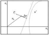
图2示出了根据本发明实施例提供的临界控制余度向量示意图。Fig. 2 shows a schematic diagram of critical control margin vectors provided according to an embodiment of the present invention.
图3示出了根据本发明实施例提供的线性限制边界示意图;Fig. 3 shows a schematic diagram of a linear limit boundary provided according to an embodiment of the present invention;
图4示出了根据本发明实施例提供的控制律结构框图。Fig. 4 shows a structural block diagram of a control law provided according to an embodiment of the present invention.
具体实施方式detailed description
需要说明的是,在不冲突的情况下,本申请中的实施例及实施例中的特征可以相互组合。下面将结合本发明实施例中的附图,对本发明实施例中的技术方案进行清楚、完整地描述,显然,所描述的实施例仅仅是本发明一部分实施例,而不是全部的实施例。以下对至少一个示例性实施例的描述实际上仅仅是说明性的,决不作为对本发明及其应用或使用的任何限制。基于本发明中的实施例,本领域普通技术人员在没有作出创造性劳动前提下所获得的所有其他实施例,都属于本发明保护的范围。It should be noted that, in the case of no conflict, the embodiments in the present application and the features in the embodiments can be combined with each other. The following will clearly and completely describe the technical solutions in the embodiments of the present invention with reference to the accompanying drawings in the embodiments of the present invention. Obviously, the described embodiments are only some, not all, embodiments of the present invention. The following description of at least one exemplary embodiment is merely illustrative in nature and in no way taken as limiting the invention, its application or uses. Based on the embodiments of the present invention, all other embodiments obtained by persons of ordinary skill in the art without creative efforts fall within the protection scope of the present invention.
需要注意的是,这里所使用的术语仅是为了描述具体实施方式,而非意图限制根据本申请的示例性实施方式。如在这里所使用的,除非上下文另外明确指出,否则单数形式也意图包括复数形式,此外,还应当理解的是,当在本说明书中使用术语“包含”和/或“包括”时,其指明存在特征、步骤、操作、器件、组件和/或它们的组合。It should be noted that the terminology used here is only for describing specific implementations, and is not intended to limit the exemplary implementations according to the present application. As used herein, unless the context clearly dictates otherwise, the singular is intended to include the plural, and it should also be understood that when the terms "comprising" and/or "comprising" are used in this specification, they mean There are features, steps, operations, means, components and/or combinations thereof.
除非另外具体说明,否则在这些实施例中阐述的部件和步骤的相对布置、数字表达式和数值不限制本发明的范围。同时,应当明白,为了便于描述,附图中所示出的各个部分的尺寸并不是按照实际的比例关系绘制的。对于相关领域普通技术人员已知的技术、方法和设备可能不作详细讨论,但在适当情况下,所述技术、方法和设备应当被视为授权说明书的一部分。在这里示出和讨论的所有示例中,任何具体值应被解释为仅仅是示例性的,而不是作为限制。因此,示例性实施例的其它示例可以具有不同的值。应注意到:相似的标号和字母在下面的附图中表示类似项,因此,一旦某一项在一个附图中被定义,则在随后的附图中不需要对其进行进一步讨论。The relative arrangements of components and steps, numerical expressions and numerical values set forth in these embodiments do not limit the scope of the present invention unless specifically stated otherwise. At the same time, it should be understood that, for the convenience of description, the sizes of the various parts shown in the drawings are not drawn according to the actual proportional relationship. Techniques, methods and devices known to those of ordinary skill in the relevant art may not be discussed in detail, but where appropriate, such techniques, methods and devices should be considered part of the Authorized Specification. In all examples shown and discussed herein, any specific values should be construed as exemplary only, and not as limitations. Therefore, other examples of the exemplary embodiment may have different values. It should be noted that like numerals and letters denote like items in the following figures, therefore, once an item is defined in one figure, it does not require further discussion in subsequent figures.
如图1所示,根据本发明实施例提供一种无人飞行器飞行包线保护方法,包括以下步骤:As shown in Figure 1, according to an embodiment of the present invention, a method for protecting the flight envelope of an unmanned aerial vehicle is provided, including the following steps:
步骤一,确定无人飞行器的限制参数在动平衡条件下的飞行动力学方程,Step 1, determining the flight dynamics equation of the limiting parameters of the unmanned aerial vehicle under dynamic balance conditions,
在一个实施例中,描述飞行器飞行动力学的非线性状态方程可以写为:In one embodiment, the nonlinear equation of state describing the flight dynamics of an aircraft can be written as:

其中,xs为慢状态量,xf为快状态量,yp为限制参数,u为操纵量,


根据时标分离原则,状态向量被划分为k个慢状态xs和n-k个快状态xf。在本实施例中,慢状态为随时间缓慢变化的飞行参数,如前飞速度、爬升率、欧拉角和高度等,这些参数在机动飞行过程中不会一直保持稳定值。快状态为随时间变化较快的飞行参数,如姿态角速率等,这些参数在正常机动过程中很快达到稳态。输出向量yp表示需要约束在飞行包线内的一组限制参数。According to the time scale separation principle, the state vector is divided into k slow states xs and nk fast states xf . In this embodiment, the slow state refers to flight parameters that change slowly over time, such as forward flight speed, climb rate, Euler angle, altitude, etc. These parameters will not always maintain a stable value during the maneuvering flight. The fast state refers to flight parameters that change rapidly with time, such as attitude rate, etc., and these parameters quickly reach a steady state during normal maneuvering. The output vectoryp represents a set of limiting parameters that need to be constrained within the flight envelope.
在本实施例中,动态平衡被定义为快状态量变化率为零的准稳态机动。假设操纵量u已知,则上述系统可以表示为具有n+k+l个未知数的n+l个方程。可以通过测量k个慢状态量xs的值,以消去k个未知数。并且在动态配平中,隐含限制参数的值与操纵量和被测状态量的函数关系,从而得到公式(2):In this embodiment, dynamic equilibrium is defined as a quasi-steady-state maneuver with a fast state quantity change rate of zero. Assuming that the manipulated variable u is known, the above system can be expressed as n+l equations with n+k+l unknowns. It is possible to eliminate k unknowns by measuring the values of k slow state quantities xs . And in the dynamic trim, the functional relationship between the value of the implicit limit parameter and the manipulated variable and the measured state variable is obtained, so that the formula (2) is obtained:

其中,ff为快状态量、慢状态量与操纵量之间的函数关系,f为动态平衡中慢状态量和操纵量与限制参数之间的关系,该函数具有高度非线性,可用基于实验数据的分析模型或经验模型表示。Among them, ff is the functional relationship between the fast state quantity, the slow state quantity and the manipulated quantity, and f is the relationship between the slow state quantity, the manipulated quantity and the limiting parameter in the dynamic balance. This function is highly nonlinear and can be used based on experiments Analytical model or empirical model representation of data.
由此得到动态平衡条件下的飞行动力学方程:Thus, the flight dynamics equation under dynamic equilibrium conditions is obtained:

步骤二,根据飞行方程确定限制参数在动平衡状态下的临界控制余度向量;Step 2, determining the critical control margin vector of the limiting parameters in the dynamic balance state according to the flight equation;
当一个限制参数受到多个操纵量影响时,其超限会由无穷多个操纵量组合导致。例如,直升机纵向周期变距和总距操纵的不同组合均有可能使迎角达到极限值。为预测控制余度,可以通过将包线限制映射到操纵量的向量空间,然后寻找使限制参数在动态配平中达到包线边界的最短控制向量。最短控制向量被称为临界控制余度向量,每个限制参数对应一个临界控制余度向量。When a limiting parameter is affected by multiple manipulated variables, its overrun will be caused by infinitely many combinations of manipulated variables. For example, different combinations of helicopter longitudinal cyclic pitch change and collective pitch control may make the angle of attack reach the limit value. In order to predict the control margin, the envelope limit can be mapped to the vector space of the manipulated variable, and then the shortest control vector that makes the limit parameter reach the envelope boundary in dynamic trim can be found. The shortest control vector is called a critical control margin vector, and each limiting parameter corresponds to a critical control margin vector.
式(3)将每个限制参数yi,均表示成慢状态xs和操纵量u的函数。对于限制参数有:Equation (3) expresses each limiting parameter yi as a function of the slow state xs and the manipulated variable u. For limit parameters there are:

u*为限制参数所对应的操纵量边界,其中
如图1所示,临界控制余度向量Δu为:As shown in Figure 1, the critical control margin vector Δu is:
Δu=u*-u0 (5)Δu=u* -u0 (5)
上式中u0为当前控制位置。In the above formula, u0 is the current control position.
直接计算式(4)中的非线性限制边界较为困难。在本实施例中,临界控制余度向量可以通过将f中的函数线性化来近似计算。在一个实施例中,对限制参数进行泰勒展开:It is difficult to directly calculate the nonlinear limit boundary in formula (4). In this embodiment, the critical control margin vector can be approximated by linearizing the function in f. In one embodiment, a Taylor expansion is performed on the constraint parameter:

则可以用以下线性化方程近似逼近限制边界:Then the limit boundary can be approximated by the following linearization equation:

用M的Moore-Penrose逆计算到达限制边界的最小控制向量Δu:Use the Moore-Penrose inverse of M to calculate the minimum control vector Δu reaching the limit boundary:

上式中Δu为限制参数在动平衡状态下到达限制边界的控制余量。In the above formula, Δu is the control margin for the limit parameter to reach the limit boundary in the state of dynamic balance.
在其他实施例中,可采用其他线性化方法对公式(4)进行线性化,从而计算限制参数在动平衡状态下到达限制边界的控制余量。In other embodiments, other linearization methods may be used to linearize the formula (4), so as to calculate the control margin for the limit parameter to reach the limit boundary in the state of dynamic balance.
临界控制余度向量采用限制边界线性化近似计算,如图2所示。真实的限制边界是非线性的,因此线性化的模型必须不断实时更新。线性化后的边界并不精确,但随着边界的逼近,它成为一个与真实非线性边界相切的曲面,因此,当飞行器接近极限时,可以认为线性逼近是准确的。The critical control margin vector is approximated by linearizing the limit boundary, as shown in Fig. 2. The real limiting boundaries are nonlinear, so the linearized model must be constantly updated in real time. The linearized boundary is not exact, but as the boundary is approached, it becomes a surface tangent to the true nonlinear boundary, so the linear approximation can be considered accurate as the vehicle approaches the limit.
步骤三,根据临界控制余度确定控制系统的控制律,所述控制律的基本原理为:为系统提供与临界控制余度向量的2范数成反比的负反馈,从而使得当飞行器接近飞行包线时,操纵输入逐渐减小。Step 3, determine the control law of the control system according to the critical control margin, the basic principle of the control law is: provide the system with negative feedback inversely proportional to the 2 norm of the critical control margin vector, so that when the aircraft approaches the flight bag line, the manipulation input gradually decreases.
进一步的在一个实施例中,控制系统的控制律为:Further in one embodiment, the control law of the control system is:

其中向量v为飞行员操纵输入,u为所得到的带限制反馈的操纵量。K为可调比例系数,K值越大,表示控制作用越灵敏。其控制律结构框图如图3所示,该控制回路效果为,当飞行员操纵输入逐渐增加时,输入信号u逐渐接近限制边界,但不会超过限制。Among them, the vector v is the pilot's control input, and u is the obtained control amount with limited feedback. K is an adjustable proportional coefficient, the larger the K value, the more sensitive the control. The structure diagram of its control law is shown in Figure 3. The effect of the control loop is that when the pilot's control input gradually increases, the input signal u gradually approaches the limit boundary, but will not exceed the limit.
如果控制限制边界u*为常数,且可以确定,那么式(9)中的实际操纵量可以用代数方法求解。在一个实施中,在单个控制通道的情况下,控制律近似为:If the control limit boundary u* is constant and can be determined, then the actual manipulated variable in formula (9) can be solved algebraically. In one implementation, in the case of a single control channel, the control law is approximated as:

其中,k为可调比例系数,根据实际情况进行选取。Among them, k is an adjustable proportional coefficient, which is selected according to the actual situation.
一种介质,存储本发明的无人飞行器飞行包线保护方法。A medium stores the flight envelope protection method of an unmanned aerial vehicle of the present invention.
一种飞行器,使用本发明的无人飞行器飞行包线保护方法进行飞行包线保护。An aircraft uses the flight envelope protection method of an unmanned aircraft of the invention to protect the flight envelope.
综上,本发明提供的一种无人飞行器飞行包线保护方法,相比于现有技术至少具有以下优势:In summary, a method for protecting the flight envelope of an unmanned aerial vehicle provided by the present invention has at least the following advantages compared with the prior art:
(1)本发明根据无人飞行器限制参数的动态响应特性和传感器可测的飞行参数,得到了临界控制余度向量,并通过反馈控制实现了限制避免,可使飞行器在整个飞行包线内限制参数均不超过限制边界,有效提升飞行的安全性和可靠性;(1) The present invention obtains the critical control margin vector according to the dynamic response characteristics of the unmanned aircraft's limiting parameters and the measurable flight parameters of the sensor, and realizes the limitation avoidance through feedback control, which can make the aircraft limit in the entire flight envelope. None of the parameters exceed the limit boundary, effectively improving flight safety and reliability;
(2)本发明计算简单、快速,减小了控制延迟,从而满足在无人飞行器实际工程上应用。(2) The calculation of the present invention is simple and fast, and the control delay is reduced, thereby satisfying the practical engineering application of unmanned aerial vehicles.
为了便于描述,在这里可以使用空间相对术语,如“在……之上”、“在……上方”、“在……上表面”、“上面的”等,用来描述如在图中所示的一个器件或特征与其他器件或特征的空间位置关系。应当理解的是,空间相对术语旨在包含除了器件在图中所描述的方位之外的在使用或操作中的不同方位。例如,如果附图中的器件被倒置,则描述为“在其他器件或构造上方”或“在其他器件或构造之上”的器件之后将被定位为“在其他器件或构造下方”或“在其他器件或构造之下”。因而,示例性术语“在……上方”可以包括“在……上方”和“在……下方”两种方位。该器件也可以其他不同方式定位(旋转90度或处于其他方位),并且对这里所使用的空间相对描述作出相应解释。For the convenience of description, spatially relative terms may be used here, such as "on ...", "over ...", "on the surface of ...", "above", etc., to describe the The spatial positional relationship between one device or feature shown and other devices or features. It will be understood that the spatially relative terms are intended to encompass different orientations of the device in use or operation in addition to the orientation depicted in the figures. For example, if the device in the figures is turned over, devices described as "above" or "above" other devices or configurations would then be oriented "beneath" or "above" the other devices or configurations. under other devices or configurations". Thus, the exemplary term "above" can encompass both an orientation of "above" and "beneath". The device may be otherwise oriented (rotated 90 degrees or at other orientations) and the spatially relative descriptions used herein interpreted accordingly.
此外,需要说明的是,使用“第一”、“第二”等词语来限定零部件,仅仅是为了便于对相应零部件进行区别,如没有另行声明,上述词语并没有特殊含义,因此不能理解为对本发明保护范围的限制。In addition, it should be noted that the use of words such as "first" and "second" to define components is only for the convenience of distinguishing corresponding components. To limit the protection scope of the present invention.
以上仅为本发明的优选实施例而已,并不用于限制本发明,对于本领域的技术人员来说,本发明可以有各种更改和变化。凡在本发明的精神和原则之内,所作的任何修改、等同替换、改进等,均应包含在本发明的保护范围之内。The above are only preferred embodiments of the present invention, and are not intended to limit the present invention. For those skilled in the art, the present invention may have various modifications and changes. Any modifications, equivalent replacements, improvements, etc. made within the spirit and principles of the present invention shall be included within the protection scope of the present invention.
Claims (6)


Priority Applications (1)
| Application Number | Priority Date | Filing Date | Title |
|---|---|---|---|
| CN202110737828.5ACN115562318B (en) | 2021-06-30 | 2021-06-30 | A flight envelope protection method for unmanned aerial vehicle |
Applications Claiming Priority (1)
| Application Number | Priority Date | Filing Date | Title |
|---|---|---|---|
| CN202110737828.5ACN115562318B (en) | 2021-06-30 | 2021-06-30 | A flight envelope protection method for unmanned aerial vehicle |
Publications (2)
| Publication Number | Publication Date |
|---|---|
| CN115562318Atrue CN115562318A (en) | 2023-01-03 |
| CN115562318B CN115562318B (en) | 2025-03-18 |
Family
ID=84736941
Family Applications (1)
| Application Number | Title | Priority Date | Filing Date |
|---|---|---|---|
| CN202110737828.5AActiveCN115562318B (en) | 2021-06-30 | 2021-06-30 | A flight envelope protection method for unmanned aerial vehicle |
Country Status (1)
| Country | Link |
|---|---|
| CN (1) | CN115562318B (en) |
Citations (7)
| Publication number | Priority date | Publication date | Assignee | Title |
|---|---|---|---|---|
| US6332105B1 (en)* | 1999-05-21 | 2001-12-18 | Georgia Tech Research Corporation | Neural network based automatic limit prediction and avoidance system and method |
| US20020161489A1 (en)* | 2001-04-27 | 2002-10-31 | Lockheed Martin Corporation | Automatic flight envelope protection for uninhabited air vehicles |
| US20130211634A1 (en)* | 2012-02-14 | 2013-08-15 | Sikorsky Aircraft Corporation | Method and system for providing sideslip envelope protection |
| CN111352437A (en)* | 2018-12-20 | 2020-06-30 | 庞巴迪公司 | Method and system for longitudinal control of an aircraft |
| CN112478137A (en)* | 2019-09-11 | 2021-03-12 | 波音公司 | System and method for pitch axis envelope limiting of an aircraft |
| CN112597593A (en)* | 2020-12-25 | 2021-04-02 | 中国航空工业集团公司沈阳飞机设计研究所 | Airplane boundary limit control law and design method thereof |
| CN112673409A (en)* | 2018-08-27 | 2021-04-16 | 湾流航空航天公司 | Predicted aircraft flight envelope protection system |
- 2021
- 2021-06-30CNCN202110737828.5Apatent/CN115562318B/enactiveActive
Patent Citations (7)
| Publication number | Priority date | Publication date | Assignee | Title |
|---|---|---|---|---|
| US6332105B1 (en)* | 1999-05-21 | 2001-12-18 | Georgia Tech Research Corporation | Neural network based automatic limit prediction and avoidance system and method |
| US20020161489A1 (en)* | 2001-04-27 | 2002-10-31 | Lockheed Martin Corporation | Automatic flight envelope protection for uninhabited air vehicles |
| US20130211634A1 (en)* | 2012-02-14 | 2013-08-15 | Sikorsky Aircraft Corporation | Method and system for providing sideslip envelope protection |
| CN112673409A (en)* | 2018-08-27 | 2021-04-16 | 湾流航空航天公司 | Predicted aircraft flight envelope protection system |
| CN111352437A (en)* | 2018-12-20 | 2020-06-30 | 庞巴迪公司 | Method and system for longitudinal control of an aircraft |
| CN112478137A (en)* | 2019-09-11 | 2021-03-12 | 波音公司 | System and method for pitch axis envelope limiting of an aircraft |
| CN112597593A (en)* | 2020-12-25 | 2021-04-02 | 中国航空工业集团公司沈阳飞机设计研究所 | Airplane boundary limit control law and design method thereof |
Non-Patent Citations (1)
| Title |
|---|
| 张忠佐: "直升机飞行包线保护方法研究", 中国优秀硕士学位论文全文数据库工程科技Ⅱ辑, no. 07, 15 July 2021 (2021-07-15), pages 031 - 69* |
Also Published As
| Publication number | Publication date |
|---|---|
| CN115562318B (en) | 2025-03-18 |
Similar Documents
| Publication | Publication Date | Title |
|---|---|---|
| CN109018421B (en) | System for estimating airspeed of aircraft based on drag model | |
| RU2755843C2 (en) | System and method for estimating airspeed of aircraft based on model of weather data accumulation | |
| US8346408B2 (en) | Fault tolerant flight control system | |
| US8442701B2 (en) | Dynamic roll angle stall protection for an aircraft | |
| US10261518B2 (en) | Method and apparatus for protecting aircraft maximum lift capability | |
| JPH0858697A (en) | Aircraft actively controlled relative to air using airspeed vector measurement device | |
| Brodecki et al. | Autonomous formation flight control system using in-flight sweet-spot estimation | |
| RU2615220C1 (en) | Method of determination of the control signal on the corner of the roll model of the hyperpower vehicle equipment (hve) for monitoring the aerodynamic identity on the reinolds number of trajectories of the flight of the model and the nuclear article when conducting anti-state aircraft research | |
| Bhardwaj et al. | Thrust command based integrated reference model with envelope protections for tilt-rotor vtol transition uav | |
| CN111506099A (en) | Intelligent control system and method for height of unmanned aerial vehicle | |
| CN105527455A (en) | Method and device for automatically estimating at least one speed of an aircraft | |
| Herrmann et al. | Nonlinear system identification of a UAV model with distributed aerodynamics and flexible structure | |
| CN119670505A (en) | A controllability analysis method for deformable UAV | |
| Manai et al. | Identification of a UAV and design of a hardware-in-the-loop system for nonlinear control purposes | |
| CN115562318A (en) | A method for protecting the flight envelope of an unmanned aerial vehicle | |
| Millidere et al. | Further investigations on Newton-Raphson methods in aircraft trim | |
| Brodecki et al. | Formation flight control system for in-flight sweet spot estimation | |
| Hirahara et al. | Influences of aerodynamic parameter uncertainties for UFSC based flight trajectory generation | |
| CN115859461A (en) | Longitudinal controllable domain and stability analysis method for low-speed fixed wing unmanned aerial vehicle | |
| Marton et al. | Hybrid model-based and data-driven wind velocity estimator for an autonomous robotic airship | |
| Jain et al. | A novel methodology to update table in air data system of a high performance fighter aircraft | |
| Lynch et al. | Creating MATLAB simulations to model aircraft dynamics | |
| Burke | Aerodynamic load reduction techniques for large elastic launch vehicles | |
| Krings et al. | A predictive envelope protection system using linear, parameter-varying models | |
| Amankwah | A Three Degrees of Freedom (3DoF) Dynamic Modeling and Simulation of an Unmanned Aerial Vehicles |
Legal Events
| Date | Code | Title | Description |
|---|---|---|---|
| PB01 | Publication | ||
| PB01 | Publication | ||
| SE01 | Entry into force of request for substantive examination | ||
| SE01 | Entry into force of request for substantive examination | ||
| GR01 | Patent grant | ||
| GR01 | Patent grant |