CN115556755A - Vehicle state estimation method and system combining neural network and unscented Kalman filtering - Google Patents
Vehicle state estimation method and system combining neural network and unscented Kalman filteringDownload PDFInfo
- Publication number
- CN115556755A CN115556755ACN202211200764.6ACN202211200764ACN115556755ACN 115556755 ACN115556755 ACN 115556755ACN 202211200764 ACN202211200764 ACN 202211200764ACN 115556755 ACN115556755 ACN 115556755A
- Authority
- CN
- China
- Prior art keywords
- state
- vehicle
- neural network
- automobile
- formula
- Prior art date
- Legal status (The legal status is an assumption and is not a legal conclusion. Google has not performed a legal analysis and makes no representation as to the accuracy of the status listed.)
- Pending
Links
- 238000013528artificial neural networkMethods0.000titleclaimsabstractdescription93
- 238000000034methodMethods0.000titleclaimsabstractdescription40
- 238000001914filtrationMethods0.000titleclaimsabstract7
- 239000011159matrix materialSubstances0.000claimsdescription48
- 238000005259measurementMethods0.000claimsdescription44
- 230000001133accelerationEffects0.000claimsdescription40
- 238000004364calculation methodMethods0.000claimsdescription11
- 230000003993interactionEffects0.000claimsdescription8
- 210000002569neuronAnatomy0.000claimsdescription8
- 230000004927fusionEffects0.000claimsdescription7
- 230000008859changeEffects0.000claimsdescription5
- 230000003287optical effectEffects0.000claimsdescription5
- 238000003062neural network modelMethods0.000claimsdescription4
- 230000008569processEffects0.000claimsdescription3
- 230000009625temporal interactionEffects0.000claimsdescription3
- 230000010354integrationEffects0.000claimsdescription2
- 238000012544monitoring processMethods0.000claimsdescription2
- 210000005036nerveAnatomy0.000claimsdescription2
- 230000008878couplingEffects0.000abstractdescription2
- 238000010168coupling processMethods0.000abstractdescription2
- 238000005859coupling reactionMethods0.000abstractdescription2
- 230000006870functionEffects0.000description16
- 238000012360testing methodMethods0.000description6
- 238000011161developmentMethods0.000description4
- 238000002474experimental methodMethods0.000description4
- 238000005516engineering processMethods0.000description3
- 238000004088simulationMethods0.000description3
- 238000012549trainingMethods0.000description3
- 238000013459approachMethods0.000description2
- 230000008901benefitEffects0.000description2
- 238000013461designMethods0.000description2
- 230000000694effectsEffects0.000description2
- 238000005096rolling processMethods0.000description2
- 230000007704transitionEffects0.000description2
- 241000567769Isurus oxyrinchusSpecies0.000description1
- SAZUGELZHZOXHB-UHFFFAOYSA-NacecarbromalChemical compoundCCC(Br)(CC)C(=O)NC(=O)NC(C)=OSAZUGELZHZOXHB-UHFFFAOYSA-N0.000description1
- 230000004913activationEffects0.000description1
- 230000009286beneficial effectEffects0.000description1
- 239000004568cementSubstances0.000description1
- 238000004891communicationMethods0.000description1
- 230000000052comparative effectEffects0.000description1
- 230000001186cumulative effectEffects0.000description1
- 230000001419dependent effectEffects0.000description1
- 230000006872improvementEffects0.000description1
- 238000013507mappingMethods0.000description1
- 238000005295random walkMethods0.000description1
- 230000009467reductionEffects0.000description1
- 230000010076replicationEffects0.000description1
- 238000011160researchMethods0.000description1
- 238000005070samplingMethods0.000description1
- 230000002123temporal effectEffects0.000description1
- 238000010200validation analysisMethods0.000description1
Images


Classifications
- B—PERFORMING OPERATIONS; TRANSPORTING
- B60—VEHICLES IN GENERAL
- B60W—CONJOINT CONTROL OF VEHICLE SUB-UNITS OF DIFFERENT TYPE OR DIFFERENT FUNCTION; CONTROL SYSTEMS SPECIALLY ADAPTED FOR HYBRID VEHICLES; ROAD VEHICLE DRIVE CONTROL SYSTEMS FOR PURPOSES NOT RELATED TO THE CONTROL OF A PARTICULAR SUB-UNIT
- B60W40/00—Estimation or calculation of non-directly measurable driving parameters for road vehicle drive control systems not related to the control of a particular sub unit, e.g. by using mathematical models
- B60W40/10—Estimation or calculation of non-directly measurable driving parameters for road vehicle drive control systems not related to the control of a particular sub unit, e.g. by using mathematical models related to vehicle motion
- B60W40/105—Speed
- B—PERFORMING OPERATIONS; TRANSPORTING
- B60—VEHICLES IN GENERAL
- B60W—CONJOINT CONTROL OF VEHICLE SUB-UNITS OF DIFFERENT TYPE OR DIFFERENT FUNCTION; CONTROL SYSTEMS SPECIALLY ADAPTED FOR HYBRID VEHICLES; ROAD VEHICLE DRIVE CONTROL SYSTEMS FOR PURPOSES NOT RELATED TO THE CONTROL OF A PARTICULAR SUB-UNIT
- B60W2510/00—Input parameters relating to a particular sub-units
- B60W2510/20—Steering systems
- B60W2510/202—Steering torque
- B—PERFORMING OPERATIONS; TRANSPORTING
- B60—VEHICLES IN GENERAL
- B60W—CONJOINT CONTROL OF VEHICLE SUB-UNITS OF DIFFERENT TYPE OR DIFFERENT FUNCTION; CONTROL SYSTEMS SPECIALLY ADAPTED FOR HYBRID VEHICLES; ROAD VEHICLE DRIVE CONTROL SYSTEMS FOR PURPOSES NOT RELATED TO THE CONTROL OF A PARTICULAR SUB-UNIT
- B60W2520/00—Input parameters relating to overall vehicle dynamics
- B60W2520/10—Longitudinal speed
- B60W2520/105—Longitudinal acceleration
- B—PERFORMING OPERATIONS; TRANSPORTING
- B60—VEHICLES IN GENERAL
- B60W—CONJOINT CONTROL OF VEHICLE SUB-UNITS OF DIFFERENT TYPE OR DIFFERENT FUNCTION; CONTROL SYSTEMS SPECIALLY ADAPTED FOR HYBRID VEHICLES; ROAD VEHICLE DRIVE CONTROL SYSTEMS FOR PURPOSES NOT RELATED TO THE CONTROL OF A PARTICULAR SUB-UNIT
- B60W2520/00—Input parameters relating to overall vehicle dynamics
- B60W2520/12—Lateral speed
- B60W2520/125—Lateral acceleration
- B—PERFORMING OPERATIONS; TRANSPORTING
- B60—VEHICLES IN GENERAL
- B60W—CONJOINT CONTROL OF VEHICLE SUB-UNITS OF DIFFERENT TYPE OR DIFFERENT FUNCTION; CONTROL SYSTEMS SPECIALLY ADAPTED FOR HYBRID VEHICLES; ROAD VEHICLE DRIVE CONTROL SYSTEMS FOR PURPOSES NOT RELATED TO THE CONTROL OF A PARTICULAR SUB-UNIT
- B60W2540/00—Input parameters relating to occupants
- B60W2540/18—Steering angle
Landscapes
- Engineering & Computer Science (AREA)
- Physics & Mathematics (AREA)
- Automation & Control Theory (AREA)
- Mathematical Physics (AREA)
- Transportation (AREA)
- Mechanical Engineering (AREA)
- Navigation (AREA)
Abstract
Description
Translated fromChinese技术领域technical field
本发明属于车辆智能驾驶领域,特别是涉及一种结合神经网络与无迹卡尔曼滤波的车辆状态估计方法及系统。The invention belongs to the field of vehicle intelligent driving, and in particular relates to a vehicle state estimation method and system combining a neural network and an unscented Kalman filter.
背景技术Background technique
随着智能交通系统的发展与嵌入式系统成本的降低,原始设备制造商不断提供新的电子控制系统以实现更安全、更智能的汽车。多个子控制系统涵盖更多复杂的汽车碰撞情况,也更依赖于准确的车辆状态。随着传感器技术的发展,例如GNSS、IMU、方向盘传感器等已应用于汽车控制系统,这些传感器能提供更精确也更丰富的汽车状态信息。而传感器噪声会影响车辆状态的准确性、可靠性或连续性,车辆状态估计方法能降低传感器噪声并且推断出难以测量的车辆状态,如侧滑角等。基于车辆模型的状态估计方法适用于大多数道路。但是摩擦力等一些特性很难明确建模,因此对非线性、极限的汽车状态预测结果较差。虽然数据驱动的状态估计方法具有更高的仿真能力,在无人驾驶汽车模拟中也取得了极大成功。但数据驱动的方法是一个“黑箱”模型,缺乏对其推理背后逻辑的理解,其结果可能与人类的判断不一致。此外,无迹卡尔曼滤波器(UKF)是基于车辆模型的状态估计方法的经典理论,融合了不同的车辆/轮胎模型和实时状态,以处理干扰和噪声。考虑到这两种状态估计方法的缺点,本文提出了一种结合神经网络与无迹卡尔曼滤波的车辆状态估计方法。With the development of intelligent transportation systems and the reduction of the cost of embedded systems, original equipment manufacturers continue to provide new electronic control systems to realize safer and smarter vehicles. Multiple sub-control systems cover more complex car crash situations and are more dependent on accurate vehicle state. With the development of sensor technology, such as GNSS, IMU, steering wheel sensors, etc., have been applied to vehicle control systems, and these sensors can provide more accurate and richer vehicle status information. While sensor noise can affect the accuracy, reliability, or continuity of the vehicle state, vehicle state estimation methods can reduce sensor noise and infer vehicle states that are difficult to measure, such as sideslip angle. State estimation methods based on vehicle models are suitable for most roads. But some properties, such as friction, are difficult to model explicitly, and thus predict poorly for non-linear, extreme car states. Although data-driven state estimation methods have higher simulation capabilities, they have also achieved great success in autonomous vehicle simulations. But the data-driven approach is a "black box" model that lacks an understanding of the logic behind its reasoning, and its results may not align with human judgment. Furthermore, the Unscented Kalman Filter (UKF) is a classic theory of vehicle model-based state estimation methods, which fuse different vehicle/tire models and real-time states to deal with disturbances and noises. Considering the shortcomings of these two state estimation methods, this paper proposes a vehicle state estimation method combining neural network and unscented Kalman filter.
发明内容Contents of the invention
本发明公开了一种结合神经网络与无迹卡尔曼滤波的车辆状态估计方法。该方法利用汽车多传感器中获得的数据,建立神经网络精确估计三向加速度与三向角速度。该状态可以定义汽车底盘的运动以实现协调各子系统所需要的汽车状态。结合神经网络的无迹卡尔曼滤波可以更好的估计汽车的3D姿态、速度、定位,估计出的状态可以应用于汽车的主动安全系统、操纵稳定性系统等。The invention discloses a vehicle state estimation method combining neural network and unscented Kalman filter. The method utilizes the data obtained from the automobile's multi-sensors to establish a neural network to accurately estimate the three-way acceleration and three-way angular velocity. This state can define the movement of the car chassis to achieve the car state required to coordinate the various subsystems. The unscented Kalman filter combined with the neural network can better estimate the 3D attitude, speed, and positioning of the car, and the estimated state can be applied to the active safety system and handling stability system of the car.
本发明采用的技术方案如下:The technical scheme that the present invention adopts is as follows:
一种结合神经网络与无迹卡尔曼滤波的车辆状态估计方法,包括以下步骤:A vehicle state estimation method combining neural network and unscented Kalman filter, comprising the following steps:
S1,多传感器测量汽车实时状态;S1, multi-sensors measure the real-time status of the car;
S2,神经网络求得汽车状态估计值;S2, the neural network obtains the estimated value of the vehicle state;
S3,无迹卡尔曼滤波建模仿真汽车运动规律并估计汽车状态。S3, unscented Kalman filter modeling and simulating the law of car movement and estimating the state of the car.
所述步骤S1多传感器测量汽车实时状态,包括:The multi-sensor measurement of the step S1 real-time state of the car, including:
A1,光学测量,捕捉纵向速度与加速度、横向速度与加速度和三轴角速度(横滚角速度、俯仰角速度、横摆角速度);A1, optical measurement, capturing longitudinal velocity and acceleration, lateral velocity and acceleration, and three-axis angular velocity (rolling angular velocity, pitching angular velocity, yaw angular velocity);
A2,方向盘传感器,捕捉方向盘转角、转速、转矩;A2, the steering wheel sensor, captures the steering wheel angle, speed, and torque;
A3,全球导航卫星系统,捕捉定位;A3, global navigation satellite system, capturing and positioning;
A4,IMU惯性测量单元,用于测量物体三轴姿态角(或角速率)以及加速度。A4, IMU inertial measurement unit, used to measure the three-axis attitude angle (or angular rate) and acceleration of the object.
A5,车轮六分力测量系统,用于测量轮胎六分力;A5, wheel six-component force measurement system, used to measure tire six-component force;
A6,单目相机,捕捉行驶画面。A6, a monocular camera, captures driving images.
所述步骤S2模型包括:The step S2 model includes:
B1,嵌入层,根据历史传感器信息获取目标车辆的隐藏状态;B1, the embedding layer, obtains the hidden state of the target vehicle according to the historical sensor information;
B2,时间交互层,连接隐藏状态的时间维度并通过前馈神经网络预测出未来目标车辆的隐藏状态;B2, the time interaction layer, connects the time dimension of the hidden state and predicts the hidden state of the future target vehicle through the feedforward neural network;
B3.1,解码层方案1,根据车辆状态之间的物理学关系,将神经网络输出转换为其他车辆状态,如根据积分将加速度转换为速度;B3.1,
B3.2,解码层方案2,神经网络模型直接输出所需要的汽车状态,如直接输出汽车加速度;B3.2,
B4,根据预测状态与真实状态的误差计算出损失,采取梯度下降的方式调整模型的参数;B4. Calculate the loss according to the error between the predicted state and the real state, and adjust the parameters of the model by gradient descent;
所述步骤S3仿真包括:The step S3 simulation includes:
C1.建立汽车六自由度运动学模型,分为导航坐标和车身坐标。C1. Establish a six-degree-of-freedom kinematics model of the car, which is divided into navigation coordinates and body coordinates.
C2.根据坐标系建立UKF模型,给定初始状态、sigma点、协方差矩阵、状态转移函数、测量函数来跟踪汽车姿态、速度、定位。C2. Establish the UKF model according to the coordinate system, given the initial state, sigma point, covariance matrix, state transition function, and measurement function to track the vehicle's attitude, speed, and positioning.
所述B1嵌入层将传感器数据由全连接层映射到高维,公式为:The B1 embedding layer maps the sensor data from the fully connected layer to high-dimensional, and the formula is:
et=MLPi(xt,Wemb)et =MLPi (xt ,Wemb )
其中e是嵌入的特征向量,t是时间戳,MLP代表多层感知机,i代表预测的汽车状态序号,Wemb是指嵌入层多层感知机的神经元。Where e is the embedded feature vector, t is the timestamp, MLP stands for multi-layer perceptron, i stands for the predicted car state number, Wemb refers to the neurons of the embedding layer multi-layer perceptron.
所述B2时间交互层学习过去所有状态对汽车线性时不变状态的影响,公式为:The B2 time interaction layer learns the influence of all past states on the linear time-invariant state of the car, and the formula is:
eall=Concat(et),t∈[n-L,n]eall =Concat(et ),t∈[nL,n]
e=MLPi(eall,Wtime)e=MLPi (eall ,Wtime )
其中Concat用于连接et中的时间维度,[n-L,n]是过去时间戳长度,e是预测出的汽车的隐状态,eall是连接了时间维度的隐状态,Wtime是时间交互多层感知机的神经元。Among them, Concat is used to connect the time dimension in et , [nL,n] is the length of the past time stamp, e is the hidden state of the predicted car, eall is the hidden state connected to the time dimension, Wtime is the time interaction The neurons of a layer perceptron.
所述B3.1预测传感器误差并估计汽车状态,其公式为:The B3.1 predicts the sensor error and estimates the vehicle state, its formula is:

其中S是预测的汽车状态,
通过相同状态预测的神经网络无法求出误差大小,需用相关状态(例如速度加速度)来进行损失计算,公式为:The neural network predicted by the same state cannot calculate the error size, and the related state (such as velocity acceleration) is needed to calculate the loss. The formula is:

其中Y是相关状态,
所述B3.2预测汽车状态,其公式为:The formula of B3.2 predicting the state of the vehicle is:
S=MLPi(e,Wdecoder)S=MLPi (e, Wdecoder )
Y=Repeat(S,time1→F)Y=Repeat(S,time1→F )
其中Repeat代表将预测状态S根据时间维度复制,F代表预测状态的时间范围。Among them, Repeat represents the replication of the predicted state S according to the time dimension, and F represents the time range of the predicted state.
所述B4损失计算采用MSELOSS,公式为:
所述C1建立汽车六自由度运动学模型。其中导航坐标方向分别为东、北、上,原点是汽车起点。车身坐标x轴朝向车身前方,绕x轴为横滚角的横摇速率ωx,具有纵向速度vx;y轴朝向车身左方,绕y轴为俯仰角的俯仰速率ωy,具有横向速度vy;z轴朝向车身上方,绕z轴为偏航角的横摆速率ωy,具有天向速度vz;The C1 establishes a car six-degree-of-freedom kinematics model. The directions of the navigation coordinates are east, north and up respectively, and the origin is the starting point of the car. The x-axis of the car body coordinates towards the front of the car body, and the roll rate ωx around thex -axis is the roll angle, which has a longitudinal velocity vx ; vy ; the z-axis faces the top of the vehicle body, the yaw rate ωy around the z-axis is the yaw angle, and has a vertical velocity vz ;
所述C2采用流形上的无迹卡尔曼(UKFM)滤波建立车辆IMU-GNSS模型,包括以下步骤:The C2 adopts the Unscented Kalman (UKFM) filter on the manifold to establish the vehicle IMU-GNSS model, including the following steps:
C 2.1,确定先验公式C 2.1, Determining the a priori formula

其中X是汽车状态,

C 2.2,确定IMU-GNSS融合模型中汽车状态X,公式为C 2.2, determine the vehicle state X in the IMU-GNSS fusion model, the formula is
x∈M={C∈SO(3),v∈R3,P∈R3,bg∈R3,ba∈R3}x∈M={C∈SO(3),v∈R3 ,P∈R3 ,bg ∈R3 ,ba ∈R3 }
其中,bg=(ωx,ωy,ωz),ba=(Ax,Ay,Az)是车身坐标下的三向角速度与三向加速度。C是车辆3d旋转矩阵由bg计算得到,v是速度矢量由ba计算得到,p是位置向量根据汽车定位计算。Wherein, bg =(ωx ,ωy ,ωz ), ba =(Ax ,Ay ,Az ) are the three-way angular velocity and three-way acceleration in the body coordinates. C is the vehicle 3d rotation matrix calculated by bg , v is the velocity vector calculated by ba , p is the position vector calculated according to the vehicle positioning.
C 2.3,汽车状态服从先验概率p(X),测量值与先验概率关系为:C 2.3, the state of the car obeys the prior probability p(X), and the relationship between the measured value and the prior probability is:
y=h(X)+∈y=h(X)+∈
其中,h是观测函数,∈是高斯白噪声。根据测量值与先验概率的关系计算近似后验分布P(X|y)。where h is the observation function and ∈ is Gaussian white noise. Computes an approximate posterior distribution P(X|y) from the relationship of the measured values to the prior probability.
C 2.4,使用结合神经网络预测的S替代测量值y。考虑到S是线性时不变的状态,而UKFM需要在每个时刻都进行迭代,根据时间维度扩展预测状态,公式为:C 2.4, using S in conjunction with neural network predictions instead of the measured value y. Considering that S is a linear time-invariant state, and UKFM needs to iterate at each moment, and expand the predicted state according to the time dimension, the formula is:
R′=Repeat(S,time1→F)R'=Repeat(S,time1→F )
R’与观测值y是相同的物理量,观测函数与先验概率保持不变,使用相同的方法计算后验概率P(X|R′)。R' and the observed value y are the same physical quantity, the observation function and the prior probability remain unchanged, and the posterior probability P(X|R') is calculated using the same method.
所述C2.4计算后验概率,包括以下步骤:The C2.4 calculates the posterior probability, comprising the following steps:
C 2.4.1输入平均估计
C 2.4.2设置sigma点C 2.4.2 Setting the sigma point


其中λ是比例参数,εj代表YKF中的样本,具体有2d个样本。where λ is a scale parameter, εj represents the samples in YKF, specifically there are 2d samples.
C 2.4.3结合测量函数,与设置的sigma点进行无迹卡尔曼变化C 2.4.3 Unscented Kalman change with the set sigma point in combination with the measurement function


C 2.4.4推断协方差矩阵C 2.4.4 Inferring the covariance matrix

其中,

其中,Pyy是测量协方差矩阵where Pyy is the measurement covariance matrix

其中,Pεy是交叉协方差矩阵where Pεy is the cross-covariance matrix
C 2.4.5更新状态和方差矩阵C 2.4.5 Updating the state and variance matrix

K是滤波增益矩阵K is the filter gain matrix


P+=P-KPyyKTP+ =P-KPyy KT
P+是汽车后验汽协方差矩阵P+ is the auto posterior covariance matrix
C 2.4.6根据推断出的估计值与协方差矩阵,将后验概率p(x|y)转换为估计,公式为:C 2.4.6 According to the inferred estimated value and covariance matrix, convert the posterior probability p(x|y) into an estimate, the formula is:

其中,X是下次输入的平均估计,

基于上述方法,本发明还提出了一种结合神经网络与无迹卡尔曼滤波的车辆状态估计系统,包括:传感器模块、神经网络模块、UKF模块;所述传感器模块配备了监测车辆和道路环境的传感器,获取多种参数,用于研究车辆各传感器结合神经网络的状态估计结果;所述神经网络学习多传感器数据之间潜在的关系,通过线性时不变的方法将学习到的结果应用于UKF模块中,将经过神经网络的映射后的汽车状态与UKF模块结合,估计汽车的3D方向、速度、定位;Based on the above method, the present invention also proposes a vehicle state estimation system combining neural network and unscented Kalman filter, comprising: a sensor module, a neural network module, a UKF module; the sensor module is equipped with a monitoring vehicle and road environment Sensors, which acquire a variety of parameters, are used to study the state estimation results of each sensor of the vehicle combined with the neural network; the neural network learns the potential relationship between multi-sensor data, and applies the learned results to the UKF through a linear time-invariant method. In the module, the vehicle state mapped by the neural network is combined with the UKF module to estimate the 3D direction, speed, and positioning of the vehicle;
所述传感器模块包括:The sensor module includes:
A1,光学测量部分,捕捉纵向速度与加速度、横向速度与加速度和三轴角速度(横滚角速度、俯仰角速度、横摆角速度);A1, the optical measurement part, captures longitudinal velocity and acceleration, lateral velocity and acceleration, and three-axis angular velocity (rolling angular velocity, pitching angular velocity, yaw angular velocity);
A2,方向盘传感器,捕捉方向盘转角、转速、转矩;A2, the steering wheel sensor, captures the steering wheel angle, speed, and torque;
A3,全球导航卫星系统,捕捉定位;A3, global navigation satellite system, capturing and positioning;
A4,IMU惯性测量单元,用于测量物体三轴姿态角(或角速率)以及加速度;A4, IMU inertial measurement unit, used to measure the three-axis attitude angle (or angular rate) and acceleration of the object;
A5,车轮六分力测量系统,用于测量轮胎六分力;A5, wheel six-component force measurement system, used to measure tire six-component force;
A6,单目相机,捕捉行驶画面;A6, monocular camera, capturing driving images;
所述神经网络模块包括:The neural network module includes:
嵌入层,根据历史传感器信息获取目标车辆的隐藏状态;该层将传感器数据由全连接层映射到高维,公式为:The embedding layer obtains the hidden state of the target vehicle according to the historical sensor information; this layer maps the sensor data from the fully connected layer to high-dimensional, and the formula is:
et=MLPi(xt,Wemb)et =MLPi (xt ,Wemb )
其中e是嵌入的特征向量,t是时间戳,MLP代表多层感知机,具有32个隐藏单元,i代表预测的汽车状态序号,Wemb是嵌入层多层感知机的神经元。;Where e is the embedded feature vector, t is the timestamp, MLP stands for multi-layer perceptron with 32 hidden units, i stands for the predicted car state number, Wemb is the neuron of the embedding layer multi-layer perceptron. ;
时间交互层,连接隐藏状态的时间维度并通过前馈神经网络预测出未来目标车辆的隐藏状态;该层学习过去所有状态对汽车线性时不变状态的影响,公式为:The time interaction layer connects the time dimension of the hidden state and predicts the hidden state of the future target vehicle through the feed-forward neural network; this layer learns the influence of all past states on the linear time-invariant state of the car, and the formula is:
eall=Concat(et),t∈[n-L,n]eall =Concat(et ),t∈[nL,n]
e=MLPi(eall,Wtime)e=MLPi (eall ,Wtime )
其中Concat用于连接et中的时间维度,[n-L,n]是过去时间戳长度,e是预测出的汽车的隐状态;Among them, Concat is used to connect the time dimension in et , [nL,n] is the length of the past timestamp, and e is the hidden state of the predicted car;
解码层,采用方案一,模型预测目标车辆的传感器误差,结合在当前传感器测量到的数值进行汽车行驶状态估计;公式为:The decoding layer adopts

其中S是预测的汽车状态,

其中Y′是相关状态,
或者采用方案二,模型直接预测出所需要的汽车状态,其公式为:Or use the second option, the model directly predicts the required vehicle state, the formula is:
S=MLPi(e,Wdecoder)S=MLPi (e, Wdecoder )
Y=Repeat(S,time1→F)Y=Repeat(S,time1→F )
其中Repeat代表将预测状态S根据时间维度复制,F代表预测状态的时间范围;Among them, Repeat means to copy the predicted state S according to the time dimension, and F represents the time range of the predicted state;
所述神经网络模块采取梯度下降的方式调整模型的参数,损失计算采用MSELOSS,公式为:
所述UKF模块包括:汽车六自由度运动学模型,分为导航坐标和车身坐标,其中导航坐标方向分别为东、北、上,原点是汽车起点;车身坐标x轴朝向车身前方,绕x轴为横滚角的横摇速率ωx,具有纵向速度vx;y轴朝向车身左方,绕y轴为俯仰角的俯仰速率ωy,具有横向速度vy;z轴朝向车身上方,绕z轴为偏航角的横摆速率ωy,具有天向速度vz;The UKF module includes: a car six-degree-of-freedom kinematics model, which is divided into navigation coordinates and body coordinates, wherein the directions of the navigation coordinates are east, north, and up, respectively, and the origin is the starting point of the car; The roll rate ωx is the roll angle, with a longitudinal velocity vx ; the y-axis faces to the left of the vehicle body, and the pitch rate ωy around the y-axis is the pitch angle, which has a lateral velocity vy ; the z-axis faces the top of the vehicle body, and the yaw rate ωy with axis yaw angle, with azimuth velocity vz ;
以及UKF模型,采用流形上的无迹卡尔曼(UKFM)滤波建立的车辆IMU-GNSS模型:给定初始状态、sigma点、协方差矩阵、状态转移函数、测量函数来跟踪汽车姿态、速度、定位;具体建模过程如下And the UKF model, the vehicle IMU-GNSS model established by the unscented Kalman (UKFM) filter on the manifold: given the initial state, sigma point, covariance matrix, state transition function, measurement function to track the vehicle attitude, speed, Positioning; the specific modeling process is as follows
S3.2.1,确定先验公式S3.2.1, Determining the prior formula

其中X是汽车状态,

S3.2.2,确定IMU-GNSS融合模型中汽车状态X,公式为S3.2.2, determine the vehicle state X in the IMU-GNSS fusion model, the formula is
x∈M={C∈SO(3),v∈R3,P∈R3,bg∈R3,ba∈R3}x∈M={C∈SO(3),v∈R3 ,P∈R3 ,bg ∈R3 ,ba ∈R3 }
其中,bg=(ωx,ωy,ωz),ba=(Ax,Ay,Az)是车身坐标下的三向角速度与三向加速度;C是车辆3d旋转矩阵由bg计算得到,v是速度矢量由ba计算得到,p是位置向量根据汽车定位计算;Among them, bg =(ωx ,ωy ,ωz ), ba =(Ax ,Ay ,Az ) are the three-way angular velocity and three-way acceleration in the body coordinates; C is the vehicle 3d rotation matrix composed of bg is calculated, v is the velocity vector calculated by ba , p is the position vector calculated according to the vehicle positioning;
S3.2.3,汽车状态服从先验概率p(X),测量值与先验概率关系为:S3.2.3, the state of the car obeys the prior probability p(X), and the relationship between the measured value and the prior probability is:
y=h(X)+∈y=h(X)+∈
其中,h是观测函数,∈是高斯白噪声,根据测量值与先验概率的关系计算近似后验分布P(X|y);Among them, h is the observation function, ∈ is Gaussian white noise, and the approximate posterior distribution P(X|y) is calculated according to the relationship between the measured value and the prior probability;
S3.2.4,使用结合神经网络预测的S替代测量值y,考虑到S是线性时不变的状态,而UKFM需要在每个时刻都进行迭代,根据时间维度扩展预测状态,公式为:S3.2.4, using S combined with neural network prediction to replace the measured value y, considering that S is a linear time-invariant state, and UKFM needs to iterate at each moment, and expand the predicted state according to the time dimension, the formula is:
R′=Repeat(S,time1→F)R'=Repeat(S,time1→F )
R’与观测值y是相同的物理量,观测函数与先验概率保持不变,使用相同的方法计算后验概率P(X|R′);R' and the observed value y are the same physical quantity, the observation function and the prior probability remain unchanged, and the posterior probability P(X|R') is calculated using the same method;
计算后验概率,包括以下步骤:Calculate the posterior probability, including the following steps:
S3.2.4.1输入平均估计
S3.2.4.2设置sigma点S3.2.4.2 Set sigma point


其中λ是比例参数,εj代表YKF中的样本,具体有2d个样本;Among them, λ is a proportional parameter, εj represents the samples in YKF, specifically there are 2d samples;
S3.2.4.3结合测量函数,与设置的sigma点进行无迹卡尔曼变化S3.2.4.3 Unscented Kalman change with the set sigma point in combination with the measurement function


S3.2.4.4推断协方差矩阵S3.2.4.4 Inferring the covariance matrix

其中,

其中,Pyy是测量协方差矩阵where Pyy is the measurement covariance matrix

其中,Pεy是交叉协方差矩阵where Pεy is the cross-covariance matrix
S3.2.4.5更新状态和方差矩阵S3.2.4.5 Update state and variance matrix

K是滤波增益矩阵K is the filter gain matrix


P+=P-KPyyKTP+ =P-KPyy KT
P+是汽车后验汽协方差矩阵P+ is the auto posterior covariance matrix
S3.2.4.6根据推断出的估计值与协方差矩阵,将后验概率p(x|y)转换为估计,公式为:S3.2.4.6 Convert the posterior probability p(x|y) into an estimate according to the inferred estimated value and covariance matrix, the formula is:

其中,X是下次输入的平均估计,

本发明的有益效果:Beneficial effects of the present invention:
本发明提出的方法提供准确、全面的车辆动态信息。防止车辆各部件之间的信号交换导致的强耦合,从而影响单个状态估计结果的准确性。采取分状态预测的神经网络准确估计汽车状态,相较于过去的神经网络状态估计器,该方案更易训练,更准确。基于神经网络的输出,UKF能更好的估计出汽车3D姿态、速度、定位。当GPS信号不可用时,本方法能提供高度准确的导航信息。The method proposed by the invention provides accurate and comprehensive vehicle dynamic information. Prevent strong coupling caused by signal exchange between various components of the vehicle, which affects the accuracy of individual state estimation results. The neural network that adopts state-by-state prediction accurately estimates the state of the car. Compared with the previous neural network state estimator, this scheme is easier to train and more accurate. Based on the output of the neural network, UKF can better estimate the 3D attitude, speed, and positioning of the car. The method can provide highly accurate navigation information when GPS signals are not available.
附图说明Description of drawings
图1为本发明模型总体架构;Fig. 1 is the overall structure of the model of the present invention;
图2为本发明神经网络模型;Fig. 2 is neural network model of the present invention;
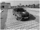
图3为本发明实车硬件配置;Fig. 3 is the real vehicle hardware configuration of the present invention;
图4为实车实验平台Figure 4 is the real vehicle test platform
图5为本发明实验行驶轨迹;Fig. 5 is the experimental driving track of the present invention;
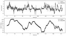
图6为实车数据下纵向加速度与速度对比;Figure 6 shows the comparison of longitudinal acceleration and velocity under real vehicle data;
图7为建模轨迹对比;Figure 7 is a comparison of modeling trajectories;
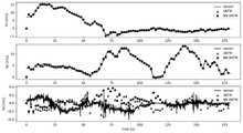
图8为建模三向速度与测量值对比;Fig. 8 is the comparison between the modeling three-way velocity and the measured value;
具体实施方式detailed description
下面将结合本发明实施例中的附图,对本发明实施例中的技术方案进行清楚、完整地描述,显然,所描述的实施例仅仅是本发明一部分实施例,而不是全部的实施例。基于本发明中的实施例,本领域普通技术人员在没有做出创造性劳动前提下所获得的所有其他实施例,都属于本发明保护的范围。The following will clearly and completely describe the technical solutions in the embodiments of the present invention with reference to the accompanying drawings in the embodiments of the present invention. Obviously, the described embodiments are only some of the embodiments of the present invention, not all of them. Based on the embodiments of the present invention, all other embodiments obtained by persons of ordinary skill in the art without making creative efforts belong to the protection scope of the present invention.
如图1所示,本发明系统架构由传感器模块、神经网络模块、UKF模块组成。传感器模块配备了监测车辆和道路环境的传感器,旨在研究车辆各传感器结合神经网络的状态估计结果。神经网络学习多传感器数据之间潜在的关系,通过线性时不变的方法将学习到的结果应用于UKF中。将经过神经网络的映射后的汽车状态与UKF结合,估计汽车的3D方向,速度。定位。考虑到传感器价格与计算速度,传感器模块中放弃了相机与车轮六分力。神经网络模块通过对比研究最后采用前馈神经网络保证速度与精度。UKF模块采用流形上的无迹卡尔曼(UKFM),优点在于多功能性适用于许多状态估计问题。As shown in Figure 1, the system architecture of the present invention consists of a sensor module, a neural network module, and a UKF module. The sensor module is equipped with sensors that monitor the vehicle and road environment, and is designed to study the state estimation results of each sensor of the vehicle combined with the neural network. The neural network learns the potential relationship between multi-sensor data, and applies the learned results to UKF through a linear time-invariant method. Combine the mapped car state with the neural network and UKF to estimate the 3D direction and speed of the car. position. Considering the price of the sensor and the calculation speed, the six-component force of the camera and the wheel is abandoned in the sensor module. The neural network module adopts the feed-forward neural network to ensure the speed and accuracy through comparative research. The UKF module employs Unscented Kalman (UKFM) on manifolds, which has the advantage of versatility for many state estimation problems.
如图2所示,在本发明中,假设神经网络预测出的汽车状态满足线性时不变状态空间模型,来降低与汽车控制结合的难度。不同传感器误差不同,为降低传感器误差对神经网络训练造成的影响,神经网络预测单一状态。为了在复杂非线性的汽车关系中实现精确的状态估计,必须捕捉车辆状态之间复杂的时间关系与交互影响。因此,将神经网络分为三层,嵌入层、时间交互层、Decoder层。As shown in Fig. 2, in the present invention, it is assumed that the vehicle state predicted by the neural network satisfies the linear time-invariant state-space model to reduce the difficulty of combining with vehicle control. Different sensors have different errors. In order to reduce the impact of sensor errors on neural network training, the neural network predicts a single state. In order to achieve accurate state estimation in complex nonlinear vehicle relationships, it is necessary to capture the complex temporal relationships and interaction effects between vehicle states. Therefore, the neural network is divided into three layers, the embedding layer, the time interaction layer, and the Decoder layer.
Encoder层:用于嵌入与编码所有传感器输出的汽车状态,由全连接层映射到高维,MLP具有32个隐藏单元。Encoder layer: used to embed and encode the car state output by all sensors, mapped to high-dimensional by the fully connected layer, MLP has 32 hidden units.
et=MLPi(Xt,Wemb)et =MLPi (Xt ,Wemb )
公式中,MLPi代表预测对应预测状态使用的MLP。et是嵌入的特征向量,Wemb是数线性单元(ELU)激活功能。In the formula, MLPi represents the MLP used by the prediction corresponding to the prediction state. et is the embedding feature vector, Wemb is the linear unit (ELU) activation function.
时间交互层:学习过去所有状态对汽车线性时不变状态的影响。首先,连接et中的时间维度。Temporal Interaction Layer: Learns the effect of all past states on the linear time-invariant state of the car. First, concatenate the time dimension in et .
eall=Concat(et),eall =Concat(et ),
公式中,Concat连接所有过去的隐藏状态,再经过32个隐藏单元的全连接层,学习车辆状态的时间交互影响。In the formula, Concat connects all past hidden states, and then goes through a fully connected layer of 32 hidden units to learn the temporal interaction of vehicle states.
e=MLPi(eall,Wtime)e=MLPi (eall ,Wtime )
解码层:神经网络可用于减少状态中的噪声,或用于预测测量昂贵的汽车状态。因此,预测状态有以下两种计算方法。Decoding layer: Neural networks can be used to reduce noise in the state, or to predict the state of the car where measuring is expensive. Therefore, the predicted state has the following two calculation methods.
方案1:plan 1:
使用神经网络预测出了状态中的噪声,与测量值组成线性时不变的状态。这种方法能更好的结合传感器数据,即在状态计算中考虑了传感器的测量值。同时,可以用预测状态的相关数据来设计损失计算,例如积分等数据。The noise in the state is predicted by using the neural network, which forms a linear time-invariant state with the measured value. This approach allows for better integration of sensor data, i.e. sensor measurements are considered in state calculations. At the same time, the relevant data of the predicted state can be used to design the loss calculation, such as integral and other data.


公式中,

方案2:Scenario 2:
认为需要预测的状态测量昂贵,使用神经网络直接预测需要的线性时不变的状态。该方法,只使用预测状态的测量值进行损失计算,未考虑与预测状态具有物理学关系的状态。神经网络主要用于学习状态之间潜在的关系,公式为:Considering that the state measurements required for prediction are expensive, neural networks are used to directly predict the required linear time-invariant state. In this method, only the measured values of the predicted state are used for loss calculation, and the states that have a physical relationship with the predicted state are not considered. The neural network is mainly used to learn the potential relationship between states, the formula is:
S=MLPi(e,Wdecoder)S=MLPi (e, Wdecoder )
Y=Repeat(S,time1→F)Y=Repeat(S,time1→F )
公式中,Repeat代表将预测状态根据时间维度复制,F代表预测状态的时间范围。In the formula, Repeat means to copy the forecast state according to the time dimension, and F represents the time range of the forecast state.
根据预测出的汽车状态与传感器观测到的相关汽车状态计算神经网络损失,采用MSE loss公式为:Calculate the neural network loss based on the predicted vehicle state and the relevant vehicle state observed by the sensor, using the MSE loss formula as:

式中,Y′是观测到的汽车状态,B是神经网络的batch大小,

如图3所示,以神经网络估计纵向加速度结果为例。本发明在车辆平台上进行了多次实验。传感器包括:单目相机(Camera)、星网宇达惯性导航(IMU+GNSS,惯性/卫星组合导航系统)、S-Motion(二轴光学传感器)、Measurement steering wheels(MSW)、Wheel ForceTransducers(WFT,车轮力传感器)。As shown in Figure 3, the results of longitudinal acceleration estimated by neural network are taken as an example. The present invention has carried out many experiments on the vehicle platform. Sensors include: Monocular camera (Camera), Starnet Yuda inertial navigation (IMU+GNSS, inertial/satellite integrated navigation system), S-Motion (two-axis optical sensor), Measurement steering wheels (MSW), Wheel ForceTransducers (WFT , wheel force sensor).
首先,德国Allied Vision公司生产的Mako G-192B单目摄像机获得实际环境的图像数据。该相机是一款高帧率的工业级千兆网摄像机,采用e2v EV76C570传感器。Mako摄像机外形紧凑(29×29mm),支持PoE功能、3路光耦输出、64MB图像内存。经过精确对准定位的传感器能够提供高质量的图像。First, the Mako G-192B monocular camera produced by Allied Vision in Germany obtains the image data of the actual environment. The camera is a high frame rate industrial grade Gigabit network camera, using e2v EV76C570 sensor. The Mako camera is compact (29×29mm), supports PoE function, 3-way optocoupler output, and 64MB image memory. Precisely aligned sensors provide high-quality images.
IMU和GNSS由星网宇达XW-GI提供,使用差分方法测量定位和姿态。采用多传感器数据融合技术将卫星定位与惯性测量相结合,推出了组合式定位定向测姿系统。该设计克服了单一器件的不足,充分发挥了GPS精度高、无累积误差、无漂移、价格低和惯性产品动态性能好、抗干扰能力强、不需外部信号源就能自主工作等特点,提高了系统整体的姿态方位测量精度、导航精度及实时跟踪对准性能。其中,定姿数据协议$GPFPD被选为星网宇达通信协议,以获取横滚角、俯仰角、航向角、纬度、经度、海拔、东向速度、向北速度和垂直速度。The IMU and GNSS are provided by Starnet Mio XW-GI, which use differential methods to measure positioning and attitude. Using multi-sensor data fusion technology to combine satellite positioning and inertial measurement, a combined positioning, orientation and attitude measurement system has been launched. This design overcomes the shortcomings of a single device, and gives full play to the characteristics of high GPS accuracy, no cumulative error, no drift, low price, good dynamic performance of inertial products, strong anti-interference ability, and can work independently without external signal sources, etc. The overall attitude and orientation measurement accuracy, navigation accuracy and real-time tracking and alignment performance of the system are improved. Among them, the fixed attitude data protocol $GPFPD is selected as the star network Yuda communication protocol to obtain roll angle, pitch angle, heading angle, latitude, longitude, altitude, eastward speed, northward speed and vertical speed.
Kistler公司的S-Motion提供了汽车的纵向速度、横向速度、天线速度、纵向加速度、横向加速度、横滚角速度、俯仰角速度、横摆角速度。二轴光学传感器用于车辆动力学测试中距离、速度和角度的高精度、无滑差测量。集成传感器允许确定额外的测量值,这意味着:更少的仪器、更少的成本和时间消耗。Kistler's S-Motion provides the vehicle's longitudinal velocity, lateral velocity, antenna velocity, longitudinal acceleration, lateral acceleration, roll angular velocity, pitch angular velocity, and yaw angular velocity. Two-axis optical sensors are used for high-precision, slip-free measurement of distance, speed and angle in vehicle dynamics testing. Integrated sensors allow the determination of additional measured values, which means: fewer instruments, less cost and time consumption.
Kistler公司的MSW测量方向盘的角度、速度和扭矩。MSW是通用测量方向盘,用于非接触式测量转向力矩、转向角和转向速度。Kistler's MSW measures steering wheel angle, speed and torque. MSW is the universal measuring steering wheel for contactless measurement of steering torque, steering angle and steering speed.
使用Kistler[55]的WFT替换了原始车轮,车轮力传感器是现代车辆开发的主要组成部分,是一个多轴精密测量系统、一个6分量测量系统以捕获旋转轮上的三个力和力矩。车轮力传感器设计用于开发和测试不同车辆的完整底盘和底盘部件,测量过程中,车轮力传感器代替标准车轮并测量作用在轮胎接地面积上的力和力矩。实验中测量了给定动态条件下左前轮和右前轮的车轮力和力矩,包括纵向力、横向力、垂向力,纵向扭矩,横向扭矩,垂向扭矩。The original wheel was replaced using the WFT of Kistler [55]. The wheel force sensor is a major component of modern vehicle development and is a multi-axis precision measurement system, a 6-component measurement system to capture the three forces and moments on the rotating wheel. Wheel force sensors are designed for the development and testing of complete chassis and chassis components for different vehicles. During the measurement process, wheel force sensors replace standard wheels and measure the forces and moments acting on the tire contact patch. In the experiment, the wheel forces and moments of the left and right front wheels under given dynamic conditions were measured, including longitudinal force, lateral force, vertical force, longitudinal torque, lateral torque, and vertical torque.
如图4所示,在奇瑞汽车上安装的实车实验平台。实验使用的汽车是奇瑞艾瑞泽5e,前驱的纯电动汽车。As shown in Figure 4, the real vehicle experimental platform installed on Chery Automobile. The car used in the experiment is Chery Arrizo 5e, a pure electric car with front drive.
如图5所示,实验在江苏大学附近的水泥路面上进行。其中85%用于神经网络训练与验证,15%用于测试。测试场景是微雨道路(增强汽车的非线性性质),包含上下高架(上下坡)、大学校门口(低速)、高架桥(高速)、红绿灯、转弯等道路的复杂场景。通过改变测试集所在范围可以改变需要测试的道路场景。实验结果中主要对红绿灯转弯的场景结果进行验证(数据后15%)。As shown in Figure 5, the experiment was carried out on the cement road near Jiangsu University. 85% of them are used for neural network training and validation, and 15% are used for testing. The test scene is a light rain road (to enhance the nonlinear nature of the car), including complex scenes such as up and down elevated roads (up and down slopes), university gates (low speed), viaducts (high speed), traffic lights, and turns. The road scene that needs to be tested can be changed by changing the scope of the test set. In the experimental results, the scene results of turning at traffic lights are mainly verified (the last 15% of the data).
如图6所示,以神经网络估计纵向加速度结果为例,神经网络明显减少加速度中的噪声。需要说明的是:加速度中虚线的线代表神经网络预测结果,实线代表传感器测量值。速度中虚线代表神经网络预测结果,实线代表传感器测量值。As shown in Figure 6, taking the result of neural network estimation of longitudinal acceleration as an example, the neural network can significantly reduce the noise in the acceleration. It should be noted that the dotted line in the acceleration represents the prediction result of the neural network, and the solid line represents the sensor measurement value. The dotted line in the speed represents the prediction result of the neural network, and the solid line represents the sensor measurement value.
因为加速噪声随着时间的累积会对速度的影响越来越大,很明显结合神经网络的纵向加速度估计优于直接观测结果,提高了估计性能。神经网络预测出了传感器中汽车状态与噪声的关系,去除了加速度的噪声,用于汽车控制更加合理。Because the accumulating noise of acceleration will have more and more influence on the velocity over time, it is obvious that the longitudinal acceleration estimation combined with the neural network is better than the direct observation result, which improves the estimation performance. The neural network predicts the relationship between the vehicle state and the noise in the sensor, removes the acceleration noise, and is more reasonable for vehicle control.
神经网络结果可以体现汽车状态预测结果的优势,但是这种对比还是存在问题。首先,虽然在训练时输入的是多种汽车状态,但是对比时没有将多个状态通过模型进行联系,无法体现神经网络对汽车整体模型的影响。其次,汽车的测量值也是存在噪声的,即使神经网络预测结果与测量值之间线性关系更强,仍需去除掉传感器测量噪声才能用于汽车控制。我们演示了NN UKFM如何基于神经网络预测值建立模型,通过高斯噪声假设来消除噪声。The neural network results can reflect the advantages of the car state prediction results, but there are still problems in this comparison. First of all, although a variety of car states are input during training, the multiple states are not connected through the model during comparison, which cannot reflect the influence of the neural network on the overall model of the car. Secondly, the measured value of the car is also noisy. Even if the linear relationship between the prediction result of the neural network and the measured value is stronger, it is still necessary to remove the sensor measurement noise before it can be used for car control. We demonstrate how NN UKFM builds a model based on neural network predictions, removing noise through a Gaussian noise assumption.
如图7所示,为了充分对比汽车状态建模结果与厘米级精度的轨迹。通过下采样的方法降低了轨迹坐标的频率到1Hz。所示弯道处对比结果,很明显基于神经网络建立的模型在多传感器融合的条件下结果更加符合要求,但仍有提升的空间。As shown in Figure 7, in order to fully compare the vehicle state modeling results with the trajectory with centimeter-level accuracy. The frequency of the trajectory coordinates is reduced to 1Hz by downsampling. Comparing the results at the curve shown, it is obvious that the model based on the neural network is more in line with the requirements under the condition of multi-sensor fusion, but there is still room for improvement.
需要说明的是:虚线的轨迹代表本方案建模的轨迹(记为NN UKFM),三角的轨迹代表基于传感器数据与UKFM滤波器建模的轨迹(记为UKFM),实线代表传感器测量值。It should be noted that the dotted line represents the trajectory modeled by this scheme (denoted as NN UKFM), the triangular trajectory represents the trajectory modeled based on sensor data and UKFM filter (denoted as UKFM), and the solid line represents the sensor measurement value.
如图8所示,除了坐标,UKFM根据加速度与角速度建模了汽车的东向速度,北向速度,天向速度。事实上,这些数据在GNSS与IMU中已经测量得到,但为了在轨迹中进行对比,未输入神经网络。因此可以将建模结果与测量结果进行对比验证建模的正确性。考虑到厘米级精度的轨迹对预测值带来较大的影响,因此这里对比了1Hz情况下三向速度。很明显,在缺少GNSS输入的情况下,本方案建模结果明显优于传感器建模结果。As shown in Figure 8, in addition to the coordinates, UKFM models the eastward speed, northward speed, and skyward speed of the car based on acceleration and angular velocity. In fact, these data have been measured in GNSS and IMU, but are not fed into the neural network for comparison in the trajectory. Therefore, the modeling results can be compared with the measurement results to verify the correctness of the modeling. Considering that the trajectory with centimeter-level accuracy has a greater impact on the predicted value, the three-way velocity at 1Hz is compared here. Obviously, in the absence of GNSS input, the modeling results of this scheme are significantly better than the sensor modeling results.
需要说明的是:虚线的轨迹代表本方案建模的轨迹(记为NN UKFM),三角的轨迹代表基于传感器数据与UKFM滤波器建模的轨迹(记为UKFM),实线代表传感器测量值。It should be noted that the dotted line represents the trajectory modeled by this scheme (denoted as NN UKFM), the triangular trajectory represents the trajectory modeled based on sensor data and UKFM filter (denoted as UKFM), and the solid line represents the sensor measurement value.
流形上的无迹卡尔曼(UKFM)滤波建立车辆IMU-GNSS模型,具体包括以下步骤:The unscented Kalman (UKFM) filter on the manifold establishes the vehicle IMU-GNSS model, which specifically includes the following steps:
1,确定先验公式1. Determine the prior formula

其中X是汽车状态,

2,确定IMU-GNSS融合模型中汽车状态X,公式为2. Determine the vehicle state X in the IMU-GNSS fusion model, the formula is
x∈M={C∈SO(3),v∈R3,p∈R3,bg∈R3,ba∈R3}x∈M={C∈SO(3),v∈R3 ,p∈R3 ,bg ∈R3 ,ba ∈R3 }
其中,bg=(ωx,ωy,ωz),ba=(Ax,Ay,Az),是车身坐标下的三向角速度与三向加速度。C是车辆3d旋转矩阵由bg计算得到,v是速度矢量由ba计算得到,p是位置向量根据汽车定位计算,具体计算方式如下:Among them, bg =(ωx ,ωy ,ωz ), ba =(Ax ,Ay ,Az ), which are the three-dimensional angular velocity and the three-dimensional acceleration in the body coordinates. C is the vehicle 3d rotation matrix calculated by bg , v is the velocity vector calculated by ba , p is the position vector calculated according to the vehicle positioning, the specific calculation method is as follows:
a=Cn(ab-ba+wa)+ga=Cn (ab -ba +wa )+g
vn+1=vn+a×dtvn+1 =vn +a×dt

Cn+1=Cnexp((u-bg+wb)×dt)Cn+1 =Cn exp((ubg +wb )×dt)
ba,n+1=ba,n+wc×dtba,n+1 =ba,n +wc ×dt
bg,n+1=bg,n+wd×dtbg,n+1 =bg,n +wd ×dt
其中大部分符号上面已经解释,w是是噪声,随机行走噪声不会添加到雅可比矩阵中,exp是SO(3)的旋转矩阵,a是加速度。Most of the symbols have been explained above, w is noise, random walk noise will not be added to the Jacobian matrix, exp is the rotation matrix of SO(3), and a is the acceleration.
3,汽车状态服从先验概率p(X),测量值与先验概率关系为:3. The state of the car obeys the prior probability p(X), and the relationship between the measured value and the prior probability is:
y=h(X)+∈y=h(X)+∈
其中,h是观测函数,∈是高斯白噪声,y是传感器测量值。根据测量值与先验概率的关系计算近似后验分布P(X|y)。where h is the observation function, ∈ is Gaussian white noise, and y is the sensor measurement. Computes an approximate posterior distribution P(X|y) from the relationship of the measured values to the prior probability.
4,使用结合神经网络预测的S替代测量值y。考虑到S是线性时不变的状态,而UKFM需要在每个时刻都进行迭代,根据时间维度扩展预测状态,公式为:4. Replace the measured value y with S combined with neural network prediction. Considering that S is a linear time-invariant state, and UKFM needs to iterate at each moment, and expand the predicted state according to the time dimension, the formula is:
R′=Repeat(S,time1→F)R'=Repeat(S,time1→F )
R’与观测值y是相同的物理量,观测函数与先验概率保持不变,使用相同的方法计算后验概率P(X|R′)。R' and the observed value y are the same physical quantity, the observation function and the prior probability remain unchanged, and the posterior probability P(X|R') is calculated using the same method.
计算后验概率,包括以下步骤:Calculate the posterior probability, including the following steps:
4.1输入平均估计
4.2设置sigma点4.2 Setting the sigma point


其中λ是比例参数,εj代表YKF中的样本,具体有2d个样本,col代表了矩阵第j列。Among them, λ is the scale parameter, εj represents the samples in YKF, specifically there are 2d samples, and col represents the jth column of the matrix.
4.3结合测量函数,与设置的sigma点进行无迹卡尔曼变化4.3 Combining with the measurement function, perform an unscented Kalman change with the set sigma point


其中y0代表了sigma点集通过观测函数的映射,

4.4推断协方差矩阵4.4 Inferring the covariance matrix

其中,

其中,Pyy是测量协方差矩阵,R是高斯白噪声∈的协方差。where Pyy is the measurement covariance matrix and R is the covariance of Gaussian white noise ∈.

其中,Pεy是交叉协方差矩阵where Pεy is the cross-covariance matrix
4.5更新状态和方差矩阵4.5 Update state and variance matrix

其中,


P+=P-KPyyKTP+ =P-KPyy KT
P+是汽车后验汽协方差矩阵P+ is the auto posterior covariance matrix
4.6根据推断出的估计值与协方差矩阵,将后验概率p(x|y)转换为估计,公式为:4.6 According to the inferred estimated value and covariance matrix, the posterior probability p(x|y) is converted into an estimate, the formula is:

其中,X是下次输入的平均估计,

上文所列出的一系列的详细说明仅仅是针对本发明的可行性实施方式的具体说明,它们并非用以限制本发明的保护范围,凡未脱离本发明技术所创的等效方式或变更均应包含在本发明的保护范围之内。The series of detailed descriptions listed above are only specific descriptions of the feasible implementation modes of the present invention, and they are not intended to limit the scope of protection of the present invention, and those that do not deviate from the equivalent methods or changes created by the technology of the present invention All should be included within the protection scope of the present invention.
Claims (10)


Priority Applications (1)
| Application Number | Priority Date | Filing Date | Title |
|---|---|---|---|
| CN202211200764.6ACN115556755A (en) | 2022-09-29 | 2022-09-29 | Vehicle state estimation method and system combining neural network and unscented Kalman filtering |
Applications Claiming Priority (1)
| Application Number | Priority Date | Filing Date | Title |
|---|---|---|---|
| CN202211200764.6ACN115556755A (en) | 2022-09-29 | 2022-09-29 | Vehicle state estimation method and system combining neural network and unscented Kalman filtering |
Publications (1)
| Publication Number | Publication Date |
|---|---|
| CN115556755Atrue CN115556755A (en) | 2023-01-03 |
Family
ID=84743005
Family Applications (1)
| Application Number | Title | Priority Date | Filing Date |
|---|---|---|---|
| CN202211200764.6APendingCN115556755A (en) | 2022-09-29 | 2022-09-29 | Vehicle state estimation method and system combining neural network and unscented Kalman filtering |
Country Status (1)
| Country | Link |
|---|---|
| CN (1) | CN115556755A (en) |
Cited By (2)
| Publication number | Priority date | Publication date | Assignee | Title |
|---|---|---|---|---|
| CN118153433A (en)* | 2024-03-12 | 2024-06-07 | 北京理工大学 | Event trigger model learning method based on physical information neural network |
| US20250171031A1 (en)* | 2023-11-28 | 2025-05-29 | GM Global Technology Operations LLC | Real-time reliability assessment method to enhance robustness of data-fusion based vehicle speed estimation |
Citations (3)
| Publication number | Priority date | Publication date | Assignee | Title |
|---|---|---|---|---|
| KR20200115710A (en)* | 2019-03-12 | 2020-10-08 | 한양대학교 산학협력단 | Vehicle Sideslip Angle Estimation Method and Apparatus Using an Integrated Deep Ensemble-Kalman Filter |
| US11170304B1 (en)* | 2021-02-25 | 2021-11-09 | North China Electric Power University | Bad data detection algorithm for PMU based on spectral clustering |
| CN115112119A (en)* | 2022-08-11 | 2022-09-27 | 电子科技大学 | A vehicle navigation method based on LSTM neural network assistance |
- 2022
- 2022-09-29CNCN202211200764.6Apatent/CN115556755A/enactivePending
Patent Citations (3)
| Publication number | Priority date | Publication date | Assignee | Title |
|---|---|---|---|---|
| KR20200115710A (en)* | 2019-03-12 | 2020-10-08 | 한양대학교 산학협력단 | Vehicle Sideslip Angle Estimation Method and Apparatus Using an Integrated Deep Ensemble-Kalman Filter |
| US11170304B1 (en)* | 2021-02-25 | 2021-11-09 | North China Electric Power University | Bad data detection algorithm for PMU based on spectral clustering |
| CN115112119A (en)* | 2022-08-11 | 2022-09-27 | 电子科技大学 | A vehicle navigation method based on LSTM neural network assistance |
Non-Patent Citations (3)
| Title |
|---|
| GUOYU ZUO, XIAOQING ZHU, KAI WANG, XIANG LIU: "UKF Parameter Optimization Method Using BP Neural Network for Super-Mini Aerial Vehicles", OCEEDINGS OF THE 2011 IEEE INTERNATIONAL CONFERENCE ON MECHATRONICS AND AUTOMATION, 15 September 2011 (2011-09-15), pages 3 - 5* |
| 张友民,戴冠中,张洪才,卢京潮: "一种前馈神经网络的卡尔曼滤波学习方法", 信息与控制, vol. 23, no. 2, 23 April 1994 (1994-04-23), pages 113* |
| 舒洪斌,于传强,刘志浩,唐圣金,陈渐伟: "融合神经网络与无迹卡尔曼滤波的多轴特种车状态估计", 北京航空航天大学学报, 23 August 2022 (2022-08-23), pages 1 - 15* |
Cited By (4)
| Publication number | Priority date | Publication date | Assignee | Title |
|---|---|---|---|---|
| US20250171031A1 (en)* | 2023-11-28 | 2025-05-29 | GM Global Technology Operations LLC | Real-time reliability assessment method to enhance robustness of data-fusion based vehicle speed estimation |
| US12351188B2 (en)* | 2023-11-28 | 2025-07-08 | GM Global Technology Operations LLC | Real-time reliability assessment method to enhance robustness of data-fusion based vehicle speed estimation |
| CN118153433A (en)* | 2024-03-12 | 2024-06-07 | 北京理工大学 | Event trigger model learning method based on physical information neural network |
| CN118153433B (en)* | 2024-03-12 | 2024-12-10 | 北京理工大学 | Event trigger model learning method based on physical information neural network |
Similar Documents
| Publication | Publication Date | Title |
|---|---|---|
| Liu et al. | Deep learning-enabled fusion to bridge GPS outages for INS/GPS integrated navigation | |
| CN113945206B (en) | Positioning method and device based on multi-sensor fusion | |
| CN111142091B (en) | Automatic driving system laser radar online calibration method fusing vehicle-mounted information | |
| Song et al. | Vehicle state estimation for INS/GPS aided by sensors fusion and SCKF-based algorithm | |
| CN113819914A (en) | Map construction method and device | |
| CN109991636A (en) | Map constructing method and system based on GPS, IMU and binocular vision | |
| CN111595333A (en) | Modular unmanned vehicle positioning method and system based on visual-inertial laser data fusion | |
| CN111860322B (en) | An Unstructured Pavement Type Recognition Method Based on Multi-source Sensor Information Fusion | |
| CN111006675B (en) | Self-calibration method of vehicle-mounted laser inertial navigation system based on high-precision gravity model | |
| Chen et al. | Improving inertial sensor by reducing errors using deep learning methodology | |
| CN115556755A (en) | Vehicle state estimation method and system combining neural network and unscented Kalman filtering | |
| CN114932909B (en) | A Slope Estimation Method Based on Complementary Filtering to Implement Acceleration Correction | |
| CN109033017B (en) | A method for estimating vehicle roll and pitch angles in a packet loss environment | |
| CN117452946A (en) | Intelligent automobile remote driving method and system based on digital twin | |
| CN110865403B (en) | Positioning method based on neural network pre-learning and wheel type odometer fusion | |
| CN114690229A (en) | GPS-fused mobile robot visual inertial navigation method | |
| CN114897409A (en) | Method and system for evaluating road risk based on vehicle driving | |
| CN111257853B (en) | Automatic driving system laser radar online calibration method based on IMU pre-integration | |
| CN114370872B (en) | Vehicle attitude determination method and vehicle | |
| CN114056338B (en) | Multi-sensor fusion vehicle state parameter prediction method | |
| Huang et al. | An enhanced GNSS/MINS integrated navigation system with a wheel velocity predictor based on vehicle dynamics model | |
| CN114690230A (en) | Automatic driving vehicle navigation method based on visual inertia SLAM | |
| CN118254689B (en) | Follow-up control method and system for intelligent vehicle camera | |
| CN113048987A (en) | Vehicle navigation system positioning method | |
| Lin et al. | Integration of SINS, laser doppler Velocimeter, and monocular visual odometry for autonomous navigation in complex road environments |
Legal Events
| Date | Code | Title | Description |
|---|---|---|---|
| PB01 | Publication | ||
| PB01 | Publication | ||
| SE01 | Entry into force of request for substantive examination | ||
| SE01 | Entry into force of request for substantive examination |