CN115542694A - Conductive roller, transfer device, process cartridge, and image forming apparatus - Google Patents
Conductive roller, transfer device, process cartridge, and image forming apparatusDownload PDFInfo
- Publication number
- CN115542694A CN115542694ACN202111467133.6ACN202111467133ACN115542694ACN 115542694 ACN115542694 ACN 115542694ACN 202111467133 ACN202111467133 ACN 202111467133ACN 115542694 ACN115542694 ACN 115542694A
- Authority
- CN
- China
- Prior art keywords
- layer
- conductive roller
- roller
- conductive
- elastic
- Prior art date
- Legal status (The legal status is an assumption and is not a legal conclusion. Google has not performed a legal analysis and makes no representation as to the accuracy of the status listed.)
- Pending
Links
- 238000012546transferMethods0.000titleclaimsdescription99
- 238000000034methodMethods0.000titleclaimsdescription46
- 230000008569processEffects0.000titleclaimsdescription13
- 239000010410layerSubstances0.000claimsabstractdescription188
- 239000002344surface layerSubstances0.000claimsabstractdescription145
- 230000002093peripheral effectEffects0.000claimsabstractdescription48
- 229910052751metalInorganic materials0.000claimsabstractdescription30
- 239000002184metalSubstances0.000claimsabstractdescription30
- 239000006260foamSubstances0.000claimsdescription86
- 239000011247coating layerSubstances0.000claimsdescription23
- 239000002356single layerSubstances0.000claimsdescription17
- 238000003825pressingMethods0.000claimsdescription16
- 230000015572biosynthetic processEffects0.000description48
- 239000006258conductive agentSubstances0.000description46
- 108091008695photoreceptorsProteins0.000description38
- 239000007788liquidSubstances0.000description37
- 239000011248coating agentSubstances0.000description36
- 238000000576coating methodMethods0.000description36
- 210000004027cellAnatomy0.000description34
- 239000011347resinSubstances0.000description19
- 229920005989resinPolymers0.000description19
- 238000011282treatmentMethods0.000description19
- 239000003795chemical substances by applicationSubstances0.000description15
- 238000004140cleaningMethods0.000description12
- 150000002500ionsChemical class0.000description12
- 229920001971elastomerPolymers0.000description11
- DOIRQSBPFJWKBE-UHFFFAOYSA-Ndibutyl phthalateChemical compoundCCCCOC(=O)C1=CC=CC=C1C(=O)OCCCCDOIRQSBPFJWKBE-UHFFFAOYSA-N0.000description10
- 239000005060rubberSubstances0.000description10
- 238000010438heat treatmentMethods0.000description9
- 239000000463materialSubstances0.000description9
- 239000000243solutionSubstances0.000description9
- 239000000126substanceSubstances0.000description9
- 238000009281ultraviolet germicidal irradiationMethods0.000description9
- 239000013013elastic materialSubstances0.000description8
- 229920000126latexPolymers0.000description8
- 239000004816latexSubstances0.000description8
- 229920002803thermoplastic polyurethanePolymers0.000description8
- 239000004925Acrylic resinSubstances0.000description7
- 229920000178Acrylic resinPolymers0.000description7
- 229920005830Polyurethane FoamPolymers0.000description7
- 239000006229carbon blackSubstances0.000description7
- 238000005259measurementMethods0.000description7
- 239000011496polyurethane foamSubstances0.000description7
- JOYRKODLDBILNP-UHFFFAOYSA-NEthyl urethaneChemical compoundCCOC(N)=OJOYRKODLDBILNP-UHFFFAOYSA-N0.000description6
- 238000010586diagramMethods0.000description6
- 238000003780insertionMethods0.000description6
- 230000037431insertionEffects0.000description6
- 239000000203mixtureSubstances0.000description6
- 229920002943EPDM rubberPolymers0.000description5
- 229920000459Nitrile rubberPolymers0.000description5
- 239000000853adhesiveSubstances0.000description5
- 230000001070adhesive effectEffects0.000description5
- 239000006185dispersionSubstances0.000description5
- 238000004073vulcanizationMethods0.000description5
- OKTJSMMVPCPJKN-UHFFFAOYSA-NCarbonChemical compound[C]OKTJSMMVPCPJKN-UHFFFAOYSA-N0.000description4
- PXHVJJICTQNCMI-UHFFFAOYSA-NNickelChemical compound[Ni]PXHVJJICTQNCMI-UHFFFAOYSA-N0.000description4
- XLOMVQKBTHCTTD-UHFFFAOYSA-NZinc monoxideChemical compound[Zn]=OXLOMVQKBTHCTTD-UHFFFAOYSA-N0.000description4
- 238000010521absorption reactionMethods0.000description4
- 239000000654additiveSubstances0.000description4
- 230000000052comparative effectEffects0.000description4
- 229920001577copolymerPolymers0.000description4
- 238000011156evaluationMethods0.000description4
- 238000005187foamingMethods0.000description4
- 238000007373indentationMethods0.000description4
- 239000003921oilSubstances0.000description4
- 238000005507sprayingMethods0.000description4
- 230000003068static effectEffects0.000description4
- XTEGARKTQYYJKE-UHFFFAOYSA-MChlorateChemical class[O-]Cl(=O)=OXTEGARKTQYYJKE-UHFFFAOYSA-M0.000description3
- RYGMFSIKBFXOCR-UHFFFAOYSA-NCopperChemical compound[Cu]RYGMFSIKBFXOCR-UHFFFAOYSA-N0.000description3
- 239000005062PolybutadieneSubstances0.000description3
- 239000006230acetylene blackSubstances0.000description3
- NIXOWILDQLNWCW-UHFFFAOYSA-Nacrylic acid groupChemical groupC(C=C)(=O)ONIXOWILDQLNWCW-UHFFFAOYSA-N0.000description3
- 229910052802copperInorganic materials0.000description3
- 239000010949copperSubstances0.000description3
- UHESRSKEBRADOO-UHFFFAOYSA-Nethyl carbamate;prop-2-enoic acidChemical compoundOC(=O)C=C.CCOC(N)=OUHESRSKEBRADOO-UHFFFAOYSA-N0.000description3
- 239000000945fillerSubstances0.000description3
- -1fluororesinPolymers0.000description3
- 239000004615ingredientSubstances0.000description3
- 239000003973paintSubstances0.000description3
- 230000035515penetrationEffects0.000description3
- 229920002857polybutadienePolymers0.000description3
- 238000002360preparation methodMethods0.000description3
- OZAIFHULBGXAKX-UHFFFAOYSA-N2-(2-cyanopropan-2-yldiazenyl)-2-methylpropanenitrileChemical compoundN#CC(C)(C)N=NC(C)(C)C#NOZAIFHULBGXAKX-UHFFFAOYSA-N0.000description2
- IJGRMHOSHXDMSA-UHFFFAOYSA-NAtomic nitrogenChemical compoundN#NIJGRMHOSHXDMSA-UHFFFAOYSA-N0.000description2
- VTYYLEPIZMXCLO-UHFFFAOYSA-LCalcium carbonateChemical compound[Ca+2].[O-]C([O-])=OVTYYLEPIZMXCLO-UHFFFAOYSA-L0.000description2
- XEEYBQQBJWHFJM-UHFFFAOYSA-NIronChemical compound[Fe]XEEYBQQBJWHFJM-UHFFFAOYSA-N0.000description2
- 208000006440Open BiteDiseases0.000description2
- 239000004698PolyethyleneSubstances0.000description2
- VYPSYNLAJGMNEJ-UHFFFAOYSA-NSilicium dioxideChemical compoundO=[Si]=OVYPSYNLAJGMNEJ-UHFFFAOYSA-N0.000description2
- UIIMBOGNXHQVGW-UHFFFAOYSA-MSodium bicarbonateChemical compound[Na+].OC([O-])=OUIIMBOGNXHQVGW-UHFFFAOYSA-M0.000description2
- 229910052782aluminiumInorganic materials0.000description2
- XAGFODPZIPBFFR-UHFFFAOYSA-NaluminiumChemical compound[Al]XAGFODPZIPBFFR-UHFFFAOYSA-N0.000description2
- 238000004364calculation methodMethods0.000description2
- 239000000919ceramicSubstances0.000description2
- 150000001875compoundsChemical class0.000description2
- 238000004132cross linkingMethods0.000description2
- 230000008030eliminationEffects0.000description2
- 238000003379elimination reactionMethods0.000description2
- 239000000839emulsionSubstances0.000description2
- 229920005558epichlorohydrin rubberPolymers0.000description2
- 239000003822epoxy resinSubstances0.000description2
- 229920001973fluoroelastomerPolymers0.000description2
- 239000004088foaming agentSubstances0.000description2
- 230000007246mechanismEffects0.000description2
- 238000002156mixingMethods0.000description2
- 238000012986modificationMethods0.000description2
- 230000004048modificationEffects0.000description2
- 229910052759nickelInorganic materials0.000description2
- VLTRZXGMWDSKGL-UHFFFAOYSA-Nperchloric acidChemical classOCl(=O)(=O)=OVLTRZXGMWDSKGL-UHFFFAOYSA-N0.000description2
- 230000000704physical effectEffects0.000description2
- 229920000647polyepoxidePolymers0.000description2
- 239000002861polymer materialSubstances0.000description2
- 229920002050silicone resinPolymers0.000description2
- 229920002379silicone rubberPolymers0.000description2
- 239000004945silicone rubberSubstances0.000description2
- 239000006104solid solutionSubstances0.000description2
- 239000010935stainless steelSubstances0.000description2
- 229910001220stainless steelInorganic materials0.000description2
- 238000009864tensile testMethods0.000description2
- 229920006027ternary co-polymerPolymers0.000description2
- 238000012360testing methodMethods0.000description2
- XLYOFNOQVPJJNP-UHFFFAOYSA-NwaterSubstancesOXLYOFNOQVPJJNP-UHFFFAOYSA-N0.000description2
- 239000011787zinc oxideSubstances0.000description2
- QNODIIQQMGDSEF-UHFFFAOYSA-N(1-hydroxycyclohexyl)-phenylmethanoneChemical compoundC=1C=CC=CC=1C(=O)C1(O)CCCCC1QNODIIQQMGDSEF-UHFFFAOYSA-N0.000description1
- 2390000129561-hydroxycyclohexylphenyl-ketoneSubstances0.000description1
- OIXNFJTTYAIBNF-UHFFFAOYSA-N2-(chloromethyl)oxirane;oxiraneChemical compoundC1CO1.ClCC1CO1OIXNFJTTYAIBNF-UHFFFAOYSA-N0.000description1
- 239000004156AzodicarbonamideSubstances0.000description1
- BVKZGUZCCUSVTD-UHFFFAOYSA-MBicarbonateChemical classOC([O-])=OBVKZGUZCCUSVTD-UHFFFAOYSA-M0.000description1
- 229910001369BrassInorganic materials0.000description1
- CURLTUGMZLYLDI-UHFFFAOYSA-NCarbon dioxideChemical compoundO=C=OCURLTUGMZLYLDI-UHFFFAOYSA-N0.000description1
- 239000005977EthyleneSubstances0.000description1
- 229920000181Ethylene propylene rubberPolymers0.000description1
- 229910000915Free machining steelInorganic materials0.000description1
- 244000043261Hevea brasiliensisSpecies0.000description1
- WHXSMMKQMYFTQS-UHFFFAOYSA-NLithiumChemical compound[Li]WHXSMMKQMYFTQS-UHFFFAOYSA-N0.000description1
- FYYHWMGAXLPEAU-UHFFFAOYSA-NMagnesiumChemical compound[Mg]FYYHWMGAXLPEAU-UHFFFAOYSA-N0.000description1
- 101100350459Oryza sativa subsp. japonica RR26 geneProteins0.000description1
- 235000021355Stearic acidNutrition0.000description1
- NINIDFKCEFEMDL-UHFFFAOYSA-NSulfurChemical compound[S]NINIDFKCEFEMDL-UHFFFAOYSA-N0.000description1
- 229910052775ThuliumInorganic materials0.000description1
- GWEVSGVZZGPLCZ-UHFFFAOYSA-NTitan oxideChemical compoundO=[Ti]=OGWEVSGVZZGPLCZ-UHFFFAOYSA-N0.000description1
- 235000010724Wisteria floribundaNutrition0.000description1
- AZWHFTKIBIQKCA-UHFFFAOYSA-N[Sn+2]=O.[O-2].[In+3]Chemical compound[Sn+2]=O.[O-2].[In+3]AZWHFTKIBIQKCA-UHFFFAOYSA-N0.000description1
- 229920000800acrylic rubberPolymers0.000description1
- 239000012790adhesive layerSubstances0.000description1
- 229910052783alkali metalInorganic materials0.000description1
- 150000001340alkali metalsChemical class0.000description1
- 229910052784alkaline earth metalInorganic materials0.000description1
- 150000001342alkaline earth metalsChemical class0.000description1
- 125000005211alkyl trimethyl ammonium groupChemical group0.000description1
- 229910045601alloyInorganic materials0.000description1
- 239000000956alloySubstances0.000description1
- 239000003963antioxidant agentSubstances0.000description1
- 239000012298atmosphereSubstances0.000description1
- XOZUGNYVDXMRKW-AATRIKPKSA-NazodicarbonamideChemical compoundNC(=O)\N=N\C(N)=OXOZUGNYVDXMRKW-AATRIKPKSA-N0.000description1
- 235000019399azodicarbonamideNutrition0.000description1
- VJRITMATACIYAF-UHFFFAOYSA-NbenzenesulfonohydrazideChemical compoundNNS(=O)(=O)C1=CC=CC=C1VJRITMATACIYAF-UHFFFAOYSA-N0.000description1
- MQDJYUACMFCOFT-UHFFFAOYSA-Nbis[2-(1-hydroxycyclohexyl)phenyl]methanoneChemical compoundC=1C=CC=C(C(=O)C=2C(=CC=CC=2)C2(O)CCCCC2)C=1C1(O)CCCCC1MQDJYUACMFCOFT-UHFFFAOYSA-N0.000description1
- 239000010951brassSubstances0.000description1
- QHIWVLPBUQWDMQ-UHFFFAOYSA-Nbutyl prop-2-enoate;methyl 2-methylprop-2-enoate;prop-2-enoic acidChemical compoundOC(=O)C=C.COC(=O)C(C)=C.CCCCOC(=O)C=CQHIWVLPBUQWDMQ-UHFFFAOYSA-N0.000description1
- 229920005549butyl rubberPolymers0.000description1
- 229910000019calcium carbonateInorganic materials0.000description1
- 229910052799carbonInorganic materials0.000description1
- 235000011089carbon dioxideNutrition0.000description1
- 239000003054catalystSubstances0.000description1
- 210000002421cell wallAnatomy0.000description1
- 239000012461cellulose resinSubstances0.000description1
- 230000008859changeEffects0.000description1
- 239000003086colorantSubstances0.000description1
- 239000011231conductive fillerSubstances0.000description1
- 239000004020conductorSubstances0.000description1
- 230000008602contractionEffects0.000description1
- 239000007822coupling agentSubstances0.000description1
- 238000002788crimpingMethods0.000description1
- 238000005520cutting processMethods0.000description1
- 239000013530defoamerSubstances0.000description1
- VICYBMUVWHJEFT-UHFFFAOYSA-Ndodecyltrimethylammonium ionChemical compoundCCCCCCCCCCCC[N+](C)(C)CVICYBMUVWHJEFT-UHFFFAOYSA-N0.000description1
- 238000001035dryingMethods0.000description1
- 230000000694effectsEffects0.000description1
- 239000000806elastomerSubstances0.000description1
- 230000005684electric fieldEffects0.000description1
- 230000005611electricityEffects0.000description1
- 150000002148estersChemical class0.000description1
- 238000010304firingMethods0.000description1
- 238000010097foam mouldingMethods0.000description1
- 229910002804graphiteInorganic materials0.000description1
- 239000010439graphiteSubstances0.000description1
- 238000000227grindingMethods0.000description1
- LNEPOXFFQSENCJ-UHFFFAOYSA-NhaloperidolChemical compoundC1CC(O)(C=2C=CC(Cl)=CC=2)CCN1CCCC(=O)C1=CC=C(F)C=C1LNEPOXFFQSENCJ-UHFFFAOYSA-N0.000description1
- 229940042795hydrazides for tuberculosis treatmentDrugs0.000description1
- 229910003437indium oxideInorganic materials0.000description1
- PJXISJQVUVHSOJ-UHFFFAOYSA-Nindium(iii) oxideChemical compound[O-2].[O-2].[O-2].[In+3].[In+3]PJXISJQVUVHSOJ-UHFFFAOYSA-N0.000description1
- 239000011810insulating materialSubstances0.000description1
- 229910052742ironInorganic materials0.000description1
- 229920003049isoprene rubberPolymers0.000description1
- 239000003273ketjen blackSubstances0.000description1
- 238000004898kneadingMethods0.000description1
- 229910052744lithiumInorganic materials0.000description1
- 229910052749magnesiumInorganic materials0.000description1
- 239000011777magnesiumSubstances0.000description1
- 230000014759maintenance of locationEffects0.000description1
- 238000000691measurement methodMethods0.000description1
- 229910044991metal oxideInorganic materials0.000description1
- 150000004706metal oxidesChemical class0.000description1
- 150000002739metalsChemical class0.000description1
- 239000000178monomerSubstances0.000description1
- ALIFPGGMJDWMJH-UHFFFAOYSA-Nn-phenyldiazenylanilineChemical compoundC=1C=CC=CC=1NN=NC1=CC=CC=C1ALIFPGGMJDWMJH-UHFFFAOYSA-N0.000description1
- 229920003052natural elastomerPolymers0.000description1
- 229920001194natural rubberPolymers0.000description1
- 229920006173natural rubber latexPolymers0.000description1
- 229910052757nitrogenInorganic materials0.000description1
- QIQXTHQIDYTFRH-UHFFFAOYSA-Noctadecanoic acidChemical compoundCCCCCCCCCCCCCCCCCC(O)=OQIQXTHQIDYTFRH-UHFFFAOYSA-N0.000description1
- OQCDKBAXFALNLD-UHFFFAOYSA-Noctadecanoic acidNatural productsCCCCCCCC(C)CCCCCCCCC(O)=OOQCDKBAXFALNLD-UHFFFAOYSA-N0.000description1
- 230000003287optical effectEffects0.000description1
- WMHSAFDEIXKKMV-UHFFFAOYSA-Noxoantimony;oxotinChemical compound[Sn]=O.[Sb]=OWMHSAFDEIXKKMV-UHFFFAOYSA-N0.000description1
- 229910052760oxygenInorganic materials0.000description1
- 239000001301oxygenSubstances0.000description1
- 239000002245particleSubstances0.000description1
- 229920001568phenolic resinPolymers0.000description1
- 239000005011phenolic resinSubstances0.000description1
- 239000004014plasticizerSubstances0.000description1
- 238000007747platingMethods0.000description1
- 238000005498polishingMethods0.000description1
- 229920001084poly(chloroprene)Polymers0.000description1
- 229920000058polyacrylatePolymers0.000description1
- 229920001225polyester resinPolymers0.000description1
- 239000004645polyester resinSubstances0.000description1
- 229920000573polyethylenePolymers0.000description1
- 239000003505polymerization initiatorSubstances0.000description1
- 229920002635polyurethanePolymers0.000description1
- 239000004814polyurethaneSubstances0.000description1
- 229920003225polyurethane elastomerPolymers0.000description1
- 239000000843powderSubstances0.000description1
- 239000002296pyrolytic carbonSubstances0.000description1
- 239000004065semiconductorSubstances0.000description1
- 239000000377silicon dioxideSubstances0.000description1
- 235000012239silicon dioxideNutrition0.000description1
- 229910000030sodium bicarbonateInorganic materials0.000description1
- 235000017557sodium bicarbonateNutrition0.000description1
- 239000007787solidSubstances0.000description1
- 239000008117stearic acidSubstances0.000description1
- 238000003860storageMethods0.000description1
- 229920003048styrene butadiene rubberPolymers0.000description1
- 229910052717sulfurInorganic materials0.000description1
- 239000011593sulfurSubstances0.000description1
- 239000004094surface-active agentSubstances0.000description1
- CBXCPBUEXACCNR-UHFFFAOYSA-NtetraethylammoniumChemical compoundCC[N+](CC)(CC)CCCBXCPBUEXACCNR-UHFFFAOYSA-N0.000description1
- 238000005979thermal decomposition reactionMethods0.000description1
- XOLBLPGZBRYERU-UHFFFAOYSA-Ntin dioxideChemical compoundO=[Sn]=OXOLBLPGZBRYERU-UHFFFAOYSA-N0.000description1
- 229910001887tin oxideInorganic materials0.000description1
- OGIDPMRJRNCKJF-UHFFFAOYSA-Ntitanium oxideInorganic materials[Ti]=OOGIDPMRJRNCKJF-UHFFFAOYSA-N0.000description1
- 125000005147toluenesulfonyl groupChemical groupC=1(C(=CC=CC1)S(=O)(=O)*)C0.000description1
Images


Classifications
- G—PHYSICS
- G03—PHOTOGRAPHY; CINEMATOGRAPHY; ANALOGOUS TECHNIQUES USING WAVES OTHER THAN OPTICAL WAVES; ELECTROGRAPHY; HOLOGRAPHY
- G03G—ELECTROGRAPHY; ELECTROPHOTOGRAPHY; MAGNETOGRAPHY
- G03G15/00—Apparatus for electrographic processes using a charge pattern
- G03G15/14—Apparatus for electrographic processes using a charge pattern for transferring a pattern to a second base
- G03G15/16—Apparatus for electrographic processes using a charge pattern for transferring a pattern to a second base of a toner pattern, e.g. a powder pattern, e.g. magnetic transfer
- G03G15/1665—Apparatus for electrographic processes using a charge pattern for transferring a pattern to a second base of a toner pattern, e.g. a powder pattern, e.g. magnetic transfer by introducing the second base in the nip formed by the recording member and at least one transfer member, e.g. in combination with bias or heat
- G03G15/167—Apparatus for electrographic processes using a charge pattern for transferring a pattern to a second base of a toner pattern, e.g. a powder pattern, e.g. magnetic transfer by introducing the second base in the nip formed by the recording member and at least one transfer member, e.g. in combination with bias or heat at least one of the recording member or the transfer member being rotatable during the transfer
- G03G15/1685—Structure, details of the transfer member, e.g. chemical composition
- G—PHYSICS
- G03—PHOTOGRAPHY; CINEMATOGRAPHY; ANALOGOUS TECHNIQUES USING WAVES OTHER THAN OPTICAL WAVES; ELECTROGRAPHY; HOLOGRAPHY
- G03G—ELECTROGRAPHY; ELECTROPHOTOGRAPHY; MAGNETOGRAPHY
- G03G15/00—Apparatus for electrographic processes using a charge pattern
- G03G15/01—Apparatus for electrographic processes using a charge pattern for producing multicoloured copies
- G03G15/0105—Details of unit
- G03G15/0131—Details of unit for transferring a pattern to a second base
- G—PHYSICS
- G03—PHOTOGRAPHY; CINEMATOGRAPHY; ANALOGOUS TECHNIQUES USING WAVES OTHER THAN OPTICAL WAVES; ELECTROGRAPHY; HOLOGRAPHY
- G03G—ELECTROGRAPHY; ELECTROPHOTOGRAPHY; MAGNETOGRAPHY
- G03G15/00—Apparatus for electrographic processes using a charge pattern
- G03G15/14—Apparatus for electrographic processes using a charge pattern for transferring a pattern to a second base
- G03G15/16—Apparatus for electrographic processes using a charge pattern for transferring a pattern to a second base of a toner pattern, e.g. a powder pattern, e.g. magnetic transfer
- G03G15/1605—Apparatus for electrographic processes using a charge pattern for transferring a pattern to a second base of a toner pattern, e.g. a powder pattern, e.g. magnetic transfer using at least one intermediate support
- G03G15/162—Apparatus for electrographic processes using a charge pattern for transferring a pattern to a second base of a toner pattern, e.g. a powder pattern, e.g. magnetic transfer using at least one intermediate support details of the the intermediate support, e.g. chemical composition
- G—PHYSICS
- G03—PHOTOGRAPHY; CINEMATOGRAPHY; ANALOGOUS TECHNIQUES USING WAVES OTHER THAN OPTICAL WAVES; ELECTROGRAPHY; HOLOGRAPHY
- G03G—ELECTROGRAPHY; ELECTROPHOTOGRAPHY; MAGNETOGRAPHY
- G03G15/00—Apparatus for electrographic processes using a charge pattern
- G03G15/14—Apparatus for electrographic processes using a charge pattern for transferring a pattern to a second base
- G03G15/16—Apparatus for electrographic processes using a charge pattern for transferring a pattern to a second base of a toner pattern, e.g. a powder pattern, e.g. magnetic transfer
- G03G15/163—Apparatus for electrographic processes using a charge pattern for transferring a pattern to a second base of a toner pattern, e.g. a powder pattern, e.g. magnetic transfer using the force produced by an electrostatic transfer field formed between the second base and the electrographic recording member, e.g. transfer through an air gap
- G03G15/1635—Apparatus for electrographic processes using a charge pattern for transferring a pattern to a second base of a toner pattern, e.g. a powder pattern, e.g. magnetic transfer using the force produced by an electrostatic transfer field formed between the second base and the electrographic recording member, e.g. transfer through an air gap the field being produced by laying down an electrostatic charge behind the base or the recording member, e.g. by a corona device
- G—PHYSICS
- G03—PHOTOGRAPHY; CINEMATOGRAPHY; ANALOGOUS TECHNIQUES USING WAVES OTHER THAN OPTICAL WAVES; ELECTROGRAPHY; HOLOGRAPHY
- G03G—ELECTROGRAPHY; ELECTROPHOTOGRAPHY; MAGNETOGRAPHY
- G03G15/00—Apparatus for electrographic processes using a charge pattern
- G03G15/02—Apparatus for electrographic processes using a charge pattern for laying down a uniform charge, e.g. for sensitising; Corona discharge devices
- G03G15/0208—Apparatus for electrographic processes using a charge pattern for laying down a uniform charge, e.g. for sensitising; Corona discharge devices by contact, friction or induction, e.g. liquid charging apparatus
- G03G15/0216—Apparatus for electrographic processes using a charge pattern for laying down a uniform charge, e.g. for sensitising; Corona discharge devices by contact, friction or induction, e.g. liquid charging apparatus by bringing a charging member into contact with the member to be charged, e.g. roller, brush chargers
- G03G15/0233—Structure, details of the charging member, e.g. chemical composition, surface properties
- G—PHYSICS
- G03—PHOTOGRAPHY; CINEMATOGRAPHY; ANALOGOUS TECHNIQUES USING WAVES OTHER THAN OPTICAL WAVES; ELECTROGRAPHY; HOLOGRAPHY
- G03G—ELECTROGRAPHY; ELECTROPHOTOGRAPHY; MAGNETOGRAPHY
- G03G15/00—Apparatus for electrographic processes using a charge pattern
- G03G15/06—Apparatus for electrographic processes using a charge pattern for developing
- G03G15/08—Apparatus for electrographic processes using a charge pattern for developing using a solid developer, e.g. powder developer
- G03G15/0806—Apparatus for electrographic processes using a charge pattern for developing using a solid developer, e.g. powder developer on a donor element, e.g. belt, roller
- G03G15/0818—Apparatus for electrographic processes using a charge pattern for developing using a solid developer, e.g. powder developer on a donor element, e.g. belt, roller characterised by the structure of the donor member, e.g. surface properties
- G—PHYSICS
- G03—PHOTOGRAPHY; CINEMATOGRAPHY; ANALOGOUS TECHNIQUES USING WAVES OTHER THAN OPTICAL WAVES; ELECTROGRAPHY; HOLOGRAPHY
- G03G—ELECTROGRAPHY; ELECTROPHOTOGRAPHY; MAGNETOGRAPHY
- G03G2215/00—Apparatus for electrophotographic processes
- G03G2215/08—Details of powder developing device not concerning the development directly
- G03G2215/0855—Materials and manufacturing of the developing device
- G03G2215/0858—Donor member
- G03G2215/0861—Particular composition or materials
- G—PHYSICS
- G03—PHOTOGRAPHY; CINEMATOGRAPHY; ANALOGOUS TECHNIQUES USING WAVES OTHER THAN OPTICAL WAVES; ELECTROGRAPHY; HOLOGRAPHY
- G03G—ELECTROGRAPHY; ELECTROPHOTOGRAPHY; MAGNETOGRAPHY
- G03G2215/00—Apparatus for electrophotographic processes
- G03G2215/16—Transferring device, details
- G03G2215/1604—Main transfer electrode
- G03G2215/1614—Transfer roll
Landscapes
- Physics & Mathematics (AREA)
- General Physics & Mathematics (AREA)
- Engineering & Computer Science (AREA)
- Plasma & Fusion (AREA)
- Electrostatic Charge, Transfer And Separation In Electrography (AREA)
- Rolls And Other Rotary Bodies (AREA)
Abstract
Description
Translated fromChinese技术领域technical field
本发明涉及一种导电性辊、转印装置、处理盒及图像形成装置。The present invention relates to a conductive roller, a transfer device, a process box and an image forming device.
背景技术Background technique
专利文献1中提出有“一种转印辊,其具有:导电性支承体;导电性弹性层,设置于所述导电性支承体上;及导电性树脂层,设置于所述导电性弹性层上,并包含树脂材料及导电剂而构成,所述导电性树脂层具有构成最表面的第1区域和第2区域,所述第2区域在所述第1区域及所述导电性弹性层之间与所述导电性弹性层接触地设置,并且表面电阻率比所述第1区域低,所述转印辊以在轴向上存在咬入量的倾斜的方式形成咬合,当使记录媒体插通于该咬合时,在咬入量0.5mm的部位的输送量与咬入量1.3mm的部位的输送量之差为1.5mm以上/400mm。”。Patent Document 1 proposes "a transfer roller comprising: a conductive support; a conductive elastic layer disposed on the conductive support; and a conductive resin layer disposed on the conductive elastic layer. and comprising a resin material and a conductive agent, the conductive resin layer has a first region and a second region constituting the outermost surface, and the second region is between the first region and the conductive elastic layer The conductive elastic layer is provided between the two regions in contact with the conductive elastic layer, and the surface resistivity is lower than that of the first region, and the transfer roller is formed to bite in an inclined manner with a bite amount in the axial direction. When the recording medium is inserted into the Due to this occlusal, the difference between the conveying amount at the part where the biting amount is 0.5 mm and the feeding amount at the part where the biting amount is 1.3 mm is 1.5 mm or more/400 mm.".
专利文献2中提出有“一种电子照相设备用色调剂供给辊,其具有轴体和形成于该轴体的外周上的辊状聚氨酯发泡体,所述色调剂供给辊的特征在于,所述聚氨酯发泡体的储能模量为100kPa以上,并具有连通的表面单元和中央部单元,所述中央部单元的平均单元直径为200~1000μm,与曲面压接时的咬合宽度即曲面压接咬合宽度和与平面压接时的咬合宽度即平面压接咬合宽度的关系满足下述(1)式。曲面压接咬合宽度≥(平面压接咬合宽度×0.65)……(1)”。Patent Document 2 proposes "a toner supply roller for electrophotographic equipment, which has a shaft body and a roll-shaped polyurethane foam formed on the outer periphery of the shaft body, the toner supply roller is characterized in that the The polyurethane foam has a storage modulus of 100 kPa or more, and has a connected surface unit and a central unit. The average unit diameter of the central unit is 200-1000 μm. The relationship between the occlusal width and the occlusal width when it is crimped with a flat surface, that is, the flat crimping occlusal width, satisfies the following formula (1).
专利文献1:日本特开2014-126602号公报Patent Document 1: Japanese Patent Laid-Open No. 2014-126602
专利文献2:日本特开2014-071147号公报Patent Document 2: Japanese Patent Laid-Open No. 2014-071147
发明内容Contents of the invention
本发明的课题是提供一种导电性辊,其具有:支承部件;弹性层,配置于所述支承部件的外周面上;及表层,配置于所述弹性层的外周面上,与相对于导电性辊的外径的、具有与所述导电性辊的外径相同的外径的金属辊向导电性辊的压入量为1.7%时的所述导电性辊表面的收缩率小于5%的情况相比,所述导电性辊容易提高转印到记录媒体上的图像的平行度。The object of the present invention is to provide a conductive roller comprising: a supporting member; an elastic layer arranged on the outer peripheral surface of the supporting member; and a surface layer arranged on the outer peripheral surface of the elastic layer, which is relatively conductive The shrinkage rate of the surface of the conductive roller is less than 5% when the pressing amount of the metal roller having the same outer diameter as the outer diameter of the conductive roller is 1.7% of the outer diameter of the conductive roller. Compared with the case, the conductive roller tends to improve the parallelism of the image transferred onto the recording medium.
上述课题由以下方式来解决。即,The above-mentioned problems are solved by the following means. which is,
<1>一种导电性辊,其具有:支承部件;弹性层,配置于所述支承部件的外周面上;及表层,配置于所述弹性层的外周面上,<1> A conductive roller comprising: a supporting member; an elastic layer arranged on the outer peripheral surface of the supporting member; and a surface layer arranged on the outer peripheral surface of the elastic layer,
相对于导电性辊的外径的、具有与所述导电性辊的外径相同的外径的金属辊向所述导电性辊的压入量为1.7%时的所述导电性辊表面的收缩率为5%以上。Shrinkage of the surface of the conductive roller when the pressing amount of a metal roller having the same outer diameter as the conductive roller is 1.7% relative to the outer diameter of the conductive roller The rate is more than 5%.
<2>所述<1>所述的导电性辊,其中,所述表层的外周面的摩擦系数为0.2以上。<2> The conductive roller according to <1>, wherein the coefficient of friction of the outer peripheral surface of the surface layer is 0.2 or more.
<3>所述<1>或<2>所述的导电性辊,其中,所述弹性层包括圆筒状弹性发泡体及覆盖所述弹性发泡体的露出面的导电性覆盖层而构成。<3> The conductive roller according to <1> or <2>, wherein the elastic layer includes a cylindrical elastic foam and a conductive coating layer covering the exposed surface of the elastic foam. constitute.
<4>所述<3>所述的导电性辊,其中,所述弹性发泡体具有连续气泡结构。<4> The conductive roller according to <3>, wherein the elastic foam has an open cell structure.
<5>所述<4>所述的导电性辊,其中,所述弹性发泡体的密度为50Kg/m3以上且90Kg/m3以下。<5> The conductive roller according to <4>, wherein the elastic foam has a density of 50 Kg/m3 to 90 Kg/m3 .
<6>所述<1>至<5>中任一项所述的导电性辊,其中,在所述表层为单层的情况下,所述弹性层的杨氏模量Yd及所述表层的杨氏模量Ys满足下述式(1-1),<6> The conductive roller according to any one of <1> to <5>, wherein when the surface layer is a single layer, the Young's modulus Yd of the elastic layer and the surface layer The Young's modulus Ys satisfies the following formula (1-1),
在所述表层由复数个层构成的情况下,所述表层包括配置于所述弹性层的外周面上的中间层和配置于所述中间层的外周面上的表面层,所述弹性层的杨氏模量Yd及所述中间层的杨氏模量Ym满足下述式(2-1),When the surface layer is composed of a plurality of layers, the surface layer includes an intermediate layer arranged on the outer peripheral surface of the elastic layer and a surface layer arranged on the outer peripheral surface of the intermediate layer, and the elastic layer The Young's modulus Yd and the Young's modulus Ym of the intermediate layer satisfy the following formula (2-1),
式(1-1):Yd<YsFormula (1-1): Yd<Ys
式(2-1):Yd<Ym。Formula (2-1): Yd<Ym.
<7>所述<6>所述的导电性辊,其中,所述Yd及所述Ys满足下述式(1-2),<7> The conductive roller according to <6>, wherein the Yd and the Ys satisfy the following formula (1-2),
所述Yd及所述Ym满足下述式(2-2),The Yd and the Ym satisfy the following formula (2-2),
式(1-2):10≤Ys/Yd≤10000Formula (1-2): 10≤Ys/Yd≤10000
式(2-2):10≤Ym/Yd≤1000。Formula (2-2): 10≤Ym/Yd≤1000.
<8>所述<1>至<7>中任一项所述的导电性辊,其中,在所述表层为单层时的所述表层的厚度Ts、以及所述表层由复数个层构成时的所述中间层的厚度Tm为0.5mm以上且5mm以下。<8> The conductive roller according to any one of <1> to <7>, wherein the thickness Ts of the surface layer when the surface layer is a single layer, and the surface layer is composed of a plurality of layers The thickness Tm of the intermediate layer at this time is not less than 0.5 mm and not more than 5 mm.
<9>一种转印装置,其具备所述<1>至<8>中任一项所述的导电性辊。<9> A transfer device including the conductive roller according to any one of <1> to <8>.
<10>一种处理盒,其具备图像保持体和所述<9>所述的转印装置,并装卸于图像形成装置。<10> A process cartridge provided with an image holder and the transfer device as described in <9>, which is attached to and detached from an image forming apparatus.
<11>一种形成装置,其具备:图像保持体;<11> A forming device comprising: an image holder;
带电装置,使所述图像保持体的表面带电;a charging device for charging the surface of the image holding body;
静电荷图像形成装置,在带电的所述图像保持体的表面上形成静电荷图像;an electrostatic charge image forming device that forms an electrostatic charge image on the surface of the charged image holder;
显影装置,由包含色调剂的显影剂将形成于所述图像保持体的表面上的静电荷图像显影为色调剂图像;及a developing device that develops the electrostatic charge image formed on the surface of the image holder into a toner image by a developer containing toner; and
<9>所述的转印装置,将所述色调剂图像转印到记录媒体的表面。The transfer device according to <9>, which transfers the toner image onto a surface of a recording medium.
发明效果Invention effect
根据本发明的<1>,提供一种导电性辊,其具有:支承部件;弹性层,配置于所述支承部件的外周面上;及表层,配置于所述弹性层的外周面上,与相对于导电性辊的外径的、具有与所述导电性辊的外径相同的外径的金属辊向导电性辊的压入量为1.7%时的所述导电性辊表面的收缩率小于5%的情况相比,所述导电性辊容易提高转印到记录媒体上的图像的平行度。According to <1> of the present invention, there is provided a conductive roller comprising: a supporting member; an elastic layer arranged on an outer peripheral surface of the supporting member; and a surface layer arranged on an outer peripheral surface of the elastic layer, and The shrinkage ratio of the surface of the conductive roller when the pressing amount of the metal roller having the same outer diameter as the outer diameter of the conductive roller to the conductive roller is 1.7% relative to the outer diameter of the conductive roller is less than Compared with the case of 5%, the conductive roller tends to improve the parallelism of the image transferred onto the recording medium.
根据本发明的<2>,提供一种导电性辊,其与表层的外周面的摩擦系数小于0.2的情况相比,容易提高转印到记录媒体上的图像的平行度。According to <2> of the present invention, there is provided a conductive roller capable of improving the parallelism of an image transferred to a recording medium more easily than a case where the outer peripheral surface of the surface layer has a coefficient of friction of less than 0.2.
根据本发明的<3>,提供一种导电性辊,其与弹性层由导电剂混炼而成的圆筒状弹性发泡体构成的情况相比,容易提高转印到记录媒体上的图像的平行度。According to <3> of the present invention, there is provided a conductive roller whose image transferred to a recording medium can be easily improved compared to a case where the elastic layer is formed of a cylindrical elastic foam obtained by kneading a conductive agent. parallelism.
根据本发明的<4>,提供一种导电性辊,其与弹性发泡体具有独立气泡结构的情况相比,容易提高转印到记录媒体上的图像的平行度。According to <4> of the present invention, there is provided a conductive roller capable of improving the parallelism of an image transferred to a recording medium more easily than when the elastic foam has a closed-cell structure.
根据本发明的<5>,提供一种导电性辊,其与弹性发泡体的密度小于50Kg/m3或超过90Kg/m3的情况相比,容易提高转印到记录媒体上的图像的平行度。According to <5> of the present invention, there is provided a conductive roller which can easily improve the density of the image transferred to the recording medium compared with the case where the density of the elastic foam is less than 50 Kg/m3 or exceeds 90 Kg/m3 . parallelism.
根据本发明的<6>,其提供一种导电性辊,其与在表层为单层的情况下,弹性层的杨氏模量Yd及表层的杨氏模量Ys满足下述式(C1-1),在所述表层由复数个层构成的情况下,所述表层包括配置于所述弹性层的外周面上的中间层和配置于所述中间层的外周面上的表面层,所述弹性层的杨氏模量Yd及所述中间层的杨氏模量Ym满足下述式(C2-1)的情况相比,容易提高转印到记录媒体上的图像的平行度。According to <6> of the present invention, there is provided a conductive roller which satisfies the following formula (C1- 1) In the case where the surface layer is composed of a plurality of layers, the surface layer includes an intermediate layer disposed on the outer peripheral surface of the elastic layer and a surface layer disposed on the outer peripheral surface of the intermediate layer, the Compared with the case where the Young's modulus Yd of the elastic layer and the Young's modulus Ym of the intermediate layer satisfy the following formula (C2-1), it is easier to improve the parallelism of the image transferred to the recording medium.
式(C1-1):Yd≥YsFormula (C1-1): Yd≥Ys
式(C2-1):Yd≥YmFormula (C2-1): Yd≥Ym
根据本发明的<7>,其提供一种导电性辊,其与所述Yd及所述Ys满足下述式(C1-2)、以及所述Yd及所述Ym满足下述式(C2-2)的情况相比,容易提高转印到记录媒体上的图像的平行度。According to <7> of the present invention, there is provided a conductive roller which satisfies the following formula (C1-2) with said Yd and said Ys, and said Yd and said Ym satisfy the following formula (C2- Compared with the case of 2), it is easier to improve the parallelism of the image transferred to the recording medium.
式(C1-2):10>Ys/Yd或Ys/Yd>10000Formula (C1-2): 10>Ys/Yd or Ys/Yd>10000
式(C2-2):10>Ym/Yd或Ym/Yd>1000Formula (C2-2): 10>Ym/Yd or Ym/Yd>1000
根据本发明的<8>,其提供一种导电性辊,其与表层为单层时的表层的厚度Ts及表层由复数个层构成时的所述中间层的厚度Tm小于0.5mm或超过5mm的情况相比,容易提高转印到记录媒体上的图像的平行度。According to <8> of the present invention, there is provided an electroconductive roller in which the thickness Ts of the surface layer when the surface layer is a single layer and the thickness Tm of the intermediate layer when the surface layer is composed of a plurality of layers is less than 0.5 mm or exceeds 5 mm. It is easier to improve the parallelism of the image transferred to the recording medium than in the case of the present invention.
根据本发明的<9>、<10>或<11>,提供一种具备导电性辊的转印装置、处理盒或图像形成装置,其与在具有支承部件、配置于所述支承部件的外周面上的弹性层、配置于所述弹性层的外周面上的表层的导电性辊中,相对于导电性辊的外径的、具有与所述导电性辊的外径相同的外径的金属辊向导电性辊的压入量为1.7%时的所述导电性辊表面的收缩率小于5%的情况相比,容易提高转印到记录媒体上的图像的平行度。According to <9>, <10> or <11> of the present invention, there is provided a transfer device, a process cartridge, or an image forming apparatus provided with a conductive roller, which has a support member and is disposed on the outer periphery of the support member. In the elastic layer on the surface and the conductive roller arranged on the surface layer on the outer peripheral surface of the elastic layer, the metal having the same outer diameter as the outer diameter of the conductive roller relative to the outer diameter of the conductive roller The parallelism of the image transferred to the recording medium was easily improved when the shrinkage ratio of the surface of the conductive roller was less than 5% when the pressing amount of the roller to the conductive roller was 1.7%.
附图说明Description of drawings
根据以下附图,对本发明的实施方式进行详细叙述。Embodiments of the present invention will be described in detail with reference to the following drawings.
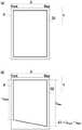
图1是用于对转印到记录媒体上的图像的平行度进行说明的概略图;FIG. 1 is a schematic diagram illustrating the parallelism of an image transferred to a recording medium;
图2是表示本实施方式所涉及的导电性辊的一例的概略立体图;2 is a schematic perspective view showing an example of a conductive roller according to this embodiment;
图3是表示本实施方式所涉及的导电性辊的一例的概略剖视图,是图1的A-A剖视图;3 is a schematic cross-sectional view showing an example of the conductive roller according to the present embodiment, and is a cross-sectional view taken along line A-A of FIG. 1;
图4是表示本实施方式所涉及的图像形成装置的一例的概略结构图;4 is a schematic configuration diagram showing an example of the image forming apparatus according to the present embodiment;
图5是表示本实施方式所涉及的图像形成装置的另一例的概略结构图;5 is a schematic configuration diagram showing another example of the image forming apparatus according to the present embodiment;
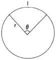
图6是用于对非咬合时的辊圆弧长度的计算方法进行说明的概略图。Fig. 6 is a schematic diagram for explaining a method of calculating the arc length of the rollers at the time of non-nipping.
符号说明Symbol Description
100-导电性辊,110-支承部件,122-弹性层,124-中间层,126-表面层,200-图像形成装置,206-曝光装置,207-感光体,208-带电辊,209-电源,211-显影装置,212-转印辊,213-清洁装置,214-除电装置,215-定影装置,500-记录纸,1Y、1M、1C、1K-感光体,2Y、2M、2C、2K-带电辊,3-曝光装置,3Y、3M、3C、3K-激光束,4Y、4M、4C、4K-显影装置,5Y、5M、5C、5K-一次转印辊,6Y、6M,6C、6K-感光体清洁装置,8Y、8M、8C、8K-色调剂盒,10Y、10M、10C、10K-图像形成单元,20-中间转印带,22-驱动辊,24-支承辊,26-二次转印辊,28-定影装置,30-中间转印带清洁装置,P-记录纸。100-conductive roller, 110-support member, 122-elastic layer, 124-intermediate layer, 126-surface layer, 200-image forming device, 206-exposure device, 207-photoreceptor, 208-charging roller, 209-power supply , 211-developing device, 212-transfer roller, 213-cleaning device, 214-static removal device, 215-fixing device, 500-recording paper, 1Y, 1M, 1C, 1K-photoreceptor, 2Y, 2M, 2C, 2K-charging roller, 3-exposure device, 3Y, 3M, 3C, 3K-laser beam, 4Y, 4M, 4C, 4K-developing device, 5Y, 5M, 5C, 5K-primary transfer roller, 6Y, 6M, 6C , 6K-photoreceptor cleaning device, 8Y, 8M, 8C, 8K-toner cartridge, 10Y, 10M, 10C, 10K-image forming unit, 20-intermediate transfer belt, 22-driving roller, 24-backup roller, 26 - Secondary transfer roller, 28 - Fixing device, 30 - Intermediate transfer belt cleaning device, P - Recording paper.
具体实施方式detailed description
以下,对本发明的实施方式进行说明。这些说明及实施例例示出实施方式,并不限制实施方式的范围。Embodiments of the present invention will be described below. These descriptions and examples illustrate embodiments and do not limit the scope of the embodiments.
本发明中使用“~”示出的数值范围表示将记载于“~”前后的数值分别作为最小值及最大值而包括的范围。The numerical range shown using "-" in this invention shows the range which includes the numerical value described before and after "-" as a minimum value and a maximum value, respectively.
在本发明中分阶段记载的数值范围中,在一个数值范围中记载的上限值或下限值可以替换为其他分阶段记载的数值范围的上限值或下限值。并且,在本发明中记载的数值范围中,该数值范围的上限值或下限值也可以置换为实施例中示出的值。In the numerical ranges described step by step in the present invention, the upper limit or lower limit described in one numerical range may be replaced by the upper limit or lower limit of the numerical range described in other steps. In addition, in the numerical range described in the present invention, the upper limit or lower limit of the numerical range may be replaced with the value shown in the Examples.
在本发明中,“工序”一词不仅包括独立的工序,而且即使在无法与其它工序明确区分的情况下,只要该工序达到预期的目的,则也包括在该术语中。In the present invention, the term "process" includes not only an independent process, but also included in the term as long as the process achieves the intended purpose even when it cannot be clearly distinguished from other processes.
在本发明中参考附图对实施方式进行说明的情况下,该实施方式的结构并不限定于附图中所示出的结构。并且,各图中的部件的大小是概念性大小,部件之间的大小的相对关系并不限定于此。In the case where the embodiments are described in the present invention with reference to the drawings, the configuration of the embodiments is not limited to the configurations shown in the drawings. In addition, the size of components in each figure is a conceptual size, and the relative size relationship between components is not limited thereto.
在本发明中,各成分可以包含复数种相应的物质。在本发明中,当提到组合物中的各成分的量时,在组合物中存在复数种与各成分相应的物质的情况下,除非另有说明,否则是指存在于组合物中的该复数种物质的总量。In the present invention, each component may contain a plurality of corresponding substances. In the present invention, when referring to the amount of each ingredient in the composition, in the case where there are a plurality of substances corresponding to each ingredient in the composition, unless otherwise specified, it refers to the amount of the ingredients present in the composition. The total amount of a plurality of substances.
<导电性辊><Conductive Roller>
本实施方式所涉及的导电性辊具有支承部件、配置于所述支承部件的外周面上的弹性层、配置于所述弹性层的外周面上的表层。The conductive roller according to this embodiment has a support member, an elastic layer arranged on the outer peripheral surface of the support member, and a surface layer arranged on the outer peripheral surface of the elastic layer.
而且,相对于导电性辊的外径的、具有与所述导电性辊的外径相同的外径的金属辊向所述导电性辊的压入量为1.7%时的所述导电性辊表面的收缩率为5%以上。Furthermore, the surface of the conductive roller when the pressing amount of the metal roller having the same outer diameter as the outer diameter of the conductive roller to the conductive roller is 1.7% relative to the outer diameter of the conductive roller The shrinkage rate is more than 5%.
在此,对收缩率的计算方法进行说明。Here, the calculation method of the shrinkage ratio will be described.
收缩率的测定是通过对导电性辊压入具有与导电性辊的外径相同的外径的金属辊(以下,有时简称为“金属辊”)而进行测定。具体的测定顺序如下所述。The shrinkage rate was measured by press-fitting a metal roll having the same outer diameter as that of the conductive roll (hereinafter, may be simply referred to as a "metal roll"). The specific measurement procedure is as follows.
“外径”是指与辊(例如导电性辊、金属辊等)的旋转轴正交的面上的辊剖面的直径。The "outer diameter" refers to the diameter of the cross section of the roll on the plane perpendicular to the rotation axis of the roll (for example, a conductive roll, a metal roll, etc.).
“金属辊”是由金属构成的辊,是指压入导电性辊时不引起形状变化的辊。The "metal roller" is a roller made of metal, and refers to a roller that does not change its shape when pressed into the conductive roller.
收缩率使用通过下述顺序测定的“咬合长度”及“非咬合时的辊圆弧长度”并通过下述式算出。The shrinkage rate was calculated by the following formula using "nip length" and "roll arc length at non-nip" measured by the following procedure.
式:(“非咬合时的辊圆弧长度”-“咬合长度”)÷(“非咬合时的辊圆弧长度”)×100Formula: ("Roll arc length at non-occlusion"-"Nocclusion length")÷("Roll arc length at non-occlusion")×100
咬合长度如下进行测定。The bite length was measured as follows.
在导电性辊的所述表面上涂布液体油墨,使导电性辊及金属辊隔着具有0.1mm厚度的纸(KOKUYO Co.,Ltd.制造、产品名称:KB用纸(彩色复印用))以各个辊的旋转轴平行的状态接触。另外,纸的大小设为大于导电性辊及金属辊形成的夹压面(当将金属辊压入导电性辊时,各个辊直接或者隔着具有0.1mm厚度的纸接触的面)。然后,使相对于导电性辊的外径的、金属辊向导电性辊的压入量(以下,有时也简称为“压入率”)成为1.7%。Liquid ink is applied on the surface of the conductive roller, and the conductive roller and the metal roller are interposed by a paper having a thickness of 0.1 mm (manufactured by KOKUYO Co., Ltd., product name: KB paper (for color copying)) Contact is made in a state where the rotation axes of the respective rollers are parallel. In addition, the size of the paper was set larger than the nip surface formed by the conductive roller and the metal roller (when the metal roller is pressed into the conductive roller, each roller contacts directly or through the paper having a thickness of 0.1 mm). Then, the indentation amount of the metal roller to the electroconductive roller (hereinafter, may be simply referred to as "indentation ratio") relative to the outer diameter of the electroconductive roller was set to 1.7%.
在此,“压入量”是金属辊从导电性辊表面向导电性辊侧压入并移动的距离。Here, the "pressing amount" is the distance by which the metal roller presses in from the surface of the conductive roller to the side of the conductive roller and moves.
然后,将金属辊从导电性辊及纸分离,并取出由导电性辊及金属辊夹持的纸。在取出的纸上转印有液体油墨,该液体油墨存在于以1.7%的压入率由导电性辊及金属辊形成的夹压面上。因此,通过测定转印到纸上的液体油墨图像的尺寸,能够测定1.7%的压入率的夹压面的尺寸。Then, the metal roller was separated from the conductive roller and the paper, and the paper sandwiched between the conductive roller and the metal roller was taken out. Liquid ink was transferred onto the taken out paper, and this liquid ink existed on the nip surface formed by the conductive roller and the metal roller at a penetration rate of 1.7%. Therefore, by measuring the size of the liquid ink image transferred to the paper, it is possible to measure the size of the nip surface at an indentation rate of 1.7%.
然后,当转印液体油墨时,在与导电性辊及金属辊的旋转轴正交的方向上测定相应的液体油墨图像的长度,并将该值设为“咬合长度”。Then, when the liquid ink is transferred, the length of the corresponding liquid ink image is measured in the direction perpendicular to the rotation axes of the conductive roller and the metal roller, and this value is set as "nip length".
非咬合时的辊圆弧长度如下所述算出。The roller arc length at the time of non-nipping was calculated as follows.
首先,在下述式中代入“与导电性辊的旋转轴正交的面上的导电性辊剖面的半径r(以下,也简称为“导电性辊的半径”)”及“压入量a”,算出接触圆弧角θ。First, the "radius r of the cross section of the conductive roller on the surface perpendicular to the rotation axis of the conductive roller (hereinafter, also simply referred to as the "radius of the conductive roller")" and the "indentation amount a" are substituted into the following formula. , Calculate the contact arc angle θ.
式:Cos(θ/2)=(r-a)/rFormula: Cos(θ/2)=(r-a)/r
a:压入量(单位:mm)a: Pressing amount (unit: mm)
r:导电性辊的半径(单位:mm)r: radius of conductive roller (unit: mm)
θ:接触圆弧角θ(单位:°)θ: contact arc angle θ (unit: °)
在使导电性辊及金属辊以压入量a接触的情况下,当观察与导电性辊的旋转轴正交的面上的导电性辊剖面时,由上述式算出的接触圆弧角θ相当于两条直线形成的角的大小(角度),所述两条直线通过直线来连接导电性辊及金属辊接触的区域的末端2点和导电性辊的旋转轴而形成。When the conductive roller and the metal roller are brought into contact with the pressing amount a, the contact arc angle θ calculated from the above formula is equivalent to The size (angle) of the angle formed by two straight lines formed by connecting the two ends of the area where the conductive roller and the metal roller are in contact with the rotation axis of the conductive roller with a straight line.
然后,如图6所示,关于非咬合时的辊圆弧长度,计算与导电性辊的半径r相同的半径及中心核与接触圆弧角θ相同的角度的扇形圆弧长度l,并将圆弧长度l设为非咬合时的辊圆弧长度。Then, as shown in FIG. 6, regarding the roller arc length at the time of non-nipping, calculate the arc length l of the sector having the same radius as the radius r of the conductive roller and the same angle between the center core and the contact arc angle θ, and The arc length l was defined as the arc length of the rollers at the time of non-nipping.
另外,扇形圆弧长度l的计算公式如下述式。In addition, the formula for calculating the sector arc length l is as follows.
式:l=2πr×θ/360Formula: l=2πr×θ/360
由上述式可知,将扇形圆弧长度l设为非咬合时的辊圆弧长度。It can be seen from the above formula that the arc length l of the fan shape is defined as the arc length of the rollers at the time of non-nipping.
本实施方式所涉及的导电性辊只要是将外周面按压于对置辊上并形成使记录媒体插通的插通部,并且用于通过插通部将图像转印到记录媒体上的导电性辊,则用途不受特别的限制。即,本实施方式所涉及的导电性辊用于将其外周面按压于对置辊上,将该按压区域作为插通部使记录媒体插通,并通过该插通部将图像转印到记录媒体上。As long as the conductive roller according to this embodiment is a conductive roller that presses the outer peripheral surface against the facing roller to form a penetration portion through which the recording medium is inserted, and is used to transfer an image to the recording medium through the penetration portion, roll, the use is not particularly limited. That is, the conductive roller according to this embodiment is used to press the outer peripheral surface of the conductive roller against the counter roller, use the pressing area as an insertion portion to insert the recording medium, and transfer the image to the recording medium through the insertion portion. on the media.
本实施方式所涉及的导电性辊例如例如优选使用于电子照相方式的图像形成装置中的转印辊。另外,本实施方式所涉及的导电性辊的用途并不限定于上述内容,可以举出一次转印辊、二次转印辊、支承辊等。The conductive roller according to the present embodiment is preferably used, for example, as a transfer roller in an electrophotographic image forming apparatus. In addition, the use of the conductive roller according to the present embodiment is not limited to the above, and examples thereof include a primary transfer roller, a secondary transfer roller, a backup roller, and the like.
本实施方式所涉及的导电性辊根据上述结构,容易提高转印到记录媒体上的图像的平行度。该理由推测为如下。The conductive roller according to this embodiment can easily improve the parallelism of the image transferred to the recording medium according to the above configuration. The reason is presumed as follows.
将导电性辊的外周面按压于对置辊上,并形成使记录媒体插通的插通部,在通过插通部将图像转印到记录媒体的情况下,转印到记录媒体上的图像的平行度可能会降低。The outer peripheral surface of the conductive roller is pressed against the opposing roller to form an insertion portion through which the recording medium is inserted. When the image is transferred to the recording medium through the insertion portion, the image transferred to the recording medium parallelism may be reduced.
在此,被转印的图像的平行度是指,图像相对于与插通部中的记录媒体P的输送方向(图1(a)的及图1的(b)中的箭头Y方向)正交的方向(图1的(a)及图1的(b)中的箭头X方向)的平行程度。具体而言,如图1的(a)所示,例如在欲对记录媒体P形成由分别与记录媒体P的各边平行的边构成的矩形图像G1的情况下,被转印的图像的平行度由在实际转印到记录媒体P上的图像G2中产生的如图1的(b)所示的箭头X方向一端侧(图1中标记为Front)的线图像长度LFront与另一端侧(图1中标记为Rear)的线图像长度LRear之差ΔL(=LFront-LRear)表示。Here, the parallelism of the transferred image means that the image is positively aligned with respect to the transport direction of the recording medium P in the insertion portion (arrow Y direction in FIG. 1(a) and FIG. 1(b)). The degree of parallelism of the intersecting direction (arrow X direction in Fig. 1(a) and Fig. 1(b)). Specifically, as shown in (a) of FIG. 1 , for example, when a rectangular image G1 composed of sides parallel to each side of the recording medium P is intended to be formed on the recording medium P, the parallelism of the transferred image The degree is generated by the line image length LFront on one end side (marked as Front in FIG. 1 ) of the arrow X direction shown in (b) of FIG. 1 in the image G2 actually transferred to the recording medium P and the other end side The difference ΔL (=LFront −LRear ) of the line image length LRear (marked as Rear in FIG. 1 ) is represented.
作为上述ΔL的校正方法,可以举出如下方法:在导电性辊的轴向两端调整导电性辊向对置辊的压入量,在与记录媒体的输送方向正交的方向上使记录媒体的输送量产生差异。为了调节记录媒体的输送量,例如,优选当将导电性辊压入对置辊时导电性辊表面容易收缩,并且导电性辊表面的摩擦系数高。As a method of correcting the above-mentioned ΔL, the following method can be mentioned: adjust the pressing amount of the conductive roller to the opposite roller at both axial ends of the conductive roller, and adjust the recording medium in the direction perpendicular to the conveying direction of the recording medium. The delivery volume varies. In order to adjust the conveying amount of the recording medium, for example, it is preferable that the surface of the conductive roller shrinks easily when the conductive roller is pressed into the opposing roller, and the friction coefficient of the surface of the conductive roller is high.
当将导电性辊压入对置辊时,作为表面容易收缩的导电性辊,可以举出在最外层具有弹性发泡体的导电性辊。然而,在该结构的导电性辊中,导电性辊表面的摩擦系数容易变小,有时无法充分地调节记录媒体的输送量。另一方面,为了增大导电性辊表面的摩擦系数,若将摩擦系数高的树脂层设置于最外层,则当将导电性辊压入对置辊时,有时表面不易收缩。Examples of the conductive roller whose surface tends to shrink when the conductive roller is pressed into the opposing roller include a conductive roller having an elastic foam in the outermost layer. However, in the conductive roller having such a structure, the friction coefficient of the conductive roller surface tends to be small, and the conveying amount of the recording medium cannot be adjusted sufficiently in some cases. On the other hand, in order to increase the friction coefficient of the surface of the conductive roller, if a resin layer having a high friction coefficient is provided on the outermost layer, the surface may not easily shrink when the conductive roller is pressed into the opposing roller.
如此,现有的导电性辊有时不易将表面的收缩性及表面的摩擦系数一同设为优选方式。In this way, it may be difficult for conventional conductive rollers to make both the surface shrinkability and the surface friction coefficient an optimal aspect.
本实施方式所涉及的导电性辊具有支承部件、配置于所述支承部件的外周面上的弹性层、配置于所述弹性层的外周面上的表层。通过具有配置在弹性层的外周面上的表层,导电性辊表面的摩擦系数容易提高。The conductive roller according to this embodiment has a support member, an elastic layer arranged on the outer peripheral surface of the support member, and a surface layer arranged on the outer peripheral surface of the elastic layer. By having the surface layer arranged on the outer peripheral surface of the elastic layer, the coefficient of friction of the surface of the conductive roller can be easily increased.
并且,在本实施方式所涉及的导电性辊中,相对于导电性辊的外径的、具有与导电性辊的外径相同的外径的金属辊向导电性辊的压入量为1.7%时的所述导电性辊表面的收缩率为5%以上。通过将所述收缩率设为5%以下,导电性辊表面变得容易收缩。In addition, in the conductive roller according to the present embodiment, the amount of pressing into the conductive roller by the metal roller having the same outer diameter as the outer diameter of the conductive roller with respect to the outer diameter of the conductive roller is 1.7%. The shrinkage rate of the surface of the conductive roller is 5% or more. By setting the shrinkage rate to 5% or less, the surface of the conductive roller tends to shrink.
因此,推测为本实施方式所涉及的导电性辊容易提高转印到记录媒体上的图像的平行度。Therefore, it is presumed that the conductive roller according to the present embodiment tends to improve the parallelism of the image transferred onto the recording medium.
参考附图对本实施方式所涉及的导电性辊进行说明。The conductive roller according to this embodiment will be described with reference to the drawings.
图2是表示本实施方式所涉及的导电性辊的一例的概略立体图。图3是图2的A-A剖视图,是将图2中图示的导电性辊沿径向切断的剖视图。FIG. 2 is a schematic perspective view showing an example of a conductive roller according to this embodiment. Fig. 3 is a cross-sectional view taken along line A-A of Fig. 2, and is a cross-sectional view taken along the radial direction of the conductive roller shown in Fig. 2 .
如图2所示,导电性辊100是包括圆柱状支承部件110和层状物120而构成的辊部件,所述层状物120配置于支承部件110的外周面上,并包括弹性层及表层。As shown in FIG. 2 , the
在此,表层可以是单层,也可以由复数个层构成。Here, the surface layer may be a single layer or may be composed of a plurality of layers.
在表层由复数个层构成的情况下,如图3所示,导电性辊100的层结构可以举出例如具有配置在圆柱状支承部件110的外周面上的弹性层122、配置在弹性层122的外周面上的中间层124、配置在中间层124的外周面上的表面层126的层结构。在表层由复数个层构成的情况下,在本实施方式所涉及的导电性辊中,例如,优选由中间层124和表面层126构成表层。When the surface layer is composed of a plurality of layers, as shown in FIG. 3 , the layer structure of the
本实施方式所涉及的导电性辊并不限定于图2及图3所示结构,例如也可以在支承部件110与弹性层122之间、弹性层122与中间层124之间、中间层124与表面层126之间适当地具有粘接层。The conductive roller according to this embodiment is not limited to the structure shown in FIG. 2 and FIG. The surface layers 126 suitably have an adhesive layer between them.
以下,对构成本实施方式所涉及的导电性辊的各层的材料等进行说明。Hereinafter, materials and the like of each layer constituting the conductive roller according to the present embodiment will be described.
[支承部件][support parts]
在本实施方式所涉及的导电性辊中,支承部件只要是作为导电性辊的支承部件发挥作用的部件即可。In the conductive roller according to this embodiment, the supporting member may be any member as long as it functions as a supporting member of the conductive roller.
支承部件可以是中空部件(即,圆筒状部件),也可以是实心部件(即,圆柱状部件)。The supporting member may be a hollow member (ie, a cylindrical member) or a solid member (ie, a cylindrical member).
另外,当形成导电性辊与对置辊之间的电场时,支承部件例如优选为导电性支承部件。In addition, when forming an electric field between the conductive roller and the opposing roller, the supporting member is preferably a conductive supporting member, for example.
作为导电性支承部件,例如可以举出铁(快削钢等)、铜、黄铜、不锈钢、铝、镍等金属部件;对外侧表面实施了电镀处理的树脂部件或陶瓷部件;含有导电剂的树脂部件或陶瓷部件。As the conductive supporting member, for example, metal parts such as iron (free-cutting steel, etc.), copper, brass, stainless steel, aluminum, nickel; resin parts or ceramic parts that have been subjected to plating treatment on the outer surface; Resin parts or ceramic parts.
支承部件的外径只要根据导电性辊的用途来确定即可。The outer diameter of the support member may be determined according to the use of the conductive roller.
例如,若本实施方式所涉及的导电性辊是二次转印辊,则作为一例,可以举出支承部件的外径为3mm以上且30mm以下。For example, if the conductive roller according to the present embodiment is a secondary transfer roller, as an example, the outer diameter of the supporting member may be 3 mm or more and 30 mm or less.
[弹性层][elastic layer]
弹性层例如包括弹性材料、导电剂,以及根据需要包括其他添加剂而构成。The elastic layer includes, for example, an elastic material, a conductive agent, and other additives as needed.
作为弹性材料,例如可以举出异戊二烯橡胶、氯丁橡胶、环氧氯丙烷橡胶、丁基橡胶、聚氨酯、硅橡胶、氟橡胶、苯乙烯-丁二烯橡胶、丁二烯橡胶、丁腈橡胶、乙烯丙烯橡胶、环氧氯丙烷-环氧乙烷共聚橡胶、环氧氯丙烷-环氧乙烷-烯丙基缩水甘油醚三元共聚橡胶、乙烯-丙烯-二烯3元共聚橡胶(EPDM)、丙烯腈-丁二烯共聚橡胶(NBR)、天然橡胶及将这些混合而成的橡胶等。Examples of elastic materials include isoprene rubber, neoprene rubber, epichlorohydrin rubber, butyl rubber, polyurethane, silicone rubber, fluororubber, styrene-butadiene rubber, butadiene rubber, butadiene rubber, Nitrile rubber, ethylene propylene rubber, epichlorohydrin-ethylene oxide copolymer rubber, epichlorohydrin-ethylene oxide-allyl glycidyl ether ternary copolymer rubber, ethylene-propylene-diene 3-component copolymer rubber (EPDM), acrylonitrile-butadiene copolymer rubber (NBR), natural rubber and rubber mixed with these, etc.
作为导电剂,可以举出电子导电剂、离子导电剂等。作为电子导电剂的例子,可以举出科琴黑、乙炔黑等炭黑;热分解碳、石墨;铝、铜、镍、不锈钢等各种导电性金属或合金;氧化锡、氧化铟、氧化钛、氧化锡-氧化锑固溶体、氧化锡-氧化铟固溶体等各种导电性金属氧化物;对绝缘物质的表面进行了导电化处理的物质;等粉末。并且,作为离子导电剂的例子,可以举出四乙基铵、月桂基三甲基铵等高氯酸盐、氯酸盐等;锂、镁等碱金属、碱土类金属的高氯酸盐、氯酸盐等。Examples of the conductive agent include electron conductive agents, ion conductive agents, and the like. Examples of electronic conductive agents include carbon black such as Ketjen black and acetylene black; pyrolytic carbon and graphite; various conductive metals or alloys such as aluminum, copper, nickel, and stainless steel; tin oxide, indium oxide, and titanium oxide. , various conductive metal oxides such as tin oxide-antimony oxide solid solution, tin oxide-indium oxide solid solution; substances that have conducted conductive treatment on the surface of insulating materials; and other powders. In addition, examples of the ion-conducting agent include perchlorates such as tetraethylammonium and lauryltrimethylammonium, chlorates, etc.; alkali metals such as lithium and magnesium, and perchlorates of alkaline earth metals; Chlorate etc.
这些导电剂可以单独使用,也可以组合两种以上使用。These conductive agents may be used alone or in combination of two or more.
作为其他添加剂,例如可以举出软化剂、增塑剂、固化剂、硫化剂、硫化促进剂、抗氧化剂、表面活性剂、偶联剂、填充剂(二氧化硅、碳酸钙等)等可添加于弹性体中的公知材料。Examples of other additives include softeners, plasticizers, curing agents, vulcanizing agents, vulcanization accelerators, antioxidants, surfactants, coupling agents, fillers (silicon dioxide, calcium carbonate, etc.) A well-known material in elastomers.
弹性层例如优选包括圆筒状弹性发泡体及覆盖所述弹性发泡体的露出面的导电性覆盖层而构成。The elastic layer preferably includes, for example, a cylindrical elastic foam and a conductive coating layer covering the exposed surface of the elastic foam.
这种结构的弹性层由导电性覆盖层赋予目标导电性,与使弹性发泡体中包含导电剂的情况相比,可以得到柔软的弹性层。于是,当将导电性辊压入对置辊时,容易成为表面容易收缩的导电性辊,并且容易成为更容易提高转印到记录媒体上的图像的平行度的导电性辊。The elastic layer having such a structure can be provided with target conductivity by the conductive covering layer, and a soft elastic layer can be obtained compared with the case where the elastic foam contains a conductive agent. Then, when the conductive roller is pressed into the opposing roller, the conductive roller tends to shrink the surface easily, and also tends to improve the parallelism of the image transferred to the recording medium more easily.
(弹性发泡体)(elastic foam)
构成弹性层的弹性发泡体是含有弹性材料(也称为橡胶材料)的发泡体。The elastic foam constituting the elastic layer is a foam containing an elastic material (also referred to as a rubber material).
作为弹性材料,适用所述弹性材料。As the elastic material, the elastic material described is suitable.
作为用于得到弹性发泡体的发泡剂,可以举出水;偶氮二酰胺、偶氮二异丁腈、重氮氨基苯等偶氮化合物;苯磺酰肼、4,4’-氧双苯磺酰肼、甲苯磺酰肼等苯磺酰肼类;通过热分解而产生碳酸气体的碳酸氢钠等重碳酸盐;产生氮气的NaNO2和NH4Cl的混合物;产生氧气的过氧化物;等。Examples of foaming agents used to obtain elastic foams include water; azo compounds such as azodicarbonamide, azobisisobutyronitrile, and diazoaminobenzene; benzenesulfonyl hydrazide, 4,4'-oxygen Benzenesulfonyl hydrazides such as bisbenzenesulfonyl hydrazide and toluenesulfonyl hydrazide; sodium bicarbonate and other bicarbonates that generate carbonic acid gas through thermal decomposition; mixtures of NaNO2 and NH4 Cl that generate nitrogen; oxides; etc.
为了得到弹性发泡体,根据需要,可以使用发泡助剂、去沫剂、催化剂等。In order to obtain an elastic foam, a foaming aid, a defoamer, a catalyst, etc. can be used as needed.
从弹性层的导电性控制的观点考虑,弹性发泡体可以包含导电剂。From the viewpoint of controlling the conductivity of the elastic layer, the elastic foam may contain a conductive agent.
弹性发泡体中包含的导电剂可以举出电子导电剂及离子导电剂。Examples of the conductive agent contained in the elastic foam include electron conductive agents and ion conductive agents.
另外,从将导电性辊的收缩率设为优选范围的观点考虑,弹性发泡体中的导电剂(尤其是电子导电剂的情况下)的含有率例如相对于弹性发泡体的总质量为1质量%以下,优选为0.5质量%以下,更优选为0质量%以下。In addition, from the viewpoint of making the shrinkage rate of the conductive roller into a preferable range, the content rate of the conductive agent (especially in the case of an electronic conductive agent) in the elastic foam is, for example, 1% by mass or less, preferably 0.5% by mass or less, more preferably 0% by mass or less.
即,弹性发泡体中的电子导电剂例如越少越优选,假设即使在弹性发泡体中包含导电性粒子的情况下,电子导电剂的含有率也需要相对于弹性发泡体的总质量为1质量%以下。That is, the less the electronic conductive agent in the elastic foam, for example, the better. Even if the elastic foam contains conductive particles, the content of the electronic conductive agent needs to be equal to the total mass of the elastic foam. It is 1 mass % or less.
另外,若在弹性发泡体中包含上述电子导电剂、填充剂等粒状物,则弹性层的硬度提高,介质的剥离性趋于降低。因此,弹性发泡体中的粒状物例如越少越优选,假设即使在弹性发泡体中包含粒状物的情况下,粒状物的总含有率相对于弹性发泡体的总质量也例如优选为1质量%以下。In addition, if the elastic foam contains granular substances such as the above-mentioned electronic conductive agent and filler, the hardness of the elastic layer increases, and the peelability of the medium tends to decrease. Therefore, the less granular matter in the elastic foam, for example, the better. Even when the elastic foam contains granular matter, the total content of the granular matter relative to the total mass of the elastic foam is preferably, for example, 1% by mass or less.
从导电性覆盖层的形成性的观点、以及设为容易提高转印到记录媒体上的图像的平行度的导电性辊的观点考虑,弹性发泡体中的气泡结构例如更优选为连续气泡结构。The cell structure in the elastic foam is more preferably an open cell structure, for example, from the viewpoint of the formability of the conductive coating layer and the conductive roller that can easily improve the parallelism of the image transferred to the recording medium. .
在此,连续气泡结构是指相邻的单元(即,气泡)连通,并且连通的单元的一部分在表面露出(开放)的结构。Here, the interconnected cell structure refers to a structure in which adjacent cells (that is, cells) communicate and part of the connected cells are exposed (opened) on the surface.
并且,在弹性发泡体中,独立气泡率例如越少越优选,独立气泡率例如优选为50%以下(更优选为30%以下)。In addition, in the elastic foam, the smaller the closed cell ratio is, for example, the better, and the closed cell ratio is preferably, for example, 50% or less (more preferably 30% or less).
从导电性覆盖层的形成性的观点、以及设为容易提高转印到记录媒体上的图像的平行度的导电性辊的观点考虑,弹性发泡体的单元直径(也称为气泡直径)例如优选为50μm以上且1000μm以下,更优选为100μm以上且800μm以下,进一步优选为150μm以上且600μm以下。From the viewpoint of the formability of the conductive coating layer and the conductive roller that can easily improve the parallelism of the image transferred to the recording medium, the cell diameter (also referred to as the cell diameter) of the elastic foam is, for example, It is preferably 50 μm or more and 1000 μm or less, more preferably 100 μm or more and 800 μm or less, and still more preferably 150 μm or more and 600 μm or less.
从导电性覆盖层的形成性的观点、以及设为容易提高转印到记录媒体上的图像的平行度的导电性辊的观点考虑,弹性发泡体的密度(也称为气泡率)例如优选为50kg/m3以上且90kg/m3以下,更优选为55kg/m3以上且85kg/m3以下,进一步优选为60kg/m3以上且80kg/m3以下。From the viewpoint of the formability of the conductive coating layer and the conductive roller that can easily improve the parallelism of the image transferred to the recording medium, the density of the elastic foam (also referred to as the cell ratio) is preferably, for example, It is 50 kg/m3 to 90 kg/m3 , more preferably 55 kg/m3 to 85 kg/m3 , still more preferably 60 kg/m3 to 80 kg/m3 .
在此,如下测定弹性发泡体中的单元直径(气泡直径)、发泡率(气泡率)及独立气泡率。Here, the cell diameter (cell diameter), expansion rate (cell rate) and closed cell rate in the elastic foam were measured as follows.
首先,使用剃刀制作弹性层(弹性层中的弹性泡沫)的厚度方向的剖面。与导电性辊的轴向平行且在圆周方向上以90°刻度制作共4个剖面。First, a section in the thickness direction of the elastic layer (elastic foam in the elastic layer) was made using a razor. A total of 4 sections were made parallel to the axial direction of the conductive roller and at a 90° scale in the circumferential direction.
用激光显微镜(EYENCE CORPORATION.、VK-X200)拍摄剖面的轴向中央部而获取图像。用图像分析软件(Media Cybernetics,Inc.、Image-Pro Plus)分析图像,并测定单元(气泡)的最大直径及面积。The axial central part of the section was photographed with a laser microscope (EYENCE CORPORATION., VK-X200) to obtain an image. Images were analyzed with image analysis software (Media Cybernetics, Inc., Image-Pro Plus), and the maximum diameter and area of cells (bubbles) were determined.
另外,在弹性发泡体具有连续气泡结构的情况下,根据连续气泡的形状推测单元(气泡)的连续状态,将连续(连结)的各个单元模拟分离,求出分离的单元的最大直径。即,若推测为连续气泡例如呈5个气泡连续(连结)的形状,则将5个单元模拟分离成5个,并测定分离的5个单元的最大直径。In addition, when the elastic foam has an open cell structure, the continuous state of the cells (cells) is estimated from the shape of the open cells, each continuous (connected) cell is simulated and separated, and the maximum diameter of the separated cell is obtained. That is, if the continuous bubbles are presumed to have a continuous (connected) shape of, for example, 5 bubbles, 5 cells are simulated to be separated into 5, and the maximum diameter of the 5 separated cells is measured.
单元直径设为在经分析的剖面图像中计算随机选择的100个单元的最大直径的算术平均,并根据所得到的值计算4个剖面的算术平均得到的值。The cell diameter is set to a value obtained by calculating the arithmetic mean of the maximum diameters of 100 randomly selected cells in the analyzed cross-sectional images, and calculating the arithmetic mean of four cross-sections based on the obtained value.
发泡率通过(经分析的剖面图像中的单元的总面积)/(经分析的剖面图像的总面积)×100而求出。The foaming ratio was obtained by (total area of cells in analyzed cross-sectional image)/(total area of analyzed cross-sectional image)×100.
独立气泡率通过(经分析的剖面图像中的独立气泡的总面积)/(经分析的剖面图像中的气泡的总面积)×100而求出。The independent cell ratio was obtained by (total area of independent cells in the analyzed cross-sectional image)/(total area of air cells in the analyzed cross-sectional image)×100.
在此,独立气泡设为在剖面图像中全部被壁面包围的气泡。Here, the independent air bubbles are air bubbles completely surrounded by wall surfaces in the cross-sectional image.
并且,弹性发泡体的密度如下测定。And, the density of the elastic foam was measured as follows.
使用弹性层(弹性层中的弹性发泡体),并使用剃刀制作立方体。立方体制作得尽可能大才能够准确地测定密度。接着,测定立方体的长度、宽度、高度,计算体积,测定重量,并由重量/体积求出密度。Use the elastic layer (elastic foam in the elastic layer) and use a razor to make the cubes. The cubes are made as large as possible to be able to accurately determine the density. Next, the length, width, and height of the cube are measured, the volume is calculated, the weight is measured, and the density is obtained from the weight/volume.
-弹性发泡体的形成--Formation of elastic foam-
圆筒状弹性发泡体的形成方法不受特别的限制,而可以使用公知方法。The method for forming the cylindrical elastic foam is not particularly limited, and known methods can be used.
例如,可以举出如下方法:制备包含弹性材料、发泡剂及根据需要使用的其他成分(例如硫化剂等)的组合物,在将该组合物挤出成型为圆筒状之后,加热成型物以使其硫化及发泡的方法;及从巨大的发泡体剪切成圆筒状的方法。For example, the method of preparing a composition containing an elastic material, a foaming agent, and other components (such as a vulcanizing agent, etc.) A method of vulcanizing and foaming it; and a method of cutting a huge foam into a cylindrical shape.
并且,也可以在形成圆柱状弹性发泡体之后,形成用于插入支承部件的中心孔而得到圆筒状弹性发泡体。Moreover, after forming a columnar elastic foam, the center hole for inserting a support member may be formed, and a cylindrical elastic foam may be obtained.
另外,在得到圆筒状弹性发泡体之后,根据需要,还可以调整形状,也可以进行研磨表面等后处理。In addition, after the cylindrical elastic foam is obtained, the shape may be adjusted as necessary, and post-treatments such as polishing the surface may be performed.
(导电性覆盖层)(conductive coating)
构成弹性层的导电性覆盖层是覆盖弹性发泡体的露出面(即,与弹性发泡体的大气的接触面,并且包括圆筒状弹性发泡体的内周面、外周面及单元壁面)的导电性层。The conductive covering layer that constitutes the elastic layer is to cover the exposed surface of the elastic foam (that is, the contact surface with the atmosphere of the elastic foam, and includes the inner peripheral surface, outer peripheral surface and cell wall surface of the cylindrical elastic foam. ) conductive layer.
弹性发泡体的露出面可以全部被导电性覆盖层覆盖,也可以一部分被覆盖。The exposed surface of the elastic foam may be covered entirely or partially with the conductive coating layer.
可以使用包含导电剂及树脂的处理液来形成导电性覆盖层。The conductive covering layer can be formed using a treatment liquid containing a conductive agent and a resin.
在此,作为用于处理液的导电剂,例如可以举出电子导电剂或离子导电剂,其中,例如优选为电子导电剂。Here, examples of the conductive agent used in the treatment liquid include electron conductive agents and ion conductive agents, among which, for example, electronic conductive agents are preferable.
处理液中包含的导电剂可以是一种,也可以是两种。The conductive agent contained in the treatment liquid may be one kind or two kinds.
在此,作为电子导电剂的例子,与弹性发泡体中包含的电子导电剂相同,优选方式也相同。Here, examples of the electron conductive agent are the same as those contained in the elastic foam, and preferred modes are also the same.
作为用于处理液的树脂,若为可以对弹性发泡体的露出面形成覆盖层的树脂,则不受特别的限制,例如可以举出丙烯酸树脂、氨基甲酸酯树脂、氟树脂、硅酮树脂等。这些树脂例如优选用作胶乳。The resin used for the treatment liquid is not particularly limited as long as it can form a coating layer on the exposed surface of the elastic foam, for example, acrylic resin, urethane resin, fluororesin, silicone resin etc. These resins are preferably used as latex, for example.
作为胶乳的例子,除了上述树脂的胶乳以外,可以举出天然橡胶胶乳、丁二烯橡胶胶乳、丙烯腈-丁二烯橡胶胶乳、丙烯酸橡胶胶乳、聚氨酯橡胶胶乳、氟橡胶胶乳、硅橡胶胶乳等。Examples of latex include natural rubber latex, butadiene rubber latex, acrylonitrile-butadiene rubber latex, acrylic rubber latex, polyurethane rubber latex, fluororubber latex, silicone rubber latex, etc. .
处理液例如优选为包含导电剂、树脂及水,即包含导电剂及树脂的水分散液。The treatment liquid is preferably, for example, an aqueous dispersion containing a conductive agent, a resin, and water, that is, a conductive agent and a resin.
处理液中的导电剂及树脂的浓度只要根据导电性覆盖层的形成性、对弹性层要求的电阻值等来确定即可。The concentrations of the conductive agent and the resin in the treatment liquid may be determined according to the formability of the conductive coating layer, the resistance value required for the elastic layer, and the like.
-导电性覆盖层的形成-- Formation of conductive coating layer -
对弹性发泡体赋予处理液,并通过加热干燥而形成导电性覆盖层。The treatment liquid was applied to the elastic foam, and dried by heating to form a conductive coating layer.
作为对弹性发泡体赋予处理液的方法,可以举出通过喷涂等对弹性发泡体涂布处理液的方法、将弹性发泡体浸渍于处理液中的方法等。Examples of the method of applying the treatment liquid to the elastic foam include a method of applying the treatment liquid to the elastic foam by spraying or the like, a method of immersing the elastic foam in the treatment liquid, and the like.
通过这些方法,处理液浸渍至弹性发泡体的表面及气泡内部。接着,通过加热等使附着有处理液的弹性发泡体干燥,由此形成导电性覆盖层。By these methods, the treatment liquid is impregnated into the surface of the elastic foam and the inside of the cells. Next, the elastic foam to which the treatment liquid is adhered is dried by heating or the like, thereby forming a conductive coating layer.
作为导电性覆盖层,例如可以适用在日本特开2009-244824号公报等中记载的覆盖层及其形成方法。As the conductive coating layer, for example, the coating layer described in JP-A-2009-244824 and its formation method can be applied.
如上所述,通过在弹性发泡体的露出面上形成导电性覆盖层而形成本实施方式所涉及的导电性辊中的弹性层。As described above, the elastic layer in the conductive roller according to this embodiment is formed by forming the conductive coating layer on the exposed surface of the elastic foam.
(弹性层的体积电阻值)(Volume resistance value of the elastic layer)
在本实施方式所涉及的导电性辊中,弹性层被施加10V电压时的体积电阻值例如优选为105Ω以下,更优选为101Ω以上且105Ω以下,进一步优选为102Ω以上且104Ω以下。In the conductive roller according to the present embodiment, the volume resistance value of the elastic layer when a voltage of 10 V is applied is, for example, preferably 105 Ω or less, more preferably 101 Ω or more and 105 Ω or less, still more preferably 102 Ω Above and below 104 Ω.
在此,弹性层的体积电阻值如下测定。Here, the volume resistance value of the elastic layer is measured as follows.
首先,在导电性支承部件的外周上制作具备作为测定对象的弹性层,使用所得到的辊部件测定弹性层的体积电阻值。另外,在本实施方式所涉及的导电性辊具备导电性支承部件的情况下,可以测定从该导电性辊剥除表层的辊部件。First, an elastic layer to be measured was produced on the outer periphery of a conductive support member, and the volume resistance value of the elastic layer was measured using the obtained roller member. Moreover, when the electroconductive roller which concerns on this embodiment has an electroconductive support member, the roller member which peeled off the surface layer from this electroconductive roller can be measured.
对辊部件的两端部各施加500g的荷载并将辊部件放置在铜板等金属板上,使用微电流测定器(ADVANTEST CORPORATION制造的R8320)对辊部件的导电性支承部件与金属板之间施加10V(弹性层的情况)的电压(V),读取5秒后的电流值I(A),并通过由下式计算而求出。Apply a load of 500 g to both ends of the roller member and place the roller member on a metal plate such as a copper plate, and apply a load between the conductive support member and the metal plate of the roller member using a microcurrent measuring device (R8320 manufactured by ADVANTEST CORPORATION). The voltage (V) of 10 V (in the case of the elastic layer) was read and the current value I (A) after 5 seconds was read and calculated by the following formula.
式:体积电阻值Rv(Ω)=V/IFormula: volume resistance value Rv (Ω) = V/I
另外,在温度22℃、湿度55%RH环境下进行测定。In addition, the measurement was performed in an environment with a temperature of 22° C. and a humidity of 55% RH.
(弹性层的厚度)(thickness of elastic layer)
在本实施方式所涉及的导电性辊中,弹性层的厚度只要根据导电性辊的用途来确定即可。In the conductive roller according to this embodiment, the thickness of the elastic layer may be determined according to the use of the conductive roller.
例如,若本实施方式所涉及的导电性辊是二次转印辊,则作为一例,可以举出弹性层的厚度为1mm以上且10mm以下。For example, if the conductive roller according to the present embodiment is a secondary transfer roller, an example in which the thickness of the elastic layer is not less than 1 mm and not more than 10 mm can be mentioned.
(表层)(surface layer)
在本实施方式所涉及的导电性辊中,在弹性层的外周面上配置有表层。In the conductive roller according to this embodiment, the surface layer is arranged on the outer peripheral surface of the elastic layer.
表层是构成导电性辊的最表面的层,由单层或复数个层构成。The surface layer is the outermost layer constituting the conductive roller, and is composed of a single layer or a plurality of layers.
以下,对表层(1)由单层构成的情况及(2)由复数个层构成的情况进行说明。Hereinafter, the case where the surface layer (1) consists of a single layer, and (2) the case where it consists of several layers is demonstrated.
-(1)由单层构成时的表层--(1) Surface layer when composed of a single layer-
表层是配置在弹性层的外周面上的层。The surface layer is a layer arranged on the outer peripheral surface of the elastic layer.
表层是有助于导电性辊的电阻调整的层,表层被施加100V电压时的体积电阻值例如优选为104Ω以上且109Ω以下(更优选为106Ω以上且109Ω以下)。The surface layer is a layer that contributes to the resistance adjustment of the conductive roller, and the volume resistance value of the surface layer when a voltage of 100 V is applied is preferably, for example, 104 Ω or more and 109 Ω or less (more preferably 106 Ω or more and 109 Ω or less). .
另外,表层的体积电阻值通过与弹性层的体积电阻值相同的方法而测定。In addition, the volume resistance value of the surface layer was measured by the same method as the volume resistance value of the elastic layer.
表层例如优选包含导电剂以实现上述体积电阻值。The surface layer, for example, preferably contains a conductive agent in order to achieve the above-mentioned volume resistance value.
作为导电剂而使用电子导电剂及离子导电剂中的任一种,但是从提高带电维持性的观点考虑,例如优选使用离子导电剂。As the conductive agent, either an electronic conductive agent or an ion conductive agent is used, but from the viewpoint of improving charge retention, for example, an ion conductive agent is preferably used.
即,表层例如优选包含离子导电剂。表层中包含的离子导电剂可以举出与弹性发泡体中包含的离子导电剂相同的离子导电剂,优选方式也相同。That is, the surface layer preferably contains, for example, an ion-conducting agent. Examples of the ion conductive agent contained in the surface layer include the same ion conductive agents as those contained in the elastic foam, and preferred modes are also the same.
离子导电剂可以单独使用一种,也可以组合两种以上而使用。The ion conductive agent may be used alone or in combination of two or more.
并且,作为用于表层的离子导电剂,也可以是具有离子导电能的高分子材料,例如环氧氯丙烷橡胶、环氧氯丙烷-环氧乙烷共聚橡胶、环氧氯丙烷-环氧乙烷-烯丙基缩水甘油醚三元共聚橡胶等。In addition, as the ion conductive agent used for the surface layer, it can also be a polymer material with ion conductivity, such as epichlorohydrin rubber, epichlorohydrin-ethylene oxide copolymer rubber, epichlorohydrin-ethylene oxide Alkane-allyl glycidyl ether ternary copolymer rubber, etc.
并且,作为用于表层的离子导电剂,可以是在树脂等高分子材料的末端上结合有离子导电剂的化合物。Furthermore, as the ion-conducting agent used for the surface layer, a compound in which the ion-conducting agent is bonded to the end of a polymer material such as resin may be used.
离子导电剂的含量只要在可实现上述体积电阻值的范围内即可。The content of the ion conductive agent should just be in the range which can realize the said volume resistance value.
另外,在表层包含粘接材料的情况下,离子导电剂的含量相对于粘接材料100质量份例如优选为0.1质量份以上且5.0质量份以下,更优选为0.5质量份以上且3.0质量份以下。In addition, when the surface layer contains an adhesive material, the content of the ion-conducting agent is, for example, preferably 0.1 to 5.0 parts by mass, more preferably 0.5 to 3.0 parts by mass relative to 100 parts by mass of the adhesive. .
表层除了离子导电剂以外,还可以包含粘接材料。The surface layer may contain an adhesive material in addition to the ion-conducting agent.
作为粘接材料不受特别的限制,可以举出可形成表层的树脂、弹性材料等。作为用于表层的树脂,可以举出氨基甲酸酯树脂、丙烯酸树脂、环氧树脂、硅酮树脂等。并且,作为表层中包含的弹性材料,使用与用于弹性层的弹性材料相同的材料。The adhesive material is not particularly limited, and examples thereof include resins, elastic materials, and the like that can form a surface layer. Examples of the resin used for the surface layer include urethane resin, acrylic resin, epoxy resin, silicone resin, and the like. Also, as the elastic material contained in the surface layer, the same material as that used for the elastic layer is used.
表层根据对表层要求的物性等可以包含其他添加剂。The surface layer may contain other additives depending on the physical properties required for the surface layer.
-(2)由复数个层构成时的表层--(2) Surface layer when composed of plural layers-
在表层由复数个层构成的情况下,例如,优选包括配置在弹性层的外周面上的中间层和配置在中间层的外周面上的表面层而构成。When the surface layer is composed of a plurality of layers, for example, it is preferably composed of an intermediate layer arranged on the outer peripheral surface of the elastic layer and a surface layer arranged on the outer peripheral surface of the intermediate layer.
·中间层·middle layer
中间层具有与由上述(1)单层构成时的表层相同的结构。The intermediate layer has the same structure as that of the surface layer when it is composed of the above (1) single layer.
·表面层· Surface layer
表面层是配置于中间层的外周面上的层,是构成导电性辊的最表面的层。The surface layer is a layer disposed on the outer peripheral surface of the intermediate layer, and constitutes the outermost layer of the conductive roller.
表面层由于与介质接触,因此例如优选具有脱模性。Since the surface layer is in contact with a medium, it is preferable to have mold release properties, for example.
表面层例如优选为包含树脂的层。The surface layer is preferably, for example, a layer containing a resin.
作为表面层中包含的树脂不受特别的限制,但是例如可以举出氨基甲酸酯树脂、聚酯树脂、酚醛树脂、丙烯酸树脂、环氧树脂、纤维素树脂等。The resin contained in the surface layer is not particularly limited, and examples thereof include urethane resins, polyester resins, phenolic resins, acrylic resins, epoxy resins, cellulose resins, and the like.
表面层例如优选包含导电剂。The surface layer preferably contains, for example, a conductive agent.
作为表面层中包含的导电剂,可以举出电子导电剂及离子导电剂。Examples of the conductive agent contained in the surface layer include electron conductive agents and ion conductive agents.
作为表面层中包含的电子导电剂,使用与用于导电性覆盖层的电子导电剂相同的电子导电剂。并且,作为表面层中包含的离子导电剂,使用与用于中间层的离子导电剂相同的离子导电剂。As the electron conductive agent contained in the surface layer, the same electron conductive agent as that used for the conductive covering layer is used. Also, as the ion-conducting agent contained in the surface layer, the same ion-conducting agent as that used for the intermediate layer is used.
在表面层包含树脂的情况下,离子导电剂的含量相对于表面层中包含的树脂100质量份例如优选为0.1质量份以上且5.0质量份以下,更优选为0.5质量份以上且3.0质量份以下。When the surface layer contains a resin, the content of the ion-conducting agent is, for example, preferably 0.1 to 5.0 parts by mass, more preferably 0.5 to 3.0 parts by mass with respect to 100 parts by mass of the resin contained in the surface layer. .
表面层根据对表面层要求的物性等可以包含其他添加剂。The surface layer may contain other additives depending on the physical properties required for the surface layer.
表面层被施加10V电压时的体积电阻值例如优选为104Ω以上且1014Ω以下,更优选为106Ω以上且1012Ω以下。The volume resistance value of the surface layer when a voltage of 10 V is applied is, for example, preferably not less than 104 Ω and not more than 1014 Ω, more preferably not less than 106 Ω and not more than 1012 Ω.
表面层的体积电阻值根据JIS K 6911(2006)如下测定。The volume resistance value of the surface layer is measured as follows according to JIS K 6911 (2006).
首先,制作使用了表面层材料的单层片,并使用所得到的单层片测定体积电阻率。片材的厚度例如优选为0.2mm厚度。在圆形电极之间(表面电极与背面电极之间),使用微电流测定器(ADVANTEST CORPORATION制造的R8320)对单层片施加10V电压(V),读取5秒后的电流值I(A),并由下式进行计算,由此求出体积电阻值。First, a single-layer sheet using a surface layer material was produced, and the volume resistivity was measured using the obtained single-layer sheet. The thickness of the sheet is, for example, preferably 0.2 mm thick. Between the circular electrodes (between the surface electrode and the back electrode), a microcurrent measuring device (R8320 manufactured by ADVANTEST CORPORATION) is used to apply a voltage (V) of 10 V to the single-layer sheet, and the current value I (A) after 5 seconds is read. ), and calculated by the following formula to obtain the volume resistance value.
式:体积电阻值Rv(Ω)=V/IFormula: volume resistance value Rv (Ω) = V/I
在本实施方式所涉及的导电性辊中,表面层的厚度只要根据导电性辊的用途来确定即可。In the conductive roller according to this embodiment, the thickness of the surface layer may be determined according to the use of the conductive roller.
例如,若本实施方式所涉及的导电性辊是二次转印辊,则作为一例,可以举出表面层的厚度为0.01mm以上且0.05mm以下。For example, if the conductive roller according to the present embodiment is a secondary transfer roller, as an example, the thickness of the surface layer is 0.01 mm to 0.05 mm.
表面层的杨氏模量例如优选为50MPa以上,更优选为50MPa以上且400MPa以下。The Young's modulus of the surface layer is, for example, preferably 50 MPa or more, more preferably 50 MPa or more and 400 MPa or less.
另外,表面层的杨氏模量测定方法如后所述。In addition, the measuring method of the Young's modulus of a surface layer is mentioned later.
表面层的形成方法不受特别的限制,例如可以举出在中间层上涂布表面层形成用涂布液,并使所得到的涂膜干燥的方法。The method for forming the surface layer is not particularly limited, and examples thereof include a method of applying a coating liquid for forming a surface layer on an intermediate layer and drying the obtained coating film.
(表层特性)(surface properties)
以下,对单层的表层及由复数个层构成的表层的特性进行说明。Hereinafter, the properties of a single-layer surface layer and a surface layer composed of a plurality of layers will be described.
-表层的摩擦系数--Friction coefficient of surface layer-
表层外周面的摩擦系数例如优选为0.2以上,更优选为0.3以上,进一步优选为0.4以上。The coefficient of friction of the outer peripheral surface of the surface layer is, for example, preferably 0.2 or higher, more preferably 0.3 or higher, and still more preferably 0.4 or higher.
表层外周面的摩擦系数的上限值不受特别的限定,但是从记录媒体的剥离性提高的观点考虑,例如,例如优选为0.7以下。The upper limit of the coefficient of friction of the outer peripheral surface of the surface layer is not particularly limited, but is preferably, for example, 0.7 or less from the viewpoint of improving the releasability of the recording medium.
通过将表层外周面的摩擦系数设为0.2以上,记录媒体的输送量的调节变得更容易。因此,容易成为更容易提高转印到记录媒体上的图像的平行度的导电性辊。By setting the coefficient of friction of the outer peripheral surface of the surface layer to 0.2 or more, it becomes easier to adjust the transport amount of the recording medium. Therefore, it becomes easy to become an electroconductive roller which improves the parallelism of the image transferred to a recording medium more easily.
表层外周面的摩擦系数是通过下述顺序测定的相对于SUS的摩擦系数。The friction coefficient of the outer peripheral surface of the surface layer is a friction coefficient against SUS measured by the following procedure.
具体而言,使用HEIDON公司制造的TRIBOGEAR-Type14FW测定静摩擦系数。测定位置设为导电性辊的轴向中央的1点。以相同的顺序沿周方向每120°测定3次,将所得到的3个测定值的算术平均值设为表层外周面的摩擦系数。Specifically, the coefficient of static friction was measured using TRIBOGEAR-Type 14FW manufactured by HEIDON. The measurement position was set at one point in the center of the axial direction of the conductive roller. The measurement was performed three times at every 120° in the circumferential direction in the same order, and the arithmetic mean value of the obtained three measurement values was defined as the coefficient of friction of the outer peripheral surface of the surface layer.
(厚度Ts、Tm)(thickness Ts, Tm)
表层为单层时的表层的厚度Ts、以及表层由复数个层构成时的中间层的厚度Tm例如优选为0.5mm以上且5mm以下,更优选为0.7mm以上且4mm以下,进一步优选为0.8mm以上且3mm以下。The thickness Ts of the surface layer when the surface layer is a single layer and the thickness Tm of the intermediate layer when the surface layer is composed of multiple layers are, for example, preferably 0.5 mm to 5 mm, more preferably 0.7 mm to 4 mm, and even more preferably 0.8 mm. Above and below 3mm.
通过将表层的厚度Ts及中间层的厚度Tm设在0.5mm以上且5mm以下的范围内,当将导电性辊压入对置辊时,导电性辊表面变得更容易收缩。因此,容易成为更容易提高转印到记录媒体上的图像的平行度的导电性辊。By setting the thickness Ts of the surface layer and the thickness Tm of the intermediate layer in the range of 0.5 mm to 5 mm, the surface of the conductive roller becomes easier to shrink when the conductive roller is pressed into the opposing roller. Therefore, it becomes easy to become an electroconductive roller which improves the parallelism of the image transferred to a recording medium more easily.
(导电性辊的特性)(Characteristics of Conductive Roller)
相对于导电性辊的外径的、具有与导电性辊的外径相同的外径的金属辊向所述导电性辊的压入量为1.7%时的导电性辊表面的收缩率为5%以上。The shrinkage rate of the surface of the conductive roller is 5% when the pressing amount of the metal roller having the same outer diameter as the outer diameter of the conductive roller is 1.7% relative to the outer diameter of the conductive roller above.
另外,收缩率的计算方法如上所述。In addition, the calculation method of a shrinkage rate is as above-mentioned.
当将导电性辊压入对置辊时,导电性辊表面变得更容易收缩,从成为更容易提高转印到记录媒体上的图像的平行度的导电性辊的观点考虑,当压入率为1.7%时,所述导电性辊表面的收缩率例如优选为5%以上且20%以下,更优选为6%以上且15%以下,进一步优选为7%以上且10%以下。When the conductive roller is pressed into the opposing roller, the surface of the conductive roller becomes easier to shrink, and from the viewpoint of making it easier to improve the parallelism of the image transferred to the recording medium, when the pressing ratio When it is 1.7%, the shrinkage ratio of the surface of the conductive roller is, for example, preferably 5% to 20%, more preferably 6% to 15%, and still more preferably 7% to 10%.
(杨氏模量)(Young's modulus)
在表层为单层的情况下,弹性层的杨氏模量Yd、以及表层的杨氏模量Ys例如优选满足下述式(1-1)。When the surface layer is a single layer, the Young's modulus Yd of the elastic layer and the Young's modulus Ys of the surface layer preferably satisfy the following formula (1-1), for example.
并且,在表层由复数个层构成的情况下,弹性层的杨氏模量Yd、以及中间层的杨氏模量Ym例如优选满足下述式(2-1)。Furthermore, when the surface layer is composed of a plurality of layers, the Young's modulus Yd of the elastic layer and the Young's modulus Ym of the intermediate layer preferably satisfy the following formula (2-1), for example.
式(1-1):Yd<YsFormula (1-1): Yd<Ys
式(2-1):Yd<Ym。Formula (2-1): Yd<Ym.
由杨氏模量满足上述式,因此中间层及表层容易变形为く字形,因此咬合部的收缩变得容易。因此,由于咬合部的收缩变大,因此容易成为更容易提高转印到记录媒体上的图像的平行度的导电性辊。Since the Young's modulus satisfies the above formula, the middle layer and the surface layer are easily deformed into a "く" shape, so the contraction of the occlusal part becomes easy. Therefore, since the shrinkage of the nip part becomes large, it becomes easy to become a conductive roller that can more easily improve the parallelism of the image transferred to the recording medium.
在表层为单层的情况下,弹性层的杨氏模量Yd、以及表层的杨氏模量Ys例如优选满足下述式(1-2)。When the surface layer is a single layer, the Young's modulus Yd of the elastic layer and the Young's modulus Ys of the surface layer preferably satisfy the following formula (1-2), for example.
并且,在表层由复数个层构成的情况下,弹性层的杨氏模量Yd、以及中间层的杨氏模量Ym例如优选满足下述式(2-2)。Furthermore, when the surface layer is composed of a plurality of layers, the Young's modulus Yd of the elastic layer and the Young's modulus Ym of the intermediate layer preferably satisfy the following formula (2-2), for example.
式(1-2):10≤Ys/Yd≤10000Formula (1-2): 10≤Ys/Yd≤10000
式(2-2):10≤Ym/Yd≤1000。Formula (2-2): 10≤Ym/Yd≤1000.
由于杨氏模量满足上述式,因此因柔软的弹性层而不阻碍中间层及表层的变形而产生咬合部的收缩,因此容易成为更容易提高转印到记录媒体上的图像的平行度的导电性辊。Since the Young's modulus satisfies the above formula, the soft elastic layer does not hinder the deformation of the middle layer and the surface layer to cause the shrinkage of the joint, so it is easy to become a conductive material that is easier to improve the parallelism of the image transferred to the recording medium. sex roll.
从容易成为进一步容易提高转印到记录媒体上的图像的平行度的导电性辊的观点考虑,Yd及Ys例如更优选满足下述式(1-3),进一步优选满足下述(1-4)。From the viewpoint of being easy to become a conductive roller that further improves the parallelism of the image transferred onto the recording medium, Yd and Ys, for example, more preferably satisfy the following formula (1-3), and further preferably satisfy the following formula (1-4) ).
式(1-3):15≤Ys/Yd≤9000Formula (1-3): 15≤Ys/Yd≤9000
式(1-4):20≤Ys/Yd≤8000Formula (1-4): 20≤Ys/Yd≤8000
从容易成为进一步容易提高转印到记录媒体上的图像的平行度的导电性辊的观点考虑,Yd及Ym例如更优选满足下述式(2-3),进一步优选满足下述式(2-4)。From the viewpoint of being easy to become a conductive roller that further improves the parallelism of the image transferred onto the recording medium, Yd and Ym, for example, more preferably satisfy the following formula (2-3), and further preferably satisfy the following formula (2-3). 4).
式(2-3):15≤Ym/Yd≤900Formula (2-3): 15≤Ym/Yd≤900
式(2-4):20≤Ym/Yd≤800Formula (2-4): 20≤Ym/Yd≤800
各层的杨氏模量如下测定。The Young's modulus of each layer was measured as follows.
各层的杨氏模量的测定方法基本上依据ISO527。The measuring method of the Young's modulus of each layer is basically based on ISO527.
关于中间层及弹性层,制作标线间距为50mm、弹性层的厚度为5mm、中间层的厚度为1mm的哑铃型拉伸试验片,用台式精密万能试验机(AGS-X;SHIMADZU CORPORATION制造)求出拉伸速度为5mm/min时的应力(σ)应变(ε)曲线,测定0.05%~0.25%应变时的应力,并由Δσ/Δε求出杨氏模量。Regarding the intermediate layer and the elastic layer, a dumbbell-shaped tensile test piece with a marking distance of 50 mm, a thickness of the elastic layer of 5 mm, and a thickness of the intermediate layer of 1 mm was produced, and a desktop precision universal testing machine (AGS-X; manufactured by SHIMADZU CORPORATION) was used. Obtain the stress (σ) strain (ε) curve when the tensile speed is 5 mm/min, measure the stress when the strain is 0.05% to 0.25%, and obtain the Young's modulus from Δσ/Δε.
在表面层的杨氏模量的情况下,分析表面层的组合,并通过用氟树脂制模具进行涂布形成及煅烧,制作标线间距为50mm、厚度为0.2mm的具有与表面层相同组合的哑铃型拉伸试验片,除了使用该试验片以外,以与中间层及弹性层的杨氏模量的测定方法相同的方法求出。In the case of the Young's modulus of the surface layer, the combination of the surface layer was analyzed, and by coating formation and firing with a mold made of fluororesin, a product with the same combination as the surface layer was produced with a marking distance of 50 mm and a thickness of 0.2 mm. The dumbbell-shaped tensile test piece was obtained by the same method as the measurement method of the Young's modulus of the intermediate layer and the elastic layer, except that the test piece was used.
(导电性辊的体积电阻值)(Volume resistance value of conductive roller)
本实施方式所涉及的导电性辊中,在被施加1000V电压时的体积电阻值例如优选为104Ω以上且1012Ω以下,更优选为105Ω以上且1011Ω以下,进一步优选为106Ω以上且1010Ω以下。In the conductive roller according to the present embodiment, the volume resistance value when a voltage of 1000 V is applied is, for example, preferably 104 Ω or more and 1012 Ω or less, more preferably 105 Ω or more and 1011 Ω or less, still more preferably 106 Ω or more and 1010 Ω or less.
导电性辊的体积电阻值通过与弹性层的体积电阻值相同的方法而测定。The volume resistance value of the conductive roller is measured by the same method as the volume resistance value of the elastic layer.
<图像形成装置、转印装置、处理盒><Image forming device, transfer device, process cartridge>
图4是表示作为本实施方式所涉及的图像形成装置的一例的直接转印方式的图像形成装置的概略结构图。4 is a schematic configuration diagram showing an image forming apparatus of a direct transfer method as an example of the image forming apparatus according to the present embodiment.
图4所示的图像形成装置200具备:感光体207(图像保持体的一例);带电辊208(带电装置的一例),使感光体207的表面带电;曝光装置206(静电荷图像形成装置的一例),在带电的感光体207的表面上形成静电荷图像;显影装置211(显影装置的一例),由包含色调剂的显影剂将形成于感光体207的表面上的静电荷图像显影为色调剂图像;及转印辊212(转印装置的一例、本实施方式所涉及的转印装置的一例)感光体,将形成于207的表面上的色调剂图像转印到记录媒体的表面。The
在此,将本实施方式所涉及的导电性辊适用于转印辊212,该转印辊212将外周面按压于相当于对置辊的感光体207,并形成使记录纸500插通的插通部。Here, the conductive roller according to this embodiment is applied to the
图4所示的图像形成装置200还具备:清洁装置213,除去残留在感光体207的表面上的色调剂;除电装置214,对感光体207的表面进行除电;及定影装置215(定影单元的一例),使色调剂图像定影于记录媒体。The
带电辊208可以是接触带电方式,也可以是非接触带电方式。电压从电源209施加到带电辊208。The charging
作为曝光装置206,可以举出具备半导体激光器、LED(Light Emitting Diode:发光二极管)等光源的光学装置。Examples of the
显影装置211是将色调剂供给到感光体207的装置。显影装置211例如使辊状显影剂保持体接触或接近于感光体207,以使色调剂附着于感光体207上的静电荷图像,从而形成色调剂图像。The developing
转印辊212是直接接触到记录媒体的表面的转印辊,其配置在与感光体207对置的位置。记录纸500(记录媒体的一例)经由供给机构供给到转印辊212与感光体207接触的间隙。若转印偏压施加到转印辊212,则从感光体207朝向记录纸500的静电力作用于色调剂图像,感光体207上的色调剂图像转印到记录纸500上。The
作为定影装置215,例如可以举出具备加热辊和按压于该加热辊上的加压辊的加热定影装置。As the
作为清洁装置213,可以举出具备刮板、刷子、辊等作为清洁部件的装置。Examples of the
除电装置214例如对转印后的感光体207的表面照射光以对感光体207的残留电位进行除电的装置。The
感光体207和转印辊212可以是例如由一个框体被一体化并装卸于图像形成装置的墨盒结构(本实施方式所涉及的处理盒)。该墨盒结构(本实施方式所涉及的处理盒)中还可以包括选自由带电辊208、曝光装置206、显影装置211及清洁装置213构成的组中的至少一个。The
图像形成装置可以是串联方式的图像形成装置,其将感光体207、带电辊208、曝光装置206、显影装置211、转印辊212及清洁装置213设为一个图像形成单元,并且并排搭载有复数个该图像形成单元。The image forming apparatus may be a tandem image forming apparatus in which the
图5是表示作为本实施方式所涉及的图像形成装置的一例的中间转印方式的图像形成装置的概略结构图。图5所示的图像形成装置是并列配置4个图像形成单元的串联方式图像形成装置。5 is a schematic configuration diagram showing an image forming apparatus of an intermediate transfer method as an example of the image forming apparatus according to the present embodiment. The image forming apparatus shown in FIG. 5 is a tandem type image forming apparatus in which four image forming units are arranged in parallel.
在图5所示的图像形成装置中,将形成于图像保持体表面上的色调剂图像转印到记录媒体表面的转印装置构成为具备中间转印体、一次转印装置及二次转印单元的转印装置(本实施方式所涉及的转印装置的一例)。转印单元可以是装卸于图像形成装置的墨盒结构。In the image forming apparatus shown in FIG. 5 , the transfer device for transferring the toner image formed on the surface of the image holder to the surface of the recording medium includes an intermediate transfer body, a primary transfer device, and a secondary transfer device. A unit transfer device (an example of a transfer device according to this embodiment). The transfer unit may be an ink cartridge structure attached to and detached from the image forming apparatus.
图5所示的图像形成装置具备:感光体1(图像保持体的一例);带电辊2(带电装置的一例),使感光体1的表面带电;曝光装置3(静电荷图像形成装置的一例),在带电的感光体1的表面上形成静电荷图像;显影装置4(显影装置的一例),由包含色调剂的显影剂将形成于感光体1的表面上的静电荷图像显影为色调剂图像;中间转印带20(中间转印体的一例);一次转印辊5(一次转印装置的一例),将形成于感光体1的表面上的色调剂图像转印到中间转印带20的表面;及二次转印辊26(二次转印装置的一例),将转印到中间转印带20的表面上的色调剂图像转印到记录媒体的表面。The image forming apparatus shown in FIG. 5 includes: a photoreceptor 1 (an example of an image holding body); a charging roller 2 (an example of a charging device) that charges the surface of the photoreceptor 1; an exposure device 3 (an example of an electrostatic charge image forming device). ), an electrostatic charge image is formed on the surface of the charged photoreceptor 1; a developing device 4 (an example of a developing device) develops the electrostatic charge image formed on the surface of the photoreceptor 1 into a toner by a developer containing toner Image; intermediate transfer belt 20 (an example of an intermediate transfer body); primary transfer roller 5 (an example of a primary transfer device) that transfers the toner image formed on the surface of the photoreceptor 1 to the
在此,本实施方式所涉及的导电性辊适用于二次转印辊26,该二次转印辊26将外周面按压于相当于对置辊的支承辊24,并形成使记录纸P插通的插通部。Here, the conductive roller according to the present embodiment is applied to the
图5所示的图像形成装置还具备:定影装置28(定影单元的一例),使色调剂图像定影于记录媒体;感光体清洁装置6,除去残留在感光体1的表面上的色调剂;及中间转印带清洁装置30,除去残留在中间转印带20的表面上的色调剂。The image forming apparatus shown in FIG. 5 further includes: a fixing device 28 (an example of a fixing unit) for fixing the toner image on the recording medium; a photoreceptor cleaning device 6 for removing toner remaining on the surface of the photoreceptor 1; and The intermediate transfer
图5所示的图像形成装置具备基于经分色的图像数据的输出黄色(Y)、品红色(M)、蓝绿色(C)、黑色(K)每一种颜色的图像的电子照相方式的第1至第4的图像形成单元10Y、10M、10C、10K。这些图像形成单元10Y、10M、10C、10K在水平方向上分开并列设置。图像形成单元10Y、10M、10C、10K可以是分别装卸于图像形成装置的处理盒。The image forming apparatus shown in FIG. 5 is equipped with an electrophotographic system that outputs an image of each color of yellow (Y), magenta (M), cyan (C), and black (K) based on color-separated image data. The first to fourth
在各个图像形成单元10Y、10M、10C、10K的上方,通过各个图像形成单元延伸设置有中间转印带20。中间转印带20设置成缠绕在与中间转印带20的内表面接触的驱动辊22及支承辊24上,并且在从第1图像形成单元10Y朝向第4图像形成单元10K的方向上行进。支承辊24由未图示的弹簧等在远离驱动辊22的方向上被施加力,缠绕在两者上的中间转印带20被赋予张力。在中间转印带20的图像保持面侧,与驱动辊22对置而具备中间转印带清洁装置30。Above the respective
各个图像形成单元10Y、10M、10C、10K的显影装置4Y、4M、4C、4K分别被供给容纳于色调剂盒8Y、8M、8C、8K中的黄色、品红色、蓝绿色、黑色每一种色调剂。The developing
第1至第4图像形成单元10Y、10M、10C、10K由于具有相同的结构及动作,因此以下对图像形成单元进行说明的情况下,以第1图像形成单元10Y为代表进行说明。Since the first to fourth
第1图像形成单元10Y具备:感光体1Y;带电辊2Y,使感光体1Y的表面带电;显影装置4Y,由包含色调剂的显影剂将形成于感光体1Y的表面上的静电荷图像显影为色调剂图像;一次转印辊5Y,将形成于感光体1Y的表面上的色调剂图像转印到中间转印带20的表面;及感光体清洁装置6Y,除去一次转印后残留在感光体1Y的表面上的色调剂。The first
带电辊2Y使感光体1Y的表面带电。带电辊2Y可以是接触带电方式,也可以是非接触带电方式。The charging
激光束3Y从曝光装置3照射到带电的感光体1Y的表面。由此,在黄色图像图案的静电荷图像形成于感光体1Y的表面。A
在显影装置4Y内,例如容纳有至少包含黄色色调剂和载体的静电荷图像显影剂。黄色色调剂通过在显影装置4Y的内部被搅拌而摩擦带电。由于感光体1Y的表面逐渐通过显影装置4Y,因此形成于感光体1Y上的静电荷图像显影为色调剂图像。In the developing
一次转印辊5Y配置于中间转印带20的内侧,并配置在与感光体1Y对置的位置。在一次转印辊5Y上连接有施加一次转印偏压的偏压电源(未图示)。一次转印辊5Y由静电力将感光体1Y上的色调剂图像转印到中间转印带20上。The
在中间转印带20上,从第1至第4图像形成单元10Y、10M、10C、10K依次多重转印每种颜色的色调剂图像。通过第1至第4图像形成单元多重转印有4种颜色色调剂图像的中间转印带20到达由支承辊24和二次转印辊26构成的二次转印装置。On the
二次转印辊26是直接接触到记录媒体表面的转印辊,在中间转印带20的外侧配置在与支承辊24对置的位置。记录纸P(记录媒体的一例)经由供给机构供给到二次转印辊26与中间转印带20接触的间隙。若二次转印偏压施加于二次转印辊26,则从中间转印带20朝向记录纸P的静电力作用于色调剂图像,中间转印带20上的色调剂图像转印到记录纸P上。The
转印有色调剂图像的记录纸P被送入由一对辊构成的定影装置28的压接部(咬合部),色调剂图像定影于记录纸P上。The recording paper P on which the toner image is transferred is sent to a nip portion (nip portion) of a fixing device 28 composed of a pair of rollers, and the toner image is fixed on the recording paper P.
在本实施方式所涉及的图像形成装置中使用的色调剂及显影剂不受特别的限定,能够使用公知的电子照相用色调剂及显影剂中的任一种。The toner and developer used in the image forming apparatus according to this embodiment are not particularly limited, and any of known toners and developers for electrophotography can be used.
在本实施方式所涉及的图像形成装置中使用的记录媒体不受特别的限定,例如可以举出电子照相方式的复印机或用于打印机的纸;OHP片材;等。The recording medium used in the image forming apparatus according to this embodiment is not particularly limited, and examples thereof include paper used in electrophotographic copiers and printers; OHP sheets; and the like.
实施例Example
以下对实施例进行说明,但是本发明不受这些实施例的任何限定。另外,在以下说明中,除非另有说明,否则“份”及“%”均为质量基准。Examples are described below, but the present invention is not limited to these Examples. In addition, in the following description, unless otherwise stated, "part" and "%" are a mass basis.
<实施例1><Example 1>
[弹性层的形成][Formation of elastic layer]
(弹性发泡体的形成)(formation of elastic foam)
作为弹性发泡体,使用EP70(INOAC CORPORATION制造的聚氨酯泡沫),将其剪切成外径26mm且内径14mm的圆筒状,从而得到圆筒状弹性发泡体。As the elastic foam, EP70 (polyurethane foam manufactured by INOAC CORPORATION) was used, and this was cut into a cylindrical shape with an outer diameter of 26 mm and an inner diameter of 14 mm to obtain a cylindrical elastic foam.
所得到的弹性发泡体具有连续气泡结构,单元直径为400μm,密度为70kg/m3。The obtained elastic foam had an open cell structure, a cell diameter of 400 μm, and a density of 70 kg/m3 .
(导电性覆盖层的形成)(Formation of conductive coating layer)
在含有36质量%的炭黑且将分散的水分散体和丙烯酸类乳液(Zeon Corporation制造,商品名称“Nipol LX852”)以1:1的质量比混合的处理液中,将通过上述方法得到的弹性发泡体在20℃下浸渍了10分钟。In a treatment liquid containing 36% by mass of carbon black and mixing a dispersed aqueous dispersion and an acrylic emulsion (manufactured by Zeon Corporation, trade name "Nipol LX852") at a mass ratio of 1:1, the The elastic foam was dipped at 20° C. for 10 minutes.
然后,将附着有处理液的弹性发泡体在设定为100℃的固化炉中加热并干燥60分钟,在除去水分的同时,使丙烯酸树脂交联。由通过交联而固化的丙烯树脂在弹性发泡体的露出面上形成了包含炭黑的导电性覆盖层。Then, the elastic foam to which the treatment liquid was adhered was heated and dried in a curing oven set at 100° C. for 60 minutes to crosslink the acrylic resin while removing moisture. A conductive coating layer containing carbon black was formed on the exposed surface of the elastic foam from the acrylic resin cured by crosslinking.
如上所述,得到由弹性发泡体和覆盖弹性发泡体的露出面的导电性覆盖层构成的弹性层。As described above, an elastic layer composed of the elastic foam and the conductive coating layer covering the exposed surface of the elastic foam was obtained.
接着,在所得到的弹性层中插入对表面赋予了粘接剂的导电性支承部件(SUS制造、直径14mm),从而形成了辊部件。Next, a conductive support member (manufactured in SUS, 14 mm in diameter) having an adhesive applied to the surface was inserted into the obtained elastic layer to form a roller member.
[中间层的形成][Formation of the middle layer]
将氨基甲酸酯低聚物(NIHON GOSEI KAKO Co.,Ltd.制造、氨基甲酸酯丙烯酸酯UV3700B)70份、氨基甲酸酯单体(KYOEISHA CHEMICAL CO.,LTD.制造、丙烯酸异肉豆蔻酯)30份、聚合引发剂(Ciba Specialty Chemicals Co.,Ltd.制造,1-羟基环己基苯基酮Irgacure 184)0.5份及烷基三甲基铵渗滤液(商品名称“LXN-30”Daiso-sangyo制造)3份进行混合,从而得到中间层形成用涂布液。使用模涂机将所得到的中间层形成用涂布液涂布在弹性层上,一边使其旋转,一边以UV照射强度700mW/cm2对涂膜照射了UV5秒钟。通过该操作而形成了厚度为1mm的中间层。70 parts of urethane oligomer (manufactured by NIHON GOSEI KAKO Co., Ltd., urethane acrylate UV3700B), urethane monomer (manufactured by KYOEISHA CHEMICAL CO., LTD., acrylic isomyristate ester) 30 parts, polymerization initiator (manufactured by Ciba Specialty Chemicals Co., Ltd., 1-hydroxycyclohexyl phenyl ketone Irgacure 184) 0.5 parts, and alkyltrimethylammonium leachate (trade name "LXN-30" Daiso -3 parts manufactured by Sangyo) were mixed to obtain a coating solution for forming an intermediate layer. The obtained coating solution for forming an intermediate layer was applied on the elastic layer using a die coater, and while rotating, the coating film was irradiated with UV at a UV irradiation intensity of 700 mW/cm2 for 5 seconds. Through this operation, an intermediate layer having a thickness of 1 mm was formed.
[表面层的形成][Formation of surface layer]
接着,在氨基甲酸酯树脂涂料(EMRALON T-862A、Henkel Japan Ltd.制造)中添加5质量%的固化剂(WH-1、Henkel Japan Ltd.制造)并进行混合,从而得到表面层形成用涂布液。通过喷涂将所得到的表面层形成用涂布液涂布于中间层上,在120℃下经20分钟加热固化涂膜,从而形成了厚度为20μm的表面层。Next, 5% by mass of a curing agent (WH-1, manufactured by Henkel Japan Ltd.) was added to the urethane resin paint (EMRALON T-862A, manufactured by Henkel Japan Ltd.) and mixed to obtain a coating for surface layer formation. Coating solution. The obtained coating solution for forming a surface layer was applied on the intermediate layer by spray coating, and the coating film was cured by heating at 120° C. for 20 minutes to form a surface layer having a thickness of 20 μm.
如上所述,得到体积电阻值106.8Ω(施加1000V时的测定值)的导电性辊。As described above, a conductive roller having a volume resistance value of 106.8 Ω (measured value when 1000 V was applied) was obtained.
<实施例2><Example 2>
将表面层形成用涂布液不通过喷涂而涂布于中间层上,并且未形成表面层,除此以外,以与实施例1相同的方式得到导电性辊。A conductive roller was obtained in the same manner as in Example 1 except that the coating liquid for forming a surface layer was applied on the intermediate layer without spraying, and the surface layer was not formed.
<实施例3><Example 3>
如下所述进行了弹性层的形成及中间层的形成,除此以外,以与实施例1相同的方式得到导电性辊。A conductive roller was obtained in the same manner as in Example 1 except that the formation of the elastic layer and the formation of the intermediate layer were performed as follows.
[弹性层的形成][Formation of elastic layer]
(弹性发泡体的形成)(formation of elastic foam)
将作为橡胶成分的EPDM(乙烯-丙烯-二烯橡胶、Sumitomo Chemical Co.,Ltd.制造的Esplen505)60份由加压式捏合机进行混炼,加入作为化学发泡剂的4,4’-氧双苯磺酰肼(OBSH)7份、作为导电剂的乙炔黑(Denka Company Limited.制造、DBP吸油量=212ml/100g)12份、热炭黑(ASAHI CARBON CO.,LTD.制造、DBP吸油量=103ml/100g)23份、作为填充剂的氧化锌(Nippon Chemical Industrial CO.,LTD.制造)5份、硫化促进剂(NoxellerTS、OUCHI SHINKO CHEMICAL INDUSTRIAL CO.,LTD.制造)1.5份及硫化促进剂(NoxellerDT、OUCHI SHINKO CHEMICAL INDUSTRIAL CO.,LTD.制造)1.5份,用两个加热辊进而进行了混炼。该将混合物插入到SUS芯金属
(导电性覆盖层的形成)(Formation of conductive coating layer)
在含有36质量%的炭黑且将分散的水分散体和丙烯酸类乳液(Zeon Corporation制造,商品名称“Nipol LX852”)以1:1的质量比混合的处理液中,将通过上述方法得到的弹性发泡体在20℃下浸渍了10分钟。In a treatment liquid containing 36% by mass of carbon black and mixing a dispersed aqueous dispersion and an acrylic emulsion (manufactured by Zeon Corporation, trade name "Nipol LX852") at a mass ratio of 1:1, the The elastic foam was dipped at 20° C. for 10 minutes.
然后,将附着有处理液的弹性发泡体在设定为100℃的固化炉中加热并干燥60分钟,在除去水分的同时,使丙烯酸树脂交联。由通过交联而固化的丙烯树脂在弹性发泡体的露出面上形成了包含炭黑的导电性覆盖层。Then, the elastic foam to which the treatment liquid was adhered was heated and dried in a curing oven set at 100° C. for 60 minutes to crosslink the acrylic resin while removing moisture. A conductive coating layer containing carbon black was formed on the exposed surface of the elastic foam from the acrylic resin cured by crosslinking.
如上所述,得到由弹性发泡体和覆盖弹性发泡体的露出面的导电性覆盖层构成的弹性层。As described above, an elastic layer composed of the elastic foam and the conductive coating layer covering the exposed surface of the elastic foam was obtained.
[中间层的形成][Formation of the middle layer]
将作为橡胶成分的EPDM(乙烯-丙烯-二烯橡胶、Sumitomo Chemical Co.,Ltd.制造的Esplen505)60份由加压式捏合机进行混炼,加入作为导电剂的乙炔黑(Denka CompanyLimited.制造、邻苯二甲酸二丁酯(DBP)吸油量=212ml/100g)12份、热炭黑(ASAHI CARBONCO.,LTD.制造、DBP吸油量=103ml/100g)23份、作为填充剂的氧化锌(Nippon ChemicalIndustrial CO.,LTD.制造)5份、硬脂酸1份、硫化促进剂(NoxellerTS、OUCHI SHINKOCHEMICAL INDUSTRIAL CO.,LTD.制造)1.5份及硫化促进剂(NoxellerDT、OUCHI SHINKOCHEMICAL INDUSTRIAL CO.,LTD.制造)1.5份,用两个加热辊进而进行了混炼。将所得到的组合物以覆盖弹性层的方式挤出加工成软管状,从而形成了覆盖辊。60 parts of EPDM (ethylene-propylene-diene rubber, Esplen505 manufactured by Sumitomo Chemical Co., Ltd.) as a rubber component was kneaded by a pressurized kneader, and acetylene black (manufactured by Denka Company Limited.) was added as a conductive agent. , dibutyl phthalate (DBP) oil absorption = 212ml/100g) 12 parts, thermal carbon black (manufactured by ASAHI CARBONCO., LTD., DBP oil absorption = 103ml/100g) 23 parts, zinc oxide as a filler (manufactured by Nippon Chemical Industrial CO., LTD.) 5 parts, 1 part of stearic acid, 1.5 parts of vulcanization accelerator (manufactured by NoxellerTS, OUCHI SHINKOCHEMICAL INDUSTRIAL CO., LTD.) and vulcanization accelerator (NoxellerDT, OUCHI SHINKOCHEMICAL INDUSTRIAL CO., LTD.) 1.5 parts were further kneaded with two heating rolls. The obtained composition was extruded into a tube shape so as to cover the elastic layer, and a covered roll was formed.
将所得到的覆盖辊在硫炉中进行加热,并由圆筒研磨对表面进行研磨,由此形成了厚度为1mm的中间层。The obtained cover roll was heated in a sulfur furnace, and the surface was ground by cylinder grinding, thereby forming an intermediate layer having a thickness of 1 mm.
<比较例1><Comparative example 1>
未进行中间层的形成及表面层的形成,除此以外,以与实施例1相同的方式得到导电性辊。A conductive roller was obtained in the same manner as in Example 1 except that the formation of the intermediate layer and the formation of the surface layer were not performed.
<比较例2><Comparative example 2>
在弹性发泡体的形成中,使用EP70(INOAC CORPORATION制造)将其剪切为外径为28mm且内径为14mm的圆筒状,从而得到圆筒状弹性发泡体,除此以外,以与实施例1相同的顺序形成弹性层之后,将在实施例1中制备的表面层形成用涂布液通过喷涂涂布在弹性层上,将涂膜在120℃下经20分钟加热固化,通过形成厚度为20μm的表层而得到导电性辊。In the formation of the elastic foam, it was cut into a cylindrical shape with an outer diameter of 28 mm and an inner diameter of 14 mm using EP70 (manufactured by INOAC CORPORATION) to obtain a cylindrical elastic foam. After the elastic layer was formed in the same order as in Example 1, the coating solution for forming a surface layer prepared in Example 1 was sprayed on the elastic layer, and the coating film was cured by heating at 120° C. for 20 minutes, and formed by forming A conductive roller was obtained with a surface layer having a thickness of 20 μm.
<比较例3、实施例4><Comparative example 3, Example 4>
在中间层的形成中,将中间层的厚度设为如表1所示,除此以外,以与实施例1相同的方式得到导电性辊。In the formation of the intermediate layer, except having set the thickness of the intermediate layer as shown in Table 1, it carried out similarly to Example 1, and obtained the electroconductive roller.
<实施例5><Example 5>
在表面层的形成中,在氨基甲酸酯树脂涂料(EMRALON T-845A、Henkel JapanLtd.制造)中,添加5质量%的固化剂(WH-1、Henkel Japan Ltd.制造),并进行混合而得到表面层形成用涂布液,除此以外,以与实施例1相同的方式得到导电性辊。In the formation of the surface layer, 5% by mass of a curing agent (WH-1, manufactured by Henkel Japan Ltd.) was added to the urethane resin paint (EMRALON T-845A, manufactured by Henkel Japan Ltd.) and mixed. Except having obtained the coating liquid for surface layer formation, it carried out similarly to Example 1, and obtained the electroconductive roller.
<实施例6><Example 6>
在表面层的形成中,在氨基甲酸酯树脂涂料(EMRALON T-845A、Henkel JapanLtd.制造)中,添加3质量份(实施例6)的固化剂(WH-1、Henkel Japan Ltd.制造),并进行混合而得到表面层形成用涂布液,除此以外,以与实施例1相同的方式得到导电性辊。In the formation of the surface layer, 3 parts by mass (Example 6) of a curing agent (WH-1, manufactured by Henkel Japan Ltd.) was added to the urethane resin coating (EMRALON T-845A, manufactured by Henkel Japan Ltd.) , and mixed to obtain a coating liquid for surface layer formation, in the same manner as in Example 1 to obtain a conductive roller.
<实施例7><Example 7>
未进行导电性覆盖层的形成,除此以外,以与实施例1相同的方式得到导电性辊。A conductive roller was obtained in the same manner as in Example 1 except that the formation of the conductive coating layer was not performed.
<实施例8><Example 8>
在弹性发泡体的形成中,作为弹性发泡体而使用了A-8(PE)(INOAC CORPORATION制造、聚乙烯泡沫)来代替EP70,并且未进行导电性覆盖层的形成,除此以外,以与实施例1相同的方式得到导电性辊。In the formation of the elastic foam, A-8 (PE) (manufactured by INOAC CORPORATION, polyethylene foam) was used instead of EP70 as the elastic foam, and no conductive coating layer was formed. A conductive roller was obtained in the same manner as in Example 1.
<实施例9><Example 9>
在弹性发泡体的形成中,作为弹性发泡体而使用了RR26(INOAC CORPORATION制造、聚氨酯泡沫)来代替EP70,除此以外,以与实施例1相同的方式得到导电性辊。In the formation of the elastic foam, a conductive roller was obtained in the same manner as in Example 1 except that RR26 (manufactured by Inoac Corporation, polyurethane foam) was used instead of EP70 as the elastic foam.
<实施例10><Example 10>
在弹性发泡体的形成中,作为弹性发泡体而使用了RMM(INOAC CORPORATION制造、聚氨酯泡沫)来代替EP70,除此以外,以与实施例1相同的方式得到导电性辊。In the formation of the elastic foam, a conductive roller was obtained in the same manner as in Example 1 except that RMM (manufactured by Inoac Corporation, polyurethane foam) was used instead of EP70 as the elastic foam.
<实施例11><Example 11>
在弹性发泡体的形成中,作为弹性发泡体而使用了RR90(INOAC CORPORATION制造、聚氨酯泡沫、与EP70相比为低发泡等级)来代替EP70,除此以外,以与实施例1相同的方式得到导电性辊。In the formation of the elastic foam, RR90 (manufactured by INOAC CORPORATION, polyurethane foam, low-foaming grade compared to EP70) was used as the elastic foam instead of EP70. The way to get the conductive roller.
<实施例12><Example 12>
在弹性发泡体的形成中,作为弹性发泡体而使用了RR90(INOAC CORPORATION制造、聚氨酯泡沫)来代替EP70,除此以外,以与实施例1相同的方式得到导电性辊。In the formation of the elastic foam, a conductive roller was obtained in the same manner as in Example 1 except that RR90 (manufactured by Inoac Corporation, polyurethane foam) was used instead of EP70 as the elastic foam.
<实施例13><Example 13>
如下形成表面层,除此以外,以与实施例1相同的方式得到导电性辊。A conductive roller was obtained in the same manner as in Example 1 except that the surface layer was formed as follows.
以与中间层形成用涂布液的制作顺序相同的方式得到设为与中间层形成用涂布液相同组合的表面层形成用涂布液。使用模涂机将所得到的表面层形成用涂布液涂布在弹性层上,一边使其旋转,一边以UV照射强度700mW/cm2对涂膜照射了UV30秒钟。通过该操作,形成了厚度为0.02mm的表面层。The coating liquid for surface layer formation set to the same combination as the coating liquid for intermediate layer formation was obtained in the same manner as the preparation procedure of the coating liquid for intermediate layer formation. The obtained coating solution for forming a surface layer was applied on the elastic layer using a die coater, and while rotating, the coating film was irradiated with UV at a UV irradiation intensity of 700 mW/cm2 for 30 seconds. Through this operation, a surface layer having a thickness of 0.02 mm was formed.
<实施例14><Example 14>
在中间层的形成中,UV照射强度设为550mW/cm2,除此以外,以与实施例1相同的方式得到导电性辊。In the formation of the intermediate layer, the conductive roller was obtained in the same manner as in Example 1 except that the UV irradiation intensity was set at 550 mW/cm2 .
<实施例15><Example 15>
如下形成表面层,除此以外,以与实施例12相同的方式得到导电性辊。A conductive roller was obtained in the same manner as in Example 12 except that the surface layer was formed as follows.
以与中间层形成用涂布液的制作顺序相同的方式得到设为与中间层形成用涂布液相同组合的表面层形成用涂布液。使用模涂机将所得到的表面层形成用涂布液涂布在弹性层上,一边使其旋转,一边以UV照射强度450mW/cm2对涂膜照射了UV5秒钟。通过该操作,形成了厚度为0.02mm的表面层。The coating liquid for surface layer formation set to the same combination as the coating liquid for intermediate layer formation was obtained in the same manner as the preparation procedure of the coating liquid for intermediate layer formation. The obtained coating solution for forming a surface layer was applied on the elastic layer using a die coater, and while rotating, the coating film was irradiated with UV at a UV irradiation intensity of 450 mW/cm2 for 5 seconds. Through this operation, a surface layer having a thickness of 0.02 mm was formed.
<实施例16><Example 16>
如下形成表面层,除此以外,以与实施例12相同的方式得到导电性辊。A conductive roller was obtained in the same manner as in Example 12 except that the surface layer was formed as follows.
以与中间层形成用涂布液的制作顺序相同的方式得到设为与中间层形成用涂布液相同组合的表面层形成用涂布液。使用模涂机将所得到的表面层形成用涂布液涂布在弹性层上,一边使其旋转,一边以UV照射强度500mW/cm2对涂膜照射了UV5秒钟。通过该操作,形成了厚度为0.02mm的表面层。The coating liquid for surface layer formation set to the same combination as the coating liquid for intermediate layer formation was obtained in the same manner as the preparation procedure of the coating liquid for intermediate layer formation. The obtained coating solution for forming a surface layer was applied on the elastic layer using a die coater, and while rotating, the coating film was irradiated with UV at a UV irradiation intensity of 500 mW/cm2 for 5 seconds. Through this operation, a surface layer having a thickness of 0.02 mm was formed.
<实施例17><Example 17>
在表面层的形成中,将氨基甲酸酯树脂涂料(EMRALON T-862A、Henkel JapanLtd.制造)变更为氨基甲酸酯分散体UW-5002E(UBE INDUSTRIES,LTD.制造),除此以外,以与实施例1相同的方式得到导电性辊。In the formation of the surface layer, the urethane resin coating (EMRALON T-862A, manufactured by Henkel Japan Ltd.) was changed to urethane dispersion UW-5002E (manufactured by UBE INDUSTRIES, LTD.). A conductive roller was obtained in the same manner as in Example 1.
<实施例18><Example 18>
在表面层的形成中,将氨基甲酸酯树脂涂料(EMRALON T-862A、Henkel JapanLtd.制造)变更为氨基甲酸酯分散体UW-5502(UBE INDUSTRIES,LTD.制造),除此以外,以与实施例1相同的方式得到导电性辊。In the formation of the surface layer, the urethane resin paint (EMRALON T-862A, manufactured by Henkel Japan Ltd.) was changed to urethane dispersion UW-5502 (manufactured by UBE INDUSTRIES, LTD.). A conductive roller was obtained in the same manner as in Example 1.
<实施例19><Example 19>
在中间层的形成中,UV照射强度设为420mW/cm2,除此以外,以与实施例12相同的方式得到导电性辊。In the formation of the intermediate layer, the conductive roller was obtained in the same manner as in Example 12 except that the UV irradiation intensity was set to 420 mW/cm2 .
<实施例20><Example 20>
在中间层的形成中,UV照射强度设为430mW/cm2,除此以外,以与实施例12相同的方式得到导电性辊。In the formation of the intermediate layer, the conductive roller was obtained in the same manner as in Example 12 except that the UV irradiation intensity was set to 430 mW/cm2 .
<实施例21><Example 21>
在中间层的形成中,将得到中间层形成用涂布液时添加的氨基甲酸酯低聚物(NIHON GOSEI KAKO Co.,Ltd.制造、氨基甲酸酯丙烯酸酯UV3700B)的量设为90份,并将UV照射时间设为20秒,除此以外,以与实施例1相同的方式得到导电性辊。In the formation of the intermediate layer, the amount of urethane oligomer (manufactured by NIHON GOSEI KAKO Co., Ltd., urethane acrylate UV3700B) added when obtaining the coating liquid for intermediate layer formation was set to 90 parts, and the UV irradiation time was set to 20 seconds, a conductive roller was obtained in the same manner as in Example 1.
<实施例22><Example 22>
在中间层的形成中,将得到中间层形成用涂布液时添加的氨基甲酸酯低聚物(NIHON GOSEI KAKO Co.,Ltd.制造、氨基甲酸酯丙烯酸酯UV3700B)的量设为90份,并将UV照射时间设为30秒,除此以外,以与实施例1相同的方式得到导电性辊。In the formation of the intermediate layer, the amount of urethane oligomer (manufactured by NIHON GOSEI KAKO Co., Ltd., urethane acrylate UV3700B) added when obtaining the coating liquid for intermediate layer formation was set to 90 parts, and the UV irradiation time was set to 30 seconds, the conductive roller was obtained in the same manner as in Example 1.
<实施例23~26><Examples 23 to 26>
将表面层形成用涂布液不通过喷涂涂布于中间层上,并且未形成表面层,在中间层的形成中,将中间层的厚度(在实施例23~26中,由于表层是单层,因此相当于“表层的厚度Ts”)设为如表1所示,除此以外,以与实施例1相同的方式得到导电性辊。The coating solution for forming the surface layer was applied on the intermediate layer without spraying, and the surface layer was not formed. In the formation of the intermediate layer, the thickness of the intermediate layer (in Examples 23 to 26, since the surface layer was a single layer , and therefore corresponds to "thickness Ts of the surface layer") was set as shown in Table 1, and an electroconductive roller was obtained in the same manner as in Example 1.
<实施例27~30><Examples 27 to 30>
将中间层的厚度设为表1所示,除此以外,以与实施例1相同的方式得到导电性辊。Except having set the thickness of an intermediate layer as shown in Table 1, it carried out similarly to Example 1, and obtained the electroconductive roller.
<评价><Evaluation>
(转印到记录媒体上的图像的平行度)(Parallelism of the image transferred to the recording medium)
作为二次转印辊,使用组装有各例的导电性辊的Fuji Xerox Co.,Ltd.制造的ApeosPort VII C6688,将对与二次转印辊对置的中间转印带的压入量设为Rear0.2mm、Front0.8mm,并将对Rear及Front的中间转印带的压入量之差“(Rear)-(Front)”设为0.6mm而设置了二次转印辊。将280mm×400mm矩形的线成像于中间转印带上,并将其由二次转印部转印到A3尺寸的纸上,在由定影装置使其定影之后,测定输出图像的Rear侧和Front侧的图像线长度(LRear、LFront),并计算图像长度差(LFront)-(LRear),从而算出平行度ΔL(参考图1(b))。根据所算出的ΔL,以下述评价基准进行了评价。As the secondary transfer roller, ApeosPort VII C6688 manufactured by Fuji Xerox Co., Ltd. incorporating the conductive roller of each example was used, and the pressing amount to the intermediate transfer belt facing the secondary transfer roller was set to Rear was 0.2 mm and Front was 0.8 mm, and the difference "(Rear)-(Front)" between the pressing amounts of the intermediate transfer belts to Rear and Front was set to 0.6 mm, and a secondary transfer roller was installed. A rectangular line of 280mm x 400mm is imaged on an intermediate transfer belt, and it is transferred from the secondary transfer unit to A3 size paper. After being fixed by a fixing device, the rear side and front side of the output image are measured. Side image line length (LRear , LFront ), and calculate the image length difference (LFront )-(LRear ), so as to calculate the parallelism ΔL (refer to Figure 1(b)). Based on the calculated ΔL, evaluation was performed according to the following evaluation criteria.
-评价基准--Evaluation criteria-
A(〇):ΔL≥1.5mmA(〇): ΔL≥1.5mm
B(△):0.5mm≤ΔL<1.5mmB(△): 0.5mm≤ΔL<1.5mm
C(×):0.5mm>ΔLC(×): 0.5mm>ΔL


表1中记载的比较例1的导电性辊的摩擦系数是弹性层外周面的摩擦系数的测定结果。另外,以与表层外周面的摩擦系数相同的方式进行了测定。The coefficient of friction of the conductive roller of Comparative Example 1 described in Table 1 is the result of measurement of the coefficient of friction of the outer peripheral surface of the elastic layer. In addition, measurement was performed in the same manner as the coefficient of friction of the outer peripheral surface of the surface layer.
从上述结果可知,本实施例的导电性辊容易提高转印到记录媒体上的图像的平行度。From the above results, it can be seen that the conductive roller of this example tends to improve the parallelism of the image transferred onto the recording medium.
上述本发明的实施方式是以例示及说明为目的而提供的。另外,本发明的实施方式并不全面详尽地包括本发明,并且并不将本发明限定于所公开的方式。很显然,对本发明所属的领域中的技术人员而言,各种变形及变更是自知之明的。本实施方式是为了最容易理解地说明本发明的原理及其应用而选择并说明的。由此,本技术领域中的其他技术人员能够通过对假定为各种实施方式的特定使用最优化的各种变形例来理解本发明。本发明的范围由以上的权利要求及其等同物来定义。The embodiments of the present invention described above are provided for purposes of illustration and description. Additionally, the embodiments of the invention are not intended to be exhaustive and not to limit the invention to the disclosed forms. Obviously, various modifications and changes are self-evident to those skilled in the art to which the present invention belongs. This embodiment mode is selected and described in order to explain the principle of this invention and its application most easily. Thus, others skilled in the art will be able to understand the present invention through various modifications optimized for the particular use assumed for the various embodiments. The scope of the invention is defined by the following claims and their equivalents.
Claims (11)
Translated fromChineseApplications Claiming Priority (2)
| Application Number | Priority Date | Filing Date | Title |
|---|---|---|---|
| JP2021109502AJP7600905B2 (en) | 2021-06-30 | 2021-06-30 | Conductive roll, transfer device, process cartridge and image forming apparatus |
| JP2021-109502 | 2021-06-30 |
Publications (1)
| Publication Number | Publication Date |
|---|---|
| CN115542694Atrue CN115542694A (en) | 2022-12-30 |
Family
ID=83007670
Family Applications (1)
| Application Number | Title | Priority Date | Filing Date |
|---|---|---|---|
| CN202111467133.6APendingCN115542694A (en) | 2021-06-30 | 2021-12-02 | Conductive roller, transfer device, process cartridge, and image forming apparatus |
Country Status (3)
| Country | Link |
|---|---|
| US (1) | US11429041B1 (en) |
| JP (1) | JP7600905B2 (en) |
| CN (1) | CN115542694A (en) |
Family Cites Families (11)
| Publication number | Priority date | Publication date | Assignee | Title |
|---|---|---|---|---|
| KR100365692B1 (en)* | 2000-02-24 | 2002-12-26 | 삼성전자 주식회사 | Directly Heating Roller For Fixing a Toner Image And Manufacturing Method thereof |
| US6456816B1 (en)* | 2000-10-04 | 2002-09-24 | Nexpress Solutions Llc | Method and apparatus for an intermediate image transfer member |
| JP2003005505A (en)* | 2001-06-18 | 2003-01-08 | Shin Etsu Polymer Co Ltd | Semiconductor image forming member having soft coating film |
| US7539443B2 (en)* | 2005-06-08 | 2009-05-26 | Seiko Epson Corporation | Charging roller and image forming apparatus |
| JP5407202B2 (en) | 2008-03-14 | 2014-02-05 | 富士ゼロックス株式会社 | Conductive roll, process cartridge, and image forming apparatus |
| JP5240766B2 (en)* | 2008-09-01 | 2013-07-17 | シンジーテック株式会社 | Method for producing foamed rubber member |
| US20100167890A1 (en)* | 2008-12-30 | 2010-07-01 | Sumitomo Electric Fine Polymer, Inc. | Oa apparatus roller |
| JP4992136B2 (en)* | 2010-03-23 | 2012-08-08 | 住友電工ファインポリマー株式会社 | Method for manufacturing fixing unit member and fixing unit member |
| JP5998440B2 (en)* | 2011-08-04 | 2016-09-28 | 富士ゼロックス株式会社 | Transfer roll and image forming apparatus |
| JP2014071147A (en) | 2012-09-27 | 2014-04-21 | Tokai Rubber Ind Ltd | Tonner supply roll for electrophotographic equipment |
| JP2014126602A (en) | 2012-12-25 | 2014-07-07 | Fuji Xerox Co Ltd | Transfer roll, image forming apparatus, and process cartridge |
- 2021
- 2021-06-30JPJP2021109502Apatent/JP7600905B2/enactiveActive
- 2021-10-12USUS17/498,760patent/US11429041B1/enactiveActive
- 2021-12-02CNCN202111467133.6Apatent/CN115542694A/enactivePending
Also Published As
| Publication number | Publication date |
|---|---|
| JP2023006750A (en) | 2023-01-18 |
| JP7600905B2 (en) | 2024-12-17 |
| US11429041B1 (en) | 2022-08-30 |
Similar Documents
| Publication | Publication Date | Title |
|---|---|---|
| JP5493529B2 (en) | Conductive member, charging device, process cartridge, and image forming apparatus | |
| US8989618B2 (en) | Cleaning member for image forming apparatus, charging device, unit for image forming apparatus, process cartridge, and image forming apparatus | |
| CN101140442A (en) | Transfer Roller and Imaging Unit | |
| JP6519362B2 (en) | Conductive member, charging device, process cartridge and image forming apparatus | |
| JP2010181819A (en) | Charging member, charging apparatus, process cartridge and image forming apparatus | |
| JP2011164399A (en) | Charging member, charging device, image forming apparatus and process cartridge | |
| US8891999B2 (en) | Cleaning member and charging device, unit for image forming apparatus and process cartridge, and image forming apparatus | |
| CN109212929A (en) | Electroconductive member, electrification, transfer, image forming apparatus and handle box | |
| CN115542694A (en) | Conductive roller, transfer device, process cartridge, and image forming apparatus | |
| JP2010211038A (en) | Charging member, charging device, process cartridge, and image forming apparatus | |
| JP6883202B2 (en) | Conductive foam member and its manufacturing method, transfer roll, process cartridge, and image forming apparatus | |
| US11513454B1 (en) | Conductive roll, transfer device, process cartridge, and image forming apparatus for image transfer | |
| JP7639543B2 (en) | Conductive roll, transfer device, process cartridge, and image forming apparatus | |
| JP6520550B2 (en) | Transfer roll, process cartridge, and image forming apparatus | |
| CN115598948A (en) | Conductive roller, transfer device, process cartridge, and image forming apparatus | |
| CN115598949A (en) | Conductive roller, transfer device, process cartridge, and image forming apparatus | |
| US12072648B2 (en) | Conductive roller, transfer device, process cartridge, and image forming apparatus | |
| JP7528774B2 (en) | Elastic member, transfer device, process cartridge and image forming apparatus | |
| JP2023010562A (en) | Conductive roll, transfer device, process cartridge, and image forming apparatus | |
| JP7287071B2 (en) | ELASTIC FOAM MEMBER, TRANSFER DEVICE, PROCESS CARTRIDGE, AND IMAGE FORMING APPARATUS | |
| JP2017181590A (en) | Cleaning member, electrification device and image formation apparatus | |
| CN118689058A (en) | Conductive component, charging device, process cartridge, and image forming device | |
| JP2010169941A (en) | Charging member, charging device, process cartridge, and image forming device | |
| JPH10161391A (en) | Charging member and charging device | |
| JP2017107068A (en) | Transfer roller, and electrophotographic device |
Legal Events
| Date | Code | Title | Description |
|---|---|---|---|
| PB01 | Publication | ||
| PB01 | Publication | ||
| SE01 | Entry into force of request for substantive examination | ||
| SE01 | Entry into force of request for substantive examination |