CN115542026A - An Antenna Efficiency Test Method Based on Reverberation Chamber - Google Patents
An Antenna Efficiency Test Method Based on Reverberation ChamberDownload PDFInfo
- Publication number
- CN115542026A CN115542026ACN202211166404.9ACN202211166404ACN115542026ACN 115542026 ACN115542026 ACN 115542026ACN 202211166404 ACN202211166404 ACN 202211166404ACN 115542026 ACN115542026 ACN 115542026A
- Authority
- CN
- China
- Prior art keywords
- antenna
- reverberation chamber
- formula
- reverberation
- stirred
- Prior art date
- Legal status (The legal status is an assumption and is not a legal conclusion. Google has not performed a legal analysis and makes no representation as to the accuracy of the status listed.)
- Pending
Links
Images


Classifications
- G—PHYSICS
- G01—MEASURING; TESTING
- G01R—MEASURING ELECTRIC VARIABLES; MEASURING MAGNETIC VARIABLES
- G01R29/00—Arrangements for measuring or indicating electric quantities not covered by groups G01R19/00 - G01R27/00
- G01R29/08—Measuring electromagnetic field characteristics
- G01R29/10—Radiation diagrams of antennas
- G01R29/105—Radiation diagrams of antennas using anechoic chambers; Chambers or open field sites used therefor
Landscapes
- Physics & Mathematics (AREA)
- Electromagnetism (AREA)
- General Physics & Mathematics (AREA)
- Testing Electric Properties And Detecting Electric Faults (AREA)
Abstract
Description
Translated fromChinese技术领域technical field
本发明属于电磁兼容技术领域,尤其是涉及一种基于混响室的天线效率测试方法。The invention belongs to the technical field of electromagnetic compatibility, and in particular relates to an antenna efficiency testing method based on a reverberation chamber.
背景技术Background technique
天线效率是天线参数测试中非常重要的参数之一,天线效率能否测准,对电子设备辐射抗扰度、辐射发射测试、屏蔽效能等都有重要影响,尤其是对需要精确掌握天线辐射效率的应用场合。根据电磁互易定理,同一个天线的辐射效率与接收效率是相等的。因此,只需要对其辐射效率进行测试,即可得到其接收效率。随着互联网和物联网技术的高速发展,对天线的可重构性和覆盖范围都提出了新的更高的要求。这也必然带来天线设计领域的革新,比如,对工作在高频段的跳频窄带天线的需求就比以往更加迫切。这种天线内部损耗以及与工作频段的不匹配性,加之通常应用于高反射、散射环境中,使得天线效率测量比其他指标更加重要。在相关测试过程中,需要精确了解所用天线的各项参数,才能保证测试的准确性。因此,天线效率测量在实际应用中有非常广泛的需求。Antenna efficiency is one of the most important parameters in antenna parameter testing. Whether the antenna efficiency can be measured accurately has an important impact on the radiation immunity of electronic equipment, radiation emission testing, shielding effectiveness, etc., especially for those who need to accurately grasp the antenna radiation efficiency. application occasions. According to the electromagnetic reciprocity theorem, the radiation efficiency and receiving efficiency of the same antenna are equal. Therefore, it is only necessary to test its radiation efficiency to obtain its receiving efficiency. With the rapid development of the Internet and the Internet of Things technology, new and higher requirements are put forward for the reconfigurability and coverage of the antenna. This will inevitably bring innovations in the field of antenna design. For example, the demand for frequency-hopping narrowband antennas working in high-frequency bands is more urgent than ever. The internal loss of the antenna and the mismatch with the working frequency band, coupled with the fact that it is usually used in high reflection and scattering environments, make the measurement of antenna efficiency more important than other indicators. In the relevant test process, it is necessary to accurately understand the parameters of the antenna used in order to ensure the accuracy of the test. Therefore, antenna efficiency measurement has a very wide demand in practical applications.
现有技术中,天线效率测试是在电波暗室中进行的,一般采用参考天线法进行测试;测试过程比较繁琐,耗时较长。In the prior art, the antenna efficiency test is carried out in an anechoic chamber, and the reference antenna method is generally used for the test; the test process is cumbersome and time-consuming.
混响室是电大尺寸的金属屏蔽腔体,具有高品质因数特性(高储能性),通过机械搅拌或频率搅拌改变腔体内的电磁场分布,能够获得统计意义上的均匀电磁场。由于其高品质因数特性,混响室内可产生完全可控的复杂电磁环境,尤其是高场强电磁环境,这使得混响室成为一种经济有效的电子设备高场强辐射灵敏度的测试场地。如今,混响室也被用于其他测量领域,如天线效率、生物电磁效应、汽车的整车电磁环境效应测试等。The reverberation chamber is an electrically large-sized metal shielding cavity with high quality factor characteristics (high energy storage). By changing the electromagnetic field distribution in the cavity through mechanical stirring or frequency stirring, a statistically uniform electromagnetic field can be obtained. Due to its high quality factor characteristics, a reverberation chamber can generate a fully controllable complex electromagnetic environment, especially a high-field-strength electromagnetic environment, which makes the reverberation chamber a cost-effective test site for high-field-strength radiation sensitivity of electronic equipment. Today, reverberation chambers are also used in other measurement fields, such as antenna efficiency, bio-electromagnetic effects, and vehicle electromagnetic environmental effects testing of vehicles.
天线辐射效率定义为天线辐射功率与输入功率之比,是一个恒小于1的数值,在不同频段,天线辐射效率会有明显的不同。天线辐射效率通过对增益函数进行积分获得,或模拟天线电流分布获得。对于设计良好的天线,天线效率是非常高的,例如双脊喇叭天线,其在工作频段的效率可高达95%。但对于大多数天线,其总效率和辐射效率并不能达到如此高的程度;在不同的使用阶段,天线效率也会发生改变,因此要对天线辐射效率进行测试,以保证相关测试的准确性。The antenna radiation efficiency is defined as the ratio of the antenna radiation power to the input power, which is a constant value less than 1. In different frequency bands, the antenna radiation efficiency will be significantly different. Antenna radiation efficiency is obtained by integrating the gain function, or by simulating the antenna current distribution. For a well-designed antenna, the antenna efficiency is very high, such as a double-ridged horn antenna, whose efficiency in the working frequency band can be as high as 95%. But for most antennas, the total efficiency and radiation efficiency cannot reach such a high level; the antenna efficiency will also change in different stages of use, so the antenna radiation efficiency should be tested to ensure the accuracy of related tests.
发明内容Contents of the invention
为解决上述问题,本发明的目的是提供一种基于混响室的天线效率测试方法,其无需提前对混响室测试区域进行均匀性校准,仅需要对混响室的品质因数或时间常数进行准确测量,就能够快速对天线辐射效率进行评估。In order to solve the above problems, the object of the present invention is to provide a reverberation chamber-based antenna efficiency test method, which does not need to calibrate the uniformity of the reverberation chamber test area in advance, and only needs to perform the quality factor or time constant of the reverberation chamber. Accurate measurements allow a quick assessment of antenna radiation efficiency.
为实现上述发明目的,本发明采用如下技术方案:In order to realize the above-mentioned purpose of the invention, the present invention adopts following technical scheme:
一种基于混响室的天线效率测试方法,其包括以下步骤:A kind of antenna efficiency test method based on reverberation chamber, it comprises the following steps:
S1、构建电磁混响室测试系统,测试系统由待测天线、矢量网络分析仪组成,待测天线置于混响室内部,矢量网络分析仪设置在混响室外部,矢量网络分析仪与待测天线通过射频线连接;提前对混响室的品质因数或时间常数进行测试;S1. Build an electromagnetic reverberation chamber test system. The test system consists of an antenna to be tested and a vector network analyzer. The antenna to be tested is placed inside the reverberation chamber, and the vector network analyzer is set outside the reverberation chamber. The test antenna is connected through a radio frequency line; the quality factor or time constant of the reverberation chamber is tested in advance;
S2、定义P1、P2、PTx、PRf分别为注入待测天线端口的能量、待测天线端口的反射能量、辐射入混响室的能量和反射进入待测天线的能量,得到上述各能量之间具有以下关系:S2. Define P1 , P2 , PTx , andPRf as the energy injected into the antenna port to be tested, the reflected energy at the antenna port to be tested, the energy radiated into the reverberation chamber, and the energy reflected into the antenna to be tested, respectively, and the above-mentioned The energies have the following relationship:

其中,

式中,<·>表示对所有独立搅拌位置求平均;In the formula, <·> represents the average of all independent stirring positions;
S3、根据理想混响室基本原理,<P2>/P1=<|S11,stirred|2>;对式(2)进行变形,得到:S3. According to the basic principle of the ideal reverberation chamber, <P2 >/P1 =<|S11, stirred |2 >; transform the formula (2) to get:

根据混响室内基本关系,<PRf>=2<PRx>,

式中,Q为混响室的品质因数,V为混响室的有效体积,λ为混响室的工作频率波长,S11,stirred为混响室内搅拌分量;根据混响室内品质因数和时间常数的关系,式(4)表示为:In the formula, Q is the quality factor of the reverberation chamber, V is the effective volume of the reverberation chamber, λ is the operating frequency wavelength of the reverberation chamber, S11, stirred is the stirring component of the reverberation chamber; according to the reverberation chamber quality factor and time The relationship between constants, formula (4) is expressed as:

式中,ω为混响室的工作频率,τRC为混响室的时间常数;In the formula, ω is the operating frequency of the reverberation room, and τRC is the time constant of the reverberation room;
S4、由式(5)得出的是天线总辐射效率,包含了天线端口失配的影响;为消除天线端口失配的影响,对式(5)中的混响室内搅拌分量进行修正,得到:S4. The total radiation efficiency of the antenna obtained from formula (5) includes the influence of antenna port mismatch; in order to eliminate the influence of antenna port mismatch, the stirring component in the reverberation chamber in formula (5) is corrected to obtain :

式中,S11为接收到的S参数;In the formula, S11 is the received S parameter;
S5、结合式(4)、式(6),得到被测天线的辐射效率为:S5. Combining formula (4) and formula (6), the radiation efficiency of the antenna under test is obtained as:

再结合式(5),式(7)表示为:Combined with formula (5), formula (7) is expressed as:

上述的基于混响室的天线效率测试方法,其为单天线法测试,过程简单,测试速度快,但需要混响室有较多的独立搅拌位置数,即混响室的后向散射常数为理想值2。The above-mentioned antenna efficiency test method based on the reverberation chamber is a single-antenna test, the process is simple, and the test speed is fast, but the reverberation chamber needs to have more independent stirring positions, that is, the backscattering constant of the reverberation chamber is
在实际测试过程中,由于各种因素的影响,混响室的后向散射常数并不是在所有频点下都恒为2,而是以2为均值的波动函数分布。因此,本发明还提供了另一种基于混响室的天线效率测试方法,其为双天线法测试。In the actual test process, due to the influence of various factors, the backscattering constant of the reverberation chamber is not constant at 2 at all frequency points, but is distributed as a wave function with 2 as the mean value. Therefore, the present invention also provides another antenna efficiency testing method based on a reverberation chamber, which is a dual-antenna testing method.
一种基于混响室的天线效率测试方法,其包括以下步骤:A kind of antenna efficiency test method based on reverberation chamber, it comprises the following steps:
S1、构建电磁混响室测试系统,测试系统由待测天线、矢量网络分析仪组成,待测天线置于混响室内部,待测天线包括第一天线和第二天线,矢量网络分析仪设置在混响室外部,矢量网络分析仪与待测天线通过射频线连接;提前对混响室的品质因数或时间常数进行测试;S1. Build an electromagnetic reverberation chamber test system. The test system consists of an antenna to be tested and a vector network analyzer. The antenna to be tested is placed inside the reverberation chamber. The antenna to be tested includes the first antenna and the second antenna. The vector network analyzer is set Outside the reverberation chamber, the vector network analyzer and the antenna under test are connected through radio frequency lines; the quality factor or time constant of the reverberation chamber is tested in advance;
S2、定义P1、P2、PTx、PRf分别为注入待测天线端口的能量、待测天线端口的反射能量、辐射入混响室的能量和反射进入待测天线的能量,得到上述各能量之间具有以下关系:S2. Define P1 , P2 , PTx , andPRf as the energy injected into the antenna port to be tested, the reflected energy at the antenna port to be tested, the energy radiated into the reverberation chamber, and the energy reflected into the antenna to be tested, respectively, and the above-mentioned The energies have the following relationship:

其中,

式中,<·>表示对所有独立搅拌位置求平均;In the formula, <·> represents the average of all independent stirring positions;
S3、根据理想混响室基本原理,<P2>/P1=<|S11,stirred|2>;对式(2)进行变形,得到:S3. According to the basic principle of the ideal reverberation chamber, <P2 >/P1 =<|S11, stirred |2 >; transform the formula (2) to get:

在非理想混响室条件下,存在以下关系为:Under non-ideal reverberation room conditions, the following relationship exists:

式中,eb为后向散射常数;In the formula, eb is the backscattering constant;

式中,S11,stirred为混响室内S11的搅拌分量,S22,stirred为混响室内S22的搅拌分量,S21,stirred为混响室内S21的搅拌分量,<·>表示对所有独立搅拌位置求平均;In the formula, S11, stirred is the stirring component of S11 in the reverberation chamber, S22, stirred is the stirring component of S22 in the reverberation chamber, S21, stirred is the stirring component of S21 in the reverberation chamber, <·> represents the All independent stirring positions are averaged;
基于后向散射常数的概念,得到式(11)中的双天线的总天线效率:Based on the concept of the backscattering constant, the total antenna efficiency of the dual antenna in Equation (11) is obtained:

式中,

S4、对式(11)中的混响室内搅拌分量S11,stirred、S22,stirred分别进行修正,得到:S4. The stirring components S11, stirred , S22, stirred in the reverberation chamber in the formula (11) are respectively corrected to obtain:


式中,S11为实测S11参数;S22为实测S22参数;In the formula,S11 is the measured S11 parameter;S22 is the measured S22 parameter;
S5、结合式(11)、式(12)、式(13),得到被测双天线的辐射效率:S5, combining formula (11), formula (12), formula (13), obtain the radiation efficiency of measured dual antenna:

式中,

由于采用如上所述的技术方案,本发明具有如下优越性:Owing to adopting above-mentioned technical scheme, the present invention has following advantage:
该基于混响室的天线效率测试方法,其利用混响室进行天线效率测试具有的明显优势为:一、混响室内电磁环境更接近于天线实际工作中的散射场多径电磁环境;二、混响室测试速度快,测试频带宽,能够进行宽频段的辐射效率测试。天线效率是一项重要的天线参数,对于基于天线的相关测试非常重要,尤其是在无线通信测试领域;利用混响室进行天线效率测试有利于提高相关试验效率,有助于混响室技术得到更好的推广。The antenna efficiency test method based on the reverberation chamber has the obvious advantages of using the reverberation chamber to test the antenna efficiency: 1. The electromagnetic environment in the reverberation chamber is closer to the scattered field multipath electromagnetic environment in the actual work of the antenna; 2. The reverberation chamber test speed is fast, the test frequency is wide, and it can test the radiation efficiency of a wide frequency band. Antenna efficiency is an important antenna parameter, which is very important for antenna-based related tests, especially in the field of wireless communication testing; the use of reverberation chambers for antenna efficiency testing is conducive to improving the efficiency of related experiments and helping reverberation chamber technology to obtain better promotion.
该基于混响室的天线效率测试方法,其无需对混响室进行均匀性校准,能够有效提高测试效率;测试速度快,测试频带宽,能够进行宽频段的辐射效率测试,有助于推广混响室在电磁兼容领域的应用。The antenna efficiency test method based on the reverberation chamber does not need to calibrate the uniformity of the reverberation chamber, which can effectively improve the test efficiency; the test speed is fast, the test frequency is wide, and the radiation efficiency test of a wide frequency band can be performed, which is helpful to popularize the reverberation chamber. The application of the resonant chamber in the field of electromagnetic compatibility.
附图说明Description of drawings
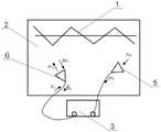
图1是本发明中的电磁混响室测试系统实施例之一的结构示意图;Fig. 1 is the structural representation of one of embodiment of electromagnetic reverberation chamber test system among the present invention;
图2是本发明中的电磁混响室测试系统实施例之二的结构示意图;Fig. 2 is the structural representation of the second embodiment of the electromagnetic reverberation chamber test system in the present invention;
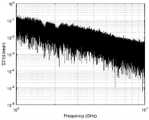
图3是图1中的单天线接收到某一边界条件下的S11参数图;Fig. 3 is the S11 parameter diagram under a certain boundary condition received by the single antenna in Fig. 1;
图4是图2中的双天线接收到某一边界条件下的S11参数图;Fig. 4 is the S11 parameter diagram under a certain boundary condition received by the dual antenna in Fig. 2;
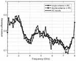
图5是本发明用于单天线和双天线法分别测得的天线效率与电波暗室中测试结果对比图;Fig. 5 is the antenna efficiency that the present invention is used for single antenna and double antenna method to measure respectively and the test result comparison chart in the anechoic chamber;
图中:1-搅拌器;2-混响室;3-矢量网络分析仪;4-第一待测天线;5-接收天线;6-发射天线。In the figure: 1-stirrer; 2-reverberation chamber; 3-vector network analyzer; 4-first antenna to be tested; 5-receiving antenna; 6-transmitting antenna.
具体实施方式detailed description
下面结合附图和实施例对本发明的技术方案作进一步详细说明。The technical solution of the present invention will be described in further detail below in conjunction with the accompanying drawings and embodiments.
实施例1Example 1
一种基于混响室的天线效率测试方法,其为单天线法,包括以下步骤:A method for testing antenna efficiency based on a reverberation chamber, which is a single-antenna method, comprising the following steps:
S1、构建电磁混响室测试系统,如图1所示,测试系统由第一待测天线4、矢量网络分析仪3组成,矢量网络分析仪的测试频率为1GHz-10GHz,为保证时域信号的准确性,频域采样点数为100001,独立搅拌位置数为20个,搅拌器1工作于步进搅拌状态,步进角度为18°;待测天线置于混响室2内部,矢量网络分析仪设置在混响室外部,矢量网络分析仪与待测天线通过射频线连接;无需提前对混响室测试区域进行均匀性校准,仅需要提前对混响室的品质因数或时间常数进行测试,此测试方法为现有技术,故不再赘述;S1, build electromagnetic reverberation chamber test system, as shown in Figure 1, test system is made up of the
S2、定义P1、P2、PTx、PRf分别为注入待测天线端口的能量、待测天线端口的反射能量、辐射入混响室的能量和反射进入待测天线的能量,得到上述各能量之间具有以下关系:S2. Define P1 , P2 , PTx , andPRf as the energy injected into the antenna port to be tested, the reflected energy at the antenna port to be tested, the energy radiated into the reverberation chamber, and the energy reflected into the antenna to be tested, respectively, and the above-mentioned The energies have the following relationship:

其中,

式中,<·>表示对所有独立搅拌位置求平均;In the formula, <·> represents the average of all independent stirring positions;
S3、根据理想混响室基本原理,<P2>/P1=<|S11,stirred|2>;对式(2)进行变形,得到:S3. According to the basic principle of the ideal reverberation chamber, <P2 >/P1 =<|S11, stirred |2 >; transform the formula (2) to get:

根据混响室内基本关系,<PRf>=2<PRx>,

式中,Q为混响室的品质因数,V为混响室的有效体积,λ为混响室的工作频率波长,S11,stirred为混响室内搅拌分量;根据混响室内品质因数和时间常数的关系,式(4)表示为:In the formula, Q is the quality factor of the reverberation chamber, V is the effective volume of the reverberation chamber, λ is the operating frequency wavelength of the reverberation chamber, S11, stirred is the stirring component of the reverberation chamber; according to the reverberation chamber quality factor and time The relationship between constants, formula (4) is expressed as:

式中,ω为混响室的工作频率,τRC为混响室的时间常数;In the formula, ω is the operating frequency of the reverberation room, and τRC is the time constant of the reverberation room;
S4、由式(5)得出的是天线总辐射效率,包含了天线端口失配的影响;为消除天线端口失配的影响,对式(5)中的混响室内搅拌分量进行修正,得到:S4. The total radiation efficiency of the antenna obtained from formula (5) includes the influence of antenna port mismatch; in order to eliminate the influence of antenna port mismatch, the stirring component in the reverberation chamber in formula (5) is corrected to obtain :

式中,S11为接收到的S参数;第一待测天线接收到某一边界条件下的S11参数曲线图,记录20个独立搅拌位置数下的20组S参数,并进行相应处理,如图3所示;In the formula,S11 is the received S parameter; the first antenna to be tested receives the S11 parameter graph under a certain boundary condition, records 20 sets of S parameters under 20 independent stirring positions, and performs corresponding processing, such as As shown in Figure 3;
S5、结合式(4)、式(6),得到被测天线的辐射效率为:S5. Combining formula (4) and formula (6), the radiation efficiency of the antenna under test is obtained as:

再结合式(5),式(7)表示为:Combined with formula (5), formula (7) is expressed as:

实施例2Example 2
一种基于混响室的天线效率测试方法,其为双天线法,包括以下步骤:A kind of antenna efficiency testing method based on reverberation chamber, it is double antenna method, comprises the following steps:
S1、构建电磁混响室测试系统,如图2所示,测试系统由第二待测天线、矢量网络分析仪3组成,矢量网络分析仪的测试频率为1GHz-10GHz,为保证时域信号的准确性,频域采样点数为100001,独立搅拌位置数为20个,搅拌器1工作于步进搅拌状态,步进角度为18°;第二待测天线置于混响室内部,第二待测天线包括发射天线6和接收天线5,矢量网络分析仪设置在混响室2外部,矢量网络分析仪与待测天线通过射频线连接;无需提前对混响室测试区域进行均匀性校准,仅需要提前对混响室的品质因数或时间常数进行测试;S1, build electromagnetic reverberation chamber test system, as shown in Figure 2, test system is made up of the second antenna to be tested,
S2、定义P1、P2、PTx、PRf分别为注入待测天线端口的能量、待测天线端口的反射能量、辐射入混响室的能量和反射进入待测天线的能量,得到上述各能量之间具有以下关系:S2. Define P1 , P2 , PTx , andPRf as the energy injected into the antenna port to be tested, the reflected energy at the antenna port to be tested, the energy radiated into the reverberation chamber, and the energy reflected into the antenna to be tested, respectively, and the above-mentioned The energies have the following relationship:

其中,

式中,<·>表示对所有独立搅拌位置求平均;In the formula, <·> represents the average of all independent stirring positions;
S3、根据理想混响室基本原理,<P2>/P1=<|S11,stirred|2>;对式(2)进行变形,得到:S3. According to the basic principle of the ideal reverberation chamber, <P2 >/P1 =<|S11, stirred |2 >; transform the formula (2) to get:

在非理想混响室条件下,存在以下关系为:Under non-ideal reverberation room conditions, the following relationship exists:

式中,eb为后向散射常数;In the formula, eb is the backscattering constant;

式中,S11,stirred为混响室内S11的搅拌分量,S22,stirred为混响室内S22的搅拌分量,S21,stirred为混响室内S21的搅拌分量,<·>表示对所有独立搅拌位置求平均;双天线接收到某一边界条件下的S21参数曲线图,记录20个独立搅拌位置数下的20组S参数,并进行相应处理,如图4所示;In the formula, S11, stirred is the stirring component of S11 in the reverberation chamber, S22, stirred is the stirring component of S22 in the reverberation chamber, S21, stirred is the stirring component of S21 in the reverberation chamber, <·> represents the All independent stirring positions are averaged; the dual antenna receives the S21 parameter curve under a certain boundary condition, records 20 sets of S parameters under 20 independent stirring positions, and performs corresponding processing, as shown in Figure 4;
基于后向散射常数的概念,得到式(11)中的双天线的总天线效率:Based on the concept of the backscattering constant, the total antenna efficiency of the dual antenna in Equation (11) is obtained:

式中,

S4、对式(11)中的混响室内搅拌分量S11,stirred、S22,stirred分别进行修正,得到:S4. The stirring components S11, stirred , S22, stirred in the reverberation chamber in the formula (11) are respectively corrected to obtain:


式中,S11为实测S11参数;S22为实测S22参数;In the formula,S11 is the measured S11 parameter;S22 is the measured S22 parameter;
S5、结合式(11)、式(12)、式(13),得到被测双天线的辐射效率:S5, combining formula (11), formula (12), formula (13), obtain the radiation efficiency of measured dual antenna:

式中,

如图5所示,单天线法(single antenna in RC)和双天线法(double antenna inRC)的天线效率测试结果与电波暗室中测试结果(AC results)对比,获知测试结果的一致性是很好的,表明本发明的测试方法切实可行,能够准确测得未知天线的天线效率。As shown in Figure 5, the antenna efficiency test results of the single antenna in RC and double antenna in RC are compared with the test results in the anechoic chamber (AC results), and the consistency of the test results is very good. It shows that the test method of the present invention is feasible and can accurately measure the antenna efficiency of an unknown antenna.
以上所述仅为本发明的较佳实施例,而非对本发明的限制,在不脱离本发明的精神和范围的情况下,凡依本发明申请专利范围所作的均等变化与修饰,皆应属本发明的专利保护范围之内。The above descriptions are only preferred embodiments of the present invention, rather than limitations of the present invention. Without departing from the spirit and scope of the present invention, all equivalent changes and modifications made according to the scope of the patent application for the present invention shall belong to Within the scope of patent protection of the present invention.
Claims (2)


Priority Applications (1)
| Application Number | Priority Date | Filing Date | Title |
|---|---|---|---|
| CN202211166404.9ACN115542026A (en) | 2022-09-23 | 2022-09-23 | An Antenna Efficiency Test Method Based on Reverberation Chamber |
Applications Claiming Priority (1)
| Application Number | Priority Date | Filing Date | Title |
|---|---|---|---|
| CN202211166404.9ACN115542026A (en) | 2022-09-23 | 2022-09-23 | An Antenna Efficiency Test Method Based on Reverberation Chamber |
Publications (1)
| Publication Number | Publication Date |
|---|---|
| CN115542026Atrue CN115542026A (en) | 2022-12-30 |
Family
ID=84728800
Family Applications (1)
| Application Number | Title | Priority Date | Filing Date |
|---|---|---|---|
| CN202211166404.9APendingCN115542026A (en) | 2022-09-23 | 2022-09-23 | An Antenna Efficiency Test Method Based on Reverberation Chamber |
Country Status (1)
| Country | Link |
|---|---|
| CN (1) | CN115542026A (en) |
Cited By (1)
| Publication number | Priority date | Publication date | Assignee | Title |
|---|---|---|---|---|
| CN117590090A (en)* | 2024-01-18 | 2024-02-23 | 中国计量科学研究院 | A device, method and equipment for quickly confirming the field uniformity of an electromagnetic reverberation room |
Citations (3)
| Publication number | Priority date | Publication date | Assignee | Title |
|---|---|---|---|---|
| CN111337758A (en)* | 2020-03-11 | 2020-06-26 | 南京航空航天大学 | An antenna radiation efficiency measurement method based on reverberation chamber |
| CN112415280A (en)* | 2020-11-26 | 2021-02-26 | 上海卫星装备研究所 | Spacecraft radiation emission test system and method based on electric wave reverberation chamber |
| CN114527345A (en)* | 2022-02-28 | 2022-05-24 | 中国人民解放军63892部队 | Electromagnetic reverberation chamber-based loading absorption cross section rapid evaluation method |
- 2022
- 2022-09-23CNCN202211166404.9Apatent/CN115542026A/enactivePending
Patent Citations (3)
| Publication number | Priority date | Publication date | Assignee | Title |
|---|---|---|---|---|
| CN111337758A (en)* | 2020-03-11 | 2020-06-26 | 南京航空航天大学 | An antenna radiation efficiency measurement method based on reverberation chamber |
| CN112415280A (en)* | 2020-11-26 | 2021-02-26 | 上海卫星装备研究所 | Spacecraft radiation emission test system and method based on electric wave reverberation chamber |
| CN114527345A (en)* | 2022-02-28 | 2022-05-24 | 中国人民解放军63892部队 | Electromagnetic reverberation chamber-based loading absorption cross section rapid evaluation method |
Non-Patent Citations (1)
| Title |
|---|
| CHRISTOPHER L. HOLLOWAY 等: "Reverberation Chamber Techniques for Determining the Radiation and Total Efficiency of Antennas", IEEE TRANSACTIONS ON ANTENNAS AND PROPAGATION, vol. 60, no. 4, 31 March 2012 (2012-03-31), pages 1758 - 1770, XP011440878, DOI: 10.1109/TAP.2012.2186263* |
Cited By (2)
| Publication number | Priority date | Publication date | Assignee | Title |
|---|---|---|---|---|
| CN117590090A (en)* | 2024-01-18 | 2024-02-23 | 中国计量科学研究院 | A device, method and equipment for quickly confirming the field uniformity of an electromagnetic reverberation room |
| CN117590090B (en)* | 2024-01-18 | 2024-04-02 | 中国计量科学研究院 | A device, method and equipment for quickly confirming the field uniformity of an electromagnetic reverberation room |
Similar Documents
| Publication | Publication Date | Title |
|---|---|---|
| CN106443208B (en) | Shield effectiveness measurement method, measuring system and the calibration system of shielding material | |
| US9699678B2 (en) | Plane wave generation within a small volume of space for evaluation of wireless devices | |
| CN109884407B (en) | Electromagnetic shielding effectiveness measuring system and measuring method | |
| CN115453214A (en) | Measuring device and measuring method for internal field active interference scattering characteristics | |
| CN117590092B (en) | Antenna radiation efficiency measuring method and system and electronic equipment | |
| CN109884606B (en) | RCS measuring device based on single-antenna radar scattering cross section and performance analysis method | |
| Barowski et al. | Millimeter wave material characterization using FMCW-transceivers | |
| CN115542026A (en) | An Antenna Efficiency Test Method Based on Reverberation Chamber | |
| CN117890683B (en) | Active wireless communication device total radiated power measurement method, system and electronic device | |
| CN109884406B (en) | High-frequency electromagnetic shielding effectiveness measuring system, measuring method and device | |
| Chen et al. | Limitations of the Free Space VSWR Measurements for chamber validations | |
| CN114264888B (en) | SAR load satellite pulse electromagnetic leakage testing method | |
| Sivakumar et al. | A Free-Space Measurement System for Microwave Materials at Kuband | |
| Constantin et al. | A single-antenna calibration method | |
| Zheng et al. | Testing Method of a Millimeter-Wave/THz Far-Field Antenna Measurement Setup | |
| CN117008071B (en) | A chirp MIMO radar channel calibration method and related equipment | |
| CN117375736B (en) | Differential mode injection test method and system for electromagnetic compatibility sensitivity test | |
| Wang et al. | MIMO Performance and Uncertainty Analysis in a Reverberation Chamber With Phase Stirring | |
| Xu et al. | Measuring the total radiated energy of transient signals in a reverberation chamber | |
| Gu et al. | Development of a TEM cell with 2 m in height | |
| CN119087372A (en) | Distance Accuracy Calibration Method for Indoor Radio Frequency Simulation System Based on Electrical Delay Technology | |
| Jiang | Total Radiated Power and Antenna Radiation Efficiency Measurements Using a TEM Cell | |
| Smirnov | Absolute method of RCS measurements and technical means for its implementation | |
| Vie et al. | Investigation of the performance of the GTEM 1750 from 0.08 GHz to 6 GHz | |
| Farid et al. | A Comparative Study on Spatial Uniformity Metrics for Reverberation Chambers |
Legal Events
| Date | Code | Title | Description |
|---|---|---|---|
| PB01 | Publication | ||
| PB01 | Publication | ||
| SE01 | Entry into force of request for substantive examination | ||
| SE01 | Entry into force of request for substantive examination |