CN115539193A - Pipeline exhaust system, thermal management system and vehicle - Google Patents
Pipeline exhaust system, thermal management system and vehicleDownload PDFInfo
- Publication number
- CN115539193A CN115539193ACN202110735689.2ACN202110735689ACN115539193ACN 115539193 ACN115539193 ACN 115539193ACN 202110735689 ACN202110735689 ACN 202110735689ACN 115539193 ACN115539193 ACN 115539193A
- Authority
- CN
- China
- Prior art keywords
- preset
- pressure
- exhaust
- pipeline
- condition
- Prior art date
- Legal status (The legal status is an assumption and is not a legal conclusion. Google has not performed a legal analysis and makes no representation as to the accuracy of the status listed.)
- Granted
Links
Images


Classifications
- F—MECHANICAL ENGINEERING; LIGHTING; HEATING; WEAPONS; BLASTING
- F01—MACHINES OR ENGINES IN GENERAL; ENGINE PLANTS IN GENERAL; STEAM ENGINES
- F01P—COOLING OF MACHINES OR ENGINES IN GENERAL; COOLING OF INTERNAL-COMBUSTION ENGINES
- F01P11/00—Component parts, details, or accessories not provided for in, or of interest apart from, groups F01P1/00 - F01P9/00
- F01P11/02—Liquid-coolant filling, overflow, venting, or draining devices
- F01P11/0285—Venting devices
- F—MECHANICAL ENGINEERING; LIGHTING; HEATING; WEAPONS; BLASTING
- F01—MACHINES OR ENGINES IN GENERAL; ENGINE PLANTS IN GENERAL; STEAM ENGINES
- F01P—COOLING OF MACHINES OR ENGINES IN GENERAL; COOLING OF INTERNAL-COMBUSTION ENGINES
- F01P11/00—Component parts, details, or accessories not provided for in, or of interest apart from, groups F01P1/00 - F01P9/00
- F01P11/04—Arrangements of liquid pipes or hoses
- F—MECHANICAL ENGINEERING; LIGHTING; HEATING; WEAPONS; BLASTING
- F01—MACHINES OR ENGINES IN GENERAL; ENGINE PLANTS IN GENERAL; STEAM ENGINES
- F01P—COOLING OF MACHINES OR ENGINES IN GENERAL; COOLING OF INTERNAL-COMBUSTION ENGINES
- F01P11/00—Component parts, details, or accessories not provided for in, or of interest apart from, groups F01P1/00 - F01P9/00
- F01P11/14—Indicating devices; Other safety devices
- F—MECHANICAL ENGINEERING; LIGHTING; HEATING; WEAPONS; BLASTING
- F01—MACHINES OR ENGINES IN GENERAL; ENGINE PLANTS IN GENERAL; STEAM ENGINES
- F01P—COOLING OF MACHINES OR ENGINES IN GENERAL; COOLING OF INTERNAL-COMBUSTION ENGINES
- F01P2050/00—Applications
- F01P2050/22—Motor-cars
Landscapes
- Engineering & Computer Science (AREA)
- Chemical & Material Sciences (AREA)
- Combustion & Propulsion (AREA)
- Mechanical Engineering (AREA)
- General Engineering & Computer Science (AREA)
- Pipeline Systems (AREA)
Abstract
Description
Translated fromChinese技术领域technical field
本公开涉及管路技术领域,具体地,涉及一种管路排气系统、热管理系统及车辆。The present disclosure relates to the technical field of pipelines, in particular, to a pipeline exhaust system, a heat management system and a vehicle.
背景技术Background technique
现阶段,大多数的管路系统(例如,动力车辆的热管理管路系统)无法实现有效排气,尤其是在更换循环液时,无法进行有效的排气,导致循环液无法灌满。由于管路系统的管道复杂,尤其在拐角点和弯曲管道顶部处都容易出现气泡,而这些气泡多了会严重影响到管路性能。现阶段,主要通过以下两种方式实现管路系统排气:(1)使用外部真空加注机,通过抽离管路系统中的气体,造成内部气压小,在灌注循环液时,易于把管道灌满循环液,规避了排气问题;(2)外接排气工装,通过串联一个水箱和水泵的方式把气体排出。但这两种方式均存在无法实现自动排气、外接设备成本高昂、维修操作不便等问题。At present, most pipeline systems (for example, thermal management pipeline systems of power vehicles) cannot achieve effective exhaust, especially when changing the circulating fluid, which leads to the inability to fill the circulating fluid. Due to the complexity of the pipeline system, air bubbles are prone to appear especially at the corners and the top of the curved pipe, and these bubbles will seriously affect the performance of the pipeline. At this stage, the exhaust of the pipeline system is mainly achieved through the following two methods: (1) Use an external vacuum filling machine to remove the gas in the pipeline system, resulting in low internal air pressure. It is filled with circulating fluid to avoid the exhaust problem; (2) External exhaust tooling is used to discharge the gas by connecting a water tank and a water pump in series. However, these two methods have problems such as the inability to realize automatic exhaust, the high cost of external equipment, and the inconvenience of maintenance and operation.
发明内容Contents of the invention
为了克服相关技术中存在的问题,本公开提供一种管路排气系统、热管理系统及车辆。In order to overcome the problems in the related art, the present disclosure provides a pipeline exhaust system, a heat management system and a vehicle.
为了实现上述目的,第一方面,本公开提供一种管路排气系统,包括:控制模块、排气装置以及压力调节装置,所述压力调节装置通过管路与所述排气装置连通;In order to achieve the above object, in the first aspect, the present disclosure provides a pipeline exhaust system, including: a control module, an exhaust device, and a pressure regulating device, and the pressure regulating device communicates with the exhaust device through a pipeline;
所述控制模块用于检测所述管路是否满足预设排气条件,并在所述管路满足所述预设排气条件时,发送所述预设排气条件对应的预设排气信号至所述压力调节装置;The control module is used to detect whether the pipeline meets the preset exhaust condition, and when the pipeline meets the preset exhaust condition, send a preset exhaust signal corresponding to the preset exhaust condition to said pressure regulating device;
所述压力调节装置用于响应所述预设排气信号,并按照所述预设排气信号对应的预设规律调整所述管路内的压力,以使所述管路内气体经所述排气装置排出。The pressure regulating device is used to respond to the preset exhaust signal, and adjust the pressure in the pipeline according to the preset law corresponding to the preset exhaust signal, so that the gas in the pipeline passes through the Exhaust exhaust.
可选地,所述控制模块用于检测所述管路是否满足预设排气条件,并在所述管路满足所述预设排气条件时,发送相应的预设排气信号至所述压力调节装置;Optionally, the control module is used to detect whether the pipeline meets the preset exhaust condition, and when the pipeline meets the preset exhaust condition, send a corresponding preset exhaust signal to the pressure regulating device;
所述压力调节装置用于响应所述预设排气信号,并按照所述预设排气信号对应的预设规律调整所述管路内的压力,以使所述管路内气体经所述排气装置排出;The pressure regulating device is used to respond to the preset exhaust signal, and adjust the pressure in the pipeline according to the preset law corresponding to the preset exhaust signal, so that the gas in the pipeline passes through the Exhaust discharge;
具体包括:Specifically include:
所述控制模块用于检测所述管路是否满足初始排气条件,并在所述管路满足所述初始排气条件时,发送第一预设排气信号至所述压力调节装置;The control module is used to detect whether the pipeline meets the initial exhaust condition, and when the pipeline meets the initial exhaust condition, send a first preset exhaust signal to the pressure regulating device;
所述压力调节装置用于接收所述第一预设排气信号,并基于所述第一预设排气信号使所述压力调节装置处在第一预设状态;The pressure regulating device is configured to receive the first preset exhaust signal, and make the pressure regulating device in a first preset state based on the first preset exhaust signal;
所述控制模块用于在所述压力调节装置处在所述第一预设状态,并检测到所述管路满足第一预设条件时,发送第二预设排气信号至所述压力调节装置;The control module is configured to send a second preset exhaust signal to the pressure regulator when the pressure regulator is in the first preset state and detects that the pipeline satisfies a first preset condition device;
所述压力调节装置用于接收所述第二预设排气信号,并基于所述第二排气信号使所述压力调节装置至第二预设状态;The pressure regulating device is configured to receive the second preset exhaust signal, and make the pressure regulating device to a second preset state based on the second exhaust signal;
所述控制模块用于在所述压力调节装置至所述第二预设状态,并检测到所述管路满足第二预设条件时,发送第三排气信号至所述压力调节装置;The control module is configured to send a third exhaust signal to the pressure regulating device when the pressure regulating device reaches the second preset state and detects that the pipeline satisfies a second preset condition;
所述压力调节装置用于接收所述第三排气信号,并基于所述第三排气信号使所述压力调节装置至第三预设状态;The pressure regulating device is configured to receive the third exhaust signal, and make the pressure regulating device to a third preset state based on the third exhaust signal;
所述控制模块用于在所述压力调节装置至第三预设状态,并检测到所述管路满足第三预设条件时,判断所述管路是否满足所述初始排气条件,The control module is used to determine whether the pipeline satisfies the initial exhaust condition when the pressure regulating device reaches a third preset state and detects that the pipeline satisfies a third preset condition,
若所述控制模块检测到所述管路满足所述初始排气条件,则发送所述第一排气信号至所述压力调节装置;If the control module detects that the pipeline satisfies the initial exhaust condition, sending the first exhaust signal to the pressure regulating device;
若所述控制模块检测到所述管路不满足所述初始排气条件,则发送第四排气信号至所述压力调节装置;If the control module detects that the pipeline does not satisfy the initial exhaust condition, sending a fourth exhaust signal to the pressure regulating device;
所述压力调节装置用于接收所述第四排气信号,使所述压力调节装置处于初始状态。The pressure regulating device is used to receive the fourth exhaust signal, so that the pressure regulating device is in an initial state.
可选地,所述压力调节装置包括通过第一管路连接的水泵和调节阀,其中,所述调节阀、所述排气装置以及所述水泵通过第二管路依次连接;Optionally, the pressure regulating device includes a water pump and a regulating valve connected through a first pipeline, wherein the regulating valve, the exhaust device and the water pump are sequentially connected through a second pipeline;
所述第一预设状态为所述调节阀关闭;The first preset state is that the regulating valve is closed;
所述第二预设状态为所述调节阀的开度为第一预设开度阈值,其中,所述第一预设开度阈值小于或等于100%;The second preset state is that the opening of the regulating valve is a first preset opening threshold, wherein the first preset opening threshold is less than or equal to 100%;
所述第三预设状态为所述调节阀的开度为第二预设开度阈值,其中,所述第二预设开度阈值大于0%、且小于所述第一预设开度阈值;The third preset state is that the opening of the regulating valve is a second preset opening threshold, wherein the second preset opening threshold is greater than 0% and smaller than the first preset opening threshold ;
所述初始状态为所述调节阀的开度为100%。The initial state is that the opening of the regulating valve is 100%.
可选地,所述第一预设排气条件包括以下中的任一者:Optionally, the first preset exhaust condition includes any of the following:
所述调节阀处于关闭状态的持续时长达到第一预设时长;The duration of the regulating valve being in the closed state reaches a first preset duration;
所述第一管路内的压力达到第一预设压力;The pressure in the first pipeline reaches a first preset pressure;
所述第二预设排气条件包括以下中的任一者:The second preset exhaust condition includes any of the following:
所述调节阀的开度处于所述第一预设开度阈值状态的持续时长达到第二预设时长;The duration of the opening of the regulating valve in the first preset opening threshold state reaches a second preset duration;
所述第一管路内的压力降到第二预设压力;The pressure in the first pipeline drops to a second preset pressure;
所述第三预设排气条件包括以下中的任一者:The third preset exhaust condition includes any of the following:
所述调节阀的开度处于所述第二预设开度阈值状态的持续时长达到第三预设时长;The duration of the opening of the regulating valve being in the second preset opening threshold state reaches a third preset duration;
所述第二管路内的压力降到第三预设压力;The pressure in the second pipeline drops to a third preset pressure;
其中,所述第二预设压力、所述第三预设压力均小于所述第一预设压力。Wherein, both the second preset pressure and the third preset pressure are smaller than the first preset pressure.
可选地,所述压力调节装置包括水泵,其中,所述水泵的出水口通过第三管路与所述排气装置连接,所述水泵的进水口通过第四管路与所述排气装置连接,所述水泵为压力可调节水泵;Optionally, the pressure regulating device includes a water pump, wherein the water outlet of the water pump is connected to the exhaust device through a third pipeline, and the water inlet of the water pump is connected to the exhaust device through a fourth pipeline. connected, the water pump is a pressure-adjustable water pump;
所述第一预设状态为所述水泵的压力为第四预设压力;The first preset state is that the pressure of the water pump is a fourth preset pressure;
所述第二预设状态为所述水泵的压力为第五预设压力;The second preset state is that the pressure of the water pump is the fifth preset pressure;
所述第三预设状态为所述水泵的压力为第六预设压力,其中,所述第五预设压力、所述第六预设压力、所述第四预设压力依次增大;The third preset state is that the pressure of the water pump is the sixth preset pressure, wherein the fifth preset pressure, the sixth preset pressure, and the fourth preset pressure increase sequentially;
所述初始状态为水泵的压力为初始预设压力,其中,所述初始预设压力在所述第六预设压力和所述第四预设压力之间。The initial state is that the pressure of the water pump is an initial preset pressure, wherein the initial preset pressure is between the sixth preset pressure and the fourth preset pressure.
可选地,所述第一预设排气条件包括以下中的任一者:Optionally, the first preset exhaust condition includes any of the following:
所述水泵的压力处于所述第四预设压力的持续时长达到第四预设时长;The duration of the pressure of the water pump being at the fourth preset pressure reaches a fourth preset duration;
第三管路内的压力增到第七预设压力;The pressure in the third pipeline is increased to the seventh preset pressure;
所述第二预设排气条件包括以下中的任一者:The second preset exhaust condition includes any of the following:
所述水泵的压力处于所述第五预设压力的持续时长达到第五预设时长;The duration of the pressure of the water pump at the fifth preset pressure reaches the fifth preset duration;
所述第三管路内的压力降到第八预设压力;The pressure in the third pipeline drops to an eighth preset pressure;
所述第三预设排气条件包括以下中的任一者:The third preset exhaust condition includes any of the following:
所述水泵的压力处于所述第六预设压力的持续时长达到第六预设时长;The duration of the pressure of the water pump being at the sixth preset pressure reaches a sixth preset duration;
所述第四管路内的压力降到第九预设压力;The pressure in the fourth pipeline drops to a ninth preset pressure;
其中,所述第七预设压力、所述第九预设压力、所述第八预设压力依次减小。Wherein, the seventh preset pressure, the ninth preset pressure, and the eighth preset pressure decrease sequentially.
可选地,所述排气装置为水箱,所述水箱包括进气口和排气口,所述进气口与所述管路连通,所述排气口连通外部环境;Optionally, the exhaust device is a water tank, the water tank includes an air inlet and an air outlet, the air inlet communicates with the pipeline, and the air outlet communicates with the external environment;
所述排气系统还包括液位传感器,设置在所述水箱内,用于实时检测所述水箱的液位;The exhaust system also includes a liquid level sensor arranged in the water tank for real-time detection of the liquid level of the water tank;
所述控制模块,与所述液位传感器连接,还用于通过所述液位传感器实时获取所述水箱的液位;The control module is connected to the liquid level sensor, and is also used to obtain the liquid level of the water tank in real time through the liquid level sensor;
所述控制模块用于检测所述管路是否满足初始排气条件,包括:The control module is used to detect whether the pipeline meets the initial exhaust conditions, including:
所述控制模块用于在所述水箱的液位在第七预设时长内的变化量大于预设液位阈值时,确定所述管路满足初始排气条件。The control module is configured to determine that the pipeline satisfies the initial exhaust condition when the variation of the liquid level of the water tank within the seventh preset time period is greater than a preset liquid level threshold.
可选地,所述排气系统还包括流量传感器,用于实时检测所述管路的流量;Optionally, the exhaust system further includes a flow sensor for detecting the flow of the pipeline in real time;
所述控制模块还用于通过所述流量传感器获取所述管路的流量,并判断所述流量是否超出预设流量范围,并在所述流量超出预设流量范围时,发送异常信号至所述压力调节装置;The control module is also used to obtain the flow rate of the pipeline through the flow sensor, and judge whether the flow rate exceeds a preset flow range, and send an abnormal signal to the pressure regulating device;
所述压力调节装置还用于接收所述异常信号,并停止工作和/或发出异常告警。The pressure regulating device is also used to receive the abnormal signal, stop working and/or issue an abnormal alarm.
第二方面,本公开提供一种热管理系统,包括:In a second aspect, the present disclosure provides a thermal management system, including:
如本公开第一方面提供的所述管路排气系统、冷却装置、加热装置以及冷却负载。The pipeline exhaust system, cooling device, heating device and cooling load provided in the first aspect of the present disclosure.
第三方面,本公开提供一种车辆,包括如本公开第二方面提供的所述热管理系统。In a third aspect, the present disclosure provides a vehicle, including the thermal management system as provided in the second aspect of the present disclosure.
在上述技术方案中,管路排气系统包括控制模块、排气装置以及压力调节装置,其中,压力调节装置通过管路与排气装置连通;控制模块用于检测管路是否满足预设排气条件,并在管路满足预设排气条件时,发送预设排气条件对应的预设排气信号至压力调节装置;压力调节装置用于响应预设排气信号,并按照预设排气信号对应的预设规律调整管路内的压力,以使管路内气体经排气装置排出。这样,通过调整管路内的压力即可实现管路排气系统自动排气,并且,用于调整管路内压力的压力调节装置和排气装置均属于管路排气系统的内置设备,这样,就无需外接排气设备,避免了维修操作不便等问题。In the above technical solution, the pipeline exhaust system includes a control module, an exhaust device and a pressure regulating device, wherein the pressure regulating device communicates with the exhaust device through a pipeline; the control module is used to detect whether the pipeline meets the preset exhaust requirements. condition, and when the pipeline meets the preset exhaust condition, send the preset exhaust signal corresponding to the preset exhaust condition to the pressure regulating device; the pressure regulating device is used to respond to the preset exhaust signal and exhaust according to the preset The preset law corresponding to the signal adjusts the pressure in the pipeline so that the gas in the pipeline is discharged through the exhaust device. In this way, the automatic exhaust of the pipeline exhaust system can be realized by adjusting the pressure in the pipeline, and the pressure regulating device and exhaust device used to adjust the pressure in the pipeline belong to the built-in equipment of the pipeline exhaust system, so , there is no need for external exhaust equipment, which avoids problems such as inconvenient maintenance and operation.
本公开的其他特征和优点将在随后的具体实施方式部分予以详细说明。Other features and advantages of the present disclosure will be described in detail in the detailed description that follows.
附图说明Description of drawings
附图是用来提供对本公开的进一步理解,并且构成说明书的一部分,与下面的具体实施方式一起用于解释本公开,但并不构成对本公开的限制。在附图中:The accompanying drawings are used to provide a further understanding of the present disclosure, and constitute a part of the description, together with the following specific embodiments, are used to explain the present disclosure, but do not constitute a limitation to the present disclosure. In the attached picture:
图1是根据一示例性实施例示出的一种管路排气系统的框图。Fig. 1 is a block diagram of a pipeline exhaust system according to an exemplary embodiment.
图2是根据另一示例性实施例示出的一种管路排气系统的框图。Fig. 2 is a block diagram of a pipeline exhaust system according to another exemplary embodiment.
图3A是根据另一示例性实施例示出的一种管路排气系统的框图。Fig. 3A is a block diagram of a pipeline exhaust system according to another exemplary embodiment.
图3B是根据另一示例性实施例示出的一种管路排气系统的框图。Fig. 3B is a block diagram of a pipeline exhaust system according to another exemplary embodiment.
图3C是根据另一示例性实施例示出的一种管路排气系统的框图。Fig. 3C is a block diagram of a pipeline exhaust system according to another exemplary embodiment.
图4是根据另一示例性实施例示出的一种管路排气系统的框图。Fig. 4 is a block diagram of a pipeline exhaust system according to another exemplary embodiment.
图5A是根据另一示例性实施例示出的一种管路排气系统的框图。Fig. 5A is a block diagram of a pipeline exhaust system according to another exemplary embodiment.
图5B是根据另一示例性实施例示出的一种管路排气系统的框图。Fig. 5B is a block diagram of a pipeline exhaust system according to another exemplary embodiment.
图5C是根据另一示例性实施例示出的一种管路排气系统的框图。Fig. 5C is a block diagram of a pipeline exhaust system according to another exemplary embodiment.
图6A是根据另一示例性实施例示出的一种管路排气系统的框图。Fig. 6A is a block diagram of a pipeline exhaust system according to another exemplary embodiment.
图6B是根据另一示例性实施例示出的一种管路排气系统的框图。Fig. 6B is a block diagram of a pipeline exhaust system according to another exemplary embodiment.
图7A是根据另一示例性实施例示出的一种管路排气系统的框图。Fig. 7A is a block diagram of a pipeline exhaust system according to another exemplary embodiment.
图7B是根据另一示例性实施例示出的一种管路排气系统的框图。Fig. 7B is a block diagram of a pipeline exhaust system according to another exemplary embodiment.
附图标记说明Explanation of reference signs
1 控制模块 2 冷却装置1
3 压力调节装置 4 第一压力传感器3 Pressure regulator 4 First pressure sensor
5 第二压力传感器 6 第三压力传感器5 2nd pressure sensor 6 3rd pressure sensor
7 第四压力传感器 8 液位传感器7 Fourth pressure sensor 8 Liquid level sensor
9 流量传感器 31 水泵9
32 调节阀32 regulator valve
具体实施方式detailed description
以下结合附图对本公开的具体实施方式进行详细说明。应当理解的是,此处所描述的具体实施方式仅用于说明和解释本公开,并不用于限制本公开。Specific embodiments of the present disclosure will be described in detail below in conjunction with the accompanying drawings. It should be understood that the specific embodiments described here are only used to illustrate and explain the present disclosure, and are not intended to limit the present disclosure.
图1是根据一示例性实施例示出的一种管路排气系统的框图。如图1所示,该管路排气系统包括控制模块1、排气装置2以及压力调节装置3,压力调节装置3通过管路与排气装置2连通,并且,压力调节装置3与控制模块1连接。Fig. 1 is a block diagram of a pipeline exhaust system according to an exemplary embodiment. As shown in Figure 1, the pipeline exhaust system includes a
其中,控制模块1用于检测管路是否满足预设排气条件,并在管路满足预设排气条件时,发送预设排气条件对应的预设排气信号至压力调节装置3;压力调节装置3用于响应预设排气信号,并按照预设排气信号对应的预设规律调整管路内的压力,以使管路内气体经排气装置2排出。Among them, the
在本公开中,控制模块1在管路处于正常循环状态(即不进行排气)时,实时检测管路是否满足预设排气条件;在确定满足预设排气条件时,进入排气流程,即发送预设排气条件对应的预设排气信号至压力调节装置3,以通过压力调节装置3调整管路内的压力,使得管路内气体经排气装置2排出。在确定管路不满足预设排气条件时,则继续检测管路是否满足预设排气条件。In the present disclosure, the
在上述技术方案中,管路排气系统包括控制模块、排气装置以及压力调节装置,其中,压力调节装置通过管路与排气装置连通;控制模块用于检测管路是否满足预设排气条件,并在管路满足预设排气条件时,发送预设排气条件对应的预设排气信号至压力调节装置;压力调节装置用于响应预设排气信号,并按照预设排气信号对应的预设规律调整管路内的压力,以使管路内气体经排气装置排出。这样,通过调整管路内的压力即可实现管路排气系统自动排气,并且,用于调整管路内压力的压力调节装置和排气装置均属于管路排气系统的内置设备,这样,就无需外接排气设备,避免了维修操作不便等问题。In the above technical solution, the pipeline exhaust system includes a control module, an exhaust device and a pressure regulating device, wherein the pressure regulating device communicates with the exhaust device through a pipeline; the control module is used to detect whether the pipeline meets the preset exhaust requirements. condition, and when the pipeline meets the preset exhaust condition, send the preset exhaust signal corresponding to the preset exhaust condition to the pressure regulating device; the pressure regulating device is used to respond to the preset exhaust signal and exhaust according to the preset The preset law corresponding to the signal adjusts the pressure in the pipeline so that the gas in the pipeline is discharged through the exhaust device. In this way, the automatic exhaust of the pipeline exhaust system can be realized by adjusting the pressure in the pipeline, and the pressure regulating device and exhaust device used to adjust the pressure in the pipeline belong to the built-in equipment of the pipeline exhaust system, so , there is no need for external exhaust equipment, which avoids problems such as inconvenient maintenance and operation.
具体来说,上述管路排气系统可以利用控制模块1、排气装置2以及压力调节装置3通过以下方式来实现排气。Specifically, the above pipeline exhaust system can utilize the
控制模块1用于检测管路是否满足初始排气条件,并在管路满足初始排气条件时,发送第一预设排气信号至压力调节装置3;压力调节装置3用于接收第一预设排气信号,并基于第一预设排气信号使压力调节装置3处在第一预设状态;控制模块1用于在压力调节装置3处在第一预设状态,并检测到管路满足第一预设条件时,发送第二预设排气信号至压力调节装置3;压力调节装置3用于接收第二预设排气信号,并基于第二排气信号使压力调节装置3至第二预设状态;控制模块1用于在压力调节装置3至第二预设状态,并检测到管路满足第二预设条件时,发送第三排气信号至压力调节装置3;压力调节装置3用于接收第三排气信号,并基于第三排气信号使压力调节装置3至第三预设状态;控制模块1用于在压力调节装置3至第三预设状态,并检测到管路满足第三预设条件时,判断管路是否满足初始排气条件,若控制模块1检测到管路满足初始排气条件,则发送第一排气信号至压力调节装置3,即继续进行排气;若控制模块1检测到管路不满足初始排气条件,则退出排气流程,即发送第四排气信号至压力调节装置3;压力调节装置3用于接收第四排气信号,使压力调节装置3处于初始状态,即使得管路进入正常循环状态。The
在上述实施方式中,通过控制调节压力装置2的状态变化实现管路内压力的调整,以将管路内气体排出。In the above embodiments, the adjustment of the pressure in the pipeline is realized by controlling and adjusting the state change of the
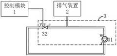
本公开中,上述压力调节装置可以具有多种结构,在一种实施方式中,如图2所示,压力调节装置3包括通过第一管路连接的水泵31和调节阀32,调节阀32、排气装置2以及水泵31通过第二管路依次连接,调节阀32与控制模块1连接。如图2所示,第一管路为水泵31的出水口至调节阀32的进水口之间的管路,也即xy段管路,第二管路为调节阀32的出水口至水泵31的进水口之间的管路,也即zw段管路。In the present disclosure, the above-mentioned pressure regulating device may have various structures. In one embodiment, as shown in FIG. The
其中,水泵31可以为压力固定的水泵(即定功率水泵),也可以是压力可调节水泵;调节阀32可以为电动调节阀、气动调节阀或其他模式的调节阀。Wherein, the
此时,第一预设状态为调节阀32关闭;第二预设状态为调节阀32的开度为第一预设开度阈值,其中,第一预设开度阈值小于或等于100%;第三预设状态为调节阀32的开度为第二预设开度阈值,其中,第二预设开度阈值大于0%、且小于第一预设开度阈值;初始状态为调节阀32的开度为100%。即管路排气系统通过以下步骤(1)~步骤(11)来实现排气:At this time, the first preset state is that the regulating
(1)控制模块1检测管路是否满足初始排气条件。(1) The
控制模块1在检测到管路满足初始排气条件时,执行以下步骤(2);若检测到管路不满足初始排气条件,则继续检测是否满足初始排气条件,即返回步骤(1)。When the
(2)控制模块1发送第一预设排气信号至调节阀32。(2) The
(3)调节阀32接收第一预设排气信号,并基于第一预设排气信号关闭。(3) The regulating
在本公开中,管路处于正常循环状态时,调节阀的开度为100%,在其满足初始排气条件时,调节阀32关闭,由于水泵31处于工作状态,因此,第一管路中循环液的液压快速增大,第二管路中循环液的液压迅速减小,导致调节阀32两端循环液的液压不一致。In this disclosure, when the pipeline is in a normal circulation state, the opening of the regulating valve is 100%. When it meets the initial exhaust condition, the regulating
(4)控制模块1检测管路是否满足第一预设条件,并在检测到管路满足第一预设条件时,发送第二预设排气信号至调节阀32。(4) The
在本公开实施例中,第一预设条件可以包括以下a、b中的任一者:In an embodiment of the present disclosure, the first preset condition may include any of the following a and b:
a、调节阀处于关闭状态的持续时长达到第一预设时长。a. The duration of the regulating valve being in the closed state reaches a first preset duration.
其中,第一预设时长可以根据第一管路的布置情况和水泵的能力确定,使得调节阀处于关闭状态期间,管路排气系统中管路内的压力始终小于管路所能承受的最大压力值。Wherein, the first preset time length can be determined according to the layout of the first pipeline and the capacity of the water pump, so that when the regulating valve is in the closed state, the pressure in the pipeline in the pipeline exhaust system is always lower than the maximum pressure that the pipeline can bear. Pressure value.
b、第一管路内的压力达到第一预设压力。b. The pressure in the first pipeline reaches the first preset pressure.
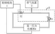
示例地,如图3A、图3C所示,管路排气系统还包括设置在水泵31与调节阀32之间的、用于检测第一管路内的压力的第一压力传感器4;控制模块1与第一压力传感器4连接,用于从第一压力传感器4获取第一管路内的压力,并在控制调节阀32关闭后,实时判定该第一管路内的压力是否达到第一预设压力(例如,15MPa)。For example, as shown in FIG. 3A and FIG. 3C , the pipeline exhaust system further includes a first pressure sensor 4 arranged between the
在调节阀32关闭后,控制模块1判断是否满足上述第一预设条件。若满足第一预设条件,则发送第二预设排气信号至调节阀32;若不满足第一预设条件,则继续监测是否满足第一预设条件。After the regulating
(5)调节阀32接收第二预设排气信号,并基于第二排气信号使将开度调节为第一预设开度阈值。(5) The regulating
在本公开中,在调节阀32的开度调节为第一预设开度阈值前,调节阀32两端循环液的液压不一致,在开度调节调节为第一预设开度阈值时,第一管路的循环液快速涌进第二管路,循环液的流速快速增大,高流速的循环液将管路(尤其是管路拐角点和弯曲管道顶部位置处的气泡)中的气泡带走至排气装置2。另外,为了增加循环液的流速,以使得管路中的气泡尽快能排到排气装置2,上述第一预设开度阈值可以为100%。In the present disclosure, before the opening of the regulating
(6)控制模块1检测管路是否满足第二预设条件,并在检测到管路满足第二预设条件时,发送第三排气信号至调节阀32。(6) The
在本公开实施例中,第二预设条件可以包括以下c、d中的任一者:In an embodiment of the present disclosure, the second preset condition may include any of the following c and d:
c、调节阀的开度处于第一预设开度阈值状态的持续时长达到第二预设时长。c. The duration for which the opening of the regulating valve is in the first preset opening threshold state reaches a second preset duration.
其中,第二预设时长可以根据第一管路的布置情况和水泵的能力确定,使得第一管路内的压力降到管路排气系统处于正常循环状态时的管路压力范围内。Wherein, the second preset duration can be determined according to the layout of the first pipeline and the capacity of the water pump, so that the pressure in the first pipeline drops to within the pipeline pressure range when the pipeline exhaust system is in a normal circulation state.
d、第一管路内的压力降到第二预设压力。d. The pressure in the first pipeline drops to the second preset pressure.
在本公开中,调节阀32的开度从关闭调节为第一预设开度阈值,管路排气系统中管路内的压力降低,控制模块1还用于在调节阀32的开度调节为第一预设开度阈值后,实时判定第一管路内的压力是否降到第二预设压力,其中,第二预设压力位于管路排气系统处于正常循环状态时的管路压力范围内,并且,第二预设压力小于第一预设压力。In the present disclosure, the opening of the regulating
在调节阀32的开度调节为第一预设开度阈值后,控制模块1判断是否满足上述第二预设条件。若满足第二预设条件,则发送第三排气信号至调节阀32;若不满足第二预设条件,则继续监测是否满足第二预设条件。After the opening of the regulating
(7)调节阀32接收第三排气信号,并基于第三排气信号将开度调节为第二预设开度阈值。(7) The regulating
在本公开中,在调节阀32的开度调节为第一预设开度阈值后,利用高流速循环液将气泡排出到排气装置2,之后,为了将排气装置2中的气泡顺利排出,在满足第二预设条件时,调节阀的开度调节为第二预设开度阈值,此时,由于第二预设开度小于第一预设开度,第一管路和第二管路(即管路排气系统的管路)的水阻力增大,导致循环液流速减慢。这样,循环液经过排气装置2时,由于流速慢,循环液中的气泡容易浮出液面,从而从排气装置2排出(例如,通过排气装置2上的排气口排出),实现了管路排气系统自动排气。In the present disclosure, after the opening of the regulating
(8)控制模块1检测管路是否满足第三预设条件。(8) The
在本公开实施例中,第三预设条件包括以下e、f中的任一者:In an embodiment of the present disclosure, the third preset condition includes any one of the following e and f:
e、调节阀的开度处于第二预设开度阈值状态的持续时长达到第三预设时长。e. The duration for which the opening of the regulating valve is in the second preset opening threshold state reaches a third preset duration.
其中,第三预设时长可以根据第一管路的布置情况和水泵的能力确定,使得调节阀的开度处于第二预设开度阈值状态时,管路内的压力始终小于管路所能承受的最大压力值。Wherein, the third preset duration can be determined according to the layout of the first pipeline and the capacity of the water pump, so that when the opening of the regulating valve is in the second preset opening threshold state, the pressure in the pipeline is always lower than what the pipeline can handle. The maximum pressure value to withstand.
f、第二管路内的压力降到第三预设压力。f. The pressure in the second pipeline drops to a third preset pressure.
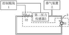
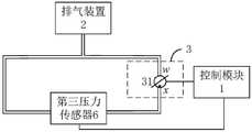
其中,如图3B和图3C所示,管路排气系统还包括设置在调节阀32与排气装置2之间的、用于检测第二管路内的压力的第二压力传感器5;控制模块1与第二压力传感器5连接,用于从第二压力传感器5获取第二管路内的压力,并在调节阀32的开度调节为第二预设开度阈值后,实时判定该第二管路内的压力是否降到第三预设压力,其中,第三预设压力小于第一预设压力,例如,第三预设压力略大于第一预设压力的一半。Wherein, as shown in FIG. 3B and FIG. 3C , the pipeline exhaust system also includes a second pressure sensor 5 arranged between the regulating
在调节阀32的开度调节为第二预设开度阈值后,控制模块1判断是否满足上述第三预设条件。若满足第三预设条件,则需要判定排气是否完成,即执行以下步骤(9);若不满足第三预设条件,则继续监测是否满足第三预设条件。After the opening of the regulating
(9)控制模块1判断管路是否满足初始排气条件。(9) The
在本公开中,若管路满足初始排气条件,则表明管路排气系统排气未完成,控制模块1发送第一预设排气信号至调节阀32,返回上述步骤(2)继续进行排气,直到管路不满足初始排气条件时为止。若管路不满足初始排气条件,则表明管路排气系统已完成排气,此时,可以结束排气,恢复到正常循环状态,即执行以下步骤(10)和步骤(11)。In the present disclosure, if the pipeline meets the initial exhaust conditions, it indicates that the pipeline exhaust system exhaust is not completed, the
(10)发送第四排气信号至调节阀32。(10) Send the fourth exhaust signal to the regulating
(11)调节阀32接收第四排气信号,将开度调节为100%,即管路进入正常循环状态。(11) The regulating
在上述实施方式中,通过不断切换调节阀的开度即可实现自动排气,并且,调节阀成本低廉,降低了系统成本。另外,由于整个排气过程无需水泵提供过大压力,因此,可以降低对水泵的功率需求,这样,使用低功率水泵就可满足管路排气系统的需求,进一步降低了系统成本。In the above embodiments, the automatic exhaust can be realized by continuously switching the opening of the regulating valve, and the regulating valve has low cost, which reduces the system cost. In addition, since the entire exhaust process does not require the water pump to provide excessive pressure, the power demand for the water pump can be reduced. In this way, the use of a low-power water pump can meet the needs of the pipeline exhaust system, further reducing the system cost.
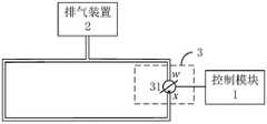
在另一种实施方式中,如图4所示,上述压力调节装置3包括水泵31,其中,水泵31的出水口通过第三管路与排气装置2连接,水泵31的进水口通过第四管路与排气装置2连接,水泵31为压力可调节水泵,并与控制模块31连接。如图4中所示,第三管路为水泵31的出水口至排气装置2之间的管路,第四管路为排气装置2值水泵31之间的管路。In another embodiment, as shown in FIG. 4, the above-mentioned
此时,第一预设状态为水泵31的压力为第四预设压力;第二预设状态为水泵31的压力为第五预设压力;第三预设状态为水泵31的压力为第六预设压力,其中,第五预设压力、第六预设压力、第四预设压力依次增大;初始状态为水泵31的压力为初始预设压力,其中,初始预设压力在第六预设压力和第四预设压力之间。即管路排气系统通过以下步骤[1]~步骤[11]来实现排气:At this time, the first preset state is that the pressure of the
[1]控制模块1检测管路是否满足初始排气条件。[1] The
控制模块1在检测到管路满足初始排气条件时,执行以下步骤[2];若检测到管路不满足初始排气条件,则继续检测是否满足初始排气条件,即返回步骤[1]。When the
[2]控制模块1发送第一预设排气信号至水泵31。[2] The
[3]水泵31接收第一预设排气信号,并基于第一预设排气信号将压力调节为第四预设压力。[3] The
在本公开中,管路处于正常循环状态时,水泵31的压力设置为初始预设压力,其中,初始预设压力小于第四预设压力。在管路满足初始排气条件时,水泵31的压力调节为第四预设压力,使得管路中循环液的流速增大,高流速的循环液将管路(尤其是管路拐角点和弯曲管道顶部位置处的气泡)中的气泡带走至排气装置2。示例地,第四预设压力为管路所能承受的最大压力值。In the present disclosure, when the pipeline is in a normal circulation state, the pressure of the
[4]控制模块1检测管路是否满足第一预设条件,并在检测到管路满足第一预设条件时,发送第二预设排气信号至水泵31。[4] The
在本公开实施例中,第一预设条件包括以下g、h中的任一者:In an embodiment of the present disclosure, the first preset condition includes any of the following g and h:
g、水泵的压力处于第四预设压力的持续时长达到第四预设时长。g. The duration of the pressure of the water pump being at the fourth preset pressure reaches the fourth preset duration.
其中,第四预设时长可以根据管路布置情况和水泵的能力确定,使得水泵的压力调节为第四预设压力期间,管路内的压力始终小于管路所能承受的最大压力值。Wherein, the fourth preset duration can be determined according to the layout of the pipeline and the capacity of the water pump, so that during the period when the pressure of the water pump is adjusted to the fourth preset pressure, the pressure in the pipeline is always lower than the maximum pressure value that the pipeline can withstand.
h、第三管路内的压力增到第七预设压力。h. The pressure in the third pipeline increases to the seventh preset pressure.
示例地,如图5A和图5C中所示,管路排气系统还包括设置在水泵31的出水口与排气装置2之间的、用于检测第三管路内的压力的第三压力传感器6;控制模块1与第三压力传感器6连接,用于从第三压力传感器6获取第三管路内的压力,并在水泵31的压力调节为第四预设压力后,实时判定该第三管路内的压力是否增到第七预设压力。Exemplarily, as shown in FIG. 5A and FIG. 5C , the pipeline exhaust system further includes a third pressure sensor provided between the water outlet of the
在水泵31的压力调节为第四预设压力后,控制模块1判断是否满足上述第四预设条件;若满足第四预设条件,则发送第二预设排气信号至水泵31;若不满足第四预设条件,则继续监测是否满足第四预设条件。After the pressure of the
[5]水泵31接收第二预设排气信号,并基于第二排气信号使将压力调节为第五预设压力。[5] The
在本公开中,在水泵31的压力调节为第四预设压力后,利用高流速循环液将气泡排出到排气装置2,之后,在满足第四预设条件时,水泵32的压力调节为第五预设压力,以使得管路压力不断变换,导致循环液流速变化,以使得管路系统中的气泡尽可能多的排出到排气装置2。示例地,第五预设压力为零。In the present disclosure, after the pressure of the
[6]控制模块1检测管路是否满足第二预设条件,并在检测到管路满足第二预设条件时,发送第三排气信号至水泵31。[6] The
在本公开实施例中,第二预设条件包括以下i、j中的任一者:In the embodiment of the present disclosure, the second preset condition includes any one of the following i and j:
i、水泵的压力处于第五预设压力的持续时长达到第五预设时长。i. The duration of the pressure of the water pump at the fifth preset pressure reaches the fifth preset duration.
其中,第五预设时长可以根据管路布置情况和水泵的能力确定。Wherein, the fifth preset duration can be determined according to the pipeline arrangement and the capacity of the water pump.
j、第三管路内的压力降到第八预设压力。j. The pressure in the third pipeline drops to the eighth preset pressure.
在本公开中,在水泵的压力调节为第五预设压力后,管路压力降低。在水泵的压力调节为第五预设压力后,可以实时判定第三管路内的压力是否降到第八预设压力,其中,第八预设压力小于第七预设压力,例如,第八预设压力为0.3MPa。In the present disclosure, after the pressure of the water pump is adjusted to the fifth preset pressure, the pipeline pressure decreases. After the pressure of the water pump is adjusted to the fifth preset pressure, it can be determined in real time whether the pressure in the third pipeline drops to the eighth preset pressure, wherein the eighth preset pressure is less than the seventh preset pressure, for example, the eighth preset pressure The preset pressure is 0.3MPa.
在水泵31的压力调节为第五预设压力后,控制模块1判断是否满足上述第二预设条件。若满足第二预设条件,则发送第三排气信号至水泵31;若不满足第二预设条件,则继续监测是否满足第二预设条件。After the pressure of the
[7]水泵31接收第三排气信号,并基于第三排气信号将压力调节为第六预设压力。[7] The
其中,第六预设压力小于初始预设压力、且大于第五预设压力。Wherein, the sixth preset pressure is less than the initial preset pressure and greater than the fifth preset pressure.
为了将排气装置2中的气泡能顺利排出,在满足第二预设条件时,将压力调节为第六预设压力。在使得循环液低速循环,这样,循环液经过水箱时,由于流速慢,循环液中的气泡容易浮出液面,从而通过排气装置2排出(例如,通过排气装置2上的排气口排出),实现了管路排气系统自动排气。In order to smoothly discharge the air bubbles in the
[8]控制模块1检测管路是否满足第三预设条件。[8] The
在本公开实施例中,第三预设条件包括以下k、q中的任一者:In the embodiment of the present disclosure, the third preset condition includes any one of the following k and q:
k、水泵的压力处于第六预设压力的持续时长达到第六预设时长。k. The duration for which the pressure of the water pump is at the sixth preset pressure reaches the sixth preset duration.
其中,第六预设时长可以根据管路布置情况和水泵的能力确定。Wherein, the sixth preset duration can be determined according to the pipeline arrangement and the capacity of the water pump.
q、第四管路内的压力降到第九预设压力。q. The pressure in the fourth pipeline drops to the ninth preset pressure.
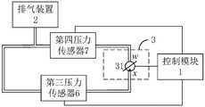
在本公开中,如图5B和图5C所示,管路排气系统还包括设置在排气装置2与水泵31进水口之间的、用于检测第四管路内的压力的第四压力传感器7;控制模块1与第四压力传感器7连接,用于从第四压力传感器7获取第四管路内的压力,并在水泵31的压力调节为第六预设压力后,实时判定该第四管路内的压力是否降到第九预设压力,其中,第九预设压力大于第八预设压力、且小于第七预设压力,例如,第九预设压力为1.5MPa。其中,水泵31的压力从第五预设压力调节为第六预设压力时,第四管路中的压力会减小。In the present disclosure, as shown in FIG. 5B and FIG. 5C , the pipeline exhaust system further includes a fourth pressure sensor set between the
在水泵31的压力调节为第六预设压力后,判断是否满足上述第三预设条件。若满足第三预设条件,则需要判定排气是否完成,即执行以下步骤[9];若不满足第三预设条件,则继续监测是否满足第三预设条件。After the pressure of the
[9]控制模块1判断管路是否满足初始排气条件。[9] The
在本公开中,若管路满足初始排气条件,则表明管路排气系统排气未完成,控制模块1发送第一预设排气信号至水泵31,返回上述步骤[2]继续进行排气,直到管路不满足初始排气条件时为止。若管路不满足初始排气条件,则表明管路排气系统已完成排气,此时,可以结束排气,恢复到正常循环状态,即执行以下步骤[10]和步骤[11]。In the present disclosure, if the pipeline satisfies the initial exhaust condition, it indicates that the exhaust of the pipeline exhaust system is not completed, the
[10]发送第四排气信号至水泵31。[10] Send the fourth exhaust signal to the
[11]水泵31接收第四排气信号,将压力调节为初始预设压力,即管路进入正常循环状态。[11] The
在上述实施方式中,通过不断调整压力可调节水泵的压力即可实现自动排气,而无需设置调节阀,从而避免了因布置空间有限等原因导致的无法设置调节阀的问题。另外,压力可调节水泵的成本相对于真空加注机、外接排气装置的成本低,可以在实现管路排气系统自动排气的同时,控制系统成本。In the above embodiments, the pressure of the adjustable water pump can be adjusted continuously to realize automatic exhaust without setting a regulating valve, thereby avoiding the problem that the regulating valve cannot be installed due to limited layout space and the like. In addition, the cost of the pressure-adjustable water pump is lower than that of the vacuum filling machine and the external exhaust device, which can control the system cost while realizing the automatic exhaust of the pipeline exhaust system.
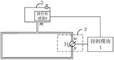
下面针对上述控制模块1判断管路是否满足初始排气条件的具体实施方式进行详细说明。具体来说,如图6A、图6B所示,排气装置2为水箱,水箱包括进气口m和排气口n,进气口m与管路连通,排气口n连通外部环境,上述管路排气系统还包括液位传感器8,设置在水箱内,用于实时检测水箱的液位。The following describes in detail the specific implementation of the
控制模块1,与液位传感器8连接,还用于通过液位传感器8实时获取水箱的液位;控制模块1用于在水箱的液位在第七预设时长内的变化量大于预设液位阈值时,确定管路满足初始排气条件。The
在本公开中,当管路中有大量气体时,水泵31处于工作状态会增大管路压力,导致管路中的气体压缩,造成水箱给管路补充循环液,从而出现水箱液位变化。因此,通过监测水箱液位变化情况,来确定管路是否存在大量气体,并在确定存在大量气体时,确定管路满足初始排气条件。具体来说,控制模块1可以通过判断水箱的液位在第七预设时长(例如,0.5s)内的变化量是否大于预设液位阈值的方式来确定管路是否满足初始排气条件。其中,若水箱的液位在第七预设时长内的变化量大于预设液位阈值,则确定管路满足初始排气条件;若水箱的液位在第七预设时长内的变化量小于或等于预设液位阈值,则确定管路排气系统不满足初始排气条件In the present disclosure, when there is a large amount of gas in the pipeline, the
此外,为了避免水泵31空转或者堵转(即水泵通电、但不运转)导致管路排气系统损坏,在管路处于正常循环状态和排气过程中时,实时监测水泵是否异常,并在水泵异常时,控制水泵停止工作和/或发出异常告警。In addition, in order to avoid damage to the pipeline exhaust system caused by the
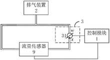
具体来说,如图7A、7B中所示,上述管路排气系统还包括流量传感器9,用于实时检测管路的流量;控制模块1还用于通过流量传感器9获取管路的流量,并判断流量是否超出预设流量范围,并在流量超出预设流量范围时,发送异常信号至压力调节装置3;压力调节装置3还用于接收异常信号,并停止工作和/或发出异常告警。Specifically, as shown in Figures 7A and 7B, the pipeline exhaust system also includes a
在本公开中,若管路的流量超出预设流量范围,则表明水泵出现空转、堵转等异常,此时,为了避免管路排气系统损坏,压力调节装置3停止工作和/或发出异常告警;若管路的流量位于预设流量范围内,则表明水泵无异常,此时,可以继续监测水泵是否异常。In the present disclosure, if the flow rate of the pipeline exceeds the preset flow range, it indicates that the water pump has abnormalities such as idling and stalling. Alarm; if the flow of the pipeline is within the preset flow range, it means that the water pump is normal. At this time, you can continue to monitor whether the water pump is abnormal.
本公开还提供一种热管理系统,包括:如前述的管路排气系统、冷却装置、加热装置以及冷却负载。The present disclosure also provides a thermal management system, including: the aforementioned pipeline exhaust system, a cooling device, a heating device, and a cooling load.
在本公开中,冷却装置可以例如是散热片、风扇等;加热装置可以例如是PTC加热器;以上述管路排气系统可以为车辆的热管理系统为例,冷却负载可以包括动力电池、驱动电机和其他需要冷却的设备。In the present disclosure, the cooling device may be, for example, a heat sink, a fan, etc.; the heating device may be, for example, a PTC heater; taking the above-mentioned pipeline exhaust system as an example of a vehicle thermal management system, the cooling load may include a power battery, a drive Motors and other equipment requiring cooling.
本公开还提供一种车辆,包括上述热管理系统。The present disclosure also provides a vehicle, including the above thermal management system.
以上结合附图详细描述了本公开的优选实施方式,但是,本公开并不限于上述实施方式中的具体细节,在本公开的技术构思范围内,可以对本公开的技术方案进行多种简单变型,这些简单变型均属于本公开的保护范围。The preferred embodiments of the present disclosure have been described in detail above in conjunction with the accompanying drawings. However, the present disclosure is not limited to the specific details of the above embodiments. Within the scope of the technical concept of the present disclosure, various simple modifications can be made to the technical solutions of the present disclosure. These simple modifications all belong to the protection scope of the present disclosure.
另外需要说明的是,在上述具体实施方式中所描述的各个具体技术特征,在不矛盾的情况下,可以通过任何合适的方式进行组合。为了避免不必要的重复,本公开对各种可能的组合方式不再另行说明。In addition, it should be noted that the various specific technical features described in the above specific implementation manners may be combined in any suitable manner if there is no contradiction. In order to avoid unnecessary repetition, various possible combinations are not further described in this disclosure.
此外,本公开的各种不同的实施方式之间也可以进行任意组合,只要其不违背本公开的思想,其同样应当视为本公开所公开的内容。In addition, various implementations of the present disclosure can be combined arbitrarily, as long as they do not violate the idea of the present disclosure, they should also be regarded as the content disclosed in the present disclosure.
Claims (10)
Translated fromChinesePriority Applications (1)
| Application Number | Priority Date | Filing Date | Title |
|---|---|---|---|
| CN202110735689.2ACN115539193B (en) | 2021-06-30 | 2021-06-30 | Pipeline exhaust system, thermal management system and vehicle |
Applications Claiming Priority (1)
| Application Number | Priority Date | Filing Date | Title |
|---|---|---|---|
| CN202110735689.2ACN115539193B (en) | 2021-06-30 | 2021-06-30 | Pipeline exhaust system, thermal management system and vehicle |
Publications (2)
| Publication Number | Publication Date |
|---|---|
| CN115539193Atrue CN115539193A (en) | 2022-12-30 |
| CN115539193B CN115539193B (en) | 2025-08-05 |
Family
ID=84717096
Family Applications (1)
| Application Number | Title | Priority Date | Filing Date |
|---|---|---|---|
| CN202110735689.2AActiveCN115539193B (en) | 2021-06-30 | 2021-06-30 | Pipeline exhaust system, thermal management system and vehicle |
Country Status (1)
| Country | Link |
|---|---|
| CN (1) | CN115539193B (en) |
Citations (2)
| Publication number | Priority date | Publication date | Assignee | Title |
|---|---|---|---|---|
| US5241926A (en)* | 1991-08-09 | 1993-09-07 | Mazda Motor Corporation | Engine cooling apparatus |
| CN112665098A (en)* | 2020-12-09 | 2021-04-16 | 珠海格力电器股份有限公司 | Air conditioner pipeline pressure control method, controller and air conditioner |
- 2021
- 2021-06-30CNCN202110735689.2Apatent/CN115539193B/enactiveActive
Patent Citations (2)
| Publication number | Priority date | Publication date | Assignee | Title |
|---|---|---|---|---|
| US5241926A (en)* | 1991-08-09 | 1993-09-07 | Mazda Motor Corporation | Engine cooling apparatus |
| CN112665098A (en)* | 2020-12-09 | 2021-04-16 | 珠海格力电器股份有限公司 | Air conditioner pipeline pressure control method, controller and air conditioner |
Also Published As
| Publication number | Publication date |
|---|---|
| CN115539193B (en) | 2025-08-05 |
Similar Documents
| Publication | Publication Date | Title |
|---|---|---|
| CN110274361B (en) | Water multi-connected air conditioning system and control method of variable-frequency water pump thereof | |
| CA2955780C (en) | Intelligent sea water cooling system | |
| CN102562248A (en) | Cooling system and cooling method for hydraulic traveling machine, and hydraulic excavator | |
| WO2005026509A1 (en) | Fan rpm control method | |
| CN113871651A (en) | Double-water-pump heat dissipation system of fuel cell and control method | |
| CN103883384A (en) | Hydraulic radiating system, construction crane and hydraulic radiating capability adjusting method | |
| KR101602475B1 (en) | The optimal control method of inverter booster pump | |
| CN113581016B (en) | Idle speed control method of fuel cell system and related equipment | |
| CN107763199B (en) | A kind of hydraulic power unit and its control method | |
| CN114801809A (en) | Storage and charging integrated equipment thermal management system and control method thereof | |
| CN110858745A (en) | Cooling device and method for submarine motor | |
| CN120194557A (en) | A method and system for balancing water supply flow in an open cooling tower | |
| CN115539193A (en) | Pipeline exhaust system, thermal management system and vehicle | |
| CN114876851A (en) | Air suspension fan control system | |
| KR101369780B1 (en) | Sensorless variable flow rate control apparatus of pump using context aware algorithm and cotrol method thereof | |
| CN111255757A (en) | Efficient and energy-saving load-sensitive hydraulic system realized through variable displacement motor | |
| JP4926347B2 (en) | Compressed air supply equipment | |
| CN108678936B (en) | Pump operation control method | |
| CN107420182A (en) | The engine thermal management system and method for a kind of distributed AC servo system | |
| US20160252086A1 (en) | Method for operating a pump unit, pump unit and use thereof | |
| CN107787162B (en) | Circulation cooling device adopting pure water medium and application method thereof | |
| CN114865019A (en) | Fuel cell thermal management system and pressure regulating method thereof | |
| CN107765733A (en) | Emitter high-power electronic device circulating cooling control device | |
| CN110057137A (en) | Multi-machine parallel heat pump system | |
| CN218941626U (en) | Air-cooled heat exchange system |
Legal Events
| Date | Code | Title | Description |
|---|---|---|---|
| PB01 | Publication | ||
| PB01 | Publication | ||
| SE01 | Entry into force of request for substantive examination | ||
| SE01 | Entry into force of request for substantive examination | ||
| GR01 | Patent grant | ||
| GR01 | Patent grant |