CN115530889A - A tumor sampling device for convenient isolation of tumors - Google Patents
A tumor sampling device for convenient isolation of tumorsDownload PDFInfo
- Publication number
- CN115530889A CN115530889ACN202211393828.9ACN202211393828ACN115530889ACN 115530889 ACN115530889 ACN 115530889ACN 202211393828 ACN202211393828 ACN 202211393828ACN 115530889 ACN115530889 ACN 115530889A
- Authority
- CN
- China
- Prior art keywords
- needle
- sampling
- puncture
- assembly
- transmission
- Prior art date
- Legal status (The legal status is an assumption and is not a legal conclusion. Google has not performed a legal analysis and makes no representation as to the accuracy of the status listed.)
- Granted
Links
Images


Classifications
- A—HUMAN NECESSITIES
- A61—MEDICAL OR VETERINARY SCIENCE; HYGIENE
- A61B—DIAGNOSIS; SURGERY; IDENTIFICATION
- A61B10/00—Instruments for taking body samples for diagnostic purposes; Other methods or instruments for diagnosis, e.g. for vaccination diagnosis, sex determination or ovulation-period determination; Throat striking implements
- A61B10/02—Instruments for taking cell samples or for biopsy
- A61B10/0233—Pointed or sharp biopsy instruments
- A61B10/0266—Pointed or sharp biopsy instruments means for severing sample
- A61B10/0275—Pointed or sharp biopsy instruments means for severing sample with sample notch, e.g. on the side of inner stylet
- A—HUMAN NECESSITIES
- A61—MEDICAL OR VETERINARY SCIENCE; HYGIENE
- A61B—DIAGNOSIS; SURGERY; IDENTIFICATION
- A61B90/00—Instruments, implements or accessories specially adapted for surgery or diagnosis and not covered by any of the groups A61B1/00 - A61B50/00, e.g. for luxation treatment or for protecting wound edges
- A61B90/10—Instruments, implements or accessories specially adapted for surgery or diagnosis and not covered by any of the groups A61B1/00 - A61B50/00, e.g. for luxation treatment or for protecting wound edges for stereotaxic surgery, e.g. frame-based stereotaxis
- A61B90/11—Instruments, implements or accessories specially adapted for surgery or diagnosis and not covered by any of the groups A61B1/00 - A61B50/00, e.g. for luxation treatment or for protecting wound edges for stereotaxic surgery, e.g. frame-based stereotaxis with guides for needles or instruments, e.g. arcuate slides or ball joints
Landscapes
- Health & Medical Sciences (AREA)
- Life Sciences & Earth Sciences (AREA)
- Surgery (AREA)
- Biomedical Technology (AREA)
- Engineering & Computer Science (AREA)
- Heart & Thoracic Surgery (AREA)
- Medical Informatics (AREA)
- Molecular Biology (AREA)
- Pathology (AREA)
- Animal Behavior & Ethology (AREA)
- General Health & Medical Sciences (AREA)
- Public Health (AREA)
- Veterinary Medicine (AREA)
- Nuclear Medicine, Radiotherapy & Molecular Imaging (AREA)
- Oral & Maxillofacial Surgery (AREA)
- Measurement Of The Respiration, Hearing Ability, Form, And Blood Characteristics Of Living Organisms (AREA)
Abstract
Description
Translated fromChinese技术领域technical field
本发明属于医疗取样设备技术领域,尤其涉及一种方便分离肿瘤的肿瘤取样设备。The invention belongs to the technical field of medical sampling equipment, in particular to a tumor sampling equipment for conveniently separating tumors.
背景技术Background technique
肿瘤是指机体在各种致瘤因子作用下,局部组织细胞增生所形成的新生物,因为这种新生物多呈占位性块状突起,也称赘生物,在判断肿瘤是良性还是恶性时需要医生利用取样装置对肿瘤采样进行化验检测。但是现有的取样设备通过负压吸取肿瘤组织,这样的方法创口小,而且减轻了患者的痛苦,而传统的针管取样,单靠负压取样不容易一次成功,吸附过程不够精准,穿刺过程不够稳定,截取的样品不易脱离,还需要手动脱离,整体取样过程繁琐;因此,亟需一种自动截取肿瘤样品、释放肿瘤样品,还可以准确把握穿刺深度,使整个取样过程更加顺利与稳定的方便分离肿瘤的肿瘤取样设备。Tumor refers to the new organism formed by the proliferation of local tissue cells under the action of various tumorigenic factors, because this new organism is mostly a space-occupying blocky protrusion, also known as a neoplasm, when judging whether a tumor is benign or malignant It is necessary for a doctor to use a sampling device to perform laboratory tests on tumor samples. However, the existing sampling equipment absorbs tumor tissue through negative pressure. This method has a small wound and reduces the pain of the patient. However, the traditional needle sampling is not easy to succeed at one time only by negative pressure sampling. The adsorption process is not accurate enough, and the puncture process is not enough. Stable, the intercepted sample is not easy to detach, and it needs to be detached manually, and the overall sampling process is cumbersome; therefore, there is an urgent need for a convenient method that can automatically intercept and release tumor samples, and can accurately grasp the puncture depth to make the entire sampling process smoother and more stable. Tumor sampling device for isolating tumors.
发明内容Contents of the invention
本发明的目的是提供一种方便分离肿瘤的肿瘤取样设备,以解决上述问题,达到有效提高取样稳定和精确的目的。The object of the present invention is to provide a tumor sampling device for conveniently separating tumors, so as to solve the above problems and achieve the purpose of effectively improving the stability and accuracy of sampling.
为实现上述目的,本发明提供了如下方案:一种方便分离肿瘤的肿瘤取样设备,包括固定壳体,所述固定壳体的侧壁上固定连接有穿刺手柄,所述固定壳体靠近所述穿刺手柄的一端连接有穿刺深度检测单元,所述固定壳体远离所述穿刺深度检测单元的一端设置为取样端,所述取样端连接有穿刺针总成,所述穿刺针总成远离所述取样端的一端设置为穿刺端,所述穿刺针总成远离所述穿刺端的一端穿过所述取样端且位于所述固定壳体内,所述固定壳体内开设有第一空腔,所述第一空腔内设置有驱动单元,所述穿刺针总成通过所述驱动单元驱动取样,所述穿刺针总成内连通有辅助取样单元,所述辅助取样单元用于辅助所述驱动单元取样且还便于释放样品。In order to achieve the above object, the present invention provides the following solution: a tumor sampling device for conveniently separating tumors, including a fixed housing, a puncture handle is fixedly connected to the side wall of the fixed housing, and the fixed housing is close to the One end of the puncture handle is connected with a puncture depth detection unit, and the end of the fixed housing away from the puncture depth detection unit is set as a sampling end, and the sampling end is connected with a puncture needle assembly, and the puncture needle assembly is far away from the One end of the sampling end is set as a puncture end, and the end of the puncture needle assembly away from the puncture end passes through the sampling end and is located in the fixed housing. A first cavity is opened in the fixed housing, and the first A drive unit is arranged in the cavity, and the puncture needle assembly drives sampling through the drive unit, and an auxiliary sampling unit communicates with the puncture needle assembly, and the auxiliary sampling unit is used to assist the drive unit in sampling and also Easy to release samples.
优选的,所述穿刺针总成包括外针组件与内针组件,所述外针组件套设在所述内针组件的外侧,所述外针组件远离所述穿刺端的一端可拆卸连接在所述取样端上,所述内针组件穿过所述取样端且位于所述固定壳体内的一端与所述驱动单元的输出端传动连接,所述辅助取样单元穿过所述外针组件与所述内针组件内连通。Preferably, the puncture needle assembly includes an outer needle assembly and an inner needle assembly, the outer needle assembly is sleeved on the outside of the inner needle assembly, and the end of the outer needle assembly away from the puncture end is detachably connected to the On the sampling end, one end of the inner needle assembly that passes through the sampling end and is located in the fixed housing is in transmission connection with the output end of the drive unit, and the auxiliary sampling unit passes through the outer needle assembly and is connected to the The above-mentioned inner needle assembly is internally connected.
优选的,所述内针组件包括依次固定连接的滑杆总成、传动针芯与内取样针头,所述滑杆总成与所述驱动单元的输出端传动连接,所述滑杆总成转动的同时沿取样方向移动,所述传动针芯贯穿所述取样端的一端位于所述外针组件内,所述内取样针头靠近所述穿刺端设置,所述辅助取样单元与所述传动针芯、内取样针头内侧连通。Preferably, the inner needle assembly includes a sliding rod assembly, a driving needle core and an inner sampling needle fixedly connected in sequence, the sliding rod assembly is in transmission connection with the output end of the drive unit, and the sliding rod assembly rotates While moving along the sampling direction, one end of the transmission needle core passing through the sampling end is located in the outer needle assembly, the inner sampling needle is arranged close to the puncture end, the auxiliary sampling unit is connected to the transmission needle core, The inside of the inner sampling needle is connected.
优选的,所述内取样针头包括切削针芯与薄壁内针,所述薄壁内针套设在所述切削针芯的外侧,所述切削针芯的一端与所述传动针芯远离所述固定壳体的一端同轴心固定连接,所述切削针芯的另一端固定连接有切削刃,所述切削刃靠近所述穿刺端,所述切削针芯的侧壁上开设有螺纹槽,所述切削针芯通过所述螺纹槽形成空心薄片螺纹状结构,所述切削刃位于所述螺纹槽远离所述传动针芯的一端,所述薄壁内针远离所述切削刃的一端同轴心固定连接在所述切削针芯上,所述薄壁内针壁厚小于所述传动针芯的壁厚。Preferably, the inner sampling needle includes a cutting needle core and a thin-walled inner needle, the thin-walled inner needle is sleeved on the outside of the cutting needle core, and one end of the cutting needle core is away from the transmission needle core. One end of the fixed housing is fixedly connected with the axis, the other end of the cutting needle core is fixedly connected with a cutting edge, the cutting edge is close to the puncture end, and a thread groove is opened on the side wall of the cutting needle core, The cutting needle core forms a hollow sheet thread-like structure through the thread groove, the cutting edge is located at the end of the thread groove away from the transmission needle core, and the end of the thin-walled inner needle away from the cutting edge is coaxial The core is fixedly connected to the cutting needle core, and the wall thickness of the thin-walled inner needle is smaller than the wall thickness of the transmission needle core.
优选的,所述外针组件包括依次同轴心固定连接的螺纹端头、第一外针、第二外针与第三外针,所述螺纹端头靠近所述取样端的一端与所述固定壳体螺纹连接,所述第三外针套设在所述切削针芯的外侧,所述第三外针的壁厚小于所述第二外针的壁厚,所述辅助取样单元通过所述第一外针与所述第二外针内侧连通。Preferably, the outer needle assembly includes a threaded end, a first outer needle, a second outer needle, and a third outer needle that are fixedly connected with the axis in sequence, and the end of the threaded end that is close to the sampling end is connected to the fixed The casing is threadedly connected, the third outer needle is sleeved on the outside of the cutting needle core, the wall thickness of the third outer needle is smaller than the wall thickness of the second outer needle, and the auxiliary sampling unit passes through the The first outer needle communicates with the inside of the second outer needle.
优选的,所述驱动单元包括固定连接在所述第一空腔内的电机,所述电机的旋转轴同轴心固定连接有螺纹杆,所述螺纹杆的外侧螺纹套设有传动支架总成,所述传动支架总成沿取样方向滑动连接在所述第一空腔内,所述传动支架总成远离所述电机的一端与所述螺纹杆的一端之间设置有间隙,所述滑杆总成远离所述传动针芯的一端穿过所述传动支架总成且还伸入所述螺纹杆内,所述传动支架总成与所述滑杆总成、传动针芯传动连接,所述螺纹杆与所述传动支架总成通过所述滑杆总成驱动传动针芯伸缩取样。Preferably, the drive unit includes a motor fixedly connected in the first cavity, the rotating shaft of the motor is fixedly connected with the coaxial center with a threaded rod, and the outer threaded sleeve of the threaded rod is provided with a transmission bracket assembly , the transmission bracket assembly is slidably connected in the first cavity along the sampling direction, a gap is provided between the end of the transmission bracket assembly away from the motor and the end of the threaded rod, and the sliding rod The end of the assembly away from the transmission needle core passes through the transmission bracket assembly and also extends into the threaded rod. The transmission bracket assembly is connected with the sliding rod assembly and the transmission needle core in transmission. The threaded rod and the transmission bracket assembly drive the transmission needle core for telescopic sampling through the slide rod assembly.
优选的,所述滑杆总成包括与所述传动针芯同轴心固定连接的轴芯,所述螺纹杆远离所述电机的一端套设在所述轴芯穿过所述传动支架总成的一端外侧,所述螺纹杆内对称开设有第二滑槽,所述第二滑槽沿取样方向设置,所述轴芯的外侧对称固定连接有耳板,两组所述耳板分别对应滑动连接在两组所述第二滑槽内,所述传动针芯靠近所述轴芯的一端转动连接在所述传动支架总成上,所述传动支架总成远离所述电机的一端与所述固定壳体内靠近所述取样端的一端之间抵接有弹簧,所述弹簧套设在所述传动针芯的外侧。Preferably, the slide bar assembly includes a shaft core fixedly connected with the transmission needle core coaxially, and the end of the threaded rod away from the motor is sheathed on the shaft core and passes through the transmission bracket assembly On the outer side of one end of the threaded rod, a second chute is symmetrically provided in the threaded rod, and the second chute is arranged along the sampling direction. The outer side of the shaft core is symmetrically fixedly connected with ear plates, and the two sets of ear plates slide correspondingly. Connected in two groups of the second chute, the end of the transmission needle core close to the shaft core is rotatably connected to the transmission bracket assembly, and the end of the transmission bracket assembly away from the motor is connected to the A spring abuts against one end of the fixed housing close to the sampling end, and the spring is sheathed on the outside of the driving needle core.
优选的,所述传动支架总成包括螺纹套设在所述螺纹杆外侧的螺纹套筒,所述螺纹套筒的边部对称固定连接有固定连杆,两组所述固定连杆远离所述电机的同一端固定连接且还与所述螺纹杆之间设置有所述间隙,所述传动针芯靠近所述轴芯的一端外侧固定套设有固定圆环,两组所述固定连杆靠近所述传动针芯的同一端外侧螺纹套设有螺纹端盖,所述传动针芯穿过所述螺纹端盖中心,所述固定圆环位于所述螺纹端盖内侧与两组所述固定连杆之间,所述固定圆环与所述螺纹端盖内侧底壁之间、所述固定圆环与两组所述固定连杆之间分别滚动配合有若干滚珠,所述弹簧抵接在所述螺纹端盖与所述固定壳体内靠近所述取样端的一端之间。Preferably, the transmission bracket assembly includes a threaded sleeve threaded on the outside of the threaded rod, the side of the threaded sleeve is symmetrically fixedly connected to the fixed connecting rod, and the two sets of fixed connecting rods are far away from the The same end of the motor is fixedly connected with the threaded rod, and the gap is provided. The outer fixed sleeve of the transmission needle core close to the shaft core is provided with a fixed ring, and the two sets of fixed connecting rods are close to each other. The same end of the transmission needle core is provided with a threaded end cap on the outer threaded sleeve, the transmission needle core passes through the center of the threaded end cap, and the fixed ring is located inside the threaded end cap and two sets of the fixed connection Between the rods, between the fixed ring and the inner bottom wall of the threaded end cap, and between the fixed ring and the two sets of fixed connecting rods, there are a number of rolling balls respectively, and the spring abuts against the Between the threaded end cap and the end of the fixed housing close to the sampling end.
优选的,两组所述固定连杆的背离侧分别竖向固定连接有上滑块与下滑块,所述上滑块靠近所述电机设置,所述第一空腔内对称固定连接有固定板,两组所述固定板的相对侧分别开设有第一滑槽,所有的所述上滑块与所述下滑块沿取样方向滑动连接在两组所述第一滑槽内。Preferably, upper sliders and lower sliders are vertically and fixedly connected to the away sides of the two sets of fixed connecting rods respectively, the upper sliders are arranged close to the motor, and the first cavity is symmetrically and fixedly connected with fixed sliders. The opposite sides of the two groups of fixed plates are provided with first chute respectively, and all the upper sliders and the lower sliders are slidably connected in the two groups of first chute along the sampling direction.
优选的,所述穿刺深度检测单元包括显示屏与距离传感器,所述显示屏固定连接在所述固定壳体远离所述取样端的一端外侧,所述距离传感器固定连接在所述第一空腔内,所述距离传感器的检测端与一组所述上滑块对应设置。Preferably, the puncture depth detection unit includes a display screen and a distance sensor, the display screen is fixedly connected to the outside of the end of the fixed housing away from the sampling end, and the distance sensor is fixedly connected to the first cavity , the detection end of the distance sensor is set corresponding to a group of the upper sliders.
本发明具有如下技术效果:在CT的引导下,通过手持穿刺手柄将穿刺针总成穿过皮肤并伸入肿瘤处;穿刺深度检测单元的主要作用是通过穿刺针总成的位移来判断穿刺深度数据,并与CT有效结合,达到精确穿刺的目的;驱动单元的主要作用是驱动穿刺针总成刺入肿瘤,截取部分肿瘤样品后脱离肿瘤;辅助取样单元的主要作用是辅助驱动单元,使取样过程更加顺利、稳定,同时还可以辅助驱动单元使样品脱离穿刺针总成;整体上,本申请可以自动截取肿瘤样品、释放肿瘤样品,还可以准确把握穿刺深度,使整个取样过程更加顺利与稳定。The present invention has the following technical effects: under the guidance of CT, the puncture needle assembly passes through the skin and extends into the tumor by holding the puncture handle; the main function of the puncture depth detection unit is to judge the puncture depth through the displacement of the puncture needle assembly The main function of the driving unit is to drive the puncture needle assembly to penetrate the tumor, and to intercept part of the tumor sample and then separate from the tumor; the main function of the auxiliary sampling unit is to assist the driving unit to make the sampling The process is smoother and more stable, and at the same time, it can assist the driving unit to separate the sample from the puncture needle assembly; on the whole, this application can automatically intercept and release tumor samples, and can also accurately grasp the puncture depth, making the whole sampling process smoother and more stable .
附图说明Description of drawings
为了更清楚地说明本发明实施例或现有技术中的技术方案,下面将对实施例中所需要使用的附图作简单地介绍,显而易见地,下面描述中的附图仅仅是本发明的一些实施例,对于本领域普通技术人员来讲,在不付出创造性劳动的前提下,还可以根据这些附图获得其他的附图。In order to more clearly illustrate the technical solutions in the embodiments of the present invention or the prior art, the following will briefly introduce the accompanying drawings required in the embodiments. Obviously, the accompanying drawings in the following description are only some of the present invention. Embodiments, for those of ordinary skill in the art, other drawings can also be obtained based on these drawings without any creative effort.
图1为本发明取样设备外观示意图;Fig. 1 is the appearance schematic diagram of sampling equipment of the present invention;
图2为本发明取样设备内部结构示意图;Fig. 2 is a schematic diagram of the internal structure of the sampling device of the present invention;
图3为图2中的A局部放大示意图;Fig. 3 is a partially enlarged schematic diagram of A in Fig. 2;
图4为图2中的B局部放大示意图;Fig. 4 is the partially enlarged schematic view of B in Fig. 2;
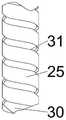
图5为本发明切削针芯结构示意图;Fig. 5 is a schematic diagram of the structure of the cutting needle core of the present invention;
图6为本发明螺纹杆断面示意图;Fig. 6 is a cross-sectional schematic diagram of a threaded rod of the present invention;
其中,1、穿刺手柄;2、启动开关;3、固定壳体;4、显示屏;5、螺纹端头;6、负压管;7、第一外针;8、第二外针;9、第三外针;10、第一空腔;11、电机;12、距离传感器;13、固定圆盘;14、固定套;15、上滑块;16、螺纹套筒;17、下滑块;18、固定连杆;19、螺纹杆;20、轴芯;21、螺纹端盖;22、过孔;23、传动针芯;24、第一滑槽;25、切削针芯;26、耳板;27、滚珠;28、固定圆环;29、薄壁内针;30、切削刃;31、螺纹槽;32、第二滑槽;33、针口;34、固定板;35、第二空腔;36、注液管;37、三通接头;38、弹簧。Among them, 1. puncture handle; 2. Start switch; 3. Fixed shell; 4. Display screen; 5. Threaded end; 6. Negative pressure tube; 7. First outer needle; 8. Second outer needle; 9 , the third outer needle; 10, the first cavity; 11, the motor; 12, the distance sensor; 13, the fixed disc; 14, the fixed sleeve; 15, the upper slider; 16, the threaded sleeve; 17, the lower slider ; 18, fixed connecting rod; 19, threaded rod; 20, shaft core; 21, threaded end cap; 22, through hole; 23, transmission needle core; 24, first chute; 25, cutting needle core; 26, ear Plate; 27, ball; 28, fixed ring; 29, thin-walled inner needle; 30, cutting edge; 31, thread groove; 32, second chute; 33, pin mouth; 34, fixed plate; 35, second Cavity; 36, liquid injection pipe; 37, tee joint; 38, spring.
具体实施方式detailed description
下面将结合本发明实施例中的附图,对本发明实施例中的技术方案进行清楚、完整地描述,显然,所描述的实施例仅仅是本发明一部分实施例,而不是全部的实施例。基于本发明中的实施例,本领域普通技术人员在没有做出创造性劳动前提下所获得的所有其他实施例,都属于本发明保护的范围。The following will clearly and completely describe the technical solutions in the embodiments of the present invention with reference to the accompanying drawings in the embodiments of the present invention. Obviously, the described embodiments are only some, not all, embodiments of the present invention. Based on the embodiments of the present invention, all other embodiments obtained by persons of ordinary skill in the art without making creative efforts belong to the protection scope of the present invention.
为使本发明的上述目的、特征和优点能够更加明显易懂,下面结合附图和具体实施方式对本发明作进一步详细的说明。In order to make the above objects, features and advantages of the present invention more comprehensible, the present invention will be further described in detail below in conjunction with the accompanying drawings and specific embodiments.
参照图1-6所示,本发明提供了一种方便分离肿瘤的肿瘤取样设备,包括固定壳体3,固定壳体3的侧壁上固定连接有穿刺手柄1,固定壳体3靠近穿刺手柄1的一端连接有穿刺深度检测单元,固定壳体3远离穿刺深度检测单元的一端设置为取样端,取样端连接有穿刺针总成,穿刺针总成远离取样端的一端设置为穿刺端,穿刺针总成远离穿刺端的一端穿过取样端且位于固定壳体3内,固定壳体3内开设有第一空腔10,第一空腔10内设置有驱动单元,穿刺针总成通过驱动单元驱动取样,穿刺针总成内连通有辅助取样单元,辅助取样单元用于辅助驱动单元取样且还便于释放样品。Referring to Figures 1-6, the present invention provides a tumor sampling device for conveniently separating tumors, including a fixed housing 3, a puncture handle 1 is fixedly connected to the side wall of the fixed housing 3, and the fixed housing 3 is close to the puncture handle One end of 1 is connected with a puncture depth detection unit, and the end of the fixed housing 3 away from the puncture depth detection unit is set as a sampling end, the sampling end is connected with a puncture needle assembly, and the end of the puncture needle assembly away from the sampling end is set as a puncture end, the puncture needle The end of the assembly away from the puncture end passes through the sampling end and is located in the fixed housing 3. A
在CT的引导下,通过手持穿刺手柄1将穿刺针总成穿过皮肤并伸入肿瘤处;穿刺深度检测单元的主要作用是通过穿刺针总成的位移来判断穿刺深度数据,并与CT有效结合,达到精确穿刺的目的;驱动单元的主要作用是驱动穿刺针总成刺入肿瘤,截取部分肿瘤样品后脱离肿瘤;辅助取样单元的主要作用是辅助驱动单元,使取样过程更加顺利、稳定,同时还可以辅助驱动单元使样品脱离穿刺针总成;整体上,本申请可以自动截取肿瘤样品、释放肿瘤样品,还可以准确把握穿刺深度,使整个取样过程更加顺利与稳定。Under the guidance of CT, the puncture needle assembly passes through the skin and extends into the tumor by holding the puncture handle 1; the main function of the puncture depth detection unit is to judge the puncture depth data through the displacement of the puncture needle assembly, and it is effective with CT combined to achieve the purpose of precise puncture; the main function of the driving unit is to drive the puncture needle assembly to penetrate into the tumor, and to intercept part of the tumor sample and then separate from the tumor; the main function of the auxiliary sampling unit is to assist the driving unit to make the sampling process smoother and more stable. At the same time, it can also assist the driving unit to separate the sample from the puncture needle assembly; on the whole, the application can automatically intercept and release tumor samples, and can accurately grasp the puncture depth, making the whole sampling process smoother and more stable.
进一步优化方案,穿刺针总成包括外针组件与内针组件,外针组件套设在内针组件的外侧,外针组件远离穿刺端的一端可拆卸连接在取样端上,内针组件穿过取样端且位于固定壳体3内的一端与驱动单元的输出端传动连接,辅助取样单元穿过外针组件与内针组件内连通。Further optimization scheme, the puncture needle assembly includes an outer needle assembly and an inner needle assembly, the outer needle assembly is sleeved outside the inner needle assembly, the end of the outer needle assembly away from the puncture end is detachably connected to the sampling end, and the inner needle assembly passes through the sampling end One end and one end located in the fixed housing 3 is in transmission connection with the output end of the drive unit, and the auxiliary sampling unit communicates with the inner needle assembly through the outer needle assembly.
首先在靠近肿瘤的皮肤表面进行切口处理,通过CT,手持穿刺手柄1使穿刺针总成伸入皮肤切口并抵达肿瘤表面处,再通过驱动单元驱动内针组件移动,使内针组件进行穿刺、取样,通过辅助取样单元便于内针组件进行释放肿瘤样品。First, an incision is made on the skin surface close to the tumor. Through CT, hold the puncture handle 1 to make the puncture needle assembly extend into the skin incision and reach the surface of the tumor, and then drive the inner needle assembly to move through the driving unit, so that the inner needle assembly can puncture, Sampling, through the auxiliary sampling unit to facilitate the release of tumor samples from the inner needle assembly.
进一步优化方案,内针组件包括依次固定连接的滑杆总成、传动针芯23与内取样针头,滑杆总成与驱动单元的输出端传动连接,使滑杆总成转动的同时沿取样方向移动,传动针芯23贯穿取样端的一端位于外针组件内,内取样针头靠近穿刺端设置,辅助取样单元与传动针芯23、内取样针头内侧连通。To further optimize the scheme, the inner needle assembly includes a sliding rod assembly fixedly connected in sequence, a
通过启动驱动单元带动滑杆总成转动,并同步带动传动针芯23与内取样针头转动,通过转动运动和沿取样方向移动进行取样。The slide bar assembly is driven to rotate by starting the driving unit, and the driving
进一步优化方案,内取样针头包括切削针芯25与薄壁内针29,薄壁内针29套设在切削针芯25的外侧,切削针芯25的一端与传动针芯23远离固定壳体3的一端同轴心固定连接,切削针芯25的另一端固定连接有切削刃30,切削刃30靠近穿刺端,切削针芯25的侧壁上开设有螺纹槽31,切削针芯25通过螺纹槽31形成空心薄片螺纹状结构,切削刃30位于螺纹槽31远离传动针芯23的一端,薄壁内针29远离切削刃30的一端同轴心固定连接在切削针芯25上,薄壁内针29壁厚小于传动针芯23的壁厚。To further optimize the scheme, the inner sampling needle includes a cutting
当驱动单元驱动滑杆总成,同步带动切削针芯25与薄壁内针29转动和沿取样方向移动,切削针芯25在转动状态下同步进行穿刺,会切削肿瘤,并使切削掉的肿瘤块进入切削针芯25内腔,在此穿刺过程中,薄壁内针29随着切削针芯25同步移动,保证切削掉的肿瘤块保存在切削针芯25内,便于抽离内取样针头时,避免肿瘤块表面的组织液污染其他组织,同时也保证了肿瘤样品的完整性;薄壁内针29壁厚小于传动针芯23的壁厚能够使切削针芯25内腔尽可能多的截取样品。When the drive unit drives the slide bar assembly, the cutting
进一步优化方案,外针组件包括依次同轴心固定连接的螺纹端头5、第一外针7、第二外针8与第三外针9,螺纹端头5靠近取样端的一端与固定壳体3螺纹连接,第三外针9套设在切削针芯25的外侧,第三外针9的壁厚小于第二外针8的壁厚,辅助取样单元通过第一外针7与第二外针8内侧连通。In a further optimization scheme, the outer needle assembly includes a threaded
在穿刺时,第三外针9与第二外针8依次从皮肤切口处进入到体内,第三外针9的针口33首先接触肿瘤表面。When puncturing, the third
进一步优化方案,驱动单元包括固定连接在第一空腔10内的电机11,电机11的旋转轴同轴心固定连接有螺纹杆19,螺纹杆19的外侧螺纹套设有传动支架总成,传动支架总成沿取样方向滑动连接在第一空腔10内,传动支架总成远离电机11的一端与螺纹杆19的一端之间设置有间隙,滑杆总成远离传动针芯23的一端穿过传动支架总成且还伸入螺纹杆19内,传动支架总成与滑杆总成、传动针芯23传动连接,螺纹杆19与传动支架总成通过滑杆总成驱动传动针芯23伸缩取样。In a further optimization scheme, the driving unit includes a motor 11 fixedly connected in the
启动电机11转动,带动螺纹杆19旋转的同时,带动传动支架总成与滑杆总成沿取样方向滑动,当传动支架总成移动至螺纹杆19远离电机11的一端时,传动支架总成脱离螺纹杆19的螺纹段,传动支架总成与螺纹杆19之间相对转动,随着螺纹杆19、滑杆总成继续转动,传动支架总成不再沿取样方向移动,此时,通过滑杆总成转动带动切削刃30将肿瘤块切断。Start the motor 11 to rotate, drive the threaded
进一步优化方案,滑杆总成包括与传动针芯23同轴心固定连接的轴芯20,螺纹杆19远离电机11的一端套设在轴芯20穿过传动支架总成的一端外侧,螺纹杆19内对称开设有第二滑槽32,第二滑槽32沿取样方向设置,轴芯20的外侧对称固定连接有耳板26,两组耳板26分别对应滑动连接在两组第二滑槽32内,传动针芯23靠近轴芯20的一端转动连接在传动支架总成上,传动支架总成远离电机11的一端与固定壳体3内靠近取样端的一端之间抵接有弹簧38,弹簧38套设在传动针芯23的外侧。In a further optimized solution, the slide bar assembly includes a
初始状态下弹簧38为自由状态,当电机11转动,带动螺纹杆19、轴芯20旋转的同时,通过传动支架总成,轴芯20在螺纹杆19内沿轴线方向滑动、两组耳板26沿第二滑槽32内滑动,进而带动切削针芯25转动的同时向取样方向移动,形成旋转切削的效果;当传动支架总成脱离螺纹杆19的螺纹段,传动支架总成与螺纹杆19之间相对转动,弹簧38被压缩,切削针芯25转动而不再继续穿刺时,切削刃30切断截取到的肿瘤块;当反向启动电机11时,带动螺纹杆19、轴芯20反向转动,在弹簧38的回弹力作用下,传动支架总成重新与螺纹杆19的螺纹连接,切削刃30此时也起到了承载肿瘤样块的作用,避免肿瘤样块从转动状态的切削针芯25中滑离,进而带动切削掉的肿瘤块脱离肿瘤。In the initial state, the
进一步优化方案,传动支架总成包括螺纹套设在螺纹杆19外侧的螺纹套筒16,螺纹套筒16的边部对称固定连接有固定连杆18,两组固定连杆18远离电机11的同一端固定连接且还与螺纹杆19之间设置有间隙,传动针芯23靠近轴芯20的一端外侧固定套设有固定圆环28,两组固定连杆18靠近传动针芯23的同一端外侧螺纹套设有螺纹端盖21,传动针芯23穿过螺纹端盖21中心,固定圆环28位于螺纹端盖21内侧与两组固定连杆18之间,固定圆环28与螺纹端盖21内侧底壁之间、固定圆环28与两组固定连杆18之间分别滚动配合有若干滚珠27,弹簧38抵接在螺纹端盖21与固定壳体3内靠近取样端的一端之间。To further optimize the scheme, the transmission bracket assembly includes a threaded
通过若干滚珠27可以保证传动针芯23在转动和穿刺过程中更加顺利和稳定,还有助于截取肿瘤样品的完整性。
进一步优化方案,两组固定连杆18的背离侧分别竖向固定连接有上滑块15与下滑块17,上滑块15靠近电机11设置,第一空腔10内对称固定连接有固定板34,两组固定板34的相对侧分别开设有第一滑槽24,所有的上滑块15与下滑块17沿取样方向滑动连接在两组第一滑槽24内。To further optimize the scheme, the two sets of fixed connecting
进一步优化方案,穿刺深度检测单元包括显示屏4与距离传感器12,显示屏4固定连接在固定壳体3远离取样端的一端外侧,距离传感器12固定连接在第一空腔10内,距离传感器12的检测端与一组上滑块15对应设置。In a further optimization scheme, the puncture depth detection unit includes a display screen 4 and a distance sensor 12, the display screen 4 is fixedly connected to the outside of the end of the fixed housing 3 away from the sampling end, the distance sensor 12 is fixedly connected in the
通过距离传感器12对上滑块15的距离监测,可以对传动针芯23的穿刺深度进行实时监测,与CT共同保证穿刺的精确性,保证整个穿刺过程的稳定和顺利。By monitoring the distance between the distance sensor 12 and the
进一步优化方案,第一空腔10内固定连接有固定圆盘13,固定圆盘13的中心固定贯穿有固定套14,固定套14套设在电机11的旋转轴外侧,距离传感器12的检测端穿过固定圆盘13与一组上滑块15对应设置。To further optimize the scheme, the
进一步优化方案,第一外针7与传动针芯23之间开设有第二空腔35,传动针芯23的侧壁上开设有若干过孔22,第一外针7的外侧壁上固定连通有三通接头37,三通接头37远离第一外针7的一端分别固定连通有负压管6与注液管36,传动针芯23内通过若干过孔22与负压管6的或注液管36连通,负压管6远离三通接头37的一端连通有负压设备或充气泵,注液管36远离三通接头37的一端连通有生理盐水注射器。In a further optimization scheme, a
当切削刃30截断肿瘤块时,启动负压设备,将肿瘤样品吸附在切削针芯25,当需要将切削针芯25抽离切口时,有效避免肿瘤样品脱离切削针芯25,当切削针芯25离开人体伸入保存液体中时,停止负压,启动充气泵,传动针芯23内产生正压,将肿瘤样品推出;切削针芯25抵达肿瘤表面,在穿刺前,生理盐水注射器可以对肿瘤块表面或附近进行组织液稀释,防止组织液影响肿瘤样块的截取量,同时还便于穿刺。When the
在本发明的描述中,需要理解的是,术语“纵向”、“横向”、“上”、“下”、“前”、“后”、“左”、“右”、“竖直”、“水平”、“顶”、“底”、“内”、“外”等指示的方位或位置关系为基于附图所示的方位或位置关系,仅是为了便于描述本发明,而不是指示或暗示所指的装置或元件必须具有特定的方位、以特定的方位构造和操作,因此不能理解为对本发明的限制。In describing the present invention, it should be understood that the terms "longitudinal", "transverse", "upper", "lower", "front", "rear", "left", "right", "vertical", The orientations or positional relationships indicated by "horizontal", "top", "bottom", "inner", "outer", etc. are based on the orientations or positional relationships shown in the drawings, and are only for the convenience of describing the present invention, rather than indicating or It should not be construed as limiting the invention by implying that a referenced device or element must have a particular orientation, be constructed, and operate in a particular orientation.
以上所述的实施例仅是对本发明的优选方式进行描述,并非对本发明的范围进行限定,在不脱离本发明设计精神的前提下,本领域普通技术人员对本发明的技术方案做出的各种变形和改进,均应落入本发明权利要求书确定的保护范围内。The above-mentioned embodiments are only to describe the preferred mode of the present invention, not to limit the scope of the present invention. Without departing from the design spirit of the present invention, those skilled in the art may make various Variations and improvements should fall within the scope of protection defined by the claims of the present invention.
Claims (10)
Translated fromChinesePriority Applications (1)
| Application Number | Priority Date | Filing Date | Title |
|---|---|---|---|
| CN202211393828.9ACN115530889B (en) | 2022-11-08 | 2022-11-08 | Tumor sampling equipment convenient for separating tumor |
Applications Claiming Priority (1)
| Application Number | Priority Date | Filing Date | Title |
|---|---|---|---|
| CN202211393828.9ACN115530889B (en) | 2022-11-08 | 2022-11-08 | Tumor sampling equipment convenient for separating tumor |
Publications (2)
| Publication Number | Publication Date |
|---|---|
| CN115530889Atrue CN115530889A (en) | 2022-12-30 |
| CN115530889B CN115530889B (en) | 2023-10-31 |
Family
ID=84721382
Family Applications (1)
| Application Number | Title | Priority Date | Filing Date |
|---|---|---|---|
| CN202211393828.9AActiveCN115530889B (en) | 2022-11-08 | 2022-11-08 | Tumor sampling equipment convenient for separating tumor |
Country Status (1)
| Country | Link |
|---|---|
| CN (1) | CN115530889B (en) |
Cited By (2)
| Publication number | Priority date | Publication date | Assignee | Title |
|---|---|---|---|---|
| CN117442256A (en)* | 2023-12-26 | 2024-01-26 | 苏州华拓生物科技有限公司 | Tumor sampling device with cleaning function |
| CN117838205A (en)* | 2024-01-31 | 2024-04-09 | 中国人民解放军陆军军医大学第一附属医院 | Skin sampling device |
Citations (11)
| Publication number | Priority date | Publication date | Assignee | Title |
|---|---|---|---|---|
| US4461305A (en)* | 1981-09-04 | 1984-07-24 | Cibley Leonard J | Automated biopsy device |
| US20060074343A1 (en)* | 2004-09-29 | 2006-04-06 | Hibner John A | Biopsy device with sample storage |
| US20100317998A1 (en)* | 2009-06-12 | 2010-12-16 | Ethicon Endo-Surgery, Inc. | Valve Mechanism for Tetherless Biopsy Device |
| CN102652682A (en)* | 2012-04-16 | 2012-09-05 | 中国科学院昆明动物研究所 | Micro brain-tissue sampler |
| US20140171825A1 (en)* | 2012-12-19 | 2014-06-19 | Cook Medical Technologies Llc | Drive system for a biopsy member |
| CN107773274A (en)* | 2016-08-31 | 2018-03-09 | 陈世辉 | Spiral soft tissue biopsy needle |
| CN108652714A (en)* | 2018-03-23 | 2018-10-16 | 青岛大学附属医院 | A kind of gastrointestinal surgery abdominal operation sting device |
| CN209525126U (en)* | 2019-02-26 | 2019-10-22 | 郑东方 | A kind of geologic prospect sampler |
| CN215018044U (en)* | 2021-04-08 | 2021-12-07 | 陕西中医药大学附属医院 | Tumor sampler for medical experiment |
| CN113892979A (en)* | 2021-10-18 | 2022-01-07 | 江苏省人民医院(南京医科大学第一附属医院) | A kind of tumor medical pancreas wet negative pressure puncture needle and using method thereof |
| CN114533146A (en)* | 2022-03-24 | 2022-05-27 | 山东省千佛山医院 | Tumor puncture sampling device |
- 2022
- 2022-11-08CNCN202211393828.9Apatent/CN115530889B/enactiveActive
Patent Citations (11)
| Publication number | Priority date | Publication date | Assignee | Title |
|---|---|---|---|---|
| US4461305A (en)* | 1981-09-04 | 1984-07-24 | Cibley Leonard J | Automated biopsy device |
| US20060074343A1 (en)* | 2004-09-29 | 2006-04-06 | Hibner John A | Biopsy device with sample storage |
| US20100317998A1 (en)* | 2009-06-12 | 2010-12-16 | Ethicon Endo-Surgery, Inc. | Valve Mechanism for Tetherless Biopsy Device |
| CN102652682A (en)* | 2012-04-16 | 2012-09-05 | 中国科学院昆明动物研究所 | Micro brain-tissue sampler |
| US20140171825A1 (en)* | 2012-12-19 | 2014-06-19 | Cook Medical Technologies Llc | Drive system for a biopsy member |
| CN107773274A (en)* | 2016-08-31 | 2018-03-09 | 陈世辉 | Spiral soft tissue biopsy needle |
| CN108652714A (en)* | 2018-03-23 | 2018-10-16 | 青岛大学附属医院 | A kind of gastrointestinal surgery abdominal operation sting device |
| CN209525126U (en)* | 2019-02-26 | 2019-10-22 | 郑东方 | A kind of geologic prospect sampler |
| CN215018044U (en)* | 2021-04-08 | 2021-12-07 | 陕西中医药大学附属医院 | Tumor sampler for medical experiment |
| CN113892979A (en)* | 2021-10-18 | 2022-01-07 | 江苏省人民医院(南京医科大学第一附属医院) | A kind of tumor medical pancreas wet negative pressure puncture needle and using method thereof |
| CN114533146A (en)* | 2022-03-24 | 2022-05-27 | 山东省千佛山医院 | Tumor puncture sampling device |
Cited By (4)
| Publication number | Priority date | Publication date | Assignee | Title |
|---|---|---|---|---|
| CN117442256A (en)* | 2023-12-26 | 2024-01-26 | 苏州华拓生物科技有限公司 | Tumor sampling device with cleaning function |
| CN117442256B (en)* | 2023-12-26 | 2024-04-19 | 苏州华拓生物科技有限公司 | Tumor sampling device with cleaning function |
| CN117838205A (en)* | 2024-01-31 | 2024-04-09 | 中国人民解放军陆军军医大学第一附属医院 | Skin sampling device |
| CN117838205B (en)* | 2024-01-31 | 2024-09-24 | 中国人民解放军陆军军医大学第一附属医院 | Skin sampling device |
Also Published As
| Publication number | Publication date |
|---|---|
| CN115530889B (en) | 2023-10-31 |
Similar Documents
| Publication | Publication Date | Title |
|---|---|---|
| CN115530889A (en) | A tumor sampling device for convenient isolation of tumors | |
| CN104968282B (en) | device and method for biopsy | |
| BR112015023708B1 (en) | BIOPSY DEVICE | |
| CN208958185U (en) | A kind of tumour sampler | |
| CN110811699B (en) | Tumor sample sampling device | |
| CN109938779A (en) | A kind of Internal Medicine-Oncology puncture sampler | |
| CN117017365A (en) | Tumor sampling device | |
| CN117322924A (en) | Tumor biopsy sampling device | |
| CN209360755U (en) | A kind of Novel spiral quantifies skin trephine biopsy device | |
| CN113040829A (en) | Gynecological clinical focus examination sampling device | |
| CN110507371B (en) | Testicle puncture sampling device | |
| CN104873230B (en) | Pathological tissue extractor in a kind of art | |
| CN209808414U (en) | Novel biopsy needle suitable for cutting of solid lesion tissue | |
| CN211355610U (en) | Sampler for medical oncology | |
| CN113892979B (en) | Medical tumor pancreas wet negative pressure puncture needle and use method thereof | |
| CN204260798U (en) | A kind of bone tumor biopsy needle | |
| CN213345753U (en) | Clinical biopsy sampling device that uses of medical oncology | |
| CN105615928B (en) | A kind of syringe needle | |
| CN113288229A (en) | A detect sampling device for breast tumour | |
| WO2014091502A1 (en) | Devices and methods for biopsy | |
| CN211985599U (en) | Novel electric thyroid puncture device with negative pressure | |
| CN204520793U (en) | A kind of tumor cell extractor | |
| CN112914620A (en) | Tumor tissue sampling device based on spiral knife cutting principle | |
| CN218870342U (en) | rotary biopsy needle | |
| CN204765735U (en) | Pathological tissue extractor in art |
Legal Events
| Date | Code | Title | Description |
|---|---|---|---|
| PB01 | Publication | ||
| PB01 | Publication | ||
| SE01 | Entry into force of request for substantive examination | ||
| SE01 | Entry into force of request for substantive examination | ||
| TA01 | Transfer of patent application right | ||
| TA01 | Transfer of patent application right | Effective date of registration:20230406 Address after:710004 No. 157, five West Road, Xincheng District, Shaanxi, Xi'an Applicant after:The Second Affiliated Hospital of Xi'an Jiaotong University Address before:710049 No. 28 West Xianning Road, Shaanxi, Xi'an Applicant before:XI'AN JIAOTONG University | |
| GR01 | Patent grant | ||
| GR01 | Patent grant |