CN115530726A - Laparoscopic surgery subassembly - Google Patents
Laparoscopic surgery subassemblyDownload PDFInfo
- Publication number
- CN115530726A CN115530726ACN202211414109.0ACN202211414109ACN115530726ACN 115530726 ACN115530726 ACN 115530726ACN 202211414109 ACN202211414109 ACN 202211414109ACN 115530726 ACN115530726 ACN 115530726A
- Authority
- CN
- China
- Prior art keywords
- camera
- snake
- instrument
- snake bone
- surgical assembly
- Prior art date
- Legal status (The legal status is an assumption and is not a legal conclusion. Google has not performed a legal analysis and makes no representation as to the accuracy of the status listed.)
- Pending
Links
Images


Classifications
- A—HUMAN NECESSITIES
- A61—MEDICAL OR VETERINARY SCIENCE; HYGIENE
- A61B—DIAGNOSIS; SURGERY; IDENTIFICATION
- A61B1/00—Instruments for performing medical examinations of the interior of cavities or tubes of the body by visual or photographical inspection, e.g. endoscopes; Illuminating arrangements therefor
- A61B1/04—Instruments for performing medical examinations of the interior of cavities or tubes of the body by visual or photographical inspection, e.g. endoscopes; Illuminating arrangements therefor combined with photographic or television appliances
- A—HUMAN NECESSITIES
- A61—MEDICAL OR VETERINARY SCIENCE; HYGIENE
- A61B—DIAGNOSIS; SURGERY; IDENTIFICATION
- A61B1/00—Instruments for performing medical examinations of the interior of cavities or tubes of the body by visual or photographical inspection, e.g. endoscopes; Illuminating arrangements therefor
- A61B1/00131—Accessories for endoscopes
- A61B1/00137—End pieces at either end of the endoscope, e.g. caps, seals or forceps plugs
- A—HUMAN NECESSITIES
- A61—MEDICAL OR VETERINARY SCIENCE; HYGIENE
- A61B—DIAGNOSIS; SURGERY; IDENTIFICATION
- A61B1/00—Instruments for performing medical examinations of the interior of cavities or tubes of the body by visual or photographical inspection, e.g. endoscopes; Illuminating arrangements therefor
- A61B1/00131—Accessories for endoscopes
- A61B1/0014—Fastening element for attaching accessories to the outside of an endoscope, e.g. clips, clamps or bands
- A—HUMAN NECESSITIES
- A61—MEDICAL OR VETERINARY SCIENCE; HYGIENE
- A61B—DIAGNOSIS; SURGERY; IDENTIFICATION
- A61B1/00—Instruments for performing medical examinations of the interior of cavities or tubes of the body by visual or photographical inspection, e.g. endoscopes; Illuminating arrangements therefor
- A61B1/005—Flexible endoscopes
- A61B1/0051—Flexible endoscopes with controlled bending of insertion part
- A—HUMAN NECESSITIES
- A61—MEDICAL OR VETERINARY SCIENCE; HYGIENE
- A61B—DIAGNOSIS; SURGERY; IDENTIFICATION
- A61B1/00—Instruments for performing medical examinations of the interior of cavities or tubes of the body by visual or photographical inspection, e.g. endoscopes; Illuminating arrangements therefor
- A61B1/012—Instruments for performing medical examinations of the interior of cavities or tubes of the body by visual or photographical inspection, e.g. endoscopes; Illuminating arrangements therefor characterised by internal passages or accessories therefor
- A61B1/018—Instruments for performing medical examinations of the interior of cavities or tubes of the body by visual or photographical inspection, e.g. endoscopes; Illuminating arrangements therefor characterised by internal passages or accessories therefor for receiving instruments
Landscapes
- Health & Medical Sciences (AREA)
- Life Sciences & Earth Sciences (AREA)
- Surgery (AREA)
- Nuclear Medicine, Radiotherapy & Molecular Imaging (AREA)
- Biomedical Technology (AREA)
- Optics & Photonics (AREA)
- Pathology (AREA)
- Radiology & Medical Imaging (AREA)
- Biophysics (AREA)
- Engineering & Computer Science (AREA)
- Physics & Mathematics (AREA)
- Heart & Thoracic Surgery (AREA)
- Medical Informatics (AREA)
- Molecular Biology (AREA)
- Animal Behavior & Ethology (AREA)
- General Health & Medical Sciences (AREA)
- Public Health (AREA)
- Veterinary Medicine (AREA)
- Endoscopes (AREA)
Abstract
Translated fromChineseDescription
Translated fromChinese技术领域technical field
本发明涉及内窥镜领域,具体而言涉及一种腔镜手术组件。The invention relates to the field of endoscopes, in particular to a laparoscopic surgery component.
背景技术Background technique
传统腹腔镜手术需要在腹部用穿刺器建立多个通道,分别放置用于观察的腹腔镜和多种手术器械,多采用3-5孔。传统内窥镜只有一颗镜头,无法直观显示距离,且宫腔镜硬镜依赖镜头本身的视场角度大小,无法偏摆观察,存在观察死角。Traditional laparoscopic surgery needs to establish multiple channels in the abdomen with a puncture device, and respectively place laparoscopes for observation and various surgical instruments, usually using 3-5 holes. The traditional endoscope has only one lens, which cannot visually display the distance, and the rigid hysteroscope depends on the field of view angle of the lens itself, so it cannot be observed deflected, and there is a dead angle for observation.
中国专利申请CN113509222A公开了一种带全息影像功能的腔镜手术器械,多个摄像头可以提供全息效果,摄像头可以在进出时折叠,既是手术器械又承担了内窥镜的作用,减少了病人腹部开孔的通道数量,降低了病患受到伤害的程度。Chinese patent application CN113509222A discloses a laparoscopic surgical instrument with holographic imaging function. Multiple cameras can provide holographic effects, and the cameras can be folded when entering and exiting. The number of channels in the hole reduces the degree of injury to the patient.
但该发明的腔镜手术器械在进出穿刺通道时无法观察,有一定风险性,且头端器械进行治疗操作时需要考虑避让摄像头干涉到组织,在狭窄空间及特定角度内使用受限。器械在轴向可以旋转,但不可偏摆,旋转时需要双手操作不够直观和便捷。摄像头和器身为一体设计,限制了使用器械的种类,或是需要医院采购多种带摄像头器械,增加了医疗成本。且镜头折叠时不可以避免的带出病灶组织,虽有灭菌措施,但相较传统器械仍有更高交叉感染风险。However, the laparoscopic surgical instrument of this invention cannot be observed when entering and exiting the puncture channel, which has certain risks. In addition, it is necessary to consider avoiding the camera from interfering with the tissue when the head-end instrument is used for treatment operations, and its use is limited in narrow spaces and specific angles. The instrument can be rotated in the axial direction, but it cannot be deflected. It is not intuitive and convenient to operate with both hands when rotating. The integrated design of the camera and the device body limits the types of devices used, or requires the hospital to purchase a variety of devices with cameras, which increases medical costs. Moreover, when the lens is folded, it is inevitable to bring out the lesion tissue. Although there are sterilization measures, there is still a higher risk of cross-infection compared with traditional instruments.
需要一种改进的腔镜手术器械。There is a need for an improved laparoscopic surgical instrument.
发明内容Contents of the invention
针对现有技术的缺陷,根据本发明的优选实施例,一方面可以减少通道占用、进出时可观察、器械角度可以偏摆调整具有更大灵活性和观察范围;另一方面可以将多种常用手术器械和万向操作手柄相结合,手柄和组件可拆分使用和灭菌,组件可以作为一次性器械使用,降低了医疗成本和交叉感染风险。Aiming at the defects of the prior art, according to the preferred embodiment of the present invention, on the one hand, it can reduce the channel occupancy, it can be observed when entering and exiting, and the angle of the instrument can be adjusted to have greater flexibility and observation range; on the other hand, it can use a variety of commonly used The combination of surgical instruments and universal operating handles, the handles and components can be used and sterilized separately, and the components can be used as disposable instruments, reducing medical costs and the risk of cross-infection.
本发明提供一种腔镜手术组件,包括:适于插入人体腔室内的圆筒形蛇骨连接部,蛇骨连接部具有设置在远端的的第一摄像头和设置在中部的第二摄像头;器械部,包括设置在器械部前端的施术器械和与施术器械连接的连接杆,并可滑动地容纳在蛇骨连接部的内腔中;手柄,所述手柄连接到所述蛇骨连接部和所述连接杆的近端以操作所述蛇骨连接部和所述器械部;其中所述第二摄像头具有容纳在蛇骨连接部内的缩回位置,和侧向地推送出蛇骨连接部的工作位置。The present invention provides a laparoscopic surgery assembly, comprising: a cylindrical snake-bone connecting part suitable for insertion into a human body cavity, the snake-bone connecting part has a first camera set at the far end and a second camera set at the middle; An instrument part, comprising an operation instrument arranged at the front end of the instrument part and a connecting rod connected with the operation instrument, and slidably accommodated in the inner cavity of the snake bone connection part; a handle, the handle being connected to the snake bone connection portion and the proximal end of the connecting rod to operate the serpentine portion and the instrument portion; wherein the second camera has a retracted position received within the serpentine portion, and pushes laterally out of the serpentine portion Department's working position.
优选的,其中所述器械部能够相对所述蛇骨连接部向远端推送离开蛇骨连接部的内腔,和向近端拉动进入蛇骨连接部的内腔。Preferably, wherein the instrument portion can be pushed distally relative to the snake bone joint out of the lumen of the snake bone joint, and pulled proximally into the lumen of the snake bone joint.
优选的,当所述器械部离开所述内腔时,所述施术器械展开为工作状态;当所述器械部进入所述内腔时,所述施术器械收拢为传送状态。Preferably, when the instrument portion leaves the inner cavity, the operating instrument is unfolded into a working state; when the instrument portion enters the inner cavity, the operating instrument is folded into a delivery state.
优选的,其中所述蛇骨连接部包括从远端至近端彼此连接的蛇骨头端、多个蛇骨和蛇骨尾端。Preferably, the snake bone connection part includes a snake bone end connected to each other from a distal end to a proximal end, a plurality of snake bones and a snake bone tail end.
优选的,其中所述第一摄像头设置在蛇骨头端的远端位置。Preferably, the first camera is set at the distal position of the head of the snake.
优选的,其中所述第二摄像头设置在所述多个蛇骨之一处。Preferably, the second camera is set at one of the snake bones.
优选的,其中设置第二摄像头的蛇骨具有适于第二摄像头穿过的摄像头槽。Preferably, the snake bone where the second camera is set has a camera slot suitable for the second camera to pass through.
优选的,其中设置第二摄像头的蛇骨包括摄像头切割面;摄像头切割面为三边切割,适于向外侧被顶起,顶起后具有回弹性,撤销顶出力后适于恢复初始位置。Preferably, the snake bone where the second camera is set includes a cutting surface of the camera; the cutting surface of the camera is cut on three sides, suitable for being jacked up to the outside, has resilience after jacking up, and is suitable for returning to the original position after the jacking force is cancelled.
优选的,所述连接杆包括圆柱形拉杆部分和拉杆部分上设置的弧形凸台部分,当连接杆向远端推出时,弧形凸台部分将所述第二摄像头向外侧顶出。Preferably, the connecting rod includes a cylindrical pull rod part and an arc-shaped boss part provided on the pull rod part. When the connecting rod is pushed out to the far end, the arc-shaped boss part pushes the second camera outward.
优选的,所述第二摄像头将摄像头切割面顶起以侧向伸出蛇骨连接部。Preferably, the second camera pushes up the cutting surface of the camera so as to protrude laterally from the snake bone connection part.
优选的,当连接杆向近端拉动时,弧形凸台部分离开所述第二摄像头,摄像头切割面回弹以推动第二摄像头缩回蛇骨连接部。Preferably, when the connecting rod is pulled toward the proximal end, the arc-shaped boss part leaves the second camera head, and the cutting surface of the camera head rebounds to push the second camera head back to the snake bone connection part.
优选的,所述连接杆上设置有适于容纳第二摄像头的纵向延伸导向槽,所述导向槽位于所述弧形凸台部分的近端。Preferably, the connecting rod is provided with a longitudinally extending guide groove suitable for accommodating the second camera, and the guide groove is located at the proximal end of the arc-shaped boss portion.
优选的,蛇骨连接部的各部分通过设置相邻的内凹弧槽面与外突弧面相配合,蛇骨节适于相对彼此转动,使得蛇骨连接部能够在一定范围内任意角度摆动。Preferably, each part of the snake-bone joint is matched with the adjacent concave arc groove surface and the protruding arc-shaped surface, and the snake joints are suitable for rotating relative to each other, so that the snake-bone joint can swing at any angle within a certain range.
优选的,手柄包括可转动击发杆和一端与可转动击发杆连接的手柄拉杆,手柄拉杆的另一端与器械部的所述连接杆相连接,当可转动击发杆转动时带动手柄拉杆前后移动,从而带动器械部相对于蛇骨连接部前后移动。Preferably, the handle includes a rotatable firing rod and a handle rod connected to the rotatable firing rod at one end, the other end of the handle rod is connected to the connecting rod of the instrument part, and when the rotatable firing rod rotates, it drives the handle rod to move back and forth. Thereby, the instrument part is driven to move back and forth relative to the snake bone connection part.
优选的,手柄包括万向节和万向节拉绳,当万向节转动时能够通过万向节拉绳控制蛇骨连接部随万向节球头偏摆。Preferably, the handle includes a universal joint and a universal joint pull cord, and when the universal joint rotates, the universal joint pull cord can control the snake bone connection part to deflect with the universal joint ball head.
附图说明Description of drawings
通过以下详细的描述并结合附图将更充分地理解本发明,其中相似的元件以相似的方式编号,其中:The present invention will be more fully understood from the following detailed description when taken in conjunction with the accompanying drawings, in which like elements are numbered in a like manner, in which:
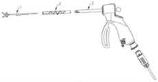
图1a示意性地示出了根据本发明的腔镜手术组件的整体组装结构图;Fig. 1a schematically shows the overall assembly structure diagram of the laparoscopic surgery assembly according to the present invention;
图1b示意性地示出了根据本发明的腔镜手术组件的部分分解结构图;Fig. 1 b schematically shows a partially exploded structural view of a laparoscopic surgery assembly according to the present invention;
图2示出了器械部的示例性结构;Fig. 2 shows the exemplary structure of instrument part;
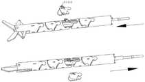
图3示出了蛇骨连接部的示例性结构;Fig. 3 shows the exemplary structure of snake bone connection part;
图4示出了组装状态的蛇骨连接部的结构;Fig. 4 shows the structure of the snake-bone joint in assembled state;
图5示出了蛇骨尾端的示例性结构;Fig. 5 shows the exemplary structure of snake bone tail end;
图6示出了蛇骨的示例性结构;Figure 6 shows an exemplary structure of a snake bone;
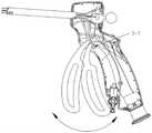
图7示出了蛇骨连接部的摆动范围示意图;Fig. 7 shows a schematic diagram of the swing range of the snake-bone joint;
图8示出了第二摄像头被顶出的示意图;Fig. 8 shows a schematic diagram of the second camera being ejected;
图9示出了器械连接部与蛇骨连接部的配合示意图;Fig. 9 shows a schematic diagram of cooperation between the instrument connection part and the snake bone connection part;
图10示出了手柄结构的分解示意图;Figure 10 shows an exploded schematic view of the handle structure;
图11示出了手柄连接外管的结构图;Fig. 11 shows the structural diagram of the handle connecting the outer tube;
图12示出了手柄拉杆的结构图;Figure 12 shows the structural diagram of the handle pull rod;
图13示出了限位按钮限制击发杆的极限位置的示意图;Fig. 13 shows a schematic diagram of the limit position of the firing rod limited by the limit button;
图14示出了施术器械的其他结构的示意图;和Figure 14 shows a schematic view of other structures of the surgical instrument; and
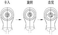
图15和图16示出了蛇骨连接部和手柄安装过程示意图。Fig. 15 and Fig. 16 show the schematic diagrams of the installation process of the snake bone connection part and the handle.
具体实施方式detailed description
下面通过实施例,并结合附图,对本发明的技术方案作进一步详细的说明,但本发明不限于下面的实施例。The technical solution of the present invention will be further described in detail through the following examples in conjunction with the accompanying drawings, but the present invention is not limited to the following examples.
在本申请中,“近端”通常指临近施术者或者操作手柄一侧;而“远端”通常指远离施术者或者操作手柄一侧。In this application, "proximal end" generally refers to the side close to the operator or the operating handle; and "distal end" generally refers to the side away from the operator or the operating handle.
根据本发明的一个实施例,提供一种腔镜手术组件,如图1a和图1b所示。图1a示意性地示出了根据本发明的腔镜手术组件的整体组装结构图,图1b示意性地示出了根据本发明的腔镜手术组件的部分分解结构图。According to one embodiment of the present invention, a laparoscopic surgery assembly is provided, as shown in Fig. 1a and Fig. 1b. Fig. 1a schematically shows the overall assembly structure diagram of the endoscopic surgery assembly according to the present invention, and Fig. 1b schematically shows a partial exploded structure view of the endoscopic surgery assembly according to the present invention.
如图1a和1b所示,根据本发明实施例的腔镜手术组件主要包括.器械部1、.蛇骨连接部2和手柄3。As shown in FIGS. 1a and 1b , the endoscopic surgery assembly according to the embodiment of the present invention mainly includes an
器械部1包括设置在器械部前端的施术器械和与施术器械连接的连接杆,并可滑动地容纳在蛇骨连接部2的内腔中。The
器械部1包括前端的施术器械,用于在人体腔室内执行例如手术操作。根据器械部1的前端的施术器械类型不同,器械部1和蛇骨连接部2可以构成不同组件。施术器械例如包括但不限于剪刀、活检钳、异物钳、锯齿钳。The
根据本发明的一个实施例,器械部1可以包括对应于器械部的钳头1-1,对应于连接杆的拉杆1-3,以及将钳头1-1连接到拉杆1-3的连杆1-2,和设置在拉杆1-3近端用于连接定位的凸台1-4。According to one embodiment of the present invention, the
在此实施例中,连杆1-2包括两个支臂,铰接在拉杆1-3远端,适于操作钳头1-1。当拉杆1-3向远端移动伸出蛇骨连接部的内腔后,推动连杆1-2的两个支臂展开,从而带动钳头1-1张开。In this embodiment, the connecting rod 1-2 includes two arms, hinged at the distal end of the pull rod 1-3, suitable for operating the pliers head 1-1. When the pull rod 1-3 moves to the far end and extends out of the inner cavity of the snake bone joint, the two arms of the connecting rod 1-2 are pushed to expand, thereby driving the pliers head 1-1 to open.
拉杆1-3上设置有弧形凸台1-3-1、导向槽1-3-2。拉杆1-3为半硬材料。如图2所示。The pull rod 1-3 is provided with an arc-shaped boss 1-3-1 and a guide groove 1-3-2. Pull rod 1-3 is semi-hard material. as shown in picture 2.
蛇骨连接部2优选为圆筒形,适于沿着穿刺通道插入人体腔室内。蛇骨连接部2具有设置在远端的的第一摄像头和设置在中部的第二摄像头。The snake-bone connecting part 2 is preferably cylindrical and is suitable for being inserted into a human body cavity along a puncture channel. The snake bone connecting part 2 has a first camera arranged at the far end and a second camera arranged at the middle.
如图3所示,在此实施例中,蛇骨连接部2可以包括蛇骨2-1、摄像头模组2-2和蛇骨线2-3。蛇骨连接部2还可以包括弹簧2-4。As shown in FIG. 3 , in this embodiment, the snake-bone connection part 2 may include a snake-bone 2-1, a camera module 2-2 and a snake-bone wire 2-3. The snake-bone connection part 2 may also include springs 2-4.
蛇骨2-1可以包括第一蛇骨2-1-1、第二蛇骨2-1-2、蛇骨头端2-1-3和蛇骨尾端2-1-4,其中第二蛇骨上切了供第二摄像头2-2-2打开时顶出的槽。在其他实施例中,蛇骨的数量不限于此,可以根据实际需要设置不同数量的蛇骨;供第二摄像头2-2-2打开时顶出的槽也可以设置在其他蛇骨上。The snake bone 2-1 can comprise the first snake bone 2-1-1, the second snake bone 2-1-2, the snake bone end 2-1-3 and the snake bone tail end 2-1-4, wherein the second snake bone Slots are cut in the bone for ejection of the second camera 2-2-2 when opened. In other embodiments, the number of snake bones is not limited thereto, and different numbers of snake bones can be set according to actual needs; the grooves for the second camera 2-2-2 to be ejected when opened can also be set on other snake bones.
摄像头模组2-2可以包括第一摄像头2-2-1、第二摄像头2-2-2和连接线2-2-3。连接线2-2-3将第一摄像头和第二摄像头连接起来便于定位,图3所示的连接线2-2-3是一个示例,其他形式的连接也是可以的。The camera module 2-2 may include a first camera 2-2-1, a second camera 2-2-2 and a connection line 2-2-3. The connection line 2-2-3 connects the first camera and the second camera for easy positioning. The connection line 2-2-3 shown in FIG. 3 is an example, and other forms of connection are also possible.
蛇骨线2-3包括蛇骨线焊接点2-3-1和蛇骨线凸台2-3-2。The snake bone line 2-3 includes the snake bone line welding point 2-3-1 and the snake bone line boss 2-3-2.
进一步的,蛇骨尾端2-1-4上包括连接槽2-1-4-1、卡口2-1-4-2、蛇骨线盲孔2-1-4-3、连接线过孔2-1-4-4和蛇骨头端铆接孔2-1-3-1,见图4。Further, the snake bone tail end 2-1-4 includes a connection groove 2-1-4-1, a bayonet socket 2-1-4-2, a snake bone wire blind hole 2-1-4-3, a connecting wire through Hole 2-1-4-4 and snake head riveting hole 2-1-3-1 are shown in Fig. 4.
弹簧2-4置于蛇骨尾端2-1-4内,用于蛇骨线凸台2-3-2的限位。Spring 2-4 is placed in snake bone tail end 2-1-4, and is used for the limit of snake bone line boss 2-3-2.
图5、图6示出了蛇骨连接部2的各部分的组装示意图。。5 and 6 show schematic diagrams of assembly of various parts of the snake-bone connection part 2 . .
蛇骨线2-3的一端2-3-1焊接于蛇骨头端2-1-3,另一端蛇骨线凸台2-3-2与弹簧2-4在连接槽2-1-4-1中相抵。蛇骨线2-3的中间部分穿过各个蛇骨上的定位特征,例如定位孔,并可以通过焊接或其他方式进行固定,以将蛇骨连接部2的各个部分组装起来。One end 2-3-1 of the snake bone line 2-3 is welded to the snake bone end 2-1-3, and the other end snake bone line boss 2-3-2 and the spring 2-4 are in the connecting groove 2-1-4- 1 in offset. The middle part of the snake wire 2-3 passes through the positioning features on each snake, such as positioning holes, and can be fixed by welding or other methods to assemble the various parts of the snake connecting part 2.
所述第二蛇骨2-1-2包括内凹弧槽面2-1-2-1、外突弧面2-1-2-3和摄像头切割面2-1-2-2。摄像头切割面2-1-2-2例如为三边切割,形成可以被顶起的膜片。蛇骨的材料具有弹性,因此摄像头切割面2-1-2-2顶起后具有一定回弹性,撤销顶出力后会恢复初始位置。The second snake bone 2-1-2 includes an inner concave arc groove surface 2-1-2-1, an outer convex arc surface 2-1-2-3 and a camera cutting surface 2-1-2-2. The cutting surface 2-1-2-2 of the camera is, for example, cut on three sides, forming a diaphragm that can be lifted. The material of the snake bone is elastic, so the cutting surface 2-1-2-2 of the camera has a certain degree of resilience after jacking up, and will return to the original position after canceling the jacking force.
具体而言,将第二蛇骨2-1-2上一个完整的弧面,切割出冂字形的痕迹,保留一侧不切割,这样的切割方式可以使得摄像头被顶出时蛇骨切割面随之变形打开让摄像头出现在蛇骨外面。同时由于还有一个边没被切割,且由于应力的存在,当摄像头不再受到顶出力作用时,蛇骨被切割出的部分就会在回弹力作用下回到初始位置,同时将摄像头压回到蛇骨管内部,恢复到摄像头被顶出前的位置。Specifically, a complete curved surface on the second snake bone 2-1-2 is cut into a zigzag trace, and one side is left uncut. This cutting method can make the snake bone cutting surface follow the camera when the camera is pushed out. The deformation is turned on so that the camera appears outside the snake bone. At the same time, because there is still a side that has not been cut, and due to the existence of stress, when the camera is no longer subjected to the ejection force, the cut part of the snake bone will return to the original position under the action of the rebound force, and the camera will be pressed back at the same time. Go inside the snake bone tube and restore to the position before the camera was ejected.
第一蛇骨2-1-1结构除了没有摄像头切割面2-1-2-2外,其他结构与第二蛇骨2-1-2一致,见图6。The structure of the first snake bone 2-1-1 is the same as that of the second snake bone 2-1-2 except that there is no camera cutting surface 2-1-2-2, as shown in FIG. 6 .
蛇骨头端和蛇骨尾端与各个蛇骨相邻的部分也可以形成对应的内凹弧槽面和外突弧面。The parts adjacent to the snake bones at the end of the snake bone and the tail end of the snake bone can also form corresponding concave arc groove surfaces and outwardly protruding arc surfaces.
蛇骨连接部2的各蛇骨、蛇骨头端和蛇骨尾端之间相邻的内凹弧槽面与外突弧面相配合,使得蛇骨节直接可以发生相对转动,从而整个蛇骨连接部2可以一定范围内任意角度摆动,见图7。The adjacent concave arc groove surfaces between the snake bones, the snake head end and the snake bone tail end of the snake bone joint 2 cooperate with the outwardly protruding arc surface, so that the snake joints can directly rotate relative to each other, so that the entire snake bone joint 2 can swing at any angle within a certain range, see Figure 7.
在组装状态下,所述连接线2-2-3通过连接线过孔2-1-4-4穿过蛇骨尾端2-1-4,使得第二摄像头2-2-2放置在摄像头切割面2-1-2-2相对应的位置,见图8。组装到位后,所述连接线2-2-3可以相对于蛇骨尾端2-1-4固定,以使得摄像头在蛇骨连接部2中的位置相对固定。In the assembled state, the connecting wire 2-2-3 passes through the connecting wire via hole 2-1-4-4 through the tail end 2-1-4 of the snake bone, so that the second camera 2-2-2 is placed on the camera See Figure 8 for the position corresponding to the cutting surface 2-1-2-2. After being assembled in place, the connection wire 2-2-3 can be fixed relative to the tail end 2-1-4 of the snake bone, so that the position of the camera in the snake bone connection part 2 is relatively fixed.
当拉杆1-3向前运动时,弧形凸台1-3-1将第二摄像头2-2-2向外顶起,同时摄像头切割面2-1-2-2被第二摄像头2-2-2顶起,第二摄像头2-2-2伸出蛇骨连接部。当拉杆1-3向后运动时,弧形凸台1-3-1不再对第二摄像头2-2-2起到支撑作用,第二摄像头2-2-2在摄像头切割面2-1-2-2的作用力下回到蛇骨连接部内部。When the pull rod 1-3 moves forward, the arc-shaped boss 1-3-1 pushes the second camera 2-2-2 outward, and at the same time, the cutting surface 2-1-2-2 of the camera is captured by the second camera 2-2-2. 2-2 lifts up, and the second camera 2-2-2 protrudes from the connecting part of the snake bone. When the pull bar 1-3 moves backward, the arc-shaped boss 1-3-1 no longer plays a supporting role for the second camera 2-2-2, and the second camera 2-2-2 is on the camera cutting surface 2-1. Return to the inside of the snake bone joint under the force of -2-2.
弧形凸台1-3-1形成有弧形面,以将第二摄像头2-2-2平稳地顶出去。弧形凸台1-3-1突出拉杆1-3的高度进行适当设置,以使得第二摄像头2-2-2能够顶出蛇骨连接部2的内腔到适当的高度,形成适当的视角。The arc-shaped boss 1-3-1 is formed with an arc-shaped surface to push out the second camera 2-2-2 smoothly. The height of the arc-shaped boss 1-3-1 protruding from the tie rod 1-3 is properly set so that the second camera 2-2-2 can push out of the inner cavity of the snake bone connection part 2 to an appropriate height to form an appropriate viewing angle .
拉杆1-3形成有导向槽1-3-2,如图2所示。导向槽1-3-2例如可以由沿着弧形凸台1-3-1两侧设置的侧壁构成,使得无论拉杆1-3前进或后退第二摄像头2-2-2始终在导向槽1-3-2内运动,如图9所示。第二摄像头2-2-2始终在导向槽1-3-2内运动可以确保第二摄像头2-2-2的周向位置基本固定,从而能够顺利地从摄像头切割面2-1-2-2处顶出去。弧形凸台1-3-1位于导向槽1-3-2的中间位置。The pull rod 1-3 is formed with a guide groove 1-3-2, as shown in FIG. 2 . The guide groove 1-3-2, for example, can be formed by side walls arranged along both sides of the arc-shaped boss 1-3-1, so that the second camera 2-2-2 is always in the guide groove no matter whether the pull rod 1-3 advances or retreats. 1-3-2 internal movement, as shown in Figure 9. The second camera 2-2-2 always moves in the guide groove 1-3-2 to ensure that the circumferential position of the second camera 2-2-2 is basically fixed, so that it can smoothly cut from the camera cutting surface 2-1-2- 2 jacks out. The arc-shaped boss 1-3-1 is located in the middle of the guide groove 1-3-2.
如图10所示,手柄3主要包括如下部分:As shown in Figure 10, the
手柄连接外管3-1、手柄拉杆3-2、弹簧3-3、万向节拉绳3-4、万向节3-5、连杆3-6、限位按钮3-7、击发杆3-8、手柄右壳3-9、手柄左壳3-10、数据连接线3-11、管路3-12、鲁尔组件3-13、数据线插座3-14和外部数据线插头3-15。The handle is connected to the outer tube 3-1, the handle rod 3-2, the spring 3-3, the pull cord of the universal joint 3-4, the universal joint 3-5, the connecting rod 3-6, the limit button 3-7, and the firing rod 3-8, handle right shell 3-9, handle left shell 3-10, data connection line 3-11, pipeline 3-12, Luer assembly 3-13, data line socket 3-14 and external data line plug 3 -15.
手柄连接外管3-1如图11所示,其中部分3-1-8用于放置手柄拉杆3-2及连接后的器械部的凸台1-4。手柄连接外管3-1包括定位槽3-1-1,开口3-1-3和3-1-2分别连接腔体3-1-4和3-1-5,腔体3-1-4和3-1-5连接管路3-12用于通入/排除外界气体或液体。通孔3-1-6安装万向节拉绳3-4,弹簧3-3也安装在前端3-1-6,用于万向节拉绳3-4的限位。数据线通孔3-1-7用于通过数据线,卡口3-1-9用于卡接卡口2-1-4-2。The handle is connected to the outer tube 3-1 as shown in Figure 11, wherein the part 3-1-8 is used to place the handle rod 3-2 and the boss 1-4 of the connected instrument part. The handle is connected to the outer tube 3-1 and includes a positioning groove 3-1-1, the openings 3-1-3 and 3-1-2 are respectively connected to the cavity 3-1-4 and 3-1-5, and the cavity 3-1- 4 and 3-1-5 are connected to pipeline 3-12 for introducing/expelling external gas or liquid. Universal joint stay cord 3-4 is installed in through hole 3-1-6, and spring 3-3 is also installed in front end 3-1-6, and is used for the spacing of universal joint stay cord 3-4. The data line through hole 3-1-7 is used for passing the data line, and the bayonet 3-1-9 is used for snapping into the bayonet 2-1-4-2.
万向节拉绳3-4在手柄3与蛇骨连接部2装配后拉动蛇骨线凸台2-3-2。万向节与万向节拉绳固定连接,固定方式包括但不限于胶水连接,塑胶熔接包覆等。万向节固定在手柄上,可以是一体模具成型,可以是螺丝紧固。蛇骨连接部2通过卡口2-1-4-2旋转后装备固定在手柄上。The universal joint stay rope 3-4 pulls the snake bone line boss 2-3-2 after the
手柄拉杆3-2结构如图12所示。The structure of the handle rod 3-2 is shown in Figure 12.
手柄拉杆3-2包括定位凸台3-2-1,配合定位槽3-1-1定位。槽口3-2-3用于避让器械部的插入,弧形槽3-2-2用于连接旋转后的凸台1-4。孔口3-2-4用于连接连接杆3-6。The handle pull rod 3-2 includes a positioning boss 3-2-1, which cooperates with the positioning slot 3-1-1 for positioning. The notch 3-2-3 is used to avoid the insertion of the instrument part, and the arc-shaped groove 3-2-2 is used to connect the rotated boss 1-4. The orifice 3-2-4 is used to connect the connecting rod 3-6.
手柄拉杆3-2还包括连杆结构3-6。当转动击发杆3-8时,控制手柄拉杆3-2前后移动,从而通过凸台1-4带动拉杆1-3前后运动,由此控制器械部前端施术器械的开合。限位按钮3-7用于限制击发杆3-8的极限位置,如图13所示。The handle rod 3-2 also includes a connecting rod structure 3-6. When rotating the firing rod 3-8, the control handle pull rod 3-2 moves back and forth, thereby driving the pull rod 1-3 to move back and forth by the boss 1-4, thereby controlling the opening and closing of the front end of the instrument portion. The limit button 3-7 is used to limit the extreme position of the firing rod 3-8, as shown in FIG. 13 .
施术器械除了剪刀形式,还有锯齿钳等多种结构,如图14所示。图14是锯齿钳的示意图,作用是夹取息肉用于活检或夹取异物。它的结构与剪刀形式类似,都是通过四杆机构在拉杆1-3的作用下发生相对运动,起到啮合的运动效果。而该啮合运动发生在剪刀片上就呈现出剪切的效果,发生在锯齿钳上就呈现夹取的效果。In addition to the form of scissors, surgical instruments also have various structures such as serrated forceps, as shown in Figure 14. Fig. 14 is a schematic diagram of the serrated forceps, which are used to capture polyps for biopsy or foreign bodies. Its structure is similar to that of scissors, all of which move relative to each other under the action of the pull rods 1-3 through the four-bar mechanism to achieve the effect of meshing motion. However, when the meshing movement occurs on the scissor blades, it will present the effect of shearing, and if it occurs on the serrated pliers, it will present the effect of clamping.
图15和图16描述蛇骨连接部和器械手柄的旋转安装过程。Figures 15 and 16 describe the rotational installation process of the serpentine joint and instrument handle.
将需要使用的器械组件(器械部和蛇骨连接部)和手柄安装到一起,具体的,先将数据线2-2-3与数据连接线3-11相接,万向节拉绳3-4插入连接槽2-1-4-1中,在对准卡口2-1-4-2和卡口3-1-9,旋转卡入后完成组装。蛇骨线凸台2-3-2和万向节拉绳3-4在旋转安装后得以通过凸台连接。Install the instrument components (instrument part and snake bone connection part) and the handle to be used together. Specifically, first connect the data line 2-2-3 to the data connection line 3-11, and the universal joint pull cord 3- 4 Insert it into the connection slot 2-1-4-1, align the bayonet 2-1-4-2 and the bayonet 3-1-9, and rotate to snap in to complete the assembly. Snake bone line boss 2-3-2 and universal joint stay cord 3-4 can be connected by boss after being installed in rotation.
击发手柄3-8即可控制施术器械的开合。The opening and closing of the surgical instrument can be controlled by firing the handle 3-8.
实际使用时,组装完成后先测试手柄与施术器械的连接是否正常,反复击发手柄观察施术器械头部的开合,确认连接正常后将施术器械在闭合状态下通过病患通道到达病灶,缓慢击发手柄。此时第二摄像头升起,按下限位按钮3-7,对击发杆3-8限位,击发杆倒退回限位后被限制后退,此时第二摄像头不会因为击发杆的后退而下降。用拇指转动万向节3-5,万向节拉绳可以控制蛇骨连接部在一定角度内任意方向随着万向球头偏摆,从而直观方便的控制器械和摄像头角度。In actual use, after the assembly is completed, first test whether the connection between the handle and the surgical instrument is normal, and repeatedly fire the handle to observe the opening and closing of the surgical instrument head. After confirming that the connection is normal, the surgical instrument will pass through the patient’s channel to the lesion in the closed state , fire the handle slowly. At this time, the second camera rises, press the limit button 3-7, limit the firing rod 3-8, and the firing rod retreats back to the limit position and is restricted to move backward. At this time, the second camera will not fall due to the retreat of the firing rod . Use the thumb to turn the universal joint 3-5, and the universal joint pull cord can control the snake joint to swing along with the universal ball head in any direction within a certain angle, so as to intuitively and conveniently control the angle of the instrument and the camera.
完成施术器械操作后反向打开限位按钮3-7,击发杆3-8可以继续后退使得摄像头2下降退回蛇骨连接部的内腔中。将施术器械缩回且摄像头2退回后,撤出器械。如果有必要,可以更换器械组件后再次进入病灶部分手术,或者直接结束手术。After completing the operation of the operating instrument, the limit button 3-7 is reversely opened, and the firing rod 3-8 can continue to retreat so that the camera 2 descends and returns to the inner cavity of the snake bone joint. After the operating instrument is retracted and the camera 2 is retracted, the instrument is withdrawn. If necessary, the instrument components can be replaced and the lesion part can be operated again, or the operation can be ended directly.
根据本发明的腔镜手术组件具有如下优点。The laparoscopic surgery assembly according to the present invention has the following advantages.
1.双摄像头的设计利于医生判断距离;且第二摄像头在进入病人体内后打开,进出病人身体时不需要增大通道尺寸。第一摄像头可以观察进出时的状态,更加安全,降低了风险。第一摄像头和第二摄像头不同的位置可以分别多屏观察病患体内状况:病灶形态、器械形态以及病灶和器械之间的形态。第二摄像头和器械刃口呈特定角度(例如30-60度),可以观察到刃口的切割状态。1. The design of dual cameras is beneficial for doctors to judge the distance; and the second camera is opened after entering the patient's body, and there is no need to increase the channel size when entering and exiting the patient's body. The first camera can observe the state when entering and exiting, which is safer and reduces risks. The different positions of the first camera and the second camera can observe the patient's internal conditions on multiple screens: the shape of the lesion, the shape of the device, and the shape between the focus and the device. The second camera is at a specific angle (for example, 30-60 degrees) with the cutting edge of the instrument, and the cutting state of the cutting edge can be observed.
2.蛇骨连接部和万向手柄结合可以更加直观的操作器械角度,不需要双手操作,增加的医生操作的便捷性。2. The combination of the snake bone connection part and the universal handle can operate the angle of the instrument more intuitively, without the need for two-handed operation, which increases the convenience of the doctor's operation.
3.手柄连接外管上有连接外部的进出腔道,包括但不限于可以用于腹腔镜的换气排烟和宫腔镜的通液循环。由于器械不再单独占用腔镜通道,同规格尺寸下拥有更大的通液管径,流量更大。3. The handle is connected to the outer tube with an in-out cavity connected to the outside, including but not limited to ventilation and smoke exhaust for laparoscopy and liquid circulation for hysteroscopy. Since the instrument no longer occupies the channel of the endoscope alone, it has a larger liquid diameter and a greater flow rate under the same size.
4.器械组件及手柄为分体结构,提升了组件可选性,同一台手术不再需要多个器械,降低了手术成本,且器械组件和手柄可以分别灭菌,灭菌效率和效果优于一体式器械。4. The instrument components and the handle are split structures, which improves the optionality of the components. The same operation does not need multiple instruments, which reduces the operation cost, and the instrument components and the handle can be sterilized separately, and the sterilization efficiency and effect are better than All-in-one device.
5.器械组件可以作为一次性器械使用,降低了医疗成本和交叉感染风险。5. Device components can be used as disposable devices, reducing medical costs and cross-infection risks.
本发明的实施方式并不限于上述实施例所述,在不偏离本发明的精神和范围的情况下,本领域普通技术人员可以在形式和细节上对本发明做出各种改变和改进,而这些均被认为落入了本发明的保护范围。The embodiments of the present invention are not limited to the above-mentioned embodiments. Without departing from the spirit and scope of the present invention, those skilled in the art can make various changes and improvements to the present invention in form and details, and these All are considered to fall into the protection scope of the present invention.
Claims (15)
Priority Applications (1)
| Application Number | Priority Date | Filing Date | Title |
|---|---|---|---|
| CN202211414109.0ACN115530726A (en) | 2022-11-11 | 2022-11-11 | Laparoscopic surgery subassembly |
Applications Claiming Priority (1)
| Application Number | Priority Date | Filing Date | Title |
|---|---|---|---|
| CN202211414109.0ACN115530726A (en) | 2022-11-11 | 2022-11-11 | Laparoscopic surgery subassembly |
Publications (1)
| Publication Number | Publication Date |
|---|---|
| CN115530726Atrue CN115530726A (en) | 2022-12-30 |
Family
ID=84721287
Family Applications (1)
| Application Number | Title | Priority Date | Filing Date |
|---|---|---|---|
| CN202211414109.0APendingCN115530726A (en) | 2022-11-11 | 2022-11-11 | Laparoscopic surgery subassembly |
Country Status (1)
| Country | Link |
|---|---|
| CN (1) | CN115530726A (en) |
Citations (14)
| Publication number | Priority date | Publication date | Assignee | Title |
|---|---|---|---|---|
| US5312391A (en)* | 1992-07-29 | 1994-05-17 | Wilk Peter J | Laparoscopic instrument assembly |
| US5330486A (en)* | 1992-07-29 | 1994-07-19 | Wilk Peter J | Laparoscopic or endoscopic anastomosis technique and associated instruments |
| CN101238967A (en)* | 2007-02-09 | 2008-08-13 | 奥林巴斯医疗株式会社 | Actuator device, camera device and endoscope device |
| CN201299552Y (en)* | 2008-10-10 | 2009-09-02 | 广州宝胆医疗器械科技有限公司 | Hard primary/secondary cholecystoscope and cystic duct scope system |
| CN104546113A (en)* | 2014-12-30 | 2015-04-29 | 上海交通大学 | Handheld turning and expanding single-port laparoscope |
| CN104586347A (en)* | 2015-01-30 | 2015-05-06 | 西安交通大学医学院第一附属医院 | Appendix primary-secondary endoscope |
| CN105246393A (en)* | 2013-03-28 | 2016-01-13 | 恩多巧爱思股份有限公司 | Compact multi-viewing element endoscopy system |
| CN106264626A (en)* | 2016-08-27 | 2017-01-04 | 天津大学 | A minimally invasive surgical device based on natural orifice |
| US20180028217A1 (en)* | 2015-02-02 | 2018-02-01 | Tandem Technologies Ltd. | Probe for tissue treatment with a tandem snare |
| CN109602381A (en)* | 2018-12-27 | 2019-04-12 | 上海交通大学医学院附属瑞金医院 | A modular in vivo 3D miniature camera that simulates the human eye |
| CN209661594U (en)* | 2018-12-27 | 2019-11-22 | 上海交通大学医学院附属瑞金医院 | A kind of 3D miniature webcam of the interior simulation human eye of modularization body |
| CN210300932U (en)* | 2019-03-29 | 2020-04-14 | 佛山市柯诺医疗器械有限公司 | Oral cavity endoscope with double cameras |
| CN215078308U (en)* | 2021-01-15 | 2021-12-10 | 杨廷旭 | Intestinal primary and secondary mirror for operation |
| CN115251809A (en)* | 2022-09-28 | 2022-11-01 | 科弛医疗科技(北京)有限公司 | Endoscope with a detachable handle |
- 2022
- 2022-11-11CNCN202211414109.0Apatent/CN115530726A/enactivePending
Patent Citations (14)
| Publication number | Priority date | Publication date | Assignee | Title |
|---|---|---|---|---|
| US5312391A (en)* | 1992-07-29 | 1994-05-17 | Wilk Peter J | Laparoscopic instrument assembly |
| US5330486A (en)* | 1992-07-29 | 1994-07-19 | Wilk Peter J | Laparoscopic or endoscopic anastomosis technique and associated instruments |
| CN101238967A (en)* | 2007-02-09 | 2008-08-13 | 奥林巴斯医疗株式会社 | Actuator device, camera device and endoscope device |
| CN201299552Y (en)* | 2008-10-10 | 2009-09-02 | 广州宝胆医疗器械科技有限公司 | Hard primary/secondary cholecystoscope and cystic duct scope system |
| CN105246393A (en)* | 2013-03-28 | 2016-01-13 | 恩多巧爱思股份有限公司 | Compact multi-viewing element endoscopy system |
| CN104546113A (en)* | 2014-12-30 | 2015-04-29 | 上海交通大学 | Handheld turning and expanding single-port laparoscope |
| CN104586347A (en)* | 2015-01-30 | 2015-05-06 | 西安交通大学医学院第一附属医院 | Appendix primary-secondary endoscope |
| US20180028217A1 (en)* | 2015-02-02 | 2018-02-01 | Tandem Technologies Ltd. | Probe for tissue treatment with a tandem snare |
| CN106264626A (en)* | 2016-08-27 | 2017-01-04 | 天津大学 | A minimally invasive surgical device based on natural orifice |
| CN109602381A (en)* | 2018-12-27 | 2019-04-12 | 上海交通大学医学院附属瑞金医院 | A modular in vivo 3D miniature camera that simulates the human eye |
| CN209661594U (en)* | 2018-12-27 | 2019-11-22 | 上海交通大学医学院附属瑞金医院 | A kind of 3D miniature webcam of the interior simulation human eye of modularization body |
| CN210300932U (en)* | 2019-03-29 | 2020-04-14 | 佛山市柯诺医疗器械有限公司 | Oral cavity endoscope with double cameras |
| CN215078308U (en)* | 2021-01-15 | 2021-12-10 | 杨廷旭 | Intestinal primary and secondary mirror for operation |
| CN115251809A (en)* | 2022-09-28 | 2022-11-01 | 科弛医疗科技(北京)有限公司 | Endoscope with a detachable handle |
Similar Documents
| Publication | Publication Date | Title |
|---|---|---|
| EP2443988B1 (en) | Endoscope wiper blade cleaner | |
| US10918365B2 (en) | Medical retrieval systems and related methods | |
| EP1935354B1 (en) | Surgical treatment apparatus | |
| JP5407036B2 (en) | Treatment endoscope | |
| JP5226897B2 (en) | Rigid endoscope | |
| US9993233B2 (en) | Large capacity biopsy forceps | |
| US20110112517A1 (en) | Surgical instrument | |
| JP7486267B2 (en) | Insertable robots for minimally invasive surgery | |
| JP6290376B2 (en) | Surgeon-controlled endoscopic device | |
| WO2012078461A1 (en) | Instrument control device | |
| US20240215807A1 (en) | Medical systems, devices, and related methods | |
| CA3177354A1 (en) | Medical systems, devices, and related methods | |
| CN118830798B (en) | Front end structure and endoscope | |
| EP4117502A1 (en) | Endoscope devices comprising a moveable camera | |
| CN114096187B (en) | Portable endoscope with disposable steerable cannula | |
| CN115530726A (en) | Laparoscopic surgery subassembly | |
| JP2024161175A (en) | Endoscopic tool stabilization and related methods of use - Patents.com | |
| JP6028136B1 (en) | Endoscope | |
| JP2003310629A (en) | Surgical tools | |
| CN114732449A (en) | Rigid joint structure of instrument rod and a surgical method | |
| JP2018504995A (en) | Surgical assembly and method of use | |
| CN116035708B (en) | a surgical instrument | |
| CN220938097U (en) | Intestinal canal supporting device for medical treatment | |
| US11571232B2 (en) | Corkscrew tissue resecting device | |
| US20200289201A1 (en) | Flexible articulating surgical probe |
Legal Events
| Date | Code | Title | Description |
|---|---|---|---|
| PB01 | Publication | ||
| PB01 | Publication | ||
| SE01 | Entry into force of request for substantive examination | ||
| SE01 | Entry into force of request for substantive examination |