CN115524178A - Continuous sampling device of oil smoke - Google Patents
Continuous sampling device of oil smokeDownload PDFInfo
- Publication number
- CN115524178A CN115524178ACN202211223899.4ACN202211223899ACN115524178ACN 115524178 ACN115524178 ACN 115524178ACN 202211223899 ACN202211223899 ACN 202211223899ACN 115524178 ACN115524178 ACN 115524178A
- Authority
- CN
- China
- Prior art keywords
- sampling
- pipe
- tube
- cylinder
- connecting pipe
- Prior art date
- Legal status (The legal status is an assumption and is not a legal conclusion. Google has not performed a legal analysis and makes no representation as to the accuracy of the status listed.)
- Pending
Links
Images


Classifications
- G—PHYSICS
- G01—MEASURING; TESTING
- G01N—INVESTIGATING OR ANALYSING MATERIALS BY DETERMINING THEIR CHEMICAL OR PHYSICAL PROPERTIES
- G01N1/00—Sampling; Preparing specimens for investigation
- G01N1/02—Devices for withdrawing samples
- G01N1/22—Devices for withdrawing samples in the gaseous state
- G01N1/2247—Sampling from a flowing stream of gas
- G01N1/2258—Sampling from a flowing stream of gas in a stack or chimney
Landscapes
- Health & Medical Sciences (AREA)
- Life Sciences & Earth Sciences (AREA)
- Engineering & Computer Science (AREA)
- Biomedical Technology (AREA)
- Molecular Biology (AREA)
- Physics & Mathematics (AREA)
- Chemical & Material Sciences (AREA)
- Analytical Chemistry (AREA)
- Biochemistry (AREA)
- General Health & Medical Sciences (AREA)
- General Physics & Mathematics (AREA)
- Immunology (AREA)
- Pathology (AREA)
- Sampling And Sample Adjustment (AREA)
Abstract
Translated fromChinese
Description
Translated fromChinese技术领域technical field
本发明涉及油烟检测领域,具体为一种油烟连续采样装置。The invention relates to the field of oil fume detection, in particular to a continuous oil fume sampling device.
背景技术Background technique
油烟检测是为了测定排放油烟气体中颗粒物、有害物质的含量,以确定油烟是否符合排放标准,现有技术中采用延伸至油烟管道中的监测探头用于检测油烟中物质含量,此方法使监测探头位于环境较为恶劣的油烟管道内,导致监测探头寿命较短,另一中采用采样的方式,使部分油烟进入特定管道以满足监测要求。Oil fume detection is to measure the content of particles and harmful substances in the exhaust fume gas, so as to determine whether the oil fume meets the emission standards. In the prior art, a monitoring probe extending into the oil fume pipeline is used to detect the content of substances in the oil fume. This method makes the monitoring probe It is located in the oil fume pipeline with a relatively harsh environment, resulting in a short life of the monitoring probe. The other adopts a sampling method to allow part of the oil fume to enter the specific pipeline to meet the monitoring requirements.
如专利号为CN211825554U的申请文件公开了一种用于净化器排烟管前端的油烟检测平衡采样系统,包括导烟管和连通设置于导烟管上的平衡采样箱;导烟管的两端分别与排烟管连通,且导烟管内设置有对其内导流的油烟进行缓冲的油烟缓冲物;平衡采样箱上安装有油烟检测探头,油烟检测探头的探头前段伸入平衡采样箱中;排烟管内导流的油烟冲击进入导烟管并可通过导烟管导入平衡采样箱内。本实用新型提供的一种用于净化器排烟管前端的油烟检测平衡采样系统,能够将排烟管内的油烟引入平衡采样箱内再进行检测,改善检测环境,避免油烟检测探头被排烟管内的恶劣环境以及油烟冲击而损坏,提高检测精度。For example, the application document whose patent number is CN211825554U discloses a kind of oil fume detection balanced sampling system for the front end of the smoke exhaust pipe of the purifier, including a smoke guide pipe and a balanced sampling box connected to the smoke guide pipe; the two ends of the smoke guide pipe They are respectively connected with the smoke exhaust pipe, and the smoke guide pipe is provided with a soot buffer for buffering the oil fume diverted in it; the oil fume detection probe is installed on the balanced sampling box, and the front part of the probe of the oil fume detection probe extends into the balanced sampling box; The oil fume diverted in the smoke exhaust pipe impacts into the smoke guide pipe and can be introduced into the balanced sampling box through the smoke guide pipe. The utility model provides an oil fume detection balanced sampling system for the front end of the exhaust pipe of the purifier, which can introduce the oil fume in the exhaust pipe into a balanced sampling box for detection, improve the detection environment, and prevent the oil fume detection probe from being trapped in the exhaust pipe. The harsh environment and the impact of oil fume will damage it, and improve the detection accuracy.
再如专利号为CN108414386B的申请文件公开了一种免清洗颗粒物浓度的采样设备。该免清洗颗粒物浓度的采样设备包括采样装置和采样枪,采样枪的采样枪接口连接采样装置的出口;采样装置包括第一半壳、第二半壳和油烟滤芯;油烟滤芯位于第一半壳与第二半壳形成的空腔内;油烟滤芯包括第一膜结构和第二膜结构;采样装置的入口设置在第一半壳,其出口设置在第二半壳;第一膜结构包括聚丙烯纤维滤膜或者聚四氟乙烯膜;第二膜结构包括玻璃纤维滤膜。本发明的目的在于提供免清洗颗粒物浓度的采样设备,具有免清洗、易使用、操作简便等优点,且对油烟类的颗粒物浓度的采样、测试更加的科学和准确。Another example is that the application document with the patent number CN108414386B discloses a sampling device for no-cleaning particle concentration. The sampling equipment for the concentration of no-clean particulate matter includes a sampling device and a sampling gun, and the sampling gun interface of the sampling gun is connected to the outlet of the sampling device; the sampling device includes a first half shell, a second half shell and an oil fume filter element; the oil fume filter element is located in the first half shell In the cavity formed with the second half shell; the oil fume filter element includes a first membrane structure and a second membrane structure; the inlet of the sampling device is set in the first half shell, and its outlet is set in the second half shell; the first membrane structure includes poly Acrylic fiber filter membrane or polytetrafluoroethylene membrane; the second membrane structure includes glass fiber filter membrane. The object of the present invention is to provide a no-cleaning particulate concentration sampling device, which has the advantages of no-cleaning, easy to use, and simple operation, and more scientific and accurate sampling and testing of the concentration of soot particulate matter.
但是颗粒物以及其他有害物质在油烟中做布朗运动,无论是监测探头延伸至油烟管道内、还是采用上述取样检测的方式,采样区域单一、样本容量较小,仅反应部分区域油烟中污染物含量,反应数据不准确。However, particles and other harmful substances do Brownian motion in the oil fume. Whether the monitoring probe is extended into the oil fume pipe or the above-mentioned sampling detection method is used, the sampling area is single and the sample volume is small, which only reflects the pollutant content in the oil fume in some areas. Response data is inaccurate.
发明内容Contents of the invention
本发明的目的在于提供一种油烟连续采样装置,以解决上述背景技术中提出的问题。The object of the present invention is to provide a continuous sampling device for oily fumes to solve the problems raised in the above-mentioned background technology.
为实现上述目的,本发明提供如下技术方案:To achieve the above object, the present invention provides the following technical solutions:
一种油烟连续采样装置,包括采样管,所述采样管内端与采样轮连接,采样管外端与监测探头连接,采样轮包括与采样管固定连接且连通的轮盘,轮盘侧面与连管转动连接且连通,连管上连接有线性阵列的采样筒,采样筒与连管连通,所述采样管与监测探头连接处连接回流管,采样管连接轮盘的方式连接连管,并于连管上连接采用筒,能够多方位采集样本,扩充样本含量,从而测得到相对较为准确的污染物含量数值。A continuous oil fume sampling device, comprising a sampling tube, the inner end of the sampling tube is connected to a sampling wheel, and the outer end of the sampling tube is connected to a monitoring probe. Rotationally connected and communicated, the connecting pipe is connected with a linear array of sampling cylinders, the sampling cylinder is connected to the connecting pipe, the connection between the sampling pipe and the monitoring probe is connected to the return pipe, the sampling pipe is connected to the connecting pipe in the form of a roulette, and connected to the connecting pipe. The connection on the pipe adopts a cylinder, which can collect samples in multiple directions and expand the sample content, so as to obtain relatively accurate pollutant content values.
优选的,所述采样筒为棱台状,采样筒侧面与水平面倾斜,采样筒中部与采样管连通,采用筒设置为棱台状并且侧面倾斜在油烟气流的冲击下能够转动,从而实现多点位采集。Preferably, the sampling cylinder is in the shape of a prism, the side of the sampling cylinder is inclined to the horizontal plane, and the middle part of the sampling cylinder is connected to the sampling pipe. The cylinder is set in the shape of a prism and the side is inclined to be able to rotate under the impact of the oil fume flow, thereby realizing multi-point bit acquisition.
优选的,所述连管包括多段依次转动连接的分管,相邻分管之间通过弹簧管连接,每个分管中部对应连接采样筒,连管采用多个分管依次通过弹簧管连接的方式,使连管可弯曲进而改变连管外端与轮盘之间的距离,适用于不同直径的排烟管道。Preferably, the connecting pipe includes a plurality of sub-pipes which are sequentially rotated and connected, and the adjacent sub-pipes are connected by spring tubes, and the middle part of each sub-pipe is correspondingly connected to the sampling cylinder. The pipe can be bent to change the distance between the outer end of the connecting pipe and the wheel, and is suitable for smoke exhaust pipes with different diameters.
优选的,所述弹簧管包括连接于两个相邻分管支架的软管,软管内部连接支撑弹簧,支撑弹簧两端连接两个相邻分管之间,相邻分管外侧通过销轴转动连接,弹簧管采用软管内部连接支撑弹簧的方式使相邻分管之间能够保持连通,在连管外端不受到压力的情况下可处于自然伸直状态,以覆盖较大的面积。Preferably, the spring tube includes a hose connected to two adjacent sub-pipe brackets, the hose is internally connected to a support spring, both ends of the support spring are connected between two adjacent sub-pipes, and the outer sides of the adjacent sub-pipes are rotatably connected, The spring tube adopts the method of connecting the support spring inside the hose so that the adjacent branch tubes can maintain communication. When the outer end of the connecting tube is not under pressure, it can be in a natural straightening state to cover a larger area.
优选的,所述轮盘包括多个同轴转动连接的转环,每个转环侧面对应连接一个连管,连管与转环内部连通,轮盘为多个转环同轴转动连接,使连管相对于轮盘能够转动,进而改变连管与采样管之间的夹角,便于取出或插入连管。Preferably, the roulette includes a plurality of swivels that are coaxially rotatably connected, each side of the rotatable ring is connected to a connecting pipe, and the connecting pipe communicates with the inside of the rotatable ring, and the roulette is connected by a plurality of swivel rings that are coaxially rotatable, so that The connecting tube can rotate relative to the wheel, thereby changing the angle between the connecting tube and the sampling tube, so as to facilitate the removal or insertion of the connecting tube.
优选的,所述采样管包括两个平行的导向管,两个导向管之间固定连接轴柱,轴柱侧面设置有环槽,所述转环位于环槽内,在两个导向管之间设置轴柱用于连接转环,使转环能够以轴柱轴线为中心转动,进而使多个连管转动至与采集管平齐的位置。Preferably, the sampling tube includes two parallel guide tubes, the two guide tubes are fixedly connected to the shaft column, and the side of the shaft column is provided with a ring groove, and the swivel is located in the ring groove, between the two guide tubes The shaft column is used to connect the swivel ring, so that the swivel ring can rotate around the axis of the shaft column, and then the plurality of connecting pipes can be rotated to a position flush with the collection tube.
优选的,两个所述导向管截面为矩形,两个导向管外端与集中管连通,集中管外端与连接板滑动连接,连接板上连接贯穿的连接螺钉,连接板与集中管螺纹连接,连接板相对于导向管长度方向滑动,便于封闭油烟通道侧面,连接板与集中管螺纹连接的方式可调整连接板与导向管端部之间的间距,从而保证在连接板贴合于排烟管道侧面的情况下、导向管端部位于排烟管道中部。Preferably, the cross sections of the two guide tubes are rectangular, the outer ends of the two guide tubes communicate with the centralizing tube, the outer ends of the centralizing tube are slidingly connected with the connecting plate, the connecting plate is connected with through connecting screws, and the connecting plate is threadedly connected with the centralizing tube , the connecting plate slides relative to the length direction of the guide pipe, which is convenient for closing the side of the oil fume channel. In the case of the side of the pipe, the end of the guide pipe is located in the middle of the exhaust pipe.
优选的,两个所述导向管之间转动连接有位于轴柱内且与轴柱同轴转动连接的限位筒,限位筒侧面设置有由下到上扇角渐增的限位槽,转环内固定连接插接于限位槽内的限位板,限位筒顶部贯穿上方的导向管位于扇筒内,限位筒固定连接挡板,扇筒与加压管连通,导向管之间转动连接限位筒并且在限位筒侧面设置与限位板配合的限位槽,通过加压管施加气压能够使限位筒转动从而使限位杆所连接的转环带动连管转动,使多个连管呈环形阵列分布。Preferably, the two guide tubes are rotatably connected with a limiting cylinder located in the shaft column and coaxially rotatably connected with the shaft column, and the side of the limiting cylinder is provided with a limiting groove with a fan angle increasing from bottom to top. The inside of the swivel is fixedly connected to the limit plate plugged into the limit groove. The guide tube that runs through the top of the limit tube is located in the fan tube. The limit tube is fixedly connected to the baffle. The fan tube is connected with the pressure tube. Rotate and connect the limit cylinder and set a limit groove on the side of the limit cylinder to cooperate with the limit plate. Applying air pressure through the pressurized tube can make the limit cylinder rotate so that the swivel connected to the limit rod drives the connecting pipe to rotate. Distribute multiple connectors in a circular array.
优选的,所述采样管与回流管连接处连接清理机构,清理机构包括清理筒,清理筒侧面连接加压筒,加压筒内螺纹连接加压杆,加压杆与清理筒内的加压板通过拉力弹簧连接,清理筒采用加压筒内连接加压杆的方式,可在一定压力下向采样管内部充水以清理监测探头以及采样管内壁。Preferably, the connection between the sampling pipe and the return pipe is connected to a cleaning mechanism, the cleaning mechanism includes a cleaning cylinder, the side of the cleaning cylinder is connected to a pressure cylinder, and the inner thread of the pressure cylinder is connected to a pressure rod, and the pressure rod is connected to the pressure in the cleaning cylinder. The plates are connected by tension springs, and the cleaning cylinder adopts the method of connecting the pressure rod in the pressure cylinder, which can fill the inside of the sampling tube with water under a certain pressure to clean the monitoring probe and the inner wall of the sampling tube.
优选的,所述加压杆与连接环转动连接,拉力弹簧连接于连接环与加压板之间。Preferably, the pressure rod is rotatably connected to the connection ring, and the tension spring is connected between the connection ring and the pressure plate.
与现有技术相比,本发明的有益效果是:Compared with prior art, the beneficial effect of the present invention is:
1、采用轮盘连接多个呈环形阵列的连管,连管上连接侧面倾斜并且开口由下到上逐渐减小的采样筒,油烟气流进入采样筒后会出现局部收缩,气流在压力作用下由连管进入采集管实现采集,并且采样筒受气流冲击能够转动,实现多点位采集,扩大采集区域面积同时多点采集,使所测数据更加准确;1. Use a wheel to connect multiple connecting pipes in a circular array. The connecting pipe is connected to a sampling cylinder with an inclined side and an opening that gradually decreases from bottom to top. After the oil fume airflow enters the sampling cylinder, it will shrink locally, and the airflow will be under pressure. The connecting pipe enters the collection tube to realize collection, and the sampling cylinder can be rotated by the impact of the airflow, realizing multi-point collection, expanding the collection area and multi-point collection at the same time, making the measured data more accurate;
2、连管设置为多段分管依次通过弹簧管连接的方式,能够适用于不同内径的油烟管道;2. The connection pipe is set as a multi-section branch pipe connected by a spring pipe in turn, which can be applied to oil fume pipes with different inner diameters;
3、连管所连接的转环与限位板连接,限位板与限位槽侧面的限位筒插接,通过向加压管内加压的方式能够控制连管转动,进而使多个连管呈环形阵列分布;3. The swivel connected to the connecting pipe is connected to the limit plate, and the limit plate is inserted into the limit cylinder on the side of the limit groove. The tubes are distributed in a circular array;
4、加压板在拉力弹簧拉动下在清理筒内移动,能够使一侧压力增大加速清理液流速,相较于常压水流冲击力更大,清理效果更佳。4. The pressure plate moves in the cleaning cylinder under the pull of the tension spring, which can increase the pressure on one side and accelerate the flow rate of the cleaning liquid. Compared with the normal pressure water flow, the impact force is greater and the cleaning effect is better.
附图说明Description of drawings
图1为本发明的结构示意图;Fig. 1 is a structural representation of the present invention;
图2为本发明采样管的结构示意图;Fig. 2 is the structural representation of sampling pipe of the present invention;
图3为本发明连管的结构示意图;Fig. 3 is the structural representation of connecting pipe of the present invention;
图4为本发明分管的结构示意图;Fig. 4 is the structural representation of branching of the present invention;
图5为本发明弹簧管的结构示意图;Fig. 5 is the structural representation of spring tube of the present invention;
图6为本发明轴柱的剖视图;Fig. 6 is a cross-sectional view of the shaft column of the present invention;
图7为本发明限位筒的结构示意图;Fig. 7 is a schematic structural view of the limiting cylinder of the present invention;
图8为本发明连管收起状态下的结构示意图;Fig. 8 is a schematic structural diagram of the present invention in a state where the connecting pipe is retracted;
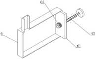
图9为本发明清理筒的剖视图。Fig. 9 is a cross-sectional view of the cleaning cartridge of the present invention.
图中:1、采样管;11、导向管;12、集中管;2、转盘;21、轴柱;22、连接环;3、连管;31、分管;32、采样筒;33、转环;331、限位板;34、弹簧管;341、软管;342、支撑弹簧;35、转板;4、扇筒;41、加压管;42、限位筒;421、连接槽;422、限位槽;423、挡板;5、连接板;6、清理筒;61、加压板;62、加压杆;63、拉力弹簧;7、回流管;71、阀门;8、监测探头。In the figure: 1. Sampling pipe; 11. Guide pipe; 12. Concentrating pipe; 2. Turntable; 21. Shaft column; 22. Connecting ring; 3. Connecting pipe; ; 331, limit plate; 34, spring tube; 341, flexible pipe; 342, support spring; , limit groove; 423, baffle plate; 5, connecting plate; 6, cleaning cylinder; 61, pressure plate; 62, pressure rod; 63, tension spring; 7, return pipe; 71, valve; 8, monitoring probe .
具体实施方式detailed description
实施例1Example 1
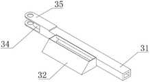
如图1所示,一种油烟连续采样装置,包括采样管1,所述采样管1内端与采样轮连接,采样管1外端与监测探头8连接,采样轮包括与采样管1固定连接且连通的轮盘,轮盘侧面与连管3转动连接且连通,连管3上连接有线性阵列的采样筒32,采样筒32与连管3连通,所述采样管1与监测探头8连接处连接回流管7。As shown in Figure 1, a continuous oil fume sampling device includes a
在安装时,将采样管1送入至排烟通道内,使采集轮靠近排烟通道中心位置,通过连接板5将采样管1固定于排烟管道内部,采集轮采用固定于采样管1中部的侧面带有通孔的圆筒,套筒套于该圆筒外侧并与该圆筒同轴转动连接,套筒外部连接环22形阵列的连管3并且连管3与套筒内部连通,连管3上连接采样筒32,在排烟中,气流吹过采样筒32,对采样筒32产生横向的驱动作用,使连管3转动,气流通过采样筒32时,在气体压力作用下,气流进入到采样管1中,依次经过连管3、套筒、圆筒进入到采样管1中,气流流经采样管1连接检测探头处被监测,连管3连接的采样筒32转动中不断变换位置实现多点采样,采集数据更加准确,并且监测探头8并非位于排烟通道内部,相较于位于排烟管道内部环境,采样管1中环境改善明显,因此能够延长监测探头8的使用寿命,经监测探头8测后的油烟气流经过回流管7重新进入到油烟管道中。When installing, send the
实施例2Example 2
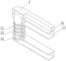
如图1-5所示,一种油烟连续采样装置,包括采样管1,所述采样管1内端与采样轮连接,采样管1外端与监测探头8连接,采样轮包括与采样管1固定连接且连通的轮盘,轮盘侧面与连管3转动连接且连通,连管3上连接有线性阵列的采样筒32,采样筒32与连管3连通,所述采样管1与监测探头8连接处连接回流管7,所述采样筒32为棱台状,采样筒32侧面与水平面倾斜,采样筒32中部与采样管1连通,所述连管3包括多段依次转动连接的分管31,相邻分管31之间通过弹簧管34连接,每个分管31中部对应连接采样筒32,所述弹簧管34包括连接于两个相邻分管31支架的软管341,软管341内部连接支撑弹簧342,支撑弹簧342两端连接两个相邻分管31之间,相邻分管31外侧通过销轴转动连接。As shown in Figures 1-5, a continuous oil fume sampling device includes a
在实施例1的基础上,为使采样筒32能够在气流驱动下受到水平方向的驱动力,将采样筒32设置为侧面倾斜的结构,气流由下向上冲击采样筒32倾斜一侧时对采样筒32的冲击力一部分转换为水平方向的驱动力,从而使采样筒32转动,并且采样筒32设置为底部开口大于截面大于顶部开口截面的结构,使气流流经采样筒32时气体被压缩,从而能够使部分气流在一定压力下被压入到采样管1中,实现定量采集。On the basis of
在实施例1的基础上,为使连管3长度适应一定范围内不同内径的排烟管道,将连管3设置为多个分管31依次通过弹簧管34连接的方式,在连管3两倍长度与采样轮直径之和小于排烟通道内径时,连管3处于自然伸长状态,分管31之间的支撑弹簧342处于自然伸长状态,软管341轴线近似于直线,在排烟管道内径较小时,通过施加外力的方式使相邻两个分管31连接的弹簧管34弯曲,减小连管3外端到采样轮之间的直线距离,使连管3能够被容纳于排烟管道内部,以适用于不同直径的排烟管道,在弹簧管34弯曲状态下,软管341轴线为曲线,支撑弹簧342固定于软管341内壁使软管341通道处于张开状态,相邻分管31之间通过转板35转动连接,使相邻分管31保持竖直方向相对固定。On the basis of
实施例3Example 3
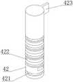
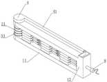
如图1-8所示,一种油烟连续采样装置,包括采样管1,所述采样管1内端与采样轮连接,采样管1外端与监测探头8连接,采样轮包括与采样管1固定连接且连通的轮盘,轮盘侧面与连管3转动连接且连通,连管3上连接有线性阵列的采样筒32,采样筒32与连管3连通,所述采样管1与监测探头8连接处连接回流管7,所述轮盘包括多个同轴转动连接的转环33,每个转环33侧面对应连接一个连管3,连管3与转环33内部连通,所述采样管1包括两个平行的导向管11,两个导向管11之间固定连接轴柱21,轴柱21侧面设置有环槽,所述转环33位于环槽内,两个所述导向管11截面为矩形,两个导向管11外端与集中管12连通,集中管12外端与连接板5滑动连接,连接板5上连接贯穿的连接螺钉,连接板5与集中管12螺纹连接,两个所述导向管11之间转动连接有位于轴柱21内且与轴柱21同轴转动连接的限位筒42,限位筒42侧面设置有由下到上扇角渐增的限位槽422,转环33内固定连接插接于限位槽422内的限位板331,限位筒42顶部贯穿上方的导向管11位于扇筒4内,限位筒42固定连接挡板423,扇筒4与加压管41连通。As shown in Figure 1-8, a continuous oil fume sampling device includes a sampling tube 1, the inner end of the sampling tube 1 is connected to the sampling wheel, the outer end of the sampling tube 1 is connected to the monitoring probe 8, and the sampling wheel includes a sampling tube 1 Fixedly connected and communicated roulette, the side of the roulette is rotatably connected and communicated with the connecting pipe 3, the connecting pipe 3 is connected with a linear array of sampling cylinders 32, the sampling cylinder 32 is connected with the connecting pipe 3, and the sampling pipe 1 is connected with the monitoring probe 8, the connection point is connected to the return pipe 7, and the wheel disc includes a plurality of swivels 33 connected by coaxial rotation, and each swivel 33 side is connected to a connecting pipe 3 correspondingly, and the connecting pipe 3 communicates with the swivel 33 internally, and the sampling The tube 1 includes two parallel guide tubes 11, the two guide tubes 11 are fixedly connected to the shaft column 21, the side of the shaft column 21 is provided with a ring groove, the swivel 33 is located in the ring groove, and the two guide tubes 11 The cross-section is rectangular, the outer ends of the two guide pipes 11 communicate with the centralizing pipe 12, the outer ends of the centralizing pipe 12 are slidingly connected with the connecting plate 5, the connecting plate 5 is connected with connecting screws that pass through, and the connecting plate 5 is threadedly connected with the centralizing pipe 12. Between the two
实施例1中圆筒外部连接套筒的方式导致多个环形阵列的连管3处于同一水平高度,并且连管3与套筒固定,因此连管3外端形成的圆直径固定,在安装中需要在排烟通道侧面开较大的孔以将采集管、连管3放入,本实施例中,将连管3设置为与采样管1转动连接的方式,具体如下,将采样管1设置为两个平行的导向管11连接的方式,导向管11左端固定连接轴柱21,轴柱21内侧与连接环22固定连接,连接环22嵌于限位筒42侧面的连接槽421内并且连接环22于连接槽421内转动,轴柱21外侧设置与转环33连接的由下到上均匀分布的多个环槽,环槽内连接转环33,转环33内部与连管3连通,在未安装状态下,可通过转动连管3的方式,多个连管3均处于两个导向管11之间,如图8所示,在安装中,仅需在排烟管道侧面开设与采样管1截面大小相同的开口即可将采样管1插入到排烟管道内部,安装更加方便,并能够在安装后通过连接板5封闭排烟管道侧面开口。The method of connecting the outside of the cylinder to the sleeve in Example 1 results in multiple annular arrays of connecting
采样管1插入到排烟管道之后,为使多个连管3呈环形阵列分布,由加压管41外端开口一侧加压,在加压状态下能够使扇筒4内部的挡板423一侧受到压力,进而使挡板423所连接的限位筒42转动,需要注意的是,为使挡板423一侧受压并且使挡板423转动至一定位置后停止转动,需要在扇筒4内部设置限位,并且在限位处一侧设置开口,以使挡板423受力另一侧的气压保持恒定,在限位筒42转动时,限位筒42侧面的限位槽422方位改变,如图7所示,位于最底部的限位槽422两侧与限位板331两侧贴合,因此该限位板331所连接的转环33以及连管3随限位筒42转动而转动;位于上一个限位槽422扇面相对较大,在限位筒42转动至限位槽422另一侧与限位板331接触时,该限位板331所连接的转环33以及连管3转动,因此能够使两个连管3之间具有一定的夹角,依次类推,使限位筒42持续转动可使多个连管3呈环形阵列分布,由于此时限位板331仅于限位槽422的一侧贴合,在排气时连管3受到的驱动力应当使该连管3所连接的转环33向限位板331贴合于对应限位槽422的一侧,故而应当注意采集筒倾斜一侧的设置方向,拆卸时,对挡板423反向加压使挡板423反向转动即可使连管3位于同一竖平面上,控制限位筒42转动至与采样管1平齐即可抽出采样管1。After the
实施例4Example 4
如图1-9所示,一种油烟连续采样装置,包括采样管1,所述采样管1内端与采样轮连接,采样管1外端与监测探头8连接,采样轮包括与采样管1固定连接且连通的轮盘,轮盘侧面与连管3转动连接且连通,连管3上连接有线性阵列的采样筒32,采样筒32与连管3连通,所述采样管1与监测探头8连接处连接回流管7,所述采样管1与回流管7连接处连接清理筒6,清理筒6侧面连接加压筒,加压筒内螺纹连接加压杆62,加压杆62与清理筒6内的加压板61通过拉力弹簧63连接所述加压杆62与连接环22转动连接,拉力弹簧63连接于转环33与加压板61之间。As shown in Figure 1-9, a continuous oil fume sampling device includes a
在集中管12底部连接清理筒6,采集管工作一段时间后,为清理采集管内部粘附物,关闭回流管7上的阀门71,转动加压杆62使加压杆62向清理筒6内部移动,使加压杆62轴向固定连接、径向转动连接的连接环22拉动拉力弹簧63伸长,在弹簧拉力作用下压力板移动使清理液被压入到采样管1中,进而对采样管1进行清洁,清洁水由采样筒32排出,拉力弹簧63加压供水的方式,使水流更快,冲刷采样管1速率更快。The cleaning
Claims (10)
Priority Applications (1)
| Application Number | Priority Date | Filing Date | Title |
|---|---|---|---|
| CN202211223899.4ACN115524178A (en) | 2022-10-08 | 2022-10-08 | Continuous sampling device of oil smoke |
Applications Claiming Priority (1)
| Application Number | Priority Date | Filing Date | Title |
|---|---|---|---|
| CN202211223899.4ACN115524178A (en) | 2022-10-08 | 2022-10-08 | Continuous sampling device of oil smoke |
Publications (1)
| Publication Number | Publication Date |
|---|---|
| CN115524178Atrue CN115524178A (en) | 2022-12-27 |
Family
ID=84701839
Family Applications (1)
| Application Number | Title | Priority Date | Filing Date |
|---|---|---|---|
| CN202211223899.4APendingCN115524178A (en) | 2022-10-08 | 2022-10-08 | Continuous sampling device of oil smoke |
Country Status (1)
| Country | Link |
|---|---|
| CN (1) | CN115524178A (en) |
Cited By (1)
| Publication number | Priority date | Publication date | Assignee | Title |
|---|---|---|---|---|
| CN116223134A (en)* | 2023-03-09 | 2023-06-06 | 江苏海伊特环保科技有限公司 | Real-time detection device for working waste gas of incinerator |
Citations (4)
| Publication number | Priority date | Publication date | Assignee | Title |
|---|---|---|---|---|
| CN109946766A (en)* | 2019-04-01 | 2019-06-28 | 王久钰 | Method and device for monitoring construction process |
| CN211825554U (en)* | 2019-12-31 | 2020-10-30 | 江苏蓝创智能科技股份有限公司 | A balanced sampling system of oil smoke detection for clarifier pipe front end of discharging fume |
| CN114236044A (en)* | 2021-11-29 | 2022-03-25 | 合肥清风环保科技有限公司 | Oil smoke online detection device capable of collecting samples in multiple directions and use method thereof |
| CN115078205A (en)* | 2022-07-27 | 2022-09-20 | 杭州老板电器股份有限公司 | Oil smoke online monitoring device and oil smoke online monitoring method |
- 2022
- 2022-10-08CNCN202211223899.4Apatent/CN115524178A/enactivePending
Patent Citations (4)
| Publication number | Priority date | Publication date | Assignee | Title |
|---|---|---|---|---|
| CN109946766A (en)* | 2019-04-01 | 2019-06-28 | 王久钰 | Method and device for monitoring construction process |
| CN211825554U (en)* | 2019-12-31 | 2020-10-30 | 江苏蓝创智能科技股份有限公司 | A balanced sampling system of oil smoke detection for clarifier pipe front end of discharging fume |
| CN114236044A (en)* | 2021-11-29 | 2022-03-25 | 合肥清风环保科技有限公司 | Oil smoke online detection device capable of collecting samples in multiple directions and use method thereof |
| CN115078205A (en)* | 2022-07-27 | 2022-09-20 | 杭州老板电器股份有限公司 | Oil smoke online monitoring device and oil smoke online monitoring method |
Cited By (2)
| Publication number | Priority date | Publication date | Assignee | Title |
|---|---|---|---|---|
| CN116223134A (en)* | 2023-03-09 | 2023-06-06 | 江苏海伊特环保科技有限公司 | Real-time detection device for working waste gas of incinerator |
| CN116223134B (en)* | 2023-03-09 | 2025-09-19 | 江苏海伊特环保科技有限公司 | Real-time detection device for working waste gas of incinerator |
Similar Documents
| Publication | Publication Date | Title |
|---|---|---|
| CN115524178A (en) | Continuous sampling device of oil smoke | |
| CN100374842C (en) | A Measuring Device for Flat Wall Fluid Frictional Resistance Based on Open Cycle | |
| CN116878976A (en) | Petrochemical torch waste gas emission sampling device | |
| CN109629381A (en) | A kind of pavement flatness checking device | |
| CN114414313A (en) | A kind of river water quality environmental protection testing sampling equipment | |
| CN206095718U (en) | Sampling device suitable for low concentration particulate matter | |
| CN104316359B (en) | A kind of multilamellar water sampler | |
| CN219244712U (en) | A pipeline sewage flowmeter | |
| CN220005284U (en) | Pipeline cleaning equipment | |
| CN118088946A (en) | Acoustic emission-based valve internal leakage detection device | |
| CN216594319U (en) | A portable multifunctional groundwater sampler | |
| CN206725842U (en) | A kind of industrial pipeline endoscope adaptive supporting frame | |
| CN110346183A (en) | A kind of artificial swamp matrix sampling detecting device and permeability test method | |
| CN215726572U (en) | Building outer wall infiltration testing arrangement for engineering supervision | |
| CN208270305U (en) | A kind of Suction filtration device | |
| CN114324130A (en) | Corrosion-resistant check out test set of sewer line | |
| CN220670437U (en) | Portable pressure pipeline detection device | |
| CN110849420A (en) | An experimental device for studying liquid carrying in undulating pipelines | |
| CN221594687U (en) | Oil smoke particulate matter concentration check out test set | |
| CN114414007A (en) | Revolver self-conversion multi-caliber rectangular flow verification device | |
| CN221350750U (en) | Water quality sampler | |
| CN207991815U (en) | A collection device for pump characteristic test | |
| CN219641007U (en) | Sewage flow intelligent detection equipment | |
| CN221745434U (en) | A fire protection pipeline air tightness detection device | |
| CN222280252U (en) | Lining pipe sampling rod structure of flue gas sampler |
Legal Events
| Date | Code | Title | Description |
|---|---|---|---|
| PB01 | Publication | ||
| PB01 | Publication | ||
| SE01 | Entry into force of request for substantive examination | ||
| SE01 | Entry into force of request for substantive examination |