CN115517818A - Ring shrink device - Google Patents
Ring shrink deviceDownload PDFInfo
- Publication number
- CN115517818A CN115517818ACN202111659834.XACN202111659834ACN115517818ACN 115517818 ACN115517818 ACN 115517818ACN 202111659834 ACN202111659834 ACN 202111659834ACN 115517818 ACN115517818 ACN 115517818A
- Authority
- CN
- China
- Prior art keywords
- proximal
- distal
- ring
- traction
- sleeve
- Prior art date
- Legal status (The legal status is an assumption and is not a legal conclusion. Google has not performed a legal analysis and makes no representation as to the accuracy of the status listed.)
- Pending
Links
Images


Classifications
- A—HUMAN NECESSITIES
- A61—MEDICAL OR VETERINARY SCIENCE; HYGIENE
- A61F—FILTERS IMPLANTABLE INTO BLOOD VESSELS; PROSTHESES; DEVICES PROVIDING PATENCY TO, OR PREVENTING COLLAPSING OF, TUBULAR STRUCTURES OF THE BODY, e.g. STENTS; ORTHOPAEDIC, NURSING OR CONTRACEPTIVE DEVICES; FOMENTATION; TREATMENT OR PROTECTION OF EYES OR EARS; BANDAGES, DRESSINGS OR ABSORBENT PADS; FIRST-AID KITS
- A61F2/00—Filters implantable into blood vessels; Prostheses, i.e. artificial substitutes or replacements for parts of the body; Appliances for connecting them with the body; Devices providing patency to, or preventing collapsing of, tubular structures of the body, e.g. stents
- A61F2/02—Prostheses implantable into the body
- A61F2/24—Heart valves ; Vascular valves, e.g. venous valves; Heart implants, e.g. passive devices for improving the function of the native valve or the heart muscle; Transmyocardial revascularisation [TMR] devices; Valves implantable in the body
- A61F2/2442—Annuloplasty rings or inserts for correcting the valve shape; Implants for improving the function of a native heart valve
- A61F2/246—Devices for obstructing a leak through a native valve in a closed condition
- A—HUMAN NECESSITIES
- A61—MEDICAL OR VETERINARY SCIENCE; HYGIENE
- A61F—FILTERS IMPLANTABLE INTO BLOOD VESSELS; PROSTHESES; DEVICES PROVIDING PATENCY TO, OR PREVENTING COLLAPSING OF, TUBULAR STRUCTURES OF THE BODY, e.g. STENTS; ORTHOPAEDIC, NURSING OR CONTRACEPTIVE DEVICES; FOMENTATION; TREATMENT OR PROTECTION OF EYES OR EARS; BANDAGES, DRESSINGS OR ABSORBENT PADS; FIRST-AID KITS
- A61F2/00—Filters implantable into blood vessels; Prostheses, i.e. artificial substitutes or replacements for parts of the body; Appliances for connecting them with the body; Devices providing patency to, or preventing collapsing of, tubular structures of the body, e.g. stents
- A61F2/02—Prostheses implantable into the body
- A61F2/24—Heart valves ; Vascular valves, e.g. venous valves; Heart implants, e.g. passive devices for improving the function of the native valve or the heart muscle; Transmyocardial revascularisation [TMR] devices; Valves implantable in the body
- A61F2/2442—Annuloplasty rings or inserts for correcting the valve shape; Implants for improving the function of a native heart valve
- A61F2/2466—Delivery devices therefor
Landscapes
- Health & Medical Sciences (AREA)
- Cardiology (AREA)
- Oral & Maxillofacial Surgery (AREA)
- Transplantation (AREA)
- Engineering & Computer Science (AREA)
- Biomedical Technology (AREA)
- Heart & Thoracic Surgery (AREA)
- Vascular Medicine (AREA)
- Life Sciences & Earth Sciences (AREA)
- Animal Behavior & Ethology (AREA)
- General Health & Medical Sciences (AREA)
- Public Health (AREA)
- Veterinary Medicine (AREA)
- Media Introduction/Drainage Providing Device (AREA)
Abstract
Translated fromChinese
Description
Translated fromChinese技术领域technical field
本申请属于医疗器械技术领域,更具体地说,是涉及一种环缩装置。The application belongs to the technical field of medical devices, and more specifically relates to a ring constriction device.
背景技术Background technique
二尖瓣是心脏的一部分,位于左心房和左心室之间。血液由左心房泵入左心室,当左心室收缩将血液泵入全身时,二尖瓣关闭以防止血液被泵回左心房。在一些患者中,由于遗传畸形、疾病或损伤等原因,导致二尖瓣不能正常关闭,俗称为反流,即心肌每次收缩时血液都会被泵入心房。反流会降低循环效率,必须加以纠正。The mitral valve is a part of the heart located between the left atrium and left ventricle. Blood is pumped from the left atrium into the left ventricle, and when the left ventricle contracts to pump blood throughout the body, the mitral valve closes to prevent blood from being pumped back into the left atrium. In some patients, due to genetic abnormalities, disease or injury, the mitral valve does not close properly, commonly known as regurgitation, in which blood is pumped into the atria each time the heart muscle contracts. Backflow reduces cycle efficiency and must be corrected.
现在通过微创介入手术治疗,是大部分心脏瓣膜疾病的更优选择,主要的介入治疗方式有人工腱索植入术、二尖瓣瓣环成形术及二尖瓣缘对缘修复术等。其中瓣环成形术有直接瓣环成形术和间接瓣环成形术两种。间接瓣环成形术主要是利用收紧二尖瓣环周围的血管组织来达到收缩二尖瓣环,使二尖瓣叶关闭紧实的目的。冠状窦-心大静脉主要是围绕在二尖瓣环周边的血管,这也使它成为了间接瓣环成形术的最佳植入对象。At present, minimally invasive interventional surgery is the better choice for most heart valve diseases. The main interventional treatment methods include artificial chordal implantation, mitral annuloplasty, and mitral valve edge-to-edge repair. There are two types of annuloplasty: direct annuloplasty and indirect annuloplasty. Indirect annuloplasty mainly uses the vascular tissue around the mitral valve ring to shrink the mitral valve ring and make the mitral valve leaflets close tightly. The coronary sinus-great cardiac vein is primarily a vessel surrounding the mitral annulus, making it an optimal candidate for indirect annuloplasty.
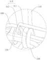
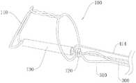
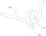
参照图1至图5,该装置有两个锚定件,分别是:远端锚10和近端锚20。远端锚10和近端锚20通过连接杆30连接在一起。远端锚10包括远端锚本体11及远端套管13,远端锚本体11在连接杆30上缠绕以形成远端限位环12,连接杆30在远端限位环12远离远端套管13的一侧形成有远端限位部31;近端锚20包括近端锚本体21及近端套管23,近端锚本体21在连接杆30上缠绕以形成近端限位环22,连接杆30在近端限位环22远离近端套管23的一侧形成有近端限位部32。Referring to FIGS. 1 to 5 , the device has two anchors, namely: a
该装置通过输送导管40从颈静脉进入体内,在冠状窦-心大静脉血管1中植入,远端锚本体11从输送导管40中释放出来后,利用输送导管40将远端限位环12推入远端限位部31与远端套管13之间,远端锚本体11膨胀冠状窦-心大静脉血管1,锚定在冠状窦-心大静脉血管1内;然后带动输送导管40从血管内向外撤出,以带动远端锚10向血管外的方向移动,从而使二尖瓣环2肌肉组织缩紧,进而间接缩小二尖瓣环2直径,此时输送导管40后撤释放近端锚本体21,近端锚20释放后通过推杆50将近端限位环22推入近端套管23与近端限位部32之间,近端锚本体21膨胀撑大冠状窦-心大静脉血管1,锚定在冠状窦-心大静脉血管1内,装置释放完毕后二尖瓣环2直径缩小,从而使二尖瓣叶关闭密实,改善二尖瓣返流。The device enters the body from the jugular vein through the
但是,现有装置中的远端锚10和近端锚20在锁定状态下只能通过输送导管40强制回收,而处于锁定状态下的远端锚10和近端锚20属于一种稳固的状态,要将膨胀后的远端锚10和近端锚20收入到直径较小的输送导管40内,回收内阻力很大,且输送导管40需要很强的刚性支撑,如输送导管40刚性不够,则容易出现输送导管40弯折,极易导致装置回收失败。However, the
发明内容Contents of the invention
本申请实施例的目的在于提供一种环缩装置,旨在解决现有技术中二尖瓣装置释放后不易回收的技术问题。The purpose of the embodiments of the present application is to provide a ring constriction device, aiming at solving the technical problem in the prior art that the mitral valve device is not easy to recover after being released.
为实现上述目的,根据本申请的一个方面,提供了一种环缩装置,包括锚定部及解锁部,锚定部具有膨胀以锚固在血管内的锚定位置,及能够回收至输送导管内的回收位置;解锁部与锚定部连接,解锁部能够带动锚定部从锚定位置切换至回收位置。In order to achieve the above object, according to one aspect of the present application, a constriction device is provided, including an anchoring part and an unlocking part, the anchoring part has an anchoring position expanded to be anchored in the blood vessel, and can be recovered into the delivery catheter recovery position; the unlocking part is connected with the anchoring part, and the unlocking part can drive the anchoring part to switch from the anchoring position to the recovery position.
可选地,锚定部包括远端锚和近端锚,近端锚位于远端锚的第一侧;远端锚包括远端锚本体,远端锚本体具有能够膨胀以锚固在血管内的第一膨胀位置,及能够变形收缩的第一收缩位置;解锁部能够带动远端锚本体从第一膨胀位置切换至第一收缩位置;近端锚包括近端锚本体,近端锚本体具有能够膨胀以锚固在血管内的第二膨胀位置,及能够变形收缩的第二收缩位置;解锁部能够带动近端锚本体从第二膨胀位置切换至第二收缩位置;当远端锚本体处于第一膨胀位置,且近端锚本体处于第二膨胀位置时,锚定部处于锚定位置;当远端锚本体处于第一收缩位置,且近端锚本体处于第二收缩位置时,锚定部处于回收位置。Optionally, the anchoring portion includes a distal anchor and a proximal anchor, the proximal anchor is located on a first side of the distal anchor; the distal anchor includes a distal anchor body, and the distal anchor body has a diameter capable of being expanded to be anchored in a blood vessel. The first expansion position, and the first contraction position capable of deformation and contraction; the unlocking part can drive the distal anchor body to switch from the first expansion position to the first contraction position; the proximal anchor includes a proximal anchor body, and the proximal anchor body has a expand to be anchored in the second expansion position in the blood vessel, and the second contraction position capable of deformation and contraction; the unlocking part can drive the proximal anchor body to switch from the second expansion position to the second contraction position; when the distal anchor body is in the first In the expanded position, and the proximal anchor body is in the second expanded position, the anchoring part is in the anchoring position; when the distal anchor body is in the first retracted position, and the proximal anchor body is in the second contracted position, the anchoring part is in the Recycle location.
可选地,锚定部还包括连接件,连接件设置于远端锚和近端锚之间,且分别与远端锚和近端锚连接;远端锚本体在连接件上缠绕形成有远端限位环,连接件在远端限位环靠近近端锚的一侧形成有远端限位部,远端限位环被限位在远端限位部远离近端锚的一侧,此时远端锚本体处于第一膨胀位置;远端限位环可滑动的安装于连接件,解锁部能够带动远端限位环沿连接件的长度方向经过远端限位部,以使远端锚本体从第一膨胀位置切换至第一收缩位置;近端锚本体在连接件上缠绕形成有近端限位环,连接件在近端限位环远离远端锚的一侧形成有近端限位部,近端限位环被限位在近端限位部靠近远端锚的一侧,此时近端锚本体处于第二膨胀位置;近端限位环可滑动的安装于连接件,解锁部能够带动近端限位环沿连接件的长度方向经过近端限位部,以使近端锚本体从第二膨胀位置切换至第二收缩位置。Optionally, the anchoring part also includes a connecting piece, which is arranged between the distal anchor and the proximal anchor, and is respectively connected to the distal anchor and the proximal anchor; the distal anchor body is wound on the connecting piece to form a distal The end limit ring, the connector forms a distal limit portion on the side of the distal limit ring close to the proximal anchor, and the distal limit ring is limited on the side of the distal limit portion away from the proximal anchor, At this time, the distal anchor body is in the first expanded position; the distal limiting ring is slidably installed on the connector, and the unlocking part can drive the distal limiting ring to pass through the distal limiting part along the length direction of the connector, so that the distal The end anchor body is switched from the first expanded position to the first retracted position; the proximal anchor body is wound on the connector to form a proximal stop ring, and the connector forms a proximal stop ring on the side of the proximal stop ring away from the distal anchor. end limiter, the proximal limiter is limited on the side of the proximal limiter close to the distal anchor, and the proximal anchor body is in the second expanded position; the proximal limiter is slidably mounted on the connection The unlocking part can drive the proximal limiting ring to pass the proximal limiting part along the length direction of the connecting part, so that the proximal anchor body can switch from the second expansion position to the second contraction position.
可选地,解锁部包括远端牵引部、近端牵引部及导向件;远端牵引部位于远端限位环远离远端限位部的一侧,导向件穿设于远端限位环及远端牵引部,远端牵引部能够沿导向件的延伸方向移动,远端牵引部能够牵引远端限位环沿连接件的长度方向经过远端限位部;近端牵引部位于近端限位环远离近端限位部的一侧,导向件穿设于近端限位环及近端牵引部,近端牵引部能够沿导向件的延伸方向移动,近端牵引部能够牵引近端限位环沿连接件的长度方向经过近端限位部。Optionally, the unlocking part includes a distal traction part, a proximal traction part and a guide; the distal traction part is located on the side of the distal limiting ring away from the distal limiting part, and the guide is passed through the distal limiting ring and the distal traction part, the distal traction part can move along the extension direction of the guide piece, the distal traction part can pull the distal limit ring through the distal limit part along the length direction of the connector; the proximal traction part is located at the proximal end The limit ring is away from the side of the proximal limit part, and the guide part is passed through the proximal limit ring and the proximal traction part. The proximal traction part can move along the extension direction of the guide part, and the proximal traction part can pull the proximal The limiting ring passes through the proximal limiting part along the length direction of the connecting piece.
可选地,远端牵引部为远端牵引件,远端牵引件上形成有远端牵引环,远端牵引环位于远端限位环远离远端限位部的一侧,导向件穿过远端牵引环;或,远端牵引部为单根绳,单根绳对折形成两股远端拉绳,两股远端拉绳的交界处位于远端限位环远离远端限位部的一侧,且搭设在导向件上,以牵引远端限位环沿连接件的长度方向经过远端限位部。Optionally, the distal traction part is a distal traction member, and a distal traction ring is formed on the distal traction member. The distal traction ring is located on the side of the distal limit ring away from the distal limit part, and the guide passes through The distal traction ring; or, the distal traction part is a single rope, and the single rope is folded in half to form two distal pull ropes. One side, and set on the guide piece, so as to pull the distal limiting ring through the distal limiting part along the length direction of the connecting piece.
可选地,近端牵引部为近端牵引件,近端牵引件上形成有近端牵引环,近端牵引环位于近端限位环远离近端限位部的一侧,导向件穿过近端牵引环;或,近端牵引部为单根绳,单根绳对折形成两股近端拉绳,两股近端拉绳的交界点位于近端限位环远离近端限位部的一侧,且搭设在导向件上,以牵引近端限位环沿连接件的长度方向穿过近端限位部。Optionally, the proximal traction part is a proximal traction part, and a proximal traction ring is formed on the proximal traction part. The proximal traction ring is located on the side of the proximal limit ring away from the proximal limit part, and the guide passes through the The proximal traction ring; or, the proximal traction part is a single rope, and the single rope is folded in half to form two near-end pull ropes. One side, and set on the guide piece, so as to pull the proximal limiting ring through the proximal limiting part along the length direction of the connecting piece.
可选地,解锁部包括远端牵引绳和近端牵引绳,其中,远端牵引绳的第一端从远端限位环远离远端限位部的一侧穿过远端限位环,并向远端限位部远离远端限位环的方向延伸,远端牵引绳的第二端向远端限位部远离远端限位环的方向延伸;近端牵引绳的第一端从近端限位环远离近端限位部的一侧穿过近端限位环,并向近端限位部远离近端限位环的方向延伸;近端牵引绳的第二端向近端限位部远离近端限位环的方向延伸。Optionally, the unlocking part includes a distal pulling rope and a proximal pulling rope, wherein the first end of the distal pulling rope passes through the distal limiting ring from a side of the distal limiting ring away from the distal limiting part, And extend to the far-end limiting part away from the direction of the far-end limiting ring, the second end of the far-end traction rope extends to the far-end limiting part away from the direction of the far-end limiting ring; the first end of the proximal pulling rope extends from the The side of the proximal limiting ring away from the proximal limiting part passes through the proximal limiting ring, and extends toward the direction that the proximal limiting part is away from the proximal limiting ring; the second end of the proximal pulling rope moves toward the proximal The limiting portion extends away from the proximal limiting ring.
可选地,远端锚还包括远端套管,远端套管远离近端锚的一端为第一端,远端锚本体的两端能够从远端套管的第一端穿进远端套管内,且与远端套管连接;近端锚还包括近端套管,近端套管靠近远端锚的一端为第一端,近端锚本体的两端能够穿进近端套管内,且与近端套管连接。Optionally, the distal anchor further includes a distal sleeve, the end of the distal sleeve away from the proximal anchor is the first end, and the two ends of the distal anchor body can pass through the first end of the distal sleeve into the distal end. The proximal anchor also includes a proximal sleeve, the end of the proximal sleeve close to the distal anchor is the first end, and the two ends of the proximal anchor body can pass into the proximal sleeve , and connected to the proximal sleeve.
可选地,远端套管第二端的外周面上开设有远端豁口,导向件的第一端通过远端豁口穿进远端套管内。Optionally, a distal notch is formed on the outer peripheral surface of the second end of the distal sleeve, and the first end of the guide member penetrates into the distal sleeve through the distal notch.
可选地,远端套管的外周面开设有让位部,让位部的第一端与远端豁口连通,让位部的第二端延伸至远端套管第二端的端面,导向件放置于让位部内,并通过远端豁口穿进远端套管内。Optionally, a relief portion is provided on the outer peripheral surface of the distal sleeve, the first end of the relief portion communicates with the distal notch, the second end of the relief portion extends to the end surface of the second end of the distal sleeve, and the guide member Placed in the abdication, and passed through the distal notch into the distal cannula.
可选地,远端套管上设置有固定件,导向件与固定件螺纹连接。Optionally, a fixing piece is provided on the distal sleeve, and the guide piece is screwed into the fixing piece.
可选地,远端限位环包括远端限位环本体及远端附属环,远端附属环设置于远端限位环本体的一侧,且与远端附属环连接,导向件穿过远端附属环。Optionally, the distal limiting ring includes a distal limiting ring body and a distal accessory ring, the distal accessory ring is arranged on one side of the distal limiting ring body, and is connected with the distal accessory ring, and the guide member passes through Distal accessory ring.
可选地,近端限位环上形成有第一穿设孔和第二穿设孔,连接件穿过第一穿设孔和第二穿设孔,并穿进近端套管内,导向件穿过第二穿设孔并位于近端套管外侧。Optionally, a first perforation hole and a second perforation hole are formed on the proximal limit ring, the connecting piece passes through the first perforation hole and the second perforation hole, and penetrates into the proximal sleeve, and the guide piece Through the second piercing hole and outside the proximal sleeve.
可选地,连接件为两根连接杆,两根连接杆中的一根连接杆形成有缠绕限位部,导向件穿过缠绕限位部。Optionally, the connecting member is two connecting rods, one of the two connecting rods is formed with a winding limiting portion, and the guide member passes through the winding limiting portion.
可选地,近端套管第一端的外周面开设有近端豁口,导向件从近端豁口穿进近端套管内,并从近端套管的第一端向远端套管的方向穿出;近端锚本体的两端从近端豁口穿进近端套管内,且与近端套管连接;和/或,近端锚还包括限位管,限位管设置于近端套管的外周,导向件穿过限位管。Optionally, a proximal notch is provided on the outer peripheral surface of the first end of the proximal sleeve, and the guide member penetrates into the proximal sleeve from the proximal notch, and moves from the first end of the proximal sleeve to the direction of the distal sleeve. The two ends of the proximal anchor body pass through the proximal sleeve through the proximal gap and are connected to the proximal sleeve; and/or, the proximal anchor also includes a limiting tube, which is arranged on the proximal sleeve The outer circumference of the tube, the guide piece passes through the limiting tube.
可选地,连接件为两根连接杆,两根连接杆中的一根连接杆形成有缠绕限位部,导向件穿过缠绕限位部。Optionally, the connecting member is two connecting rods, one of the two connecting rods is formed with a winding limiting portion, and the guide member passes through the winding limiting portion.
可选地,近端限位环包括近端限位环本体及近端附属环,近端附属环设置于近端限位环本体的一侧,且与近端限位环本体连接,近端附属环形成第二穿设孔,导向件穿过近端附属环。Optionally, the proximal limiting ring includes a proximal limiting ring body and a proximal accessory ring. The proximal accessory ring is arranged on one side of the proximal limiting ring body and is connected to the proximal limiting ring body. The accessory ring forms a second piercing hole, and the guide piece passes through the proximal accessory ring.
本申请提供的环缩装置的有益效果在于:与现有技术相比,在本申请中,当锚定部需回收和重新定位时,拉动解锁部向外撤出,使锚定部从锚定位置切换至回收位置,此时锚定部的大小与输送导管的内径相近,大大降低了锚定部回收至输送导管内的回收阻力。本申请中的解锁部不仅提高了锚定部的回收成功率,同时也缩短了手术成本及缩短了手术时间。The beneficial effect of the ring constriction device provided by the present application is that compared with the prior art, in the present application, when the anchoring part needs to be recovered and repositioned, the unlocking part is pulled outwards, so that the anchoring part can be released from the anchoring part. The position is switched to the recovery position. At this time, the size of the anchoring part is similar to the inner diameter of the delivery catheter, which greatly reduces the recovery resistance of the anchoring part when it is recovered into the delivery catheter. The unlocking part in the present application not only improves the recovery success rate of the anchoring part, but also reduces operation cost and operation time.
附图说明Description of drawings
为了更清楚地说明本申请实施例中的技术方案,下面将对实施例或现有技术描述中所需要使用的附图作简单地介绍,显而易见地,下面描述中的附图仅仅是本申请的一些实施例,对于本领域普通技术人员来讲,在不付出创造性劳动性的前提下,还可以根据这些附图获得其他的附图。In order to more clearly illustrate the technical solutions in the embodiments of the present application, the accompanying drawings that need to be used in the descriptions of the embodiments or the prior art will be briefly introduced below. Obviously, the accompanying drawings in the following description are only for the present application For some embodiments, those of ordinary skill in the art can also obtain other drawings based on these drawings without paying creative efforts.
图1为背景技术提供的环缩装置在血管内的结构示意图;Fig. 1 is a schematic diagram of the structure of the ring constriction device provided by the background technology in the blood vessel;
图2为背景技术提供的环缩装置中远端锚的结构示意图;FIG. 2 is a schematic structural view of the distal anchor in the ring constriction device provided by the background technology;
图3为背景技术提供的环缩装置中近端锚的结构示意图;3 is a schematic structural view of the proximal anchor in the ring constriction device provided by the background technology;
图4为背景技术提供的环缩装置在血管内投放的示意图;Fig. 4 is a schematic diagram of the intravascular delivery of the ring constriction device provided by the background technology;
图5为背景技术提供的环缩装置在血管内的示意图;Fig. 5 is a schematic diagram of the ring constriction device provided by the background technology in the blood vessel;
图6为本申请实施例提供的环缩装置的结构示意图;FIG. 6 is a schematic structural view of the ring shrinkage device provided in the embodiment of the present application;
图7为本申请实施例提供的环缩装置中远端锚的结构示意图;Fig. 7 is a schematic structural view of the distal anchor in the constriction device provided by the embodiment of the present application;
图8为图7中A处的放大示意图;Fig. 8 is the enlarged schematic view of place A in Fig. 7;
图9为本申请实施例提供的环缩装置中近端锚与推杆的结构示意图;Fig. 9 is a schematic structural view of the proximal anchor and the push rod in the constriction device provided by the embodiment of the present application;
图10为本申请实施例提供的环缩装置中近端锚的结构示意图;Fig. 10 is a schematic structural view of the proximal anchor in the constriction device provided by the embodiment of the present application;
图11为本申请实施例提供的环缩装置中近端拉绳搭设在导向件上的结构示意图;Fig. 11 is a schematic structural view of the near-end drawstring on the guide member in the constriction device provided by the embodiment of the present application;
图12为本申请实施例提供的环缩装置中远端牵引绳穿过远端限位环的结构示意图;Fig. 12 is a schematic structural view of the distal traction rope passing through the distal stop ring in the constriction device provided by the embodiment of the present application;
图13为本申请实施例提供的环缩装置中远端套管上设有让位部的结构示意图;Fig. 13 is a structural schematic diagram of a relief part provided on the distal sleeve in the constriction device provided by the embodiment of the present application;
图14为本申请实施例提供的环缩装置中远端套管上设有固定件的结构示意图;Fig. 14 is a schematic structural view of a fixing member provided on the distal sleeve in the constriction device provided by the embodiment of the present application;
图15为本申请实施例提供的环缩装置中近端限位环的结构示意图;Fig. 15 is a schematic structural view of the proximal stop ring in the ring constriction device provided by the embodiment of the present application;
图16为本申请实施例提供的环缩装置中近端套管设有近端豁口的结构示意图;Fig. 16 is a schematic structural diagram of a proximal notch provided on the proximal sleeve in the constriction device provided by the embodiment of the present application;
图17为本申请实施例提供的环缩装置中近端套管上设有限位管的结构示意图;Fig. 17 is a structural schematic diagram of a limit tube provided on the proximal sleeve in the constriction device provided by the embodiment of the present application;
图18为本申请实施例提供的环缩装置中近端限位环本体及近端附属环连接的结构示意图。Fig. 18 is a structural schematic diagram of the connection between the proximal stop ring body and the proximal accessory ring in the ring constriction device provided by the embodiment of the present application.
上述附图所涉及的标号明细如下:The details of the labels involved in the above drawings are as follows:
10、远端锚;11、远端锚本体;12、远端限位环;13、远端套管;20、近端锚;21、近端锚本体;22、近端限位环;23、近端套管;30、连接杆;31、远端限位部;32、近端限位部;40、输送导管;50、推杆;1、冠状窦-心大静脉血管;2、二尖瓣环。10. Distal anchor; 11. Distal anchor body; 12. Distal stop ring; 13. Distal sleeve; 20. Proximal anchor; 21. Proximal anchor body; 22. Proximal stop ring; 23 , the proximal cannula; 30, the connecting rod; 31, the distal limiting part; 32, the proximal limiting part; 40, the delivery catheter; 50, the push rod; Cube ring.
100、远端锚;110、远端锚本体;120、远端限位环;130、远端套管;131、远端豁口;140、固定件;200、近端锚;210、近端锚本体;220、近端限位环;221、第一穿设孔;222、第二穿设孔;223、近端限位环本体;224、近端附属环;230、近端套管;231、近端豁口;240、限位管;300、连接件;310、远端限位部;320、近端限位部;330、缠绕限位部;400、解锁部;410、远端牵引部;411、远端牵引件;412、远端牵引环;414、远端牵引绳;420、近端牵引部;421、近端牵引件;422、近端牵引环;423、近端拉绳;430、导向件;500、锁丝;600、推杆;700、输送导管。100, distal anchor; 110, distal anchor body; 120, distal stop ring; 130, distal sleeve; 131, distal notch; 140, fixing piece; 200, proximal anchor; 210, proximal anchor Body; 220, proximal stop ring; 221, first piercing hole; 222, second piercing hole; 223, proximal stop ring body; 224, proximal accessory ring; 230, proximal sleeve; 231 , proximal notch; 240, limiting tube; 300, connector; 310, distal limiting part; 320, proximal limiting part; 330, winding limiting part; 400, unlocking part; 410, distal traction part ; 411, the far-end traction part; 412, the far-end traction ring; 414, the far-end traction rope; 420, the proximal traction part; 421, the proximal traction part; 422, the proximal traction ring; 430, guide piece; 500, locking wire; 600, push rod; 700, delivery catheter.
具体实施方式detailed description
为了使本申请所要解决的技术问题、技术方案及有益效果更加清楚明白,以下结合附图及实施例,对本申请进行进一步详细说明。应当理解,此处所描述的具体实施例仅仅用以解释本申请,并不用于限定本申请。In order to make the technical problems, technical solutions and beneficial effects to be solved by the present application clearer, the present application will be further described in detail below in conjunction with the accompanying drawings and embodiments. It should be understood that the specific embodiments described here are only used to explain the present application, and are not intended to limit the present application.
需要说明的是,当元件被称为“固定于”或“设置于”另一个元件,它可以直接在另一个元件上或者间接在该另一个元件上。当一个元件被称为是“连接于”另一个元件,它可以是直接连接到另一个元件或间接连接至该另一个元件上。在不冲突的情况下,本申请中的实施例及实施例中的特征可以相互组合。下面将参考附图并结合实施例来详细说明本申请。It should be noted that when an element is referred to as being “fixed” or “disposed on” another element, it may be directly on the other element or be indirectly on the other element. When an element is referred to as being "connected to" another element, it can be directly connected to the other element or indirectly connected to the other element. In the case of no conflict, the embodiments in the present application and the features in the embodiments can be combined with each other. The present application will be described in detail below with reference to the accompanying drawings and embodiments.
需要理解的是,术语“长度”、“宽度”、“上”、“下”、“前”、“后”、“左”、“右”、“竖直”、“水平”、“顶”、“底”、“内”、“外”等指示的方位或位置关系为基于附图所示的方位或位置关系,仅是为了便于描述本申请和简化描述,而不是指示或暗示所指的装置或元件必须具有特定的方位、以特定的方位构造和操作,因此不能理解为对本申请的限制。It is to be understood that the terms "length", "width", "top", "bottom", "front", "rear", "left", "right", "vertical", "horizontal", "top" , "bottom", "inner", "outer" and other indicated orientations or positional relationships are based on the orientations or positional relationships shown in the drawings, and are only for the convenience of describing the application and simplifying the description, rather than indicating or implying No device or element must have a particular orientation, be constructed, and operate in a particular orientation, and thus should not be construed as limiting the application.
此外,术语“远端”、“近端”仅用于描述目的,而不能理解为指示或暗示相对重要性或者隐含指明所指示的技术特征的数量。由此,限定有“远端”、“近端”的特征可以明示或者隐含地包括一个或者更多个该特征。在本申请的描述中,“多个”的含义是两个以上,除非另有明确具体的限定。In addition, the terms "distal" and "proximal" are used for descriptive purposes only, and should not be understood as indicating or implying relative importance or implicitly specifying the quantity of indicated technical features. Thus, a feature defined as "distal end" and "proximal end" may explicitly or implicitly include one or more of these features. In the description of the present application, "plurality" means two or more, unless otherwise specifically defined.
参照图6,本申请的实施例提供了一种环缩装置,包括锚定部及解锁部400,锚定部具有膨胀以锚固在血管内的锚定位置,及能够回收至输送导管700内的回收位置;解锁部400与锚定部连接,解锁部400能够带动锚定部从锚定位置切换至回收位置。Referring to FIG. 6 , the embodiment of the present application provides a constriction device, which includes an anchoring part and an unlocking
在本发明实施例中,环缩装置还包括输送导管700,锚定部在未膨胀锚固在血管之前一直位于输送导管700内。In the embodiment of the present invention, the constriction device further includes a
具体应用中,当锚定部需回收和重新定位时,拉动解锁部400向外撤出,使锚定部从锚定位置切换至回收位置,此时锚定部的大小与输送导管700的内径相近,大大降低了锚定部回收至输送导管700内的回收阻力,从而便可很顺利的锚定部回收进输送导管700内。本申请中的解锁部400不仅提高了锚定部的回收成功率,同时也降低了手术成本和缩短了手术时间。In a specific application, when the anchoring part needs to be recovered and repositioned, the unlocking
参照图6至图9,锚定部包括远端锚100和近端锚200,近端锚200位于远端锚100的第一侧。远端锚100包括远端锚本体110,远端锚本体110具有能够膨胀以锚固在血管内的第一膨胀位置,及能够变形收缩的第一收缩位置;解锁部400能够带动远端锚本体110从第一膨胀位置切换至第一收缩位置。近端锚200包括近端锚本体210,近端锚本体210具有能够膨胀以锚固在血管内的第二膨胀位置,及能够变形收缩的第二收缩位置;解锁部400能够带动近端锚本体210从第二膨胀位置切换至第二收缩位置。Referring to FIGS. 6 to 9 , the anchoring part includes a
当远端锚本体110处于第一膨胀位置,且近端锚本体210处于第二膨胀位置时,锚定部处于锚定位置;当远端锚本体110处于第一收缩位置,且近端锚本体210处于第二收缩位置时,锚定部处于回收位置。When the
参照图6至图9,在本发明实施例中,环缩装置还包括锁丝500、推杆600及输送手柄,其中推杆600位于近端锚本体210远离远端锚本体110的一侧,推杆600的两端敞口且内部中空,输送手柄设置于推杆600远离锚定部的一端,且与推杆600连接;锁丝500设置于锚定部与推杆600之间,锁丝500的第一端与锚定部连接,锁丝500的第二端穿进推杆600内,且与输送手柄固定连接。远端锚本体110和近端锚本体210均采用镍钛合金制成,当然在其他实例中,远端锚本体110和近端锚本体210还可以采用其他能够发生变形的材料制成。远端锚100的第一侧指的是远端锚100的一侧的位置。Referring to FIGS. 6 to 9 , in the embodiment of the present invention, the constriction device further includes a
具体应用中,锚定部通过输送导管700从颈静脉进入体内,在冠状窦-心大静脉中植入,远端锚本体110从输送导管700中释放出来后,利用输送导管700远端锚本体110从第一收缩位置切换第一膨胀位置,远端锚本体110膨胀撑大血管,锚定在心大静脉处。然后带动输送导管700从血管内向外撤出,以带动远端锚本体110向血管外的方向移动,从而使二尖瓣环肌肉组织缩紧,进而间接缩小瓣环直径,此时输送导管700后撤释放近端锚本体210,近端锚本体210释放后利用输送手柄推动推杆600使近端锚本体210从第二收缩位置切换至第二膨胀位置,近端锚本体210膨胀撑大血管,锚定在冠状窦处,环缩装置释放完毕后瓣环直径缩小,从而使二尖瓣叶关闭密实,改善二尖瓣反流。In a specific application, the anchoring part enters the body from the jugular vein through the
当锚定部需回收和重新定位时,解锁部400带动远端锚本体110从第一膨胀位置切换至第一收缩位置,同时解锁部400带动近端锚本体210从第二膨胀位置切换至第二收缩位置,此时远端锚本体110的大小和近端锚本体210的大小与输送导管700的内径相近,大大降低了回收阻力,从而便可顺利的将远端锚本体110和近端锚本体210回收进输送导管700内。When the anchoring part needs to be recovered and repositioned, the unlocking
参照图6,锚定部还包括连接件300,连接件300设置于远端锚100和近端锚200之间,且分别与远端锚100和近端锚200连接。Referring to FIG. 6 , the anchoring part further includes a connecting
参照图7和图8,远端锚本体110在连接件300上缠绕形成有远端限位环120,连接件300在远端限位环120靠近近端锚200的一侧形成有远端限位部310,远端限位环120被限位在远端限位部310远离近端锚200的一侧,此时远端锚本体110处于第一膨胀位置;远端限位环120可滑动的安装于连接件300,解锁部400能够带动远端限位环120沿连接件300的长度方向经过远端限位部310,以使远端锚本体110从第一膨胀位置切换至第一收缩位置。7 and 8, the
参照图9和图10,近端锚本体210在连接件300上缠绕形成有近端限位环220,连接件300在近端限位环220远离远端锚100的一侧形成有近端限位部320,近端限位环220被限位在近端限位部320靠近远端锚100的一侧,此时近端锚本体210处于第二膨胀位置;近端限位环220可滑动的安装于连接件300,解锁部400能够带动近端限位环220沿连接件300的长度方向经过近端限位部320,以使近端锚本体210从第二膨胀位置切换至第二收缩位置。Referring to FIG. 9 and FIG. 10 , the
在本发明实施例中,连接件300采用镍钛合金制成,当然在其他实例中,连接件300还可以采用其他能够发生变形的材料制成。具体的,连接件300为两根连接杆,远端限位部310为两根连接杆向相互远离的方向形成的突出结构,形状类似花瓶;近端限位部320也为两根连接杆向相互远离的方向形成的突出结构,形状类似箭头,当然在其他实例中,远端限位部310和近端限位部320还可以为其他形状的突出结构。远端限位部310和近端限位部320均可发生变形,以供远端限位环120和近端限位环220分别经过远端限位部310和近端限位部320。远端限位环120和近端限位环220均缠绕有两圈,当然在其他实例中,远端限位环120和近端限位环220还可以缠绕为一圈、三圈或者其他个数的圈数。In the embodiment of the present invention, the connecting
具体应用中,远端锚本体110从输送导管700中释放出来,此时远端限位环120位于远端限位部310远离远端锚本体110的一侧,远端锚本体110处于第一收缩位置,然后利用输送导管700将远端限位环120推入远端限位部310靠近远端锚本体110的一侧,实现远端限位环120的限位,接着远端锚本体110膨胀撑大血管,锚定在心大静脉处,此时远端锚本体110处于第一膨胀位置。接着带动输送导管700从血管内向外撤出,以带动远端锚本体110向血管外的方向移动,从而使二尖瓣环肌肉组织缩紧,进而间接缩小瓣环直径。最后输送导管700后撤释放近端锚本体210,此时近端限位环220位于近端限位部320远离近端锚本体210的一侧,近端锚本体210处于第二收缩位置,然后利用推杆600将近端限位环220推入近端限位部320靠近近端锚本体210的一侧,实现近端限位环220的限位,接着近端锚本体210膨胀撑大血管,锚定在冠状窦处,此时近端锚本体210处于第二膨胀位置,环缩装置释放完毕后瓣环直径缩小,从而使二尖瓣叶关闭密实,改善二尖瓣反流。In a specific application, when the
当锚定部需回收和重新定位时,解锁部400带动远端限位环120沿连接件300的长度方向从远端限位部310靠近远端锚本体110的一侧滑动至远端限位部310远离远端锚本体110的一侧,以使远端锚本体110从第一膨胀位置切换至第一收缩位置。然后解锁部400带动近端限位环220从近端限位部320靠近近端锚本体210的一侧滑动至近端限位部320远离近端锚本体210的一侧,以使近端锚本体210从第二膨胀位置切换至第二收缩位置,此时远端锚本体110的大小和近端锚本体210的大小与输送导管700的内径大致相近,从而便于顺利的将远端锚本体110和近端锚本体210回收进输送导管700内。When the anchoring part needs to be recovered and repositioned, the unlocking
参照图7和图9,远端锚100还包括远端套管130,远端套管130远离近端锚200的一端为第一端,远端锚本体110的两端能够从远端套管130的第一端穿进远端套管130内,且与远端套管130连接。近端锚200还包括近端套管230,近端套管230靠近远端锚100的一端为第一端,近端锚本体210的两端能够穿进近端套管230内,且与近端套管230连接。7 and 9, the
在本发明实施例中,远端锚本体110的两端头采用焊接的方式与远端套管130的内壁实现固定连接,同样的,近端锚本体210的两端采用焊接的方式与近端套管230的内壁实现固定连接,当然在其他实例中,还可以采用压铆的方式实现固定连接。In the embodiment of the present invention, the two ends of the
远端限位环120和远端限位部310均位于远端套管130第二端的一侧,近端限位环220和近端限位部320均位于近端套管230第二端的一侧。Both the distal limiting
连接件300的第一端穿过近端套管230,并穿进远端套管130内,且与远端套管130的内壁固定连接,连接件300的第二端形成近端限位部320。The first end of the
远端锚本体110包括第一本体段、第二本体段及第一中间段,第一本体段的端头为远端锚本体110的端头,第二本体段在连接件300上形成有远端限位环120,第一中间段位于第一本体段和第二本体段之间,且缠绕为螺纹状;具体的,当远端锚本体110处于第一膨胀位置时,第一本体段和第二本体段之间的距离减小,第一中间段与远端套管130之间的距离变大,此时远端限位环120位于远端套管130与远端限位部310之间;当远端锚本体110处于第一收缩位置时,第一本体段和第二本体段之间的距离变大,第一中间段与远端套管130之间的距离减小,此时远端限位环120位于远端限位部310远离远端套管130的一侧。The
参照图7和图9,近端锚本体210包括第三本体段、第四本体段及第二中间段,第三本体段的端头为近端锚本体210的端头,第二本体段在连接件300上形成有近端限位环220,第二中间段位于第三本体段和第四本体段之间,且缠绕为螺纹状;具体的,当近端锚本体210处于第二膨胀位置时,第三本体段和第四本体段之间的距离变小,第二中间段与近端套管230之间的距离变大,此时近端限位环220位于近端套管230与近端限位部320之间;当近端锚本体210处于第二收缩位置时,第三本体段和第四本体段之间的距离变大,第二中间段与近端套管230之间的距离变小,此时近端限位环220位于近端限位部320远离近端套管230的一侧。7 and 9, the
参照图6至图10,解锁部400包括远端牵引部410、近端牵引部420及导向件430。远端牵引部410位于远端限位环120远离远端限位部310的一侧,导向件430穿设于远端限位环120及远端牵引部410,远端牵引部410能够沿导向件430的延伸方向移动,远端牵引部410能够牵引远端限位环120沿连接件300的长度方向经过远端限位部310。近端牵引部420位于近端限位环220远离近端限位部320的一侧,导向件430穿设于近端限位环220及近端牵引部420,近端牵引部420能够沿导向件430的延伸方向移动,近端牵引部420能够牵引近端限位环220沿连接件300的长度方向经过近端限位部320。Referring to FIGS. 6 to 10 , the unlocking
在本发明实施例中,导向件430采用可变形材料制成。In the embodiment of the present invention, the
具体应用中,当锚定部需回收和重新定位时,牵引远端牵引部410向外撤出,伴随着远端牵引部410沿导向件430的长度方向的移动,远端牵引部410将会与远端限位环120发生碰触,继续牵引远端牵引部410向外撤出,此时远端牵引部410将牵引远端限位环120沿连接件300的长度方向经过远端限位部310,以使远端锚本体110从第一膨胀位置切换至第一收缩位置。In a specific application, when the anchoring part needs to be recovered and repositioned, the distal pulling
同时,牵引近端牵引部420向外撤出,伴随着近端牵引部420沿导向件430的延伸方向的移动,近端牵引部420将会与近端限位环220发生碰触,继续牵引近端牵引部420向外撤出,此时近端牵引部420将牵引近端限位环220沿连接的长度方向经过近端限位部320,以使近端锚本体210从第二膨胀位置切换至第二收缩位置。At the same time, the
当锚定部从锚定位置切换至回收位置后,首先带动导向件430向外撤出,接着带动远端牵引部410和近端牵引部420向外撤出,最后带动输送手柄和推杆600向外撤出,此时锁丝500将会从近端套管230内向外抽出,以使血管内仅存锚定部。When the anchoring part switches from the anchoring position to the recovery position, it first drives the
设置的导向件430不仅为远端牵引部410和近端牵引部420起到了导向作用,同时也使远端限位环120与远端牵引部410、近端限位环220与近端牵引部420串连在一起,以便于利用远端牵引部410带动远端限位环120移动,及利用近端牵引部420带动近端限位环220移动。The
在本发明实施例中的一种实施方式中,参照图7和图8,远端牵引部410为远端牵引件411,远端牵引件411上形成有远端牵引环412,远端牵引环412位于远端限位环120远离远端限位部310的一侧,导向件430穿过远端牵引环412。In one embodiment of the embodiments of the present invention, referring to Fig. 7 and Fig. 8, the
在本实施方式中,远端牵引件411可以为采用镍钛合金、不锈钢、多股丝等材料制成的单根牵引绳或牵引杆,还可以为单根编织绳。In this embodiment, the
具体应用中,当锚定部需回收和重新定位时,此时远端限位环120位于远端套管130与远端限位部310之间,远端牵引件411向远离远端锚本体110的方向移动,在此移动的过程中,远端牵引环412将会与远端限位环120发生碰触,伴随着远端牵引件411的继续移动,远端限位环120将会从第一膨胀位置切换至第一收缩位置。In a specific application, when the anchoring part needs to be recovered and repositioned, the
在本发明实施例中的一种实施方式中,参照图9和图10,近端牵引部420为近端牵引件421,近端牵引件421上形成有近端牵引环422,近端牵引环422位于近端限位环220远离近端限位部320的一侧,导向件430穿过近端牵引环422。In one implementation in the embodiment of the present invention, referring to Fig. 9 and Fig. 10, the
在本实施方式中,近端牵引件421可以为采用镍钛合金、不锈钢、多股丝等材料制成的单根牵引绳或牵引杆,还可以为单根编织绳。In this embodiment, the
具体应用中,当锚定部需回收和重新定位时,此时近端限位环220位于近端套管230与近端限位部320之间,近端牵引件421向远离近端锚本体210的方向移动,在此移动的过程中,近端牵引环422将会与近端限位环220发生碰触,伴随着近端牵引件421的继续移动,近端限位环220将会从第二膨胀位置切换至第二收缩位置。In a specific application, when the anchoring part needs to be recovered and repositioned, the
远端牵引件411和近端牵引件421均为单根的这种设计方式可避免环缩装置在输送进血管内的过程中,因牵引件数量太多导致牵引件相互缠绕绞结在一起而影响到解锁操作的正常开展。The design of the
在本发明实施例中的另一种实施方式中,图11,近端牵引部420为单根绳,单根绳对折形成两股近端拉绳423,两股近端拉绳423的交界点位于近端限位环220远离近端限位部320的一侧,且搭设在导向件430上,以牵引近端限位环220沿连接件300的长度方向穿过近端限位部320。In another embodiment of the present invention, as shown in Fig. 11, the
在本实施方式中,单根绳可以采用镍钛合金、不锈钢、多股丝等材料制成。具体应用中,当锚定部需回收和重新定位时,此时近端限位环220位于近端套管230与近端限位部320之间,两股近端拉绳423向远离近端锚本体210的方向移动,在此移动的过程中,两股近端拉绳423的交界处将会与近端限位环220发生碰触,伴随着两股近端拉绳423的继续移动,近端限位环220将会从第二膨胀位置切换至第二收缩位置。In this embodiment, the single rope can be made of materials such as nickel-titanium alloy, stainless steel, and multi-strand wire. In a specific application, when the anchoring part needs to be recovered and repositioned, the
在本发明实施例中的另一种实施方式中,远端牵引部410为单根绳,单根绳对折形成两股远端拉绳,两股远端拉绳的交界处位于远端限位环120远离远端限位部310的一侧,且搭设在导向件430上,以牵引远端限位环120沿连接件300的长度方向经过远端限位部310。In another embodiment of the present invention, the
在本实施方式中,单根绳可以采用镍钛合金、不锈钢、多股丝等材料制成。具体应用中,当锚定部需回收和重新定位时,此时远端限位环120位于远端套管130与远端限位部310之间,两股远端拉绳向远离远端锚本体110的方向移动,在此移动的过程中,两股远端拉绳的交界处将会与远端限位环120发生碰触,伴随着两股远端拉绳的继续移动,远端限位环120将会从第一膨胀位置切换至第一收缩位置。In this embodiment, the single rope can be made of materials such as nickel-titanium alloy, stainless steel, and multi-strand wire. In a specific application, when the anchoring part needs to be retrieved and repositioned, the
作为本发明实施例中的一种优选方式,远端牵引件411远离远端牵引环412的一端和近端牵引件421远离近端牵引环422的一端均打结形成有闭环,从而便于牵引远端牵引件411和近端牵引件421移动。As a preferred mode in the embodiment of the present invention, the end of the
在本发明实施例中的一种实施方式中,参照图12,解锁部400包括远端牵引绳414和近端牵引绳,其中,远端牵引绳414的第一端从远端限位环120远离远端限位部310的一侧穿过远端限位环120,并向远端限位部310远离远端限位环120的方向延伸,远端牵引绳414的第二端向远端限位部310远离远端限位环120的方向延伸;近端牵引绳的第一端从近端限位环220远离近端限位部320的一侧穿过近端限位环220,并向近端限位部320远离近端限位环220的方向延伸;近端牵引绳的第二端向近端限位部320远离近端限位环220的方向延伸。In one embodiment of the embodiments of the present invention, referring to FIG. 12 , the unlocking
具体应用中,当锚定部需回收和重新定位时,牵引远端牵引绳414的两端向远端限位部310远离远端锚本体110的方向移动,从而带动远端限位环120经过远端限位部310,以使远端锚本体110从第一膨胀位置切换至第一收缩位置。同时,牵引近端牵引绳的两端向近端限位部320远离近端锚本体210的方向移动,从而带动近端限位环220经过近端限位部320,以使近端锚本体210从第二膨胀位置切换至第二收缩位置。In a specific application, when the anchoring part needs to be recovered and repositioned, the two ends of the pulling distal pulling
作为本发明实施例中的一种优选方式,远端拉绳、近端拉绳423这类可分为两股绳的存在均可相互缠绕形成麻花状,只需在交界处存留一个闭合环即可。As a preferred method in the embodiment of the present invention, the existence of two strands of ropes such as the distal pull rope and the
作为本发明实施例中的另一种优选方式,远端拉绳、近端拉绳423这类可分为两股绳的存在也可将其自身的两股绳合并在热缩管内,只需在交界处存留一个闭合环即可。As another preferred mode in the embodiment of the present invention, the existence of two-strand ropes such as the far-end drawstring and the proximal-
参照图7,远端套管130第二端的外周面上开设有远端豁口131,导向件430的第一端通过远端豁口131穿进远端套管130内。Referring to FIG. 7 , a
具体应用中,导向件430的第一端直接通过远端豁口131穿进远端套管130内,并依靠自身的弯曲变形及与远端套管130内壁之间的摩擦力固定在远端套管130内,防止在环缩装置植入输送过程导向件430后撤向血管外脱出进而刺伤血管,保证了植入操作的正常开展。In a specific application, the first end of the
作为本发明实施例中的一种优选方式,参照图7和图13,远端套管130的外周面开设有让位部,让位部的第一端与远端豁口131连通,让位部的第二端延伸至远端套管130第二端的端面,导向件430放置于让位部内,并通过远端豁口131穿进远端套管130内。As a preferred mode in the embodiment of the present invention, with reference to Fig. 7 and Fig. 13, the outer peripheral surface of the
让位部可以是让位孔、让位槽或者让位平面,本发明实施例中,让位部是让位平面,具体的,让位平面为扁平面,扁平面可通过机械加工的方式加工出来,也可以通过压力压扁的方式加工出来。The relief part can be a relief hole, a relief groove or a relief plane. In the embodiment of the present invention, the relief part is a relief plane. Specifically, the relief plane is a flat surface, and the flat surface can be processed by machining It can also be processed by pressing and flattening.
具体应用中,导向件430的第一端搭设在让位部上,并通过远端豁口131穿进远端套管130内。设置的让位部使导向件430穿进远端套管130内的过程中尽可能保持水平状态,一方面既实现了将导向件430的第一端限定在远端套管130内的目的,另一方面也降低了导向件430与远端套管130内壁之间的摩擦力,从而便于在解锁结束后能够更加顺利的将导向件430从远端套管130内向外抽出。In a specific application, the first end of the
参照图14,远端套管130上设置有固定件140,导向件430与固定件140螺纹连接。Referring to FIG. 14 , the
在本发明实施例中,固定件140采用固定管,固定管内壁加工有内螺纹,导向件430第一端的外周面加工有外螺纹,以实现导向件430第一端端头的固定。具体的,固定件140通过机加工的方式固定连接在远端套管130的外周或者远端套管130内部,当然在其他实例中,固定件140还可以通过焊接的方式固定连接在远端套管130的外周或者远端套管130的内部。In the embodiment of the present invention, the fixing
在本发明实施例中,远端限位环120包括远端限位环本体及远端附属环,远端附属环设置于远端限位环本体的一侧,且与远端附属环连接,导向件430穿过远端附属环。In the embodiment of the present invention, the distal limiting
在本发明实施例中,远端附属环采用机加工的方式固定连接在远端限位环本体上,当然在其他实例中,远端附属环还可以采用焊接的方式固定连接在远端限位环本体上。In the embodiment of the present invention, the distal accessory ring is fixedly connected to the body of the distal limiting ring by machining. Of course, in other examples, the distal accessory ring can also be fixedly connected to the distal limiting ring by welding. on the ring body.
具体应用中,导向件430的第一端穿过远端附属环,然后通过远端豁口131穿进远端套管130内,或直接旋拧进固定件140内。设置的远端附属环起到了对导向件430限位的作用,避免了在锚定部释放到血管内及回收锚定部时,导向件430出现移位、打折拱起等情况,保证了锚定部锚固操作及回收操作的正常开展。In a specific application, the first end of the
参照图10和图15,近端限位环220上形成有第一穿设孔221和第二穿设孔222,连接件300穿过第一穿设孔221和第二穿设孔222,并穿进近端套管230内,导向件430穿过第二穿设孔222并位于近端套管230外侧。10 and 15, the
在本发明实施例中,近端限位环220有两圈限位环,靠近近端锚本体210的限位环的内圈的横截面面积大于远离近端锚本体210的限位环的内圈的横截面面积,当然在其他实例中,靠近近端锚本体210的限位环的内圈的横截面面积可以小于远离近端锚本体210的限位环的内圈的横截面面积,只需使两圈限位环的内圈的横截面的面积大小不同即可。上述这种设计避免了导向件430与连接件300相互缠绕绞结在一起而影响解锁操作的正常开展。In the embodiment of the present invention, the
作为本发明实施例中的一种优选方式,参照图9,连接件300为两根连接杆,两根连接杆中的一根连接杆形成有缠绕限位部330,导向件430穿过缠绕限位部330。As a preferred mode in the embodiment of the present invention, referring to FIG. 9 , the connecting
在本发明实施例中,缠绕限位部330可以为螺旋形,也可以为方形,缠绕限位部330的形状只需是能对导向件430起到限位的作用即可。设置的缠绕限位部330实现了对导向件430的限位,避免了在锚定部释放到血管内及回收锚定部时,导向件430出现移位、打折拱起等情况,保证了锚定部锚固操作及回收操作的正常开展。In the embodiment of the present invention, the winding limiting
在本发明实施例中的一种实施方式中,参照图16,近端套管230第一端的外周面开设有近端豁口231,导向件430从近端豁口231穿进近端套管230内,并从近端套管230的第一端向远端套管130的方向穿出;近端锚本体210的两端从近端豁口231穿进近端套管230内,且与近端套管230连接。上述这种设计实现了对导向件430的限位,避免了在锚定部释放到血管内及回收锚定部时,导向件430出现移位、打折拱起等情况,保证了锚定部锚固操作及回收操作的正常开展。In one embodiment of the embodiments of the present invention, referring to FIG. 16 , the outer peripheral surface of the first end of the
在本发明实施例中的另一种实施方式中,参照图17,近端锚200还包括限位管240,限位管240设置于近端套管230的外周,导向件430穿过限位管240。具体的,限位管240固定连接在近端套管230的外周。上述这种设计实现了对导向件430的限位。In another embodiment of the embodiment of the present invention, referring to FIG. 17 , the
在本发明实施例中的另一种实施方式中,近端锚200还包括限位管240,限位管240设置于近端套管230的外周,导向件430穿过限位管240。同时,近端套管230第一端的外周面开设有近端豁口231,导向件430从近端豁口231穿进近端套管230内,并从近端套管230的第一端向远端套管130的方向穿出;近端锚本体210的两端从近端豁口231穿进近端套管230内,且与近端套管230连接。具体应用中,导向件430的第一端首先穿过限位管240,然后通过近端豁口231穿进近端套管230内,并从近端套管230的第一端向外穿出。上述这种设计也实现了对导向件430的限位。In another embodiment of the embodiment of the present invention, the
作为本发明实施例中的一种优选方式,连接件300为两根连接杆,两根连接杆中的一根连接杆形成有缠绕限位部330,导向件430穿过缠绕限位部330。As a preferred manner in the embodiment of the present invention, the connecting
在本发明实施例中,缠绕限位部330可以为螺旋形,也可以为方形,缠绕限位部330的形状只需是能对导向件430起到限位的作用即可。设置的缠绕限位部330实现了对导向件430的限位,避免了在锚定部释放到血管内及回收锚定部时,导向件430出现移位、打折拱起等情况,保证了锚定部锚固操作及回收操作的正常开展。In the embodiment of the present invention, the winding limiting
作为本申请实施例中的一种优选方式,参照图18,近端限位环220包括近端限位环本体223及近端附属环224,近端附属环224设置于近端限位环本体223的一侧,且与近端限位环本体223连接,近端附属环224形成第二穿设孔222,导向件430穿过近端附属环224。As a preferred mode in the embodiment of the present application, referring to FIG. 18, the
在本发明实施例中,近端附属环224采用机加工的方式固定连接在近端限位环本体223上,当然在其他实例中,近端附属环224还可以采用焊接的方式固定连接在近端限位环本体223上。In this embodiment of the present invention, the
具体应用中,导向件430的第一端穿过近端附属环224,然后经过近端套管230的外侧,或者通过近端豁口231穿进近端套管230内,并从近端套管230的第一端向外穿出,或者穿进限位管240内,并向靠近远端锚100的方向延伸。设置的近端附属环224起到了对导向件430限位的作用,避免了在锚定部释放到血管内及回收锚定部时,导向件430出现移位、打折拱起等情况,保证了锚定部锚固操作及回收操作的正常开展。In a specific application, the first end of the
在本申请的一种具体的实施方式中,参照图6,环缩装置包括锚定部、解锁部400及输送导管700,其中锚定部具有膨胀以锚固在血管内的锚定位置,及能够回收至输送导管700内的回收位置;解锁部400与锚定部连接,解锁部400能够带动锚定部从锚定位置切换至回收位置;锚定部在未膨胀锚固在血管之前一直处于输送导管700内,解锁部400也处于输送导管700内。In a specific embodiment of the present application, referring to FIG. 6, the constriction device includes an anchoring part, an unlocking
参照图6至图9,锚定部包括远端锚100、近端锚200及连接件300,近端锚200位于远端锚100的一侧。远端锚100包括远端锚本体110,远端锚本体110具有能够膨胀以锚固在血管内的第一膨胀位置,及能够变形收缩的第一收缩位置;解锁部400能够带动远端锚本体110从第一膨胀位置切换至第一收缩位置。近端锚200包括近端锚本体210,近端锚本体210具有能够膨胀以锚固在血管内的第二膨胀位置,及能够变形收缩的第二收缩位置;解锁部400能够带动近端锚本体210从第二膨胀位置切换至第二收缩位置。Referring to FIGS. 6 to 9 , the anchoring part includes a
当远端锚本体110处于第一膨胀位置,且近端锚本体210处于第二膨胀位置时,锚定部处于锚定位置;当远端锚本体110处于第一收缩位置,且近端锚本体210处于第二收缩位置时,锚定部处于回收位置。When the
参照图6至图10,环缩装置还包括锁丝500、推杆600及输送手柄,其中推杆600位于近端锚本体210远离远端锚本体110的一侧,推杆600的两端敞口且内部中空,输送手柄设置于推杆600远离锚定部的一端,且与推杆600连接;锁丝500设置于锚定部与推杆600之间,锁丝500的第一端与锚定部连接,锁丝500的第二端穿进推杆600内,且与输送手柄固定连接。Referring to Figures 6 to 10, the constriction device further includes a
连接件300设置于远端锚100和近端锚200之间,且分别与远端锚100和近端锚200连接;远端锚本体110在连接件300上缠绕形成有远端限位环120,连接件300在远端限位环120靠近近端锚200的一侧形成有远端限位部310,远端限位环120被限位在远端限位部310远离近端锚200的一侧,此时远端锚本体110处于第一膨胀位置;远端限位环120可滑动的安装于连接件300,解锁部400能够带动远端限位环120沿连接件300的长度方向经过远端限位部310,以使远端锚本体110从第一膨胀位置切换至第一收缩位置;近端锚本体210在连接件300上缠绕形成有近端限位环220,连接件300在近端限位环220远离远端锚100的一侧形成有近端限位部320,近端限位环220被限位在近端限位部320靠近远端锚100的一侧,此时近端锚本体210处于第二膨胀位置;近端限位环220可滑动的安装于连接件300,解锁部400能够带动近端限位环220沿连接件300的长度方向经过近端限位部320,以使近端锚本体210从第二膨胀位置切换至第二收缩位置。The connecting
参照图7和图9,远端锚100还包括远端套管130,远端套管130远离近端锚200的一端为第一端,远端锚本体110的两端能够从远端套管130的第一端穿进远端套管130内,且与远端套管130连接;近端锚200还包括近端套管230,近端套管230靠近远端锚100的一端为第一端,近端锚本体210的两端能够穿进近端套管230内,且与近端套管230连接。此外,锁丝500的第一端穿进近端套管230内。7 and 9, the
连接件300的第一端穿过近端套管230,并穿进远端套管130内,且与远端套管130的内壁固定连接,连接件300的第二端形成近端限位部320。The first end of the
参照图7和图9,远端锚本体110包括第一本体段、第二本体段及第一中间段,第一本体段的端头为远端锚本体110的端头,第二本体段在连接件300上形成有远端限位环120,第一中间段位于第一本体段和第二本体段之间,且缠绕为螺纹状;具体的,当远端锚本体110处于第一膨胀位置时,第一本体段和第二本体段之间的距离变小,第一中间段与远端套管130之间的距离变大,此时远端限位环120位于远端套管130与远端限位部310之间;当远端锚本体110处于第一收缩位置时,第一本体段和第二本体段之间的距离变大,第一中间段与远端套管130之间的距离变小,此时远端限位环120位于远端限位部310远离远端套管130的一侧。7 and 9, the
近端锚本体210包括第三本体段、第四本体段及第二中间段,第三本体段的端头为近端锚本体210的端头,第二本体段在连接件300上形成有近端限位环220,第二中间段位于第三本体段和第四本体段之间,且缠绕为螺纹状;具体的,当近端锚本体210处于第二膨胀位置时,第三本体段和第四本体段之间的距离变小,第二中间段与近端套管230之间的距离变大,此时近端限位环220位于近端套管230与近端限位部320之间;当近端锚本体210处于第二收缩位置时,第三本体段和第四本体段之间的距离变大,第二中间段与近端套管230之间的距离变小,此时近端限位环220位于近端限位部320远离近端套管230的一侧。The
参照图6至图10,解锁部400包括远端牵引部410、近端牵引部420及导向件430;远端牵引部410位于远端限位环120远离远端限位部310的一侧,导向件430穿设于远端限位环120及远端牵引部410,远端牵引部410能够沿导向件430的延伸方向移动,远端牵引部410能够牵引远端限位环120沿连接件300的长度方向经过远端限位部310;近端牵引部420位于近端限位环220远离近端限位部320的一侧,导向件430穿设于近端限位环220及近端牵引部420,近端牵引部420能够沿导向件430的延伸方向移动,近端牵引部420能够牵引近端限位环220沿连接件300的长度方向经过近端限位部320。6 to 10, the unlocking
参照图7至图10,具体的,远端牵引部410为远端牵引件411,远端牵引件411上形成有远端牵引环412,远端牵引环412位于远端限位环120远离远端限位部310的一侧,导向件430穿过远端牵引环412;近端牵引部420为近端牵引件421,近端牵引件421上形成有近端牵引环422,近端牵引环422位于近端限位环220远离近端限位部320的一侧,导向件430穿过近端牵引环422。7 to 10, specifically, the
此外,远端牵引件411远离远端牵引环412的一端和近端牵引件421远离近端牵引环422的一端均打结形成有闭环。In addition, the end of the
参照图7、图10及图15,远端套管130第二端的外周面上开设有远端豁口131,导向件430的第一端通过远端豁口131穿进远端套管130内。近端限位环220上形成有第一穿设孔221和第二穿设孔222,连接件300穿过第一穿设孔221和第二穿设孔222,并穿进近端套管230内,导向件430穿过第二穿设孔222并位于近端套管230外侧。具体的,导向件430的第一端穿过第二穿设孔222,并位于近端套管230的外侧,然后通过远端豁口131穿进远端套管130内,以实现对导向件430的限位。Referring to FIG. 7 , FIG. 10 and FIG. 15 , a
参照图9,连接件300为两根连接杆,两根连接杆中的一根连接杆形成有缠绕限位部330,导向件430穿过缠绕限位部330,以实现对导向件430的限位。Referring to Figure 9, the
在另一种具体的实施方式中,与上述实施方式不同的地方在于,参照图14,远端套管130上设置有固定件140,导向件430与固定件140螺纹连接。固定件140可采用固定管,固定管内壁加工有内螺纹,导向件430第一端的外周面加工有外螺纹,以实现对导向件430端头的固定。In another specific embodiment, the difference from the above embodiment is that referring to FIG. 14 , the
参照图11,近端牵引部420为单根绳,单根绳对折形成两股近端拉绳423,两股近端拉绳423的交界点位于近端限位环220远离近端限位部320的一侧,且搭设在导向件430上,以牵引近端限位环220沿连接件300的长度方向穿过近端限位部320。Referring to Fig. 11 , the
远端牵引部410为单根绳,单根绳对折形成两股远端拉绳,两股远端拉绳的交界处位于远端限位环120远离远端限位部310的一侧,且搭设在导向件430上,以牵引远端限位环120沿连接件300的长度方向经过远端限位部310。The
在又一种具体的实施方式中,与第一种实施方式不同之处在于,参照图12,解锁部400包括远端牵引绳414和近端牵引绳,其中,远端牵引绳414的第一端从远端限位环120远离远端限位部310的一侧穿过远端限位环120,并向远端限位部310远离远端限位环120的方向延伸,远端牵引绳414的第二端向远端限位部310远离远端限位环120的方向延伸;近端牵引绳的第一端从近端限位环220远离近端限位部320的一侧穿过近端限位环220,并向近端限位部320远离近端限位环220的方向延伸;近端牵引绳的第二端向近端限位部320远离近端限位环220的方向延伸。In yet another specific embodiment, the difference from the first embodiment is that, referring to FIG. 12 , the unlocking
以上仅为本申请的较佳实施例而已,并不用以限制本申请,凡在本申请的精神和原则之内所作的任何修改、等同替换和改进等,均应包含在本申请的保护范围之内。The above are only preferred embodiments of the application, and are not intended to limit the application. Any modifications, equivalent replacements and improvements made within the spirit and principles of the application should be included in the protection scope of the application. Inside.
Claims (17)
Priority Applications (1)
| Application Number | Priority Date | Filing Date | Title |
|---|---|---|---|
| CN202111659834.XACN115517818A (en) | 2021-12-30 | 2021-12-30 | Ring shrink device |
Applications Claiming Priority (1)
| Application Number | Priority Date | Filing Date | Title |
|---|---|---|---|
| CN202111659834.XACN115517818A (en) | 2021-12-30 | 2021-12-30 | Ring shrink device |
Publications (1)
| Publication Number | Publication Date |
|---|---|
| CN115517818Atrue CN115517818A (en) | 2022-12-27 |
Family
ID=84693784
Family Applications (1)
| Application Number | Title | Priority Date | Filing Date |
|---|---|---|---|
| CN202111659834.XAPendingCN115517818A (en) | 2021-12-30 | 2021-12-30 | Ring shrink device |
Country Status (1)
| Country | Link |
|---|---|
| CN (1) | CN115517818A (en) |
Citations (4)
| Publication number | Priority date | Publication date | Assignee | Title |
|---|---|---|---|---|
| US20040010305A1 (en)* | 2001-12-05 | 2004-01-15 | Cardiac Dimensions, Inc. | Device and method for modifying the shape of a body organ |
| US20040220654A1 (en)* | 2003-05-02 | 2004-11-04 | Cardiac Dimensions, Inc. | Device and method for modifying the shape of a body organ |
| US20050004667A1 (en)* | 2003-06-05 | 2005-01-06 | Cardiac Dimensions, Inc. A Delaware Corporation | Device, system and method to affect the mitral valve annulus of a heart |
| US20210393403A1 (en)* | 2006-07-17 | 2021-12-23 | Gregory D. Nieminen | Mitral valve annuloplasty device with twisted anchor |
- 2021
- 2021-12-30CNCN202111659834.XApatent/CN115517818A/enactivePending
Patent Citations (4)
| Publication number | Priority date | Publication date | Assignee | Title |
|---|---|---|---|---|
| US20040010305A1 (en)* | 2001-12-05 | 2004-01-15 | Cardiac Dimensions, Inc. | Device and method for modifying the shape of a body organ |
| US20040220654A1 (en)* | 2003-05-02 | 2004-11-04 | Cardiac Dimensions, Inc. | Device and method for modifying the shape of a body organ |
| US20050004667A1 (en)* | 2003-06-05 | 2005-01-06 | Cardiac Dimensions, Inc. A Delaware Corporation | Device, system and method to affect the mitral valve annulus of a heart |
| US20210393403A1 (en)* | 2006-07-17 | 2021-12-23 | Gregory D. Nieminen | Mitral valve annuloplasty device with twisted anchor |
Similar Documents
| Publication | Publication Date | Title |
|---|---|---|
| JP6602927B2 (en) | Repair of tricuspid valve using tension | |
| US10898198B2 (en) | Apparatus for delivering an implant without bias to a left atrial appendage | |
| US11109964B2 (en) | Axially-shortening prosthetic valve | |
| EP3429507B1 (en) | System for transcatheter heart valve platform | |
| US9301773B2 (en) | Lead extraction methods and apparatus | |
| EP3242629B1 (en) | Heart ventricle remodeling | |
| US12396712B2 (en) | Suturing clip | |
| EP1471858A2 (en) | Method and apparatus for reducing mitral regurgitation | |
| JP2018515306A (en) | Apparatus and method for delivery, repositioning and retrieval of a transcatheter prosthetic valve | |
| JP2007526087A (en) | Delivery / recovery system for septal occluder | |
| CN112206075B (en) | A transcatheter implantable heart valve clip | |
| US9980840B2 (en) | Delivery device with an expandable positioner for positioning a prosthesis | |
| US12245938B2 (en) | Percutaneous implant retrieval methods | |
| CN115024863A (en) | Anchor assembly, implant, transcatheter retraction system and use thereof | |
| CN115517818A (en) | Ring shrink device | |
| US7875053B2 (en) | Apparatus and method for closure of patent foramen ovale | |
| CN116350392A (en) | Implant delivery device and delivery system | |
| WO2023213107A1 (en) | Valve anchoring member and valve system | |
| HK40016361A (en) | Mitral valve docking devices, systems and methods | |
| HK1257412A1 (en) | Mitral valve docking devices and systems | |
| HK1257412B (en) | Mitral valve docking devices and systems | |
| CN103957841A (en) | Heart valve repair devices and methods |
Legal Events
| Date | Code | Title | Description |
|---|---|---|---|
| PB01 | Publication | ||
| PB01 | Publication | ||
| SE01 | Entry into force of request for substantive examination | ||
| SE01 | Entry into force of request for substantive examination |