CN115514273A - Full-speed-domain position-sensorless control method for three-phase permanent magnet synchronous motor - Google Patents
Full-speed-domain position-sensorless control method for three-phase permanent magnet synchronous motorDownload PDFInfo
- Publication number
- CN115514273A CN115514273ACN202211143002.7ACN202211143002ACN115514273ACN 115514273 ACN115514273 ACN 115514273ACN 202211143002 ACN202211143002 ACN 202211143002ACN 115514273 ACN115514273 ACN 115514273A
- Authority
- CN
- China
- Prior art keywords
- speed
- phase
- position angle
- rotor position
- rotating speed
- Prior art date
- Legal status (The legal status is an assumption and is not a legal conclusion. Google has not performed a legal analysis and makes no representation as to the accuracy of the status listed.)
- Pending
Links
Images


Classifications
- H—ELECTRICITY
- H02—GENERATION; CONVERSION OR DISTRIBUTION OF ELECTRIC POWER
- H02P—CONTROL OR REGULATION OF ELECTRIC MOTORS, ELECTRIC GENERATORS OR DYNAMO-ELECTRIC CONVERTERS; CONTROLLING TRANSFORMERS, REACTORS OR CHOKE COILS
- H02P21/00—Arrangements or methods for the control of electric machines by vector control, e.g. by control of field orientation
- H02P21/14—Estimation or adaptation of machine parameters, e.g. flux, current or voltage
- H02P21/18—Estimation of position or speed
- H—ELECTRICITY
- H02—GENERATION; CONVERSION OR DISTRIBUTION OF ELECTRIC POWER
- H02P—CONTROL OR REGULATION OF ELECTRIC MOTORS, ELECTRIC GENERATORS OR DYNAMO-ELECTRIC CONVERTERS; CONTROLLING TRANSFORMERS, REACTORS OR CHOKE COILS
- H02P25/00—Arrangements or methods for the control of AC motors characterised by the kind of AC motor or by structural details
- H02P25/02—Arrangements or methods for the control of AC motors characterised by the kind of AC motor or by structural details characterised by the kind of motor
- H02P25/022—Synchronous motors
- H02P25/024—Synchronous motors controlled by supply frequency
- H02P25/026—Synchronous motors controlled by supply frequency thereby detecting the rotor position
- H—ELECTRICITY
- H02—GENERATION; CONVERSION OR DISTRIBUTION OF ELECTRIC POWER
- H02P—CONTROL OR REGULATION OF ELECTRIC MOTORS, ELECTRIC GENERATORS OR DYNAMO-ELECTRIC CONVERTERS; CONTROLLING TRANSFORMERS, REACTORS OR CHOKE COILS
- H02P27/00—Arrangements or methods for the control of AC motors characterised by the kind of supply voltage
- H02P27/04—Arrangements or methods for the control of AC motors characterised by the kind of supply voltage using variable-frequency supply voltage, e.g. inverter or converter supply voltage
- H02P27/06—Arrangements or methods for the control of AC motors characterised by the kind of supply voltage using variable-frequency supply voltage, e.g. inverter or converter supply voltage using DC to AC converters or inverters
- H02P27/08—Arrangements or methods for the control of AC motors characterised by the kind of supply voltage using variable-frequency supply voltage, e.g. inverter or converter supply voltage using DC to AC converters or inverters with pulse width modulation
- H—ELECTRICITY
- H02—GENERATION; CONVERSION OR DISTRIBUTION OF ELECTRIC POWER
- H02P—CONTROL OR REGULATION OF ELECTRIC MOTORS, ELECTRIC GENERATORS OR DYNAMO-ELECTRIC CONVERTERS; CONTROLLING TRANSFORMERS, REACTORS OR CHOKE COILS
- H02P6/00—Arrangements for controlling synchronous motors or other dynamo-electric motors using electronic commutation dependent on the rotor position; Electronic commutators therefor
- H02P6/14—Electronic commutators
- H02P6/16—Circuit arrangements for detecting position
- H02P6/18—Circuit arrangements for detecting position without separate position detecting elements
- H02P6/182—Circuit arrangements for detecting position without separate position detecting elements using back-emf in windings
- H—ELECTRICITY
- H02—GENERATION; CONVERSION OR DISTRIBUTION OF ELECTRIC POWER
- H02P—CONTROL OR REGULATION OF ELECTRIC MOTORS, ELECTRIC GENERATORS OR DYNAMO-ELECTRIC CONVERTERS; CONTROLLING TRANSFORMERS, REACTORS OR CHOKE COILS
- H02P2207/00—Indexing scheme relating to controlling arrangements characterised by the type of motor
- H02P2207/05—Synchronous machines, e.g. with permanent magnets or DC excitation
Landscapes
- Engineering & Computer Science (AREA)
- Power Engineering (AREA)
- Control Of Motors That Do Not Use Commutators (AREA)
Abstract
Description
Translated fromChinese技术领域technical field
本发明公开一种三相永磁同步电机全速域无位置传感器控制方法,属于发电、变电或配电的技术领域。The invention discloses a position sensorless control method in the full speed range of a three-phase permanent magnet synchronous motor, which belongs to the technical field of power generation, power transformation or power distribution.
背景技术Background technique
三相永磁同步电机结构简单、调速性能优异,在家用电器、风力发电、电动汽车、电动轮船和航空航天等诸多领域有广泛的应用前景。三相永磁同步电机通常采用磁场定向技术实现调速,对机械式转子位置传感器依赖性较大。一方面,机械式转子位置传感器价格比较高昂,在洗衣机和空调等一些对成本敏感的领域中的应用受到了限制;另一方面,机械式转子位置传感器对环境温度、湿度和安装方式有特殊的要求,这也限制了它在多数场合的实际应用。综合考虑,取消转子位置传感器对三相永磁同步电驱动系统的发展至关重要,在这种情况下,无位置传感器控制技术应运而生,无位置传感器控制技术又简称为无位置控制技术。当前,无位置控制系统在家电领域已经获得了成功的应用,但是也存在如下三个问题亟待解决:(1)调速性能慢,这是因为采用了大量的观测器和滤波器观测转子位置,因而相比于有位置控制而言调速性能严重退化,滤波器的引入往往还需要相位补偿;(2)观测的转子位置存在波动,这是因为随着观测器和滤波器的大量使用,各功能模块之间阻抗匹配失调,从而引起非线性振荡;(3)高低速无位置传感器控制在快速切换方面存在困难,其本质还是因转子位置观测器的动态响应较慢。因此,为了实现在全速范围内无位置控制、扩大三相永磁同步电驱动系统的应用范围,迫切需要发展高动态无位置控制技术。The three-phase permanent magnet synchronous motor has a simple structure and excellent speed regulation performance, and has broad application prospects in many fields such as household appliances, wind power generation, electric vehicles, electric ships, and aerospace. Three-phase permanent magnet synchronous motors usually use field-oriented technology to achieve speed regulation, which relies heavily on mechanical rotor position sensors. On the one hand, the price of the mechanical rotor position sensor is relatively high, and its application in some cost-sensitive fields such as washing machines and air conditioners is limited; on the other hand, the mechanical rotor position sensor has special requirements for ambient temperature, humidity and installation methods. requirements, which also limits its practical application in most occasions. Considering comprehensively, the elimination of the rotor position sensor is crucial to the development of the three-phase permanent magnet synchronous electric drive system. In this case, the position sensorless control technology emerges at the historic moment, and the position sensorless control technology is also referred to as the positionless control technology for short. At present, the positionless control system has been successfully applied in the field of home appliances, but there are still three problems to be solved urgently: (1) The speed regulation performance is slow, because a large number of observers and filters are used to observe the rotor position, Therefore, compared with position control, the speed regulation performance is seriously degraded, and the introduction of filters often requires phase compensation; (2) There are fluctuations in the observed rotor position, because with the extensive use of observers and filters, each Impedance mismatch between functional modules causes nonlinear oscillation; (3) There are difficulties in fast switching between high and low speed position sensorless control, which is essentially due to the slow dynamic response of the rotor position observer. Therefore, in order to realize positionless control in the full speed range and expand the application range of three-phase permanent magnet synchronous electric drive system, it is urgent to develop high dynamic positionless control technology.
现有的全速域无位置控制技术有以下三个缺陷:(1)在低速域通常采用高频脉动信号注入法,而在低速域采用高频脉动信号注入法会产生高频噪音以及电磁干扰,给电机带来额外的发热损耗;(2)在低速域向中高速域过渡时,需要综合考虑高频脉动信号注入法获得的有效位置信息和中高速域观测的位置信号获取中高速域的给定转速,一方面,高频脉动信号注入法提取有效位置信息需要的多个滤波器影响整个控制方法的动态响应性能,另一方面,中高速域常用的滑模观测法存在的抖动问题既影响整个控制方法的动态响应性能又影响算法的平稳过渡;(3)将转速区间划分为零低速、低速、中高速三个区间,对每个转速区间采用不同的无位置算法,判断电机初始转速所属区间后采用对应的无位置算法,不同转速区间下无位置控制算法的切换给系统带来不稳定性,应用不同无位置算法所增加的编码工作加重了数字控制器的运算负担,算法复杂。The existing positionless control technology in the full-speed domain has the following three defects: (1) The high-frequency pulse signal injection method is usually used in the low-speed domain, and the high-frequency pulse signal injection method in the low-speed domain will generate high-frequency noise and electromagnetic interference. Bring additional heat loss to the motor; (2) When transitioning from the low-speed domain to the medium-high speed domain, it is necessary to comprehensively consider the effective position information obtained by the high-frequency pulse signal injection method and the position signal obtained by the medium-high speed domain observation. Fixed speed, on the one hand, the multiple filters required to extract effective position information by the high-frequency pulse signal injection method affect the dynamic response performance of the entire control method; The dynamic response performance of the entire control method also affects the smooth transition of the algorithm; (3) Divide the speed interval into three intervals: zero-low speed, low speed, and medium-high speed, and use different positionless algorithms for each speed interval to determine the motor’s initial speed. After the interval, the corresponding positionless algorithm is adopted. The switching of the positionless control algorithm under different speed intervals brings instability to the system. The increased coding work of applying different positionless algorithms increases the computational burden of the digital controller, and the algorithm is complex.
本发明旨在提出一种三相永磁同步电机全速域无位置传感器器控制方法以克服上述缺陷。The present invention aims to propose a position sensorless control method in the full speed range of a three-phase permanent magnet synchronous motor to overcome the above-mentioned defects.
发明内容Contents of the invention
本发明的目的是针对以上所述背景技术的局限性,提出一种三相永磁同步电机全速域无位置传感器控制方法,摈弃划分不同转速区间后根据实时转速切换至不同无位置控制算法的思路,先采用斜坡给定转速变频起动电机,再采用反电动势模型法实现全速域无位置控制,实现动态响应无位置控制并平稳调节电机转速的发明目的,解决现有永磁同步电机全速域无位置传感器控制技术算法复杂、难以兼顾动态响应和稳态精度的技术问题。The purpose of the present invention is to propose a position sensorless control method in the full speed range of a three-phase permanent magnet synchronous motor in view of the limitations of the above-mentioned background technology, and abandon the idea of dividing different speed ranges and switching to different positionless control algorithms according to the real-time speed , first use the slope given speed variable frequency starter motor, and then use the back electromotive force model method to realize the full speed range without position control, realize the invention purpose of dynamic response without position control and smoothly adjust the motor speed, and solve the problem of the existing permanent magnet synchronous motor without position in the full speed range The algorithm of sensor control technology is complex, and it is difficult to take into account the technical problems of dynamic response and steady-state accuracy.
本发明为实现上述发明目的采用如下技术方案:基于一种反电动势实时计算算法、反电动势归一化、考虑切换时序的正交锁相环实现全速域内的无位置控制。其中,反电动势实时计算算法不包含电流微分项,并能有效减少对电机参数的依赖,它无需迭代即可实现无差拍观测反电动势,解决了目前反电动势观测算法计算量大、动态响应慢和运算复杂的问题。进一步地,在不使用滤波器的情况下直接对反电动势观测值进行归一化处理,结合锁相环系统计算转子转速和转子位置。本发明的锁相环技术考虑了低速和中高速无位置控制的切换时序,可实现电机从零速或极低速起动并可即时切换至中高速域无位置控制。The present invention adopts the following technical solution to achieve the above invention object: based on a back EMF real-time calculation algorithm, back EMF normalization, and a quadrature phase-locked loop that considers the switching sequence to realize positionless control in the full speed range. Among them, the back EMF real-time calculation algorithm does not include the current differential item, and can effectively reduce the dependence on the motor parameters. It can realize the back EMF measurement without iteration, which solves the problem of the current back EMF observation algorithm, which has a large amount of calculation and slow dynamic response. and computationally complex problems. Furthermore, without using a filter, the observed value of the back electromotive force is directly normalized, and the rotor speed and rotor position are calculated in combination with the phase-locked loop system. The phase-locked loop technology of the present invention considers the switching sequence of low-speed and medium-high speed without position control, and can realize the motor starting from zero speed or very low speed and can switch to medium-high speed without position control immediately.
首先该发明利用了一种三相PMSM的反电动势实时计算算法,其具体表达式为:First of all, the invention utilizes a real-time calculation algorithm of back electromotive force of a three-phase PMSM, and its specific expression is:

式(1)中,iα,iβ分别为电机定子电流在静止坐标系(α-β坐标系)α轴和β轴上的分量;uα,uβ分别为电机输入电压在静止坐标系α轴和β轴上的分量;Lq为交轴电感;Rs为电机定子每相绕组的电阻;ωe为电角速度;eα,eβ为α-β坐标系下的一种扩展反电动势,且满足:In formula (1), iα , iβ are the components of the motor stator current on the α-axis and β-axis of the stationary coordinate system (α-β coordinate system) respectively; uα , uβ are the motor input voltage in the stationary coordinate system Components on theα -axis andβ -axis; Lq is the quadrature axis inductance; Rs is the resistance of each phase winding of the motor stator; ωe is the electrical angular velocity; Electromotive force, and satisfy:

式(2)中,Ld为直轴电感,id,iq分别为电机定子电流在d-q坐标系d轴和q轴上的分量,p为电机极对数,ψf为永磁体磁链,θe代表了电机转子的位置信息。In formula (2), Ld is the direct axis inductance, id and iq are the components of the motor stator current on the d-axis and q-axis of the dq coordinate system, respectively, p is the number of pole pairs of the motor, and ψf is the flux linkage of the permanent magnet , θe represents the position information of the motor rotor.
进一步地,求出扩展反电动势幅值Eamp:Further, calculate the extended back electromotive force amplitude Eamp :

进一步地,对扩展反电动势eα,eβ进行标幺化处理:Further, the extended back electromotive force eα , eβ is per unitized:

进一步地,将标幺化的扩展反电动势输入到锁相环(Phase-locked Loop,PLL),并与锁相环输出的转子信息进行如下运算:Further, the p.u. extended back electromotive force is input into a phase-locked loop (PLL), and the following operation is performed with the rotor information output by the phase-locked loop:

式(5)中,

所以在稳态下,可近似认为Δθ为锁相环输出转子位置角
当电机运行在零速或极低速时,由于反电动势以及定子电流很小,有用信号的信噪比很低,造成转子位置和转速检测误差大,电机起动过程中容易失步甚至起动失败。为解决上述问题,本发明提出一种起动阶段与中高速阶段良好衔接的方法,可具体描述为:When the motor is running at zero speed or very low speed, the signal-to-noise ratio of the useful signal is very low due to the small counter electromotive force and stator current, resulting in a large error in the detection of the rotor position and speed, and the motor is prone to out-of-step or even failure during starting. In order to solve the above problems, the present invention proposes a method for good connection between the start-up phase and the medium-high speed phase, which can be specifically described as:
起动阶段,生成一个给定斜坡转速ωstart,并覆盖锁相环的PI控制器输出,同时限制转速PI输出幅值用于实现低速恒流启动。给定斜坡转速ωstart是一个从0开始自增运算的数值,经过锁相环的积分环节得到给定变化的位置角θstart,θstart只是一个虚拟的转子位置角,并不能反映转子起动阶段的实际位置,其作用在于生成一个起动旋转磁场。由于该旋转磁场的角速度与ωstart相等,而ωstart从零速到低速域增加,由于ωstart变化较慢,所以即使提供的θstart不是精确的位置信号,电机也能跟随ωstart起动。In the starting phase, a given ramp speed ωstart is generated and overwrites the output of the PI controller of the phase-locked loop. At the same time, the amplitude of the PI output of the speed is limited for low-speed constant-current startup. The given ramp speed ωstart is a value that is self-increased from 0. After the integral link of the phase-locked loop, the given changing position angle θstart is obtained. θstart is only a virtual rotor position angle and cannot reflect the rotor starting stage. The actual position of , its role is to generate a starting rotating magnetic field. Since the angular velocity of the rotating magnetic field is equal to ωstart , and ωstart increases from zero speed to low speed, and since ωstart changes slowly, the motor can start following ωstart even if the provided θstart is not an accurate position signal.
为实现电机由起动阶段向中高速阶段切换,需设置一个切换信号K以及转速切换阈值ωswitch。ωswitch可取10~30rad/s,若取值太小,反电动势很小,切换后得到的转子信息估算误差依然很大,容易造成起动失败,若取值太大,由于θstart在较高转速下与实际位置角误差较大,电机转速还未达到ωswitch就出现失步的风险。当ωstart<ωswitch时,电机处于起动阶段,切换信号K=0。当ωstart>ωswitch时,代表起动阶段已完成,触发切换信号K=1,锁相环系统接收到该信号后,ωstart不再覆盖锁相环的PI输出,而是将ωstart的数值赋给PI调节器的积分初值,锁相环的PI输出


由于切换发生时,锁相环PI的输出是从ωstart开始,因此实现了两种模式的平稳切换,不会因为
切换完成以后,电机进入中高速阶段,锁相环估算的转速信号
进一步地,锁相环包括:Further, the phase-locked loop includes:
鉴相器,其一个输入端接收通过归一化扩展反电动势获取转子位置角观测信息,其另一个输入端接收目标转子位置角信号,输出目标转子位置角与通过归一化扩展反电动势获取的转子位置角的差值;A phase detector, one of its input terminals receives the rotor position angle observation information obtained by normalizing the extended back electromotive force, and its other input terminal receives the target rotor position angle signal, and outputs the target rotor position angle and the obtained by normalizing the extended back electromotive force. The difference in rotor position angle;
PI控制器,其第一输入端与鉴相器的输出端连接,其第二输入端接收切换信号,其第三输入端在切换信号表征给定斜坡转速信号达到切换阈值时接收斜坡转速信号;PI controller, its first input terminal is connected to the output terminal of the phase detector, its second input terminal receives the switching signal, and its third input terminal receives the ramp speed signal when the switching signal represents a given ramp speed signal reaching the switching threshold;
切换开关,其一个输入端接PI控制器的输出端,其另一个输入端接收给定斜坡转速信号,其控制端接收切换信号,在切换信号表征给定斜坡转速信号未达到切换阈值时传输给定斜坡转速信号至积分器的输入端以及转速外环,在切换信号表征给定斜坡转速信号达到切换阈值时传输PI控制器输出信号至积分器的输入端以及转速外环;及,A changeover switch, one of its input terminals is connected to the output terminal of the PI controller, the other input terminal receives a given ramp speed signal, and its control terminal receives a switching signal, and when the switching signal indicates that the given ramp speed signal does not reach the switching threshold, it is transmitted to setting the ramp speed signal to the input terminal of the integrator and the speed outer loop, and transmitting the PI controller output signal to the input terminal of the integrator and the speed outer loop when the switching signal represents that the given ramp speed signal reaches the switching threshold; and,
积分器,其输入端接切换开关的输出端,输出目标转子位置角信号至电流内环以及转速外环。The integrator, whose input terminal is connected to the output terminal of the switch, outputs the target rotor position angle signal to the current inner loop and the rotational speed outer loop.
本发明采用上述技术方案,具有以下优势:The present invention adopts above-mentioned technical scheme, has the following advantages:
(1)本发明将一种反电动势实时计算算法与锁相环技术联合使用,将两者的优势结合,避免传统扩展反电动势观测算法带来的电流微分误差,仅需电阻和交轴电感两个电机参数,有效减少对电机参数的依赖,无需迭代即可实现无差拍观测反电动势,在不使用滤波器的情况下直接对反电动势观测值进行归一化处理,既克服目前反电动势观测算法计算量大、动态响应慢和运算复杂的缺陷,也解决低通滤波带来相位延迟误差的问题,再通过锁相环处理归一化电动势后得到的转子位置角信息,能够估算出较为准确的转子位置信息,使得无位置控制系统的稳态性能和动态性能都有所改善。(1) The present invention combines a real-time calculation algorithm of back EMF with phase-locked loop technology, combines the advantages of the two, avoids the current differential error caused by the traditional extended back EMF observation algorithm, and only needs two components of resistance and quadrature axis inductance One motor parameter, which effectively reduces the dependence on motor parameters, realizes back-EMF observation without iteration, and directly normalizes the back-EMF observation value without using a filter, which overcomes the current back-EMF observation The algorithm has the defects of large amount of calculation, slow dynamic response and complex calculation, and also solves the problem of phase delay error caused by low-pass filtering, and then processes the rotor position angle information obtained after normalizing the electromotive force through the phase-locked loop, which can estimate more accurately The rotor position information can improve the steady-state performance and dynamic performance of the positionless control system.
(2)本发明在零速或极低速采用斜坡给定转速变频起动,相比于高频信号注入法具有动态响应高的优势,所采用的锁相环技术考虑低速和中高速无位置控制的切换时序,,可实现电机从零速或极低速起动并可即时切换至中高速域的无位置控制,在软件算法上更加简单,大大减少代码冗余繁杂,减轻数字控制器的运算负担,具有算法简单、兼顾动态响应和稳态精度、适合中低端数字控制器编程的特点,可有效拓展无转子位置控制技术的应用范围。(2) The present invention adopts slope given speed variable frequency starting at zero speed or very low speed, which has the advantage of high dynamic response compared to the high frequency signal injection method, and the phase locked loop technology adopted considers low speed and medium and high speed without position control The switching sequence can realize the positionless control of the motor starting from zero speed or very low speed and switching to the medium and high speed domain in real time. It is simpler in software algorithm, greatly reduces code redundancy and complexity, and reduces the calculation burden of digital controller. It has the advantages of The algorithm is simple, both dynamic response and steady-state accuracy are considered, and it is suitable for the programming of low-end digital controllers, which can effectively expand the application range of rotorless position control technology.
(3)本发明提出的起动阶段向中高速阶段柔性切换方法,能够实现起动阶段向中高速阶段即时过渡,甚至可以在电机起动时就设定一个高目标转速,电机从起动到目标转速可连贯完成,保证无位置控制的快速性。(3) The flexible switching method from the starting stage to the medium and high speed stage proposed by the present invention can realize the instant transition from the starting stage to the medium and high speed stage, and even set a high target speed when the motor is started, and the motor can be continuous from the start to the target speed Complete, guaranteeing the rapidity of position-free control.
(4)本发明提出的无位置控制方法不仅适用于隐极式电机,同样适用于凸极式电机,在永磁同步电机的无位置控制中具有普适性。(4) The positionless control method proposed by the present invention is not only suitable for hidden pole motors, but also suitable for salient pole motors, and has universal applicability in the positionless control of permanent magnet synchronous motors.
附图说明Description of drawings
图1是三相PMSM无位置控制的系统框图。Fig. 1 is a system block diagram of three-phase PMSM without position control.
图2是本发明所利用的一种扩展反电动势实时计算算法原理图。Fig. 2 is a principle diagram of an extended counter electromotive force real-time calculation algorithm utilized in the present invention.
图3是本发明利用的锁相环算法原理图。Fig. 3 is a schematic diagram of the phase-locked loop algorithm utilized in the present invention.
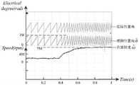
图4是电机零速起动升至200rpm时的实验波形图。Figure 4 is the experimental waveform diagram when the motor starts at zero speed and rises to 200rpm.
图5是电机转速由200rpm升至750rpm的实验波形图。Fig. 5 is the experimental waveform diagram of the motor speed rising from 200rpm to 750rpm.
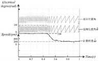
图6是电机转速由750rpm降至200rpm的实验波形图。Fig. 6 is an experimental waveform diagram of the motor speed decreasing from 750rpm to 200rpm.
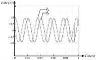
图7是电机转速在200rpm时的扩展反电动势波形图。Fig. 7 is the extended back electromotive force waveform diagram when the motor speed is 200rpm.
图8是电机转速在750rpm时的扩展反电动势波形图。Figure 8 is the extended back EMF waveform diagram when the motor speed is at 750rpm.
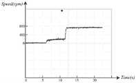
图9是电机转速从零速起动升至200rpm再升至750rpm的转速波形图。Fig. 9 is a waveform diagram of the motor speed rising from zero speed starting to 200rpm and then rising to 750rpm.
图10是电机转速从750rpm降至200rpm再降至0的转速波形图。Fig. 10 is a waveform diagram of the motor speed decreasing from 750rpm to 200rpm and then to 0.
具体实施方式detailed description
为了将本发明的实施方法与技术优势阐述得更加清晰易懂,下面结合附图对本发明的技术方案进行详细说明。In order to explain the implementation method and technical advantages of the present invention more clearly and easily, the technical solutions of the present invention will be described in detail below in conjunction with the accompanying drawings.
三相PMSM无位置控制的系统框图如图1所示,该系统的闭环控制主要包含转速外环,电流内环以及锁相环。给定转速ωref送入转速外环,与反馈转速


本发明所利用的一种扩展反电动势实时计算算法原理如图2所示。以凸极式PMSM为例,重写扩展反电动势观测模型:The principle of an extended counter electromotive force real-time calculation algorithm used in the present invention is shown in FIG. 2 . Taking the salient pole PMSM as an example, rewrite the extended back EMF observation model:

从式(8)中可知,要想求出扩展反电动势eα和eβ,需要输入的变量为uα、uβ、iα、iβ和ωe,其中,ωe可由锁相环估算的转速


式(9)中的


得到扩展反电动势实时计算算法所需的输入变量后,根据图2所示的扩展反电动势实时计算算法即可得到扩展反电动势的观测值

第一乘法器M1对α-β坐标系下的电机电流iα和定子绕组电阻Rs进行乘法运算,输出乘积结果至第一加法器A1;第二乘法器M2对α-β坐标系下的电机电流iβ和定子绕组电阻Rs进行乘法运算,输出乘积结果至第三加法器A3;第三乘法器M3对锁相环估算的电角速度


从该算法可以清楚得知,传统扩展反电动势中的电流微分项被ωeiα或ωeiβ取代,这样就避免了微分误差和迭代运算,使得位置角信息估算更准确。It can be clearly seen from the algorithm that the current differential term in the traditional extended back EMF is replaced by ωe iα or ωe iβ , which avoids differential errors and iterative operations, and makes the position angle information estimation more accurate.
本发明所利用的锁相环算法原理如图3所示,其具体描述为:The phase-locked loop algorithm principle that the present invention utilizes is as shown in Figure 3, and its specific description is:
第六乘法器M6对扩展反电动势观测器输出的


式(11)中
本发明所提出的零速或极低速恒流变频起动方法和起动阶段向中高速阶段柔性切换方法,具体描述为:The zero-speed or extremely low-speed constant-current variable-frequency starting method and the flexible switching method from the starting stage to the medium-high speed stage proposed by the present invention are specifically described as follows:
起动阶段,锁相环的切换信号K=0,向转速PI调节器输出限幅信号,从而限制起动电流,由于PI调节器在起动阶段饱和,所以输出电流恒定。此外,锁相环系统内部生成的起动给定斜坡转速ωstart做自加运算,可表示为:In the starting phase, the switching signal K of the phase-locked loop is 0, and the limiting signal is output to the PI regulator of the rotational speed, thereby limiting the starting current. Since the PI regulator is saturated in the starting phase, the output current is constant. In addition, the starting given ramp speed ωstart generated inside the phase-locked loop system is used for self-addition operation, which can be expressed as:
ωstart=ωstart′+atk (12)ωstart = ωstart ′+atk (12)
上式中,ωstart′为处理器上一次计算得到的给定转速值,tk为处理器计算周期,a为自增系数,在计算周期不变的情况下,a的取值决定了ωstart的增长速率。In the above formula, ωstart ′ is the given speed value calculated by the processor last time, tk is the calculation cycle of the processor, and a is the self-increment coefficient. When the calculation cycle remains unchanged, the value of a determines ω The growth rate ofstart .
在起动阶段,锁相环输出的观测位置角
设定ωstart=A时(A为转速切换阈值,可取10~30rad/s),锁相环系统进入切换点,内部生成切换信号K=1,此时锁相环输出的观测位置角


为验证本发明的实际有效性,本发明基于STM32数字控制器搭建实验平台进行验证。图4为4对极三相PMSM从0开始起动升速至200rpm的实验波形图,从图中可以清楚看到起动过程中,观测位置角很快就与实际位置角保持同相位,证明起动具有很好的可靠性。将起动阶段向中高速阶段过渡的切换点设置在100rpm,从图中可以看到,当观测转速达到100rpm后,短时间里有略微下降,说明锁相环跟踪的转速由ωstart变为
图5和图6分别给出了三相PMSM从200rpm升速至750rpm和从750rpm降速至200rpm的实验波形图。从两图中可得知,无论是升速还是降速,暂态过程只有约0.4s,证明本发明在调速过程的动态响应良好,且观测位置角始终与实际位置角同相位,证明本发明观测的位置信息精确,稳态性能良好。Figure 5 and Figure 6 show the experimental waveforms of three-phase PMSM speed up from 200rpm to 750rpm and speed down from 750rpm to 200rpm respectively. It can be seen from the two figures that the transient process is only about 0.4s whether it is speed up or down, which proves that the dynamic response of the present invention is good in the speed regulation process, and the observed position angle is always in the same phase as the actual position angle, which proves that the present invention The position information observed by the invention is accurate, and the steady-state performance is good.
图7和图8分别给出了三相PMSM在200rpm和750rpm时的扩展反电动势波形。从图中可以看出

图9和图10分别给出了三相PMSM从零升至200rpm再升至750rpm的转速图以及从750rpm降至200rpm再降至零速的转速图。从图中可以看到本发明在全速域无位置控制中兼顾动态响应和稳态精度,在中低端电机控制器中具有一定的工程应用价值。Fig. 9 and Fig. 10 respectively show the rotation speed diagram of the three-phase PMSM rising from zero to 200rpm to 750rpm and the rotation speed diagram from 750rpm to 200rpm and then to zero speed. It can be seen from the figure that the present invention takes both dynamic response and steady-state accuracy into account in the positionless control in the full speed range, and has certain engineering application value in low-end motor controllers.
以上实施例仅为说明本发明的技术思想,不能以此限定本发明的保护范围,凡是按照本发明提出的技术思想,在技术方案基础上所做的任何改动,均落入本发明保护范围之内。The above embodiments are only to illustrate the technical ideas of the present invention, and cannot limit the protection scope of the present invention with this. All technical ideas proposed according to the present invention, any changes made on the basis of technical solutions, all fall within the protection scope of the present invention. Inside.
Claims (8)


Priority Applications (1)
| Application Number | Priority Date | Filing Date | Title |
|---|---|---|---|
| CN202211143002.7ACN115514273A (en) | 2022-09-20 | 2022-09-20 | Full-speed-domain position-sensorless control method for three-phase permanent magnet synchronous motor |
Applications Claiming Priority (1)
| Application Number | Priority Date | Filing Date | Title |
|---|---|---|---|
| CN202211143002.7ACN115514273A (en) | 2022-09-20 | 2022-09-20 | Full-speed-domain position-sensorless control method for three-phase permanent magnet synchronous motor |
Publications (1)
| Publication Number | Publication Date |
|---|---|
| CN115514273Atrue CN115514273A (en) | 2022-12-23 |
Family
ID=84504414
Family Applications (1)
| Application Number | Title | Priority Date | Filing Date |
|---|---|---|---|
| CN202211143002.7APendingCN115514273A (en) | 2022-09-20 | 2022-09-20 | Full-speed-domain position-sensorless control method for three-phase permanent magnet synchronous motor |
Country Status (1)
| Country | Link |
|---|---|
| CN (1) | CN115514273A (en) |
Cited By (1)
| Publication number | Priority date | Publication date | Assignee | Title |
|---|---|---|---|---|
| CN118826563A (en)* | 2024-08-19 | 2024-10-22 | 浙江大学先进电气装备创新中心 | Position sensorless control method for high-speed permanent magnet synchronous motor based on prediction idea |
- 2022
- 2022-09-20CNCN202211143002.7Apatent/CN115514273A/enactivePending
Cited By (1)
| Publication number | Priority date | Publication date | Assignee | Title |
|---|---|---|---|---|
| CN118826563A (en)* | 2024-08-19 | 2024-10-22 | 浙江大学先进电气装备创新中心 | Position sensorless control method for high-speed permanent magnet synchronous motor based on prediction idea |
Similar Documents
| Publication | Publication Date | Title |
|---|---|---|
| CN107046387B (en) | Variable PID parameter current loop starting method of permanent magnet synchronous motor | |
| Gou et al. | Integral sliding mode control for starting speed sensorless controlled induction motor in the rotating condition | |
| CN102684592B (en) | Torque and flux linkage control method for permanent synchronous motor | |
| CN108155838A (en) | A kind of rotating speed method for tracing based on permanent magnet synchronous motor open loop | |
| CN107508521B (en) | A speed sensorless control method and system for a permanent magnet synchronous motor | |
| CN112671298B (en) | Improved PLL non-inductive control algorithm for permanent magnet synchronous motor control | |
| CN113676088B (en) | Speed sensorless control method of permanent magnet synchronous motor with harmonic suppression | |
| CN110429891B (en) | Position-sensor-free permanent magnet motor direct-drive power generation control method | |
| WO2022237829A1 (en) | Motor control method, control system, and storage medium | |
| CN110011587A (en) | A sensorless vector control method for permanent magnet synchronous motor based on multi-parameter identification | |
| CN108494308A (en) | A kind of control method of quick lock in asynchronous machine rotor frequency | |
| CN111181458A (en) | Surface-mounted permanent magnet synchronous motor rotor flux linkage observation method based on extended Kalman filter | |
| CN110971166A (en) | Obtaining method and control system of rotor position of permanent magnet synchronous generator | |
| CN108880377A (en) | A kind of method for estimating rotating speed of the permanent magnet synchronous motor based on novel phaselocked loop | |
| CN115242154B (en) | Self-adaptive smooth switching method for I-f starting to position sliding mode observer | |
| CN115514273A (en) | Full-speed-domain position-sensorless control method for three-phase permanent magnet synchronous motor | |
| CN113328659B (en) | PI parameter setting method for rotating speed ring of permanent magnet synchronous motor | |
| CN114465530A (en) | Speed control method and system of permanent magnet synchronous motor | |
| CN112865654A (en) | Torque maximum utilization control system and method for permanent magnet magnetic concentration type synchronous reluctance motor | |
| CN116208053B (en) | Control system and method for permanent magnet synchronous motor | |
| Liang et al. | A compensation method for rotor position estimation of PMSM based on pulsating high frequency injection | |
| CN115378333B (en) | Sliding mode angle self-adaptive compensation method based on current loop output | |
| CN102386839B (en) | Synchronous motor vector controller based on reactive power observer and control method | |
| CN116232158A (en) | SynRM high-quality resonance dead beat prediction current control method | |
| CN111800039B (en) | Rotor position information confirming method, vector control method and device of synchronous motor |
Legal Events
| Date | Code | Title | Description |
|---|---|---|---|
| PB01 | Publication | ||
| PB01 | Publication | ||
| SE01 | Entry into force of request for substantive examination | ||
| SE01 | Entry into force of request for substantive examination |