CN115493726B - Vacuum anti-magnetic levitation force detector and application method thereof - Google Patents
Vacuum anti-magnetic levitation force detector and application method thereofDownload PDFInfo
- Publication number
- CN115493726B CN115493726BCN202211461196.5ACN202211461196ACN115493726BCN 115493726 BCN115493726 BCN 115493726BCN 202211461196 ACN202211461196 ACN 202211461196ACN 115493726 BCN115493726 BCN 115493726B
- Authority
- CN
- China
- Prior art keywords
- suspended
- suspension
- magnetic
- force
- pendulum
- Prior art date
- Legal status (The legal status is an assumption and is not a legal conclusion. Google has not performed a legal analysis and makes no representation as to the accuracy of the status listed.)
- Active
Links
Images


Classifications
- G—PHYSICS
- G01—MEASURING; TESTING
- G01L—MEASURING FORCE, STRESS, TORQUE, WORK, MECHANICAL POWER, MECHANICAL EFFICIENCY, OR FLUID PRESSURE
- G01L1/00—Measuring force or stress, in general
- G—PHYSICS
- G01—MEASURING; TESTING
- G01L—MEASURING FORCE, STRESS, TORQUE, WORK, MECHANICAL POWER, MECHANICAL EFFICIENCY, OR FLUID PRESSURE
- G01L9/00—Measuring steady of quasi-steady pressure of fluid or fluent solid material by electric or magnetic pressure-sensitive elements; Transmitting or indicating the displacement of mechanical pressure-sensitive elements, used to measure the steady or quasi-steady pressure of a fluid or fluent solid material, by electric or magnetic means
- G01L9/14—Measuring steady of quasi-steady pressure of fluid or fluent solid material by electric or magnetic pressure-sensitive elements; Transmitting or indicating the displacement of mechanical pressure-sensitive elements, used to measure the steady or quasi-steady pressure of a fluid or fluent solid material, by electric or magnetic means involving the displacement of magnets, e.g. electromagnets
- G—PHYSICS
- G06—COMPUTING OR CALCULATING; COUNTING
- G06F—ELECTRIC DIGITAL DATA PROCESSING
- G06F30/00—Computer-aided design [CAD]
- G06F30/10—Geometric CAD
- G06F30/17—Mechanical parametric or variational design
- G—PHYSICS
- G06—COMPUTING OR CALCULATING; COUNTING
- G06F—ELECTRIC DIGITAL DATA PROCESSING
- G06F30/00—Computer-aided design [CAD]
- G06F30/20—Design optimisation, verification or simulation
- Y—GENERAL TAGGING OF NEW TECHNOLOGICAL DEVELOPMENTS; GENERAL TAGGING OF CROSS-SECTIONAL TECHNOLOGIES SPANNING OVER SEVERAL SECTIONS OF THE IPC; TECHNICAL SUBJECTS COVERED BY FORMER USPC CROSS-REFERENCE ART COLLECTIONS [XRACs] AND DIGESTS
- Y02—TECHNOLOGIES OR APPLICATIONS FOR MITIGATION OR ADAPTATION AGAINST CLIMATE CHANGE
- Y02P—CLIMATE CHANGE MITIGATION TECHNOLOGIES IN THE PRODUCTION OR PROCESSING OF GOODS
- Y02P10/00—Technologies related to metal processing
- Y02P10/25—Process efficiency
Landscapes
- Physics & Mathematics (AREA)
- Engineering & Computer Science (AREA)
- General Physics & Mathematics (AREA)
- Geometry (AREA)
- Theoretical Computer Science (AREA)
- Computer Hardware Design (AREA)
- Evolutionary Computation (AREA)
- General Engineering & Computer Science (AREA)
- Electromagnetism (AREA)
- Computational Mathematics (AREA)
- Mathematical Analysis (AREA)
- Mathematical Optimization (AREA)
- Pure & Applied Mathematics (AREA)
- Measuring Magnetic Variables (AREA)
Abstract
Description
Translated fromChinese技术领域Technical Field
本发明涉及超高精度力探测领域,涉及一种真空抗磁悬浮力探测器及其应用方法。The invention relates to the field of ultra-high precision force detection, and relates to a vacuum anti-magnetic suspension force detector and an application method thereof.
背景技术Background Art
机械振子已经被证实是一种有效的高灵敏度的力探测器,常见的机械振子包括原子力显微镜中常用到的悬臂梁、测万有引力用到的扭秤、测地球自转用到的傅科摆等等,它们都是利用机械振子放大待测信号,从而可以测得很微弱的信号。通过测量机械振子的运动可用来感知机械振子的受力。然而由于环境与机械振子接触,机械振子的运动不可避免地包含了环境的干扰,这限制了力探测精度。为了减少环境因素的干扰,真空悬浮机械振子应运而生,这样就最大限度地减少了环境与机械振子的接触,提高了机械振子的力探测灵敏度。常见的悬浮机制包括:光悬浮、保罗势阱悬浮、抗磁悬浮、超导磁悬浮、磁光混合悬浮等。悬浮的物体包括:磁体、金属、NV色心、石墨烯、二氧化硅等,这些物体被悬浮于势阱中,受束缚力作用具备一定的振动模式,因此称之为悬浮机械振子。悬浮机械振子作为力探测器具备很高的力探测灵敏度,可以进行一些极弱力的探测。Mechanical oscillators have been proven to be an effective and highly sensitive force detector. Common mechanical oscillators include cantilever beams commonly used in atomic force microscopes, torsion balances used to measure gravity, Foucault pendulums used to measure the rotation of the earth, etc. They all use mechanical oscillators to amplify the measured signal, so that very weak signals can be measured. The force on the mechanical oscillator can be sensed by measuring the movement of the mechanical oscillator. However, due to the contact between the environment and the mechanical oscillator, the movement of the mechanical oscillator inevitably contains environmental interference, which limits the accuracy of force detection. In order to reduce the interference of environmental factors, vacuum suspended mechanical oscillators came into being, which minimized the contact between the environment and the mechanical oscillator and improved the force detection sensitivity of the mechanical oscillator. Common suspension mechanisms include: optical suspension, Paul potential well suspension, anti-magnetic suspension, superconducting magnetic suspension, magneto-optical hybrid suspension, etc. Suspended objects include: magnets, metals, NV color centers, graphene, silicon dioxide, etc. These objects are suspended in the potential well and have certain vibration modes under the action of binding forces, so they are called suspended mechanical oscillators. As a force detector, the suspended mechanical oscillator has a high force detection sensitivity and can detect some extremely weak forces.
光悬浮机械振子俗称光镊,其原理是通过将激光聚焦后,由于光子的动量效应产生的势阱,具有极高的力灵敏度,但由于光镊需要外部能量输入,会给悬浮粒子带来加热和额外的光噪声,并且悬浮粒子大小限制在微米量级以下,不适用于大粒子的悬浮。保罗势阱悬浮则同样需要外部交变电流的能量输入。超导悬浮的应用被受限于其极低的工作环境。磁悬浮机械振子由于是被动稳定悬浮,同样具备极高的力灵敏度,并且可以悬浮毫米级别的大粒子,不受粒子大小的限制,不受低温的限制,很大程度上避免了上述悬浮系统的缺点,具有极大的应用前景。Optically suspended mechanical oscillators are commonly known as optical tweezers. Their principle is to focus the laser and generate a potential well due to the momentum effect of the photons. They have extremely high force sensitivity, but because optical tweezers require external energy input, they will cause heating and additional optical noise to the suspended particles, and the size of the suspended particles is limited to below the micron level, which is not suitable for the suspension of large particles. Paul potential well suspension also requires external alternating current energy input. The application of superconducting suspension is limited by its extremely low working environment. Magnetic levitation mechanical oscillators also have extremely high force sensitivity because they are passively and stably suspended, and can suspend large particles at the millimeter level. They are not limited by particle size or low temperature, and largely avoid the shortcomings of the above-mentioned suspension systems, and have great application prospects.
目前面临的问题:在短程力探测过程中,需要考虑到被探测对象与探测器之间除了待测力以外,还有一些表面力,比如静电力和卡西米尔力,它们会干扰力探测,因为这些干扰力都具备电磁性质,为了消除它们的干扰,通常的做法是在被探测对象与探测器之间加一层屏蔽膜屏蔽掉这些表面力,与此同时信号力不会被屏蔽。通常情况下,用于高精度探测器的悬浮系统势阱范围都很小从而影响屏蔽膜的加入。对于磁悬浮系统而言,通常悬浮力探测器都是一个抗磁机械振子悬浮于磁势阱内,屏蔽膜的加入势必会影响势阱处的场分布,从而影响悬浮性能。另一方面,磁悬浮机械振子束缚于势阱中,不便于靠近待测对象。这极大地限制了磁悬浮机械振子作为力探测器的实际应用。Current problems: In the process of short-range force detection, it is necessary to consider that in addition to the force to be measured, there are some surface forces between the detected object and the detector, such as electrostatic force and Casimir force, which will interfere with force detection. Because these interfering forces have electromagnetic properties, in order to eliminate their interference, the usual practice is to add a shielding film between the detected object and the detector to shield these surface forces, while the signal force will not be shielded. Usually, the potential well range of the suspension system used for high-precision detectors is very small, which affects the addition of shielding films. For magnetic suspension systems, the suspension force detector is usually an anti-magnetic mechanical oscillator suspended in a magnetic potential well. The addition of a shielding film will inevitably affect the field distribution at the potential well, thereby affecting the suspension performance. On the other hand, the magnetic suspension mechanical oscillator is bound in the potential well, which is not convenient for approaching the object to be measured. This greatly limits the practical application of magnetic suspension mechanical oscillators as force detectors.
发明内容Summary of the invention
针对现有技术存在的不足,本发明的目的是提供一种真空抗磁悬浮力探测器及其应用方法,以解决悬浮机械振子作为力探测器,受限于悬浮势阱,难以与被探测对象靠近,并且难以在探测器与被探测对象之间加屏蔽膜隔绝表面干扰力的问题。In view of the shortcomings of the prior art, the purpose of the present invention is to provide a vacuum anti-magnetic levitation force detector and an application method thereof, so as to solve the problem that a suspended mechanical oscillator is limited by the suspension potential well as a force detector and is difficult to get close to the object being detected, and it is difficult to add a shielding film between the detector and the object being detected to isolate the surface interference force.
为了解决上述问题,本发明把探测器结构设计成了悬浮摆状结构,使探测小球从束缚势阱中延伸出来,悬浮小球与探测小球用杆相连,这样既维持了探测小球的悬浮振子特性,又便于在探测小球与被探测物体之间添加足够大面积的屏蔽盾而不影响磁势阱。In order to solve the above problems, the present invention designs the detector structure into a suspended pendulum-like structure, so that the detection ball extends out from the bound potential well, and the suspended ball is connected to the detection ball by a rod. This not only maintains the suspended oscillator characteristics of the detection ball, but also makes it easy to add a shielding shield with a sufficiently large area between the detection ball and the detected object without affecting the magnetic potential well.
本发明采用的技术方案是:The technical solution adopted by the present invention is:
一种真空抗磁悬浮力探测器,包括:磁悬浮势阱、悬浮机械摆、A vacuum antimagnetic levitation force detector, comprising: a magnetic levitation potential well, a suspended mechanical pendulum,
真空腔、探测光路及外围电路;Vacuum cavity, detection optical path and peripheral circuits;
所述悬浮机械摆上端为抗磁材料,位于磁势阱中,为悬浮机械摆提供悬浮力,下端通过小杆与上端相连,小杆穿过磁悬浮势阱通孔,下端露出磁悬浮势阱;The upper end of the suspended mechanical pendulum is made of antimagnetic material and is located in the magnetic potential well to provide suspension force for the suspended mechanical pendulum. The lower end is connected to the upper end through a small rod. The small rod passes through the through hole of the magnetic suspension potential well, and the lower end is exposed to the magnetic suspension potential well.
真空腔包括温控系统、多级隔振系统,以及信号发生与处理模块、探测模块;The vacuum chamber includes a temperature control system, a multi-stage vibration isolation system, a signal generation and processing module, and a detection module;
温控系统使得真空腔保持恒温,多级隔振系统用于隔绝外界振动干扰,信号发生与处理模块用于调制解调力信号,探测模块用于探测所述悬浮机械摆的运动。The temperature control system enables the vacuum chamber to maintain a constant temperature, the multi-stage vibration isolation system is used to isolate external vibration interference, the signal generation and processing module is used to modulate and demodulate the force signal, and the detection module is used to detect the movement of the suspended mechanical pendulum.
所述磁悬浮势阱,其制备步骤是:The magnetic levitation potential well is prepared in the following steps:
步骤一:设计永磁铁构型,使所述的悬浮机械摆在三维空间稳定悬浮,并且预留小孔供悬浮机械摆穿过;Step 1: Design a permanent magnet configuration so that the suspension mechanical pendulum can be stably suspended in three-dimensional space, and reserve a small hole for the suspension mechanical pendulum to pass through;
步骤二:按照设计的永磁铁构型对永磁铁组件进行加工与充磁;Step 2: Processing and magnetizing the permanent magnet assembly according to the designed permanent magnet configuration;
步骤三:将加工与充磁好的永磁铁组件放入无磁性膜具中进行组装,并在模具中按照步骤一所述的设计调节好各个永磁铁组件之间的相对位置;Step 3: Place the processed and magnetized permanent magnet components into a non-magnetic mold for assembly, and adjust the relative positions of the permanent magnet components in the mold according to the design described in
步骤四:用环氧树脂将永磁铁组件粘牢封装。Step 4: Use epoxy resin to glue and encapsulate the permanent magnet assembly.
所述的步骤一,利用COMSOL或者ANSYS仿真软件模拟设计永磁铁构型。The first step is to use COMSOL or ANSYS simulation software to simulate and design the permanent magnet configuration.
所述的悬浮机械摆,包括:悬浮端、探头端,和中间的连接杆。The suspended mechanical pendulum comprises a suspended end, a probe end, and a connecting rod in the middle.
所述悬浮端,位于所述的磁势阱内,悬浮端具备抗磁性,平衡时,悬浮端在磁势阱中所受到的磁力等于整个悬浮机械摆的重力。The suspended end is located in the magnetic potential well and has anti-magnetic properties. When in equilibrium, the magnetic force received by the suspended end in the magnetic potential well is equal to the gravity of the entire suspended mechanical pendulum.
所述悬浮端,材料采用以下之一,包括聚甲基丙烯酸甲酯(PMMA)、金刚石、二氧化硅、热解石墨、铋;形状采用球体、块体或者圆柱体形状。The suspension end is made of one of the following materials, including polymethyl methacrylate (PMMA), diamond, silicon dioxide, pyrolytic graphite, and bismuth; and is shaped like a sphere, a block, or a cylinder.
所述探头端,位于磁势阱外,作为电场、磁场或者引力场的探针,The probe end is located outside the magnetic potential well and serves as a probe of the electric field, magnetic field or gravitational field.
探头端的形状采用以下形状之一:球体、圆柱体、锥体;The shape of the probe tip is one of the following: sphere, cylinder, cone;
探头端的材料根据待测物理量来确定,探测电场用带电金属,探测磁场用磁性材料,探测与质量相关的引力场用高密度材料。The material of the probe end is determined according to the physical quantity to be measured. Charged metal is used to detect electric fields, magnetic materials are used to detect magnetic fields, and high-density materials are used to detect gravitational fields related to mass.
所述悬浮端、探测端与杆组装或者一体化加工而成:The suspension end, the detection end and the rod are assembled or integrated into one:
在制备好悬浮端、探测端与杆后,在显微镜的辅助下,通过紫外胶将三者粘连在一起;或者After preparing the suspension end, the detection end and the rod, glue the three together with UV glue under the help of a microscope; or
通过微纳加工、微缩3D打印技术进行一体化加工;或者Integrated processing through micro-nano processing and micro-3D printing technology; or
利用光纤熔融技术一体化加工,方案如下:Using fiber fusion technology for integrated processing, the solution is as follows:
第一步:准备一根长度适中大小适中的光纤纤芯;Step 1: Prepare an optical fiber core of moderate length and size;
第二步:采用光纤熔接机在光纤两端各熔融出一个小球,熔融出的两个小球分别作为探头端和悬浮端,中间段的光纤纤芯则作为连接杆;Step 2: Use a fiber fusion splicer to fuse a small ball at each end of the optical fiber. The two fused balls serve as the probe end and the suspension end respectively, and the fiber core in the middle section serves as the connecting rod.
第三步:采用蒸镀工艺,在表面蒸镀一层亚微米厚度的金属薄膜,用于防静电。Step 3: Use the evaporation process to evaporate a sub-micron thick metal film on the surface for anti-static purposes.
所述探测光路及外围电路中:In the detection optical path and peripheral circuit:
探测光路部分包括:激光器、光纤、透镜、紫外灯;The detection optical path includes: laser, optical fiber, lens, and ultraviolet lamp;
外围电路部分包括:探测模块中的四象限光电探测器,以及信号发生与处理模块中的信号发生器、锁相放大器、信号处理模块;The peripheral circuit part includes: a four-quadrant photoelectric detector in the detection module, and a signal generator, a lock-in amplifier, and a signal processing module in the signal generation and processing module;
紫外灯照射在悬浮机械摆上,用于祛除悬浮机械摆所带的静电;The ultraviolet light is irradiated on the suspended mechanical pendulum to remove the static electricity carried by the suspended mechanical pendulum;
激光器发射出来的激光通过光纤准直、透镜汇聚后打在悬浮机械摆上,悬浮机械摆的散射光通过透镜收集后汇聚于四象限光电探测器上,以此探测悬浮机械摆的运动;The laser emitted by the laser is collimated by the optical fiber and converged by the lens to hit the suspended mechanical pendulum. The scattered light of the suspended mechanical pendulum is collected by the lens and converged on the four-quadrant photoelectric detector to detect the movement of the suspended mechanical pendulum.
信号发生器、锁相放大器和信号处理模块用于外加信号的调制解调。The signal generator, the phase-locked amplifier and the signal processing module are used for modulation and demodulation of the external signal.
一种所述的真空抗磁悬浮力探测器的应用方法,步骤如下:An application method of the vacuum anti-magnetic levitation force detector comprises the following steps:
步骤一:准备待测力信号发生模块,置于真空腔中,待测力用F表示;Step 1: Prepare the force signal generating module to be measured and place it in the vacuum chamber. The force to be measured is represented byF.
步骤二:准备所述抗磁悬浮力探测器,置于真空腔中;Step 2: prepare the anti-magnetic levitation force detector and place it in a vacuum chamber;
步骤三:使力发生模块产生的力信号作用于抗磁悬浮力探测器上,操作方式是,将力信号发生模块置于抗磁悬浮力探测器的金属屏蔽膜之下,通过特定的方式将力信号施加到力探测器的探测端;Step 3: Make the force signal generated by the force generating module act on the anti-magnetic levitation force detector. The operation method is to place the force signal generating module under the metal shielding film of the anti-magnetic levitation force detector and apply the force signal to the detection end of the force detector in a specific way;
步骤四:搭建探测光路,探测悬浮摆的运动位移ΔX,通过传递函数便能反推得到待测力大小:Step 4: Build a detection optical path to detect the motion displacement ΔX of the suspended pendulum. The magnitude of the force to be measured can be inferred through the transfer function:
F=ΔX/χ,F=ΔX/χ,
上式中χ代表悬浮机械摆的力到位移的传递函数;In the above formula, χ represents the force-to-displacement transfer function of the suspended mechanical pendulum;
所述步骤四具体实施步骤是:The specific implementation steps of
1)准备一个激光源,将激光源发出激光分为两束,一束作为参考光,另一束打在悬浮摆力探测器上;1) Prepare a laser source and split the laser light emitted by the laser source into two beams, one as the reference light and the other hitting the suspended pendulum force detector;
2) 用四象限光电探测器探测经过悬浮摆散射后的激光;2) Use a four-quadrant photodetector to detect the laser light scattered by the suspended pendulum;
3)对参考光功率与四象限光电探测器探测到的功率进行对照处理,获得悬浮物体的运动:3) Compare the reference light power with the power detected by the four-quadrant photoelectric detector to obtain the motion of the suspended object:
ΔX= ζΔV;ΔX = ζΔV;
其中V为四象限光电探测器探测到的相对于参考光探测器的电压,上式中,相对电压的变化为ΔV,悬浮摆的位移为ΔX,ζ为伏米系数,其数值通过热噪声标定、电场标定、磁场标定或者万有引力标定获得。Where V is the voltage detected by the four-quadrant photodetector relative to the reference photodetector. In the above formula, the change in relative voltage is ΔV, the displacement of the suspended pendulum is ΔX, and ζ is the volt-meter coefficient, whose value is obtained through thermal noise calibration, electric field calibration, magnetic field calibration or universal gravitation calibration.
本发明的有益效果是:The beneficial effects of the present invention are:
1、本发明通过悬浮摆的结构设计,将探头从磁势阱中延伸出来,便于在后续力测量过程中与被探测对象接近,也便于在探测对象与探测器之间加屏蔽膜而不会再干扰悬浮势阱的场分布。这将推进悬浮机械振子作为高精度力探测器的实际运用。1. The present invention extends the probe from the magnetic potential well through the structural design of the suspended pendulum, which makes it easier to approach the detected object during the subsequent force measurement process, and also makes it easier to add a shielding film between the detected object and the probe without interfering with the field distribution of the suspended potential well. This will promote the practical application of the suspended mechanical oscillator as a high-precision force detector.
2、本发明研发的悬浮摆利用抗磁系统悬浮,计算证明其能够被稳定悬浮并且具备一定的机械振动模式。如果使用其它的悬浮机制来悬浮机械摆,必然需要补充能量输入,将会引入额外的噪音,降低力探测灵敏度。而抗磁悬浮因为其被动悬浮机制,即使悬浮更重的东西也不需要额外的能量注入,不会引入额外噪音。2. The suspension pendulum developed by the present invention is suspended by an anti-magnetic system. Calculations have proven that it can be stably suspended and has a certain mechanical vibration mode. If other suspension mechanisms are used to suspend a mechanical pendulum, additional energy input is necessary, which will introduce additional noise and reduce the sensitivity of force detection. However, due to its passive suspension mechanism, anti-magnetic suspension does not require additional energy injection even when suspending heavier objects, and will not introduce additional noise.
附图说明BRIEF DESCRIPTION OF THE DRAWINGS
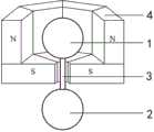
图1 为本发明一种真空抗磁悬浮力探测器在磁势阱中的悬浮示意图。FIG. 1 is a schematic diagram of the suspension of a vacuum anti-magnetic suspension force detector in a magnetic potential well according to the present invention.
图2 为本发明一种机械摆各个自由度示意简图。FIG. 2 is a schematic diagram showing the various degrees of freedom of a mechanical pendulum according to the present invention.
图3 为本发明一种真空抗磁悬浮力探测器的一种结构示意图。FIG. 3 is a schematic structural diagram of a vacuum anti-magnetic levitation force detector of the present invention.
图4 为本发明一种真空抗磁悬浮力探测器作为悬浮机械摆的原理示意图。FIG. 4 is a schematic diagram showing the principle of a vacuum antimagnetic levitation force detector according to the present invention as a suspended mechanical pendulum.
图5 为本发明一种真空抗磁悬浮力探测器对力的响应函数示意图。FIG. 5 is a schematic diagram of a response function of a vacuum anti-magnetic levitation force detector to force according to the present invention.
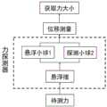
图6 为本发明的一种外力探测原理逻辑流程图。FIG. 6 is a logic flow chart of an external force detection principle of the present invention.
其中:1-悬浮小球;2-探头;3-连接杆;4-永磁铁;5-镀金层;6-金属屏蔽膜;7-探测对象。Among them: 1-suspended ball; 2-probe; 3-connecting rod; 4-permanent magnet; 5-gold-plated layer; 6-metal shielding film; 7-detection object.
具体实施方式DETAILED DESCRIPTION
以下结合附图和实施例对本发明作进一步阐述,特别说明,下述各种结构和形状为本发明的一个例子,不应将其视为本发明的全部或者视为对本发明的限定或者限制。The present invention is further described below in conjunction with the accompanying drawings and embodiments. It is particularly noted that the following various structures and shapes are an example of the present invention and should not be regarded as the entirety of the present invention or as a limitation or restriction to the present invention.
本实施例公开的一种真空抗磁悬浮力探测器,所有图例中的示意图仅是为了便于描述相关概念,并不与实际物体大小成正比。This embodiment discloses a vacuum anti-magnetic levitation force detector, and the schematic diagrams in all the illustrations are only for the convenience of describing related concepts and are not proportional to the actual size of the object.
一种真空抗磁悬浮力探测器,包括:磁悬浮势阱(如图1所示)、悬浮机械摆、真空腔、探测光路及外围电路;所述悬浮机械摆上端为抗磁材料,位于磁势阱中,为悬浮机械摆提供悬浮力,下端通过小杆与上端相连,小杆穿过磁悬浮势阱通孔,下端露出磁悬浮势阱;A vacuum anti-magnetic levitation force detector, comprising: a magnetic levitation potential well (as shown in FIG1 ), a levitation mechanical pendulum, a vacuum chamber, a detection optical path and a peripheral circuit; the upper end of the levitation mechanical pendulum is a diamagnetic material, located in the magnetic potential well, providing levitation force for the levitation mechanical pendulum, and the lower end is connected to the upper end through a small rod, the small rod passes through the through hole of the magnetic levitation potential well, and the lower end is exposed to the magnetic levitation potential well;
真空腔包括温控系统、多级隔振系统,以及信号发生与处理模块、探测模块;The vacuum chamber includes a temperature control system, a multi-stage vibration isolation system, a signal generation and processing module, and a detection module;
温控系统使得真空腔保持恒温,多级隔振系统用于隔绝外界振动干扰,信号发生与处理模块用于调制解调力信号,探测模块用于探测所述悬浮机械摆的运动。The temperature control system enables the vacuum chamber to maintain a constant temperature, the multi-stage vibration isolation system is used to isolate external vibration interference, the signal generation and processing module is used to modulate and demodulate the force signal, and the detection module is used to detect the movement of the suspended mechanical pendulum.
所述磁悬浮势阱,其制备步骤是:The magnetic levitation potential well is prepared in the following steps:
步骤一:利用COMSOL或者ANSYS仿真软件模拟设计永磁铁构型,使所述的悬浮机械摆在三维空间稳定悬浮,并且预留小孔供悬浮机械摆穿过;Step 1: Use COMSOL or ANSYS simulation software to simulate and design the permanent magnet configuration, so that the suspension mechanical pendulum can be stably suspended in three-dimensional space, and reserve a small hole for the suspension mechanical pendulum to pass through;
步骤二:按照设计的永磁铁构型对永磁铁组件进行加工与充磁;Step 2: Processing and magnetizing the permanent magnet assembly according to the designed permanent magnet configuration;
步骤三:将加工与充磁好的永磁铁组件放入无磁性膜具中进行组装,并在模具中按照步骤一所述的设计调节好各个永磁铁组件之间的相对位置;Step 3: Place the processed and magnetized permanent magnet components into a non-magnetic mold for assembly, and adjust the relative positions of the permanent magnet components in the mold according to the design described in
步骤四:用环氧树脂将永磁铁组件粘牢封装。Step 4: Use epoxy resin to glue and encapsulate the permanent magnet assembly.
所述的悬浮机械摆,包括:悬浮端、探头端,和中间的连接杆。The suspended mechanical pendulum comprises a suspended end, a probe end, and a connecting rod in the middle.
所述悬浮端,位于所述的磁势阱内,悬浮端具备抗磁性,平衡时,悬浮端在磁势阱中所受到的磁力等于整个悬浮机械摆的重力;The suspension end is located in the magnetic potential well, and has anti-magnetic properties. When in equilibrium, the magnetic force received by the suspension end in the magnetic potential well is equal to the gravity of the entire suspension mechanical pendulum;
材料采用以下之一,包括聚甲基丙烯酸甲酯(PMMA)、金刚石、二氧化硅、热解石墨、铋;The material is one of the following, including polymethyl methacrylate (PMMA), diamond, silicon dioxide, pyrolytic graphite, bismuth;
形状采用球体、块体或者圆柱体形状。The shape is a sphere, a block or a cylinder.
所述探头端,位于磁势阱外,作为电场、磁场或者引力场的探针;The probe end is located outside the magnetic potential well and serves as a probe of the electric field, magnetic field or gravitational field;
探头端的形状采用以下形状之一:球体、圆柱体、锥体;The shape of the probe tip is one of the following: sphere, cylinder, cone;
探头端的材料根据待测物理量来确定,探测电场用带电金属,探测磁场用磁性材料,探测与质量相关的引力场用高密度材料。The material of the probe end is determined according to the physical quantity to be measured. Charged metal is used to detect electric fields, magnetic materials are used to detect magnetic fields, and high-density materials are used to detect gravitational fields related to mass.
所述悬浮端、探测端与杆组装或者一体化加工而成:The suspension end, the detection end and the rod are assembled or integrated into one:
在制备好悬浮端、探测端与杆后,在显微镜的辅助下,通过紫外胶将三者粘连在一起;或者After preparing the suspension end, the detection end and the rod, glue the three together with UV glue under the help of a microscope; or
通过微纳加工、微缩3D打印技术进行一体化加工;或者利用光纤熔融技术一体化加工,方案如下:Integrated processing is carried out through micro-nano processing and micro-3D printing technology; or integrated processing is carried out using optical fiber melting technology. The scheme is as follows:
第一步:准备一根长度适中大小适中的光纤纤芯;Step 1: Prepare an optical fiber core of moderate length and size;
第二步:采用光纤熔接机在光纤两端各熔融出一个小球,熔融出的两个小球分别作为探头端和悬浮端,中间段的光纤纤芯则作为连接杆;Step 2: Use a fiber fusion splicer to fuse a small ball at each end of the optical fiber. The two fused balls serve as the probe end and the suspension end respectively, and the fiber core in the middle section serves as the connecting rod.
第三步:采用蒸镀工艺,在表面蒸镀一层亚微米厚度的金属薄膜,用于防静电。Step 3: Use the evaporation process to evaporate a sub-micron thick metal film on the surface for anti-static purposes.
所述探测光路及外围电路中:In the detection optical path and peripheral circuit:
探测光路部分包括:激光器、光纤、透镜、紫外灯;The detection optical path includes: laser, optical fiber, lens, and ultraviolet lamp;
外围电路部分包括:探测模块中的四象限光电探测器,以及信号发生与处理模块中的信号发生器、锁相放大器、信号处理模块;The peripheral circuit part includes: a four-quadrant photoelectric detector in the detection module, and a signal generator, a lock-in amplifier, and a signal processing module in the signal generation and processing module;
紫外灯照射在悬浮机械摆上,用于祛除悬浮机械摆所带的静电;The ultraviolet light is irradiated on the suspended mechanical pendulum to remove the static electricity carried by the suspended mechanical pendulum;
激光器发射出来的激光通过光纤准直、透镜汇聚后打在悬浮机械摆上,悬浮机械摆的散射光通过透镜收集后汇聚于四象限光电探测器上,以此探测悬浮机械摆的运动;The laser emitted by the laser is collimated by the optical fiber and converged by the lens to hit the suspended mechanical pendulum. The scattered light of the suspended mechanical pendulum is collected by the lens and converged on the four-quadrant photoelectric detector to detect the movement of the suspended mechanical pendulum.
信号发生器、锁相放大器和信号处理模块用于外加信号的调制解调。The signal generator, the phase-locked amplifier and the signal processing module are used for modulation and demodulation of the external signal.
一种所述的真空抗磁悬浮力探测器的应用方法,步骤如下:An application method of the vacuum anti-magnetic levitation force detector comprises the following steps:
步骤一:准备待测力信号发生模块,置于真空腔中,待测力用F表示;Step 1: Prepare the force signal generating module to be measured and place it in the vacuum chamber. The force to be measured is represented byF.
步骤二:准备所述抗磁悬浮力探测器,置于真空腔中;Step 2: prepare the anti-magnetic levitation force detector and place it in a vacuum chamber;
步骤三:使力发生模块产生的力信号作用于抗磁悬浮力探测器上,操作方式是,将力信号发生模块置于抗磁悬浮力探测器的金属屏蔽膜之下,通过特定的方式将力信号施加到力探测器的探测端,注意:若待测信号是电场或者磁场则无需添加相应的屏蔽膜,以免屏蔽待测信号;Step 3: Make the force signal generated by the force generating module act on the anti-magnetic levitation force detector. The operation method is to place the force signal generating module under the metal shielding film of the anti-magnetic levitation force detector, and apply the force signal to the detection end of the force detector in a specific way. Note: if the signal to be measured is an electric field or a magnetic field, there is no need to add a corresponding shielding film to avoid shielding the signal to be measured;
步骤四:搭建探测光路,探测悬浮摆的运动位移ΔX,通过传递函数便能反推得到待测力大小:Step 4: Build a detection optical path to detect the motion displacement ΔX of the suspended pendulum. The magnitude of the force to be measured can be inferred through the transfer function:
F=ΔX/χ,F=ΔX/χ,
上式中χ代表悬浮机械摆的力到位移的传递函数;In the above formula, χ represents the force-to-displacement transfer function of the suspended mechanical pendulum;
所述步骤四具体实施步骤是:The specific implementation steps of
1)准备一个激光源,将激光源发出激光分为两束,一束作为参考光,另一束打在悬浮摆力探测器上;1) Prepare a laser source and split the laser light emitted by the laser source into two beams, one as the reference light and the other hitting the suspended pendulum force detector;
2)用四象限光电探测器探测经过悬浮摆散射后的激光;2) Use a four-quadrant photodetector to detect the laser light scattered by the suspended pendulum;
3)对参考光功率与四象限光电探测器探测到的功率进行对照处理,获得悬浮物体的运动:3) Compare the reference light power with the power detected by the four-quadrant photoelectric detector to obtain the motion of the suspended object:
ΔX= ζΔV;ΔX = ζΔV;
其中V为四象限光电探测器探测到的相对于参考光探测器的电压,上式中,相对电压的变化为ΔV,悬浮摆的位移为ΔX,ζ为伏米系数,其数值通过热噪声标定、电场标定、磁场标定或者万有引力标定获得。Where V is the voltage detected by the four-quadrant photodetector relative to the reference photodetector. In the above formula, the change in relative voltage is ΔV, the displacement of the suspended pendulum is ΔX, and ζ is the volt-meter coefficient, whose value is obtained through thermal noise calibration, electric field calibration, magnetic field calibration or universal gravitation calibration.
应用实施例Application Examples
基于本实例运用于精密力探测的具体的实施步骤是:The specific implementation steps for precision force detection based on this example are:
第一步,磁悬浮势阱的设计与组装:The first step is the design and assembly of the magnetic levitation potential well:
首先利用COMSOL或者ANSYS等仿真软件模拟设计永磁铁结构,在设计永磁铁结构的First, use simulation software such as COMSOL or ANSYS to simulate and design the permanent magnet structure.
过程中要求保证所选的悬浮摆够在三维空间稳定悬浮,并且需要预留小孔供悬浮摆穿过,保证探测端伸出磁势阱。设计了如图1所示的永磁铁4,所述永磁铁4为力探测器提供抗磁悬浮势阱,它是由上下两层,每层8块梯形磁体构成,每层都预留通孔,上层通孔为束缚区,为悬浮小球1提供抗磁力,悬浮小球1受到悬浮力,用来抵抗悬浮小球1、连接杆3和探头2的重力,下层通孔使得连接杆3能够自由伸出磁势阱。The process requires that the selected suspension pendulum can be stably suspended in three-dimensional space, and a small hole needs to be reserved for the suspension pendulum to pass through, so as to ensure that the detection end extends out of the magnetic potential well. A
然后按照设定的构型对永磁铁组件进行加工与充磁。Then the permanent magnet assembly is processed and magnetized according to the set configuration.
将加工好的磁铁按照设计的方式进行组装。Assemble the processed magnets as designed.
用环氧树脂或者其它高真空适用的胶水将永磁铁组件粘牢封装,实现磁悬浮势阱制备。The permanent magnet assembly is glued and packaged with epoxy resin or other high vacuum-suitable glue to realize the preparation of magnetic levitation potential well.
第二步,悬浮摆振动模式建模:The second step is to model the vibration mode of the suspended pendulum:
设计悬浮摆需要计算出它各个自由度的振动模式,以便根据具体应用选取合适的大小、形状以及材料的悬浮小球、连接杆和探头,对悬浮摆振动模式建模:Designing a suspended pendulum requires calculating the vibration modes of each degree of freedom, so as to select the appropriate size, shape and material of the suspended ball, connecting rod and probe according to the specific application, and model the vibration mode of the suspended pendulum:
所述的磁势阱通过钕铁硼永磁体4提供,磁势阱沿

如图2所示,悬浮机械摆具有5个自由度,包括:质心坐标

其中


其中


解运动方程组,即可得到悬浮摆的各个运动模式。为了简化运动模式的求解,在此给出一组特殊参数的悬浮摆振动模式的解:Solving the set of motion equations, we can get the various motion modes of the suspended pendulum. In order to simplify the solution of the motion mode, a set of solutions to the vibration modes of the suspended pendulum with special parameters is given here:
当

其中a、b、c满足:Where a, b, and c satisfy:


第三步,悬浮摆的制备:Step 3: Preparation of the suspended pendulum:
如图3所示力探测器包括悬浮小球1、探头2、连接杆3,其中,探头2、连接杆3镀有表面镀金层4。所述悬浮小球1需具备抗磁性,用来提供整个力探测器的悬浮力;所述探头2是一个小球或者其它构型;所述连接杆3用以连接悬浮小球1和探头2,连接杆3具备刚性,悬浮摆在振动过程中其形变可忽略;所述表面镀金层5可采用蒸镀的方法蒸镀于探头2与连接杆3上。具体操作如下:As shown in Figure 3, the force detector includes a suspended
根据理论计算好的参数,在制备好悬浮端、探测端与杆后,便可以制备悬浮摆:可以在显微镜和其它加持设备的辅助下,通过紫外胶将三者粘连在一起。也可以用微纳加工或者微缩3D打印技术实现一体化加工。还可以用其它方式实现一体化加工,比如利用光纤熔融技术,具体方案如下:首先准备一根长度适中大小适中的光纤纤芯;然后采用激光熔切机在光纤两端各熔融出一个小球,熔融出的小球作为探头端和悬浮端;最后采用蒸镀工艺,在表面蒸镀一层亚微米厚度的金属薄膜,以达到防静电作用。According to the parameters calculated theoretically, after preparing the suspension end, the detection end and the rod, the suspension pendulum can be prepared: with the help of a microscope and other supporting equipment, the three can be glued together with UV glue. Micro-nano processing or micro-3D printing technology can also be used to achieve integrated processing. Integrated processing can also be achieved in other ways, such as using fiber fusion technology. The specific plan is as follows: first prepare a fiber core of moderate length and size; then use a laser melting machine to melt a small ball at each end of the fiber, and the melted small ball is used as the probe end and the suspension end; finally, a vapor deposition process is used to evaporate a layer of sub-micron thick metal film on the surface to achieve anti-static effect.
第四步,制备屏蔽膜:Step 4: Prepare shielding film:
屏蔽膜用以屏蔽探测过程中的电磁力干扰,其制作步骤是:微纳机械加工一块氮化硅薄膜;微纳机械加工一个氮化硅薄膜适配框架;将氮化硅薄膜固定安装在薄膜框架上。The shielding film is used to shield electromagnetic interference during the detection process, and its production steps are: micro-nano machining a silicon nitride film; micro-nano machining a silicon nitride film adaptation frame; and fixing the silicon nitride film on the film frame.
第五步,外围光路电路以及真空腔的设计:Step 5: Design of peripheral optical circuit and vacuum cavity:
根据探测需求设计好外围光路电路以及真空腔,其中光路部分包括:激光器、光纤、各类波片、透镜、紫外灯,以及其他光学器件;电路部分包括:电源、电线、四象限光电探测器、信号发生器、信号处理模块、锁相放大器、FPGA模块以及其他电子器件。Design the peripheral optical path circuit and vacuum cavity according to the detection requirements. The optical path part includes: lasers, optical fibers, various wave plates, lenses, ultraviolet lamps, and other optical devices; the circuit part includes: power supply, wires, four-quadrant photodetectors, signal generators, signal processing modules, phase-locked amplifiers, FPGA modules and other electronic devices.
真空腔内各个器件的安装与排布需要按照要求设计好,其中还需包括温控系统、隔振系统、信号发生模块、探测模块等等。The installation and arrangement of each device in the vacuum chamber need to be designed according to the requirements, which also include temperature control system, vibration isolation system, signal generation module, detection module, etc.
第六步,悬浮摆的捕获以及信号装置的添加:Step 6: Capture of the suspended pendulum and addition of the signal device:
悬浮摆的捕获:可根据悬浮摆的尺寸可以采取不同的方式将探测器悬于磁势阱中,常Capture of suspended pendulum: The detector can be suspended in the magnetic potential well in different ways according to the size of the suspended pendulum.
用的方式为利用加持系统在显微镜的辅助下缓慢将悬浮摆置于磁势阱中,为防止静电力的干扰,此过程可事先做去静电处理,比如紫外灯的照射。The method used is to use a holding system to slowly place the suspended pendulum in the magnetic potential well with the assistance of a microscope. To prevent interference from electrostatic forces, this process can be preceded by anti-static treatment, such as irradiation with ultraviolet light.
信号装置的添加:将制备好的信号装置(比如用压电陶瓷驱动的密度周期性排布的质量块)安装在探头2的下方,调节好信号装置与探头2之间的距离。在探头2与探测对象7之间放置金属屏蔽膜6,用以隔绝探头2与待测对象7之间的表面力干扰。Adding the signal device: Install the prepared signal device (such as a density-periodically arranged mass block driven by piezoelectric ceramics) under the
第七步,位移与力的探测:Step 7: Detection of displacement and force:
所述探测对象7产生待测力作用于探头2上,在探头2与探测对象7之间架好金属屏蔽膜6,用以屏蔽表面力干扰。如若探测静电力,则无需添加静电屏蔽膜,如若像原子力显微镜那样探测物体表面形态,则可以不添加任何屏蔽膜。The detected
如图4所示,当外界力(比如由7产生的万有引力或者电场力)作用在探头2上,若周期性调制万有引力,则悬浮摆就会摆动起来,通过测量悬浮摆的振幅大小以及其它相关参数,便能反应被探测力的大小。As shown in FIG4 , when an external force (such as the gravitational force or electric field force generated by 7 ) acts on the
为此需要计算在外力F的作用下,悬浮端小球1和探测端探头2的振幅各式多少,即分别计算他们的传递函数,这样就可以通过振幅反推力。To this end, it is necessary to calculate the amplitudes of the suspended
悬浮摆具备机械振动模式,具备力探测能力,设施加在探测端探针上的力为F0,通过对其运动方程进行傅里叶变换后求解线性方程组可分别得到悬浮端小球1和探测端探头2对正弦函数力F0的响应,设悬浮端和探测端响应的振幅分别为A1和A2,则其力传递函数分别为:The suspended pendulum has a mechanical vibration mode and force detection capability. The force applied to the probe at the detection end is F0 . By performing Fourier transform on its motion equation and solving the linear equations, the responses of the suspended


图5表示悬浮端小球1和探测端探头2对外力的响应函数。正弦函数外力为F0,悬浮端的振幅为A1,探头2的振幅为A2,悬浮小球1的力响应函数为

图6表示外力探测的原理逻辑流程:外力作用于探头2上,会影响悬浮摆的运动,悬浮摆的运动体现在悬浮小球1或者探头2上,通过读取悬浮小球1或者探头2的位移从而推导出外力的大小。具体做法为:Figure 6 shows the principle logic flow of external force detection: the external force acts on the
将入射激光光纤对准悬浮小球1,透射的激光用四象限光电探测器探测,根据四象限光电探测器各个象限探测的功率以及悬浮摆的伏米系数可解析出悬浮端小球1在各个方向的运动,根据计算出来的传递函数

第七步也可以根据需求替换成第八步。
第八步,位移与力的探测:Step 8: Detection of displacement and force:
将入射激光光纤对探测端小球2,透射的激光用四象限光电探测器探测,根据四象限光电探测器各个象限探测的功率以及悬浮摆的伏米系数可解析出探测端小球2在各个方向的运动,根据计算出来的传递函数

以上所述实施例仅表达了本发明的几种实施方式,其描述较为具体和详细,但并不能因此而理解为对发明范围的限制。应当指出的是,对于本领域的普通技术人员来说,在不脱离本发明构思的前提下,还可以做出若干变形和改进,这些都属于本发明的保护范围。因此,本发明的保护范围应以所附权利要求为准。The above-described embodiments only express several implementation methods of the present invention, and the description thereof is relatively specific and detailed, but it cannot be understood as limiting the scope of the invention. It should be pointed out that, for a person of ordinary skill in the art, several modifications and improvements can be made without departing from the concept of the present invention, and these all belong to the protection scope of the present invention. Therefore, the protection scope of the present invention shall be subject to the attached claims.
Claims (5)
Translated fromChinesePriority Applications (1)
| Application Number | Priority Date | Filing Date | Title |
|---|---|---|---|
| CN202211461196.5ACN115493726B (en) | 2022-11-16 | 2022-11-16 | Vacuum anti-magnetic levitation force detector and application method thereof |
Applications Claiming Priority (1)
| Application Number | Priority Date | Filing Date | Title |
|---|---|---|---|
| CN202211461196.5ACN115493726B (en) | 2022-11-16 | 2022-11-16 | Vacuum anti-magnetic levitation force detector and application method thereof |
Publications (2)
| Publication Number | Publication Date |
|---|---|
| CN115493726A CN115493726A (en) | 2022-12-20 |
| CN115493726Btrue CN115493726B (en) | 2023-05-05 |
Family
ID=85114767
Family Applications (1)
| Application Number | Title | Priority Date | Filing Date |
|---|---|---|---|
| CN202211461196.5AActiveCN115493726B (en) | 2022-11-16 | 2022-11-16 | Vacuum anti-magnetic levitation force detector and application method thereof |
Country Status (1)
| Country | Link |
|---|---|
| CN (1) | CN115493726B (en) |
Citations (18)
| Publication number | Priority date | Publication date | Assignee | Title |
|---|---|---|---|---|
| US5638340A (en)* | 1996-04-15 | 1997-06-10 | Schiefele; Walter P. | Clock having magnetically-levitated pendulum |
| CN1784176A (en)* | 2003-05-09 | 2006-06-07 | 西门子公司 | Automatic balancing system for a tomography device |
| CN103273168A (en)* | 2013-04-25 | 2013-09-04 | 常州富通焊业有限公司 | Tungsten carbide suspended bead welding method and device |
| CN105775169A (en)* | 2016-03-21 | 2016-07-20 | 中国空间技术研究院 | Magnetization suspension induction drive type counteractive momentum ball |
| CN109113929A (en)* | 2018-09-04 | 2019-01-01 | 曲阜师范大学 | A kind of wind-force magnetic suspension cabin suspension control method |
| CN110231662A (en)* | 2019-06-21 | 2019-09-13 | 华中科技大学 | A kind of preparation method of the MEMS inertial sensor to be suspended based on diamagnetic body |
| KR102036761B1 (en)* | 2018-07-18 | 2019-10-25 | 국방과학연구소 | Superconducting gravity sensor |
| CN110782758A (en)* | 2019-12-05 | 2020-02-11 | 上海图菱新能源科技有限公司 | Magnetic suspension analytic experiment system and method |
| WO2021248698A1 (en)* | 2020-06-12 | 2021-12-16 | 浙江大学 | Absolute gravity meter based on optical tweezers in vacuum, and measurement method |
| CN215224120U (en)* | 2021-04-19 | 2021-12-21 | 威海宏阳仿生科技有限公司 | Magnetic suspension road sub-bait carrying coil conductor to generate vortex electric field |
| CN113917552A (en)* | 2021-08-27 | 2022-01-11 | 南京蓝色引力科技有限公司 | High-precision magnetic suspension relative gravimeter, control method and application |
| WO2022011813A1 (en)* | 2020-07-13 | 2022-01-20 | 李曼丽 | Multi-dimensional control suspension switch |
| WO2022055564A2 (en)* | 2020-05-14 | 2022-03-17 | Rochester Institute Of Technology | Optical tweezer phonon laser |
| CN114295257A (en)* | 2021-12-29 | 2022-04-08 | 河海大学 | A force sensor based on the principle of diamagnetic levitation and its measurement method |
| WO2022121116A1 (en)* | 2020-12-08 | 2022-06-16 | 之江实验室 | Optical tweezer and spin defect-based multi-physical parameter sensing device and method |
| CN114910662A (en)* | 2022-04-26 | 2022-08-16 | 浙江大学 | Device and method for realizing suspended microspheres in high vacuum environment by combining magnetic trap and optical trap |
| CN115079737A (en)* | 2022-07-22 | 2022-09-20 | 之江实验室 | Gravitational acceleration modulation device and method |
| CN115223430A (en)* | 2022-09-19 | 2022-10-21 | 之江实验室 | A vacuum optical tweezers experimental teaching device based on suspended nanoparticles |
Family Cites Families (2)
| Publication number | Priority date | Publication date | Assignee | Title |
|---|---|---|---|---|
| US8559023B2 (en)* | 2009-03-24 | 2013-10-15 | Harbin Institute Of Technology | Micro focal-length collimation based micro-cavity measuring method and detecting equipment thereof |
| US10754059B2 (en)* | 2018-03-09 | 2020-08-25 | Sri International | Compact and highly sensitive gravity gradiometer |
- 2022
- 2022-11-16CNCN202211461196.5Apatent/CN115493726B/enactiveActive
Patent Citations (18)
| Publication number | Priority date | Publication date | Assignee | Title |
|---|---|---|---|---|
| US5638340A (en)* | 1996-04-15 | 1997-06-10 | Schiefele; Walter P. | Clock having magnetically-levitated pendulum |
| CN1784176A (en)* | 2003-05-09 | 2006-06-07 | 西门子公司 | Automatic balancing system for a tomography device |
| CN103273168A (en)* | 2013-04-25 | 2013-09-04 | 常州富通焊业有限公司 | Tungsten carbide suspended bead welding method and device |
| CN105775169A (en)* | 2016-03-21 | 2016-07-20 | 中国空间技术研究院 | Magnetization suspension induction drive type counteractive momentum ball |
| KR102036761B1 (en)* | 2018-07-18 | 2019-10-25 | 국방과학연구소 | Superconducting gravity sensor |
| CN109113929A (en)* | 2018-09-04 | 2019-01-01 | 曲阜师范大学 | A kind of wind-force magnetic suspension cabin suspension control method |
| CN110231662A (en)* | 2019-06-21 | 2019-09-13 | 华中科技大学 | A kind of preparation method of the MEMS inertial sensor to be suspended based on diamagnetic body |
| CN110782758A (en)* | 2019-12-05 | 2020-02-11 | 上海图菱新能源科技有限公司 | Magnetic suspension analytic experiment system and method |
| WO2022055564A2 (en)* | 2020-05-14 | 2022-03-17 | Rochester Institute Of Technology | Optical tweezer phonon laser |
| WO2021248698A1 (en)* | 2020-06-12 | 2021-12-16 | 浙江大学 | Absolute gravity meter based on optical tweezers in vacuum, and measurement method |
| WO2022011813A1 (en)* | 2020-07-13 | 2022-01-20 | 李曼丽 | Multi-dimensional control suspension switch |
| WO2022121116A1 (en)* | 2020-12-08 | 2022-06-16 | 之江实验室 | Optical tweezer and spin defect-based multi-physical parameter sensing device and method |
| CN215224120U (en)* | 2021-04-19 | 2021-12-21 | 威海宏阳仿生科技有限公司 | Magnetic suspension road sub-bait carrying coil conductor to generate vortex electric field |
| CN113917552A (en)* | 2021-08-27 | 2022-01-11 | 南京蓝色引力科技有限公司 | High-precision magnetic suspension relative gravimeter, control method and application |
| CN114295257A (en)* | 2021-12-29 | 2022-04-08 | 河海大学 | A force sensor based on the principle of diamagnetic levitation and its measurement method |
| CN114910662A (en)* | 2022-04-26 | 2022-08-16 | 浙江大学 | Device and method for realizing suspended microspheres in high vacuum environment by combining magnetic trap and optical trap |
| CN115079737A (en)* | 2022-07-22 | 2022-09-20 | 之江实验室 | Gravitational acceleration modulation device and method |
| CN115223430A (en)* | 2022-09-19 | 2022-10-21 | 之江实验室 | A vacuum optical tweezers experimental teaching device based on suspended nanoparticles |
Non-Patent Citations (2)
| Title |
|---|
| 丁建桥 ; 张坤 ; 张振宇 ; 苏宇锋 ; 段智勇 ; .抗磁悬浮石墨转子理论及仿真分析.传感技术学报.2018,(第02期),全文.* |
| 闫兆盈 ; 刘坤 ; 杨文姣 ; 叶常青 ; 王瑞晨 ; 马光同 ; .高温超导体在强磁外场下的磁悬浮性能仿真研究.低温物理学报.2018,(第04期),全文.* |
Also Published As
| Publication number | Publication date |
|---|---|
| CN115493726A (en) | 2022-12-20 |
Similar Documents
| Publication | Publication Date | Title |
|---|---|---|
| CN113484538B (en) | Acceleration measurement method based on anti-magnetic suspension mechanical system | |
| CN101113896A (en) | Magnetic levitation device and measurement method for measuring spherical rotor pole axis deflection angle | |
| Chen et al. | Fiber-optic Sagnac interferometry for gravity gradient measurements | |
| JP2005537466A (en) | Diamagnetic levitation system | |
| Zhu et al. | Revolution of a trapped particle in counter-propagating dual-beam optical tweezers under low pressure | |
| CN105675920A (en) | High-precision static magnetic suspension accelerometer | |
| CN111750778A (en) | Particle position detection device and precision improvement method based on dual optical tweezers system | |
| CN114910662A (en) | Device and method for realizing suspended microspheres in high vacuum environment by combining magnetic trap and optical trap | |
| CN105738653A (en) | High-precision optical displacement magnetic suspension accelerometer | |
| CN109870592A (en) | An optical accelerometer driven by electromagnetic force | |
| CN113375637B (en) | Inclination angle sensor based on anti-magnetic suspension principle and measuring method thereof | |
| CN108897057A (en) | The full tensor gradiometry method and gravity gradiometer to be suspended based on luminous power | |
| CN115493726B (en) | Vacuum anti-magnetic levitation force detector and application method thereof | |
| Wang et al. | A diamagnetic levitation based inertial sensor for geophysical application | |
| CN110231664B (en) | A MEMS Inertial Sensor Based on Antimagnetic Suspension | |
| Marrara et al. | Optical calibration of holographic acoustic tweezers | |
| CN117471563B (en) | Suspended pendulum vibration isolation device, gravitational constant measuring device and measuring method thereof | |
| CN101320530A (en) | The fiber optic gyroscope structure of the north finder in the teaching experiment of fiber optic gyroscope | |
| CN115718204A (en) | Ferromagnetic diamagnetic mixed suspension directional acceleration measurement method | |
| CN110231663B (en) | Inertial sensor based on diamagnetic body suspension | |
| CN116973596B (en) | A magnetic-static hybrid suspension accelerometer and its measurement method | |
| CN110514191B (en) | Micro-computer electro-optical suspension rotary microparticle gyroscope | |
| CN115864897A (en) | Three-dimensional magnetic suspension structure of diamagnetic particles | |
| Zhu et al. | Suppression of damping in a diamagnetically levitated dielectric sphere via eddy currents and static charge reduction | |
| Barrot et al. | Acceleration sensor based on diamagnetic levitation |
Legal Events
| Date | Code | Title | Description |
|---|---|---|---|
| PB01 | Publication | ||
| PB01 | Publication | ||
| SE01 | Entry into force of request for substantive examination | ||
| SE01 | Entry into force of request for substantive examination | ||
| GR01 | Patent grant | ||
| GR01 | Patent grant |