CN115493682A - Method for rapidly judging faults of analog quantity sensor weighing system - Google Patents
Method for rapidly judging faults of analog quantity sensor weighing systemDownload PDFInfo
- Publication number
- CN115493682A CN115493682ACN202110682095.XACN202110682095ACN115493682ACN 115493682 ACN115493682 ACN 115493682ACN 202110682095 ACN202110682095 ACN 202110682095ACN 115493682 ACN115493682 ACN 115493682A
- Authority
- CN
- China
- Prior art keywords
- sensor
- output
- channel
- control unit
- input
- Prior art date
- Legal status (The legal status is an assumption and is not a legal conclusion. Google has not performed a legal analysis and makes no representation as to the accuracy of the status listed.)
- Pending
Links
- 238000005303weighingMethods0.000titleclaimsabstractdescription58
- 238000000034methodMethods0.000titleclaimsabstractdescription19
- 230000002159abnormal effectEffects0.000claimsdescription9
- 229910000831SteelInorganic materials0.000description5
- 239000010959steelSubstances0.000description5
- XEEYBQQBJWHFJM-UHFFFAOYSA-NIronChemical compound[Fe]XEEYBQQBJWHFJM-UHFFFAOYSA-N0.000description4
- 238000010586diagramMethods0.000description3
- 238000012423maintenanceMethods0.000description3
- 238000005516engineering processMethods0.000description2
- 229910052742ironInorganic materials0.000description2
- 238000009749continuous castingMethods0.000description1
- 238000005259measurementMethods0.000description1
- 238000010079rubber tappingMethods0.000description1
- 238000009628steelmakingMethods0.000description1
- 238000006467substitution reactionMethods0.000description1
- 230000009466transformationEffects0.000description1
- 238000000844transformationMethods0.000description1
- 239000002699waste materialSubstances0.000description1
Images

Classifications
- G—PHYSICS
- G01—MEASURING; TESTING
- G01G—WEIGHING
- G01G23/00—Auxiliary devices for weighing apparatus
- G01G23/01—Testing or calibrating of weighing apparatus
Landscapes
- Physics & Mathematics (AREA)
- General Physics & Mathematics (AREA)
- Safety Devices In Control Systems (AREA)
Abstract
Description
Translated fromChinese技术领域technical field
本发明涉及一种判断故障的方法,涉及工业企业生产的工艺和设备技术,适用于钢铁企业及其它相应工业领域。The invention relates to a method for judging faults, relates to the technology and equipment technology produced by industrial enterprises, and is applicable to iron and steel enterprises and other corresponding industrial fields.
背景技术Background technique
炼钢厂多处使用4个传感器的模拟量称重系统,如钢水称重、铁包称重、行车称重、连铸大包称重、中包称重等,用来完成各个工艺阶段所需要的重量计量功能,给操作人员的各阶段操作提供重量依据。称重系统的功能对于出钢、浇钢有很重要的参考意义,是操作人员判断钢水是否出尽、钢包是否浇注完毕的重要依据,因此,保证称重系统完好性是减少钢水浪费的重要手段。因此,这些地方的称重系统一旦发生故障,就要求快速找到原因,快速恢复使用。The analog weighing system with 4 sensors is used in many places in the steelmaking plant, such as molten steel weighing, iron ladle weighing, driving weighing, continuous casting ladle weighing, tundish weighing, etc., to complete all process steps The required weight measurement function provides weight basis for operators at each stage of operation. The function of the weighing system has very important reference significance for tapping and pouring steel. It is an important basis for operators to judge whether the molten steel is exhausted and whether the ladle is poured. Therefore, ensuring the integrity of the weighing system is an important means to reduce the waste of molten steel . Therefore, once the weighing system in these places fails, it is required to find the cause quickly and restore it to use quickly.
发明内容Contents of the invention
本发明正是针对现有技术中存在的问题,提供一种快速判断模拟量传感器称重系统故障的方法,该技术方案针对称重系统的故障检修依赖检修人员技能水平高,检修效率不高的难题,设计了专用的控制单元,上面设有拨码开关,不再需要检修人员拆接线,只需按说明操作拨码开关即可。操作简单,效率高,对检修人员技能要求不高。该方案采用在传感器和接线盒中间串入专用控制单元,通过拨码开关实现传感器的断开/接入、通道互换等功能,能够快速检测出故障原因,并临时维持使用。The present invention is aimed at the problems existing in the prior art, and provides a method for quickly judging the failure of the weighing system of the analog sensor. To solve the problem, a dedicated control unit is designed with a dial switch on it, so that maintenance personnel no longer need to disassemble the wiring, just operate the dial switch according to the instructions. The operation is simple, the efficiency is high, and the skill requirements for maintenance personnel are not high. This solution adopts a special control unit in series between the sensor and the junction box, and realizes the disconnection/connection of the sensor, channel exchange and other functions through the dial switch, which can quickly detect the cause of the failure and maintain the use temporarily.
为了实现上述目的,本发明的技术方案如下,一种快速判断模拟量传感器称重系统故障的方法,其特征在于,所述方法包括以下步骤:In order to achieve the above object, the technical solution of the present invention is as follows, a method for quickly judging the failure of the analog sensor weighing system, characterized in that the method includes the following steps:
步骤1:在传感器和接线盒中间串入控制单元;Step 1: Connect the control unit in series between the sensor and the junction box;
步骤2:传感器信号接入控制单元输入端子,控制单元输出端子接入接线盒。其中,所述控制单元对每个传感器都设有拨码开关,当拨码开关选择到OFF档时,传感器所有信号都被断开(相当于传感器没有接入称重系统),当拨码开关选择到ON档时,传感器接入称重系统,控制单元还设有通道选择拨码开关,当拨码开关选择到OFF档时,控制单元一号输入通道的输入传感器从控制单元一号输出通道的输出,控制单元二号输入通道的输入传感器从控制单元二号输出通道的输出,控制单元三号输入通道的输入传感器从控制单元三号输出通道的输出,控制单元四号输入通道的输入传感器从控制单元四号输出通道的输出。当拨码开关选择到ON档时,控制单元一号输入通道的输入传感器从控制单元四号输出通道的输出,控制单元二号输入通道的输入传感器从控制单元三号输出通道的输出,控制单元三号输入通道的输入传感器从控制单元二号输出通道的输出,控制单元四号输入通道的输入传感器从控制单元一号输出通道的输出。实现接线盒通道互换的目的;其中,控制单元主要由信号输入电路、信号输出电路及控制电路组成,该单元接入4路称重传感器信号,同时输出4路称重传感器信号,通过其上面的拨码开关实现不同的功能,拨码开关分为传感器拨码开关和通道选择拨码开关,主要有以下几个功能:Step 2: The sensor signal is connected to the input terminal of the control unit, and the output terminal of the control unit is connected to the junction box. Wherein, the control unit is provided with a dial switch for each sensor. When the dial switch is selected to be OFF, all signals of the sensor are disconnected (equivalent to the sensor not connected to the weighing system), when the dial switch When the ON position is selected, the sensor is connected to the weighing system. The control unit is also equipped with a channel selection dial switch. When the dial switch is selected to the OFF position, the input sensor of the control unit No. 1 input channel is connected to the control unit No. 1 output channel. The output of the input sensor of the second input channel of the control unit is output from the second output channel of the control unit, the input sensor of the third input channel of the control unit is output from the third output channel of the control unit, and the input sensor of the fourth input channel of the control unit Output from output channel No. 4 of the control unit. When the DIP switch is selected to the ON position, the input sensor of the control unit’s No. 1 input channel outputs from the control unit’s No. 4 output channel, and the input sensor of the control unit’s No. 2 input channel outputs from the control unit’s No. 3 output channel. The input sensor of the No. 3 input channel is output from the No. 2 output channel of the control unit, and the input sensor of the No. 4 input channel of the control unit is output from the No. 1 output channel of the control unit. Realize the purpose of channel interchange of the junction box; Among them, the control unit is mainly composed of signal input circuit, signal output circuit and control circuit. The DIP switch realizes different functions. The DIP switch is divided into a sensor DIP switch and a channel selection DIP switch. It mainly has the following functions:
A、切断传感器信号,共有4组,当任意一组打在ON侧,传感器信号正常输入、输出。当打在OFF侧,对应输出通道传感器信号禁止输入称重接线盒,相当于该传感器被取消;A. Cut off the sensor signal. There are 4 groups in total. When any group is on the ON side, the sensor signal is input and output normally. When it is on the OFF side, the sensor signal of the corresponding output channel is prohibited from entering the weighing junction box, which is equivalent to the cancellation of the sensor;
B、通道选择功能,通过通道选择拨码开关实现,B. The channel selection function is realized through the channel selection DIP switch.
当打在OFF侧时,输入通道一的传感器信号从输出通道一输出,输入通道二的传感器信号从输出通道二输出,输入通道三的传感器信号从输出通道三输出,输入通道四的传感器信号从输出通道四输出。When it is on the OFF side, the sensor signal of
当打在ON侧时,输入通道一的传感器信号从输出通道四输出,输入通道二的传感器信号从输出通道三输出,输入通道三的传感器信号从输出通道二输出,输入通道四的传感器信号从输出通道一输出。When it is on the ON side, the sensor signal of
具体判断方法如下:The specific judgment method is as follows:
1)在称重传感器1和称重接线盒的中间接入控制单元二,即称重传感器接控制单元二的输入接口,控制单元2的输出接口接入接线盒的输入接口,通道选择拨码开关打在OFF档,传感器选择拨码开关全部打在ON档;1) Connect the
2)称重系统同一侧的2个传感器分别接专用控制单元的一,二通道(或三,四通道);2) The two sensors on the same side of the weighing system are respectively connected to the first and second channels (or third and fourth channels) of the dedicated control unit;
3)称重系统故障时,首先将所有传感器选择拨码开关全部打在OFF档,每次将1个传感器选择拨码开关打在ON档,观察称重数据,如果有数据并且稳定,则证明该路传感器正常。否则,证明该路传感器异常,将该传感器选择拨码开关打在OFF档;3) When the weighing system fails, first turn all the sensor selection DIP switches to the OFF position, each time turn one sensor selection DIP switch to the ON position, and observe the weighing data. If there is data and it is stable, it proves This road sensor is normal. Otherwise, it proves that the sensor of this road is abnormal, and the sensor selection DIP switch is set to OFF position;
4)将故障传感器选择拨码开关打在OFF档后,观察称重数据,同样的工况下,数据应该基本稳定且相差不大,如果发现有较大差异,则将故障传感器同侧的传感器选择拨码开关也打在OFF档。可临时维持称重系统使用;4) Turn the faulty sensor selection dial switch to the OFF position, and observe the weighing data. Under the same working conditions, the data should be basically stable with little difference. If there is a large difference, replace the sensor on the same side as the faulty sensor. The selection DIP switch is also in the OFF position. The weighing system can be maintained temporarily;
5)为判断故障传感器的详细故障,将正常的一侧的2个传感器选择拨码开关打在OFF档。将非正常的一侧的两个传感器选择拨码开关打在ON档。将通道选择拨码开关打在ON档,如果称重系统恢复正常,则证明接线盒有问题,如果仍然异常,则证明故障在传感器处;5) In order to judge the detailed fault of the faulty sensor, set the two sensor selection dial switches on the normal side to the OFF position. Turn the two sensor selection DIP switches on the abnormal side to the ON position. Turn the channel selection DIP switch to the ON position. If the weighing system returns to normal, it proves that there is a problem with the junction box. If it is still abnormal, it proves that the fault is at the sensor;
6)在第3步测试中,如果任意一个传感器都无法使得称重系统恢复正常,则证明系统故障出在称重系统总线上,需要更换总线。6) In the third step of the test, if any sensor cannot restore the weighing system to normal, it proves that the system failure is on the weighing system bus, and the bus needs to be replaced.
相对于现有技术,本发明具有如下优点,该技术方案采用在传感器和接线盒中间串入专用控制单元,通过拨码开关实现传感器的断开/接入、通道互换等功能,能够快速检测出故障原因,并临时维持使用,通过拨码开关,快速断掉故障传感器,而不需要拆接线,操作简单,不易出错;该方案能够实现传感器接入通道通过拨码开关快速切换,而不需要拆接线,快速排除接线盒通道是否存在故障,当检测出某一个传感器发生故障后,还给出了称重系统临时使用的解决方案,保证称重系统能够正常使用,整个操作过程,简单易懂,不需要检修人员有相关的仪表经验即可快速排除故障并解决问题。Compared with the prior art, the present invention has the following advantages. The technical solution adopts a special control unit connected in series between the sensor and the junction box, and realizes functions such as disconnection/connection of the sensor and channel exchange through the dial switch, and can quickly detect The cause of the failure, and temporarily maintain the use, quickly disconnect the faulty sensor through the DIP switch, without the need to disconnect the wiring, easy to operate, and not easy to make mistakes; this solution can quickly switch the sensor access channel through the DIP switch, without the need to Disconnect the wiring to quickly eliminate whether there is a fault in the junction box channel. When a certain sensor is detected to be faulty, a solution for the temporary use of the weighing system is also given to ensure that the weighing system can be used normally. The entire operation process is simple and easy to understand , It is not necessary for maintenance personnel to have relevant instrument experience to quickly troubleshoot and solve problems.
附图说明Description of drawings
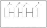
图1为称重系统示意图;Fig. 1 is the schematic diagram of weighing system;
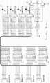
图2为控制单元内部示意图;Figure 2 is a schematic diagram of the interior of the control unit;
图3为控制单元电路示意图;Fig. 3 is a schematic diagram of the circuit of the control unit;
图中:1—称重传感器,2—控制单元,3—称重接线盒,4—称重主机,21—传感器信号输入,22—信号通道切换控制电路,23—拨码开关,24—传感器信号输出。In the figure: 1—Load sensor, 2—Control unit, 3—Weighing junction box, 4—Weighing host, 21—Sensor signal input, 22—Signal channel switching control circuit, 23—Dip switch, 24—Sensor signal output.
具体实施方式:detailed description:
为了加深对本发明的理解,下面结合附图对本实施例做详细的说明。In order to deepen the understanding of the present invention, the present embodiment will be described in detail below in conjunction with the accompanying drawings.
实施例1:参见图1,一种快速判断模拟量传感器称重系统故障的方法,所述方法包括以下步骤:Embodiment 1: Referring to Fig. 1, a method for quickly judging the failure of an analog sensor weighing system, the method includes the following steps:
步骤1:在传感器和接线盒中间串入控制单元;Step 1: Connect the control unit in series between the sensor and the junction box;
步骤2:传感器信号接入控制单元输入端子,控制单元输出端子接入接线盒。Step 2: The sensor signal is connected to the input terminal of the control unit, and the output terminal of the control unit is connected to the junction box.
其中,所述控制单元对每个传感器都设有拨码开关,当拨码开关选择到OFF档时,传感器所有信号都被断开(相当于传感器没有接入称重系统),当拨码开关选择到ON档时,传感器接入称重系统,控制单元还设有通道选择拨码开关,当拨码开关选择到OFF档时,控制单元一号输入通道的输入传感器从控制单元一号输出通道的输出,控制单元二号输入通道的输入传感器从控制单元二号输出通道的输出,控制单元三号输入通道的输入传感器从控制单元三号输出通道的输出,控制单元四号输入通道的输入传感器从控制单元四号输出通道的输出。当拨码开关选择到ON档时,控制单元一号输入通道的输入传感器从控制单元四号输出通道的输出,控制单元二号输入通道的输入传感器从控制单元三号输出通道的输出,控制单元三号输入通道的输入传感器从控制单元二号输出通道的输出,控制单元四号输入通道的输入传感器从控制单元一号输出通道的输出。实现接线盒通道互换的目的Wherein, the control unit is provided with a dial switch for each sensor. When the dial switch is selected to be OFF, all signals of the sensor are disconnected (equivalent to the sensor not connected to the weighing system), when the dial switch When the ON position is selected, the sensor is connected to the weighing system. The control unit is also equipped with a channel selection dial switch. When the dial switch is selected to the OFF position, the input sensor of the control unit No. 1 input channel is connected to the control unit No. 1 output channel. The output of the input sensor of the second input channel of the control unit is output from the second output channel of the control unit, the input sensor of the third input channel of the control unit is output from the third output channel of the control unit, and the input sensor of the fourth input channel of the control unit Output from output channel No. 4 of the control unit. When the DIP switch is selected to the ON position, the input sensor of the control unit’s No. 1 input channel outputs from the control unit’s No. 4 output channel, and the input sensor of the control unit’s No. 2 input channel outputs from the control unit’s No. 3 output channel. The input sensor of the No. 3 input channel is output from the No. 2 output channel of the control unit, and the input sensor of the No. 4 input channel of the control unit is output from the No. 1 output channel of the control unit. To achieve the purpose of junction box channel interchange
其中,控制单元主要由信号输入电路、信号输出电路及控制电路组成,该单元接入4路称重传感器信号,同时输出4路称重传感器信号,通过其上面的拨码开关实现不同的功能,拨码开关分为传感器拨码开关和通道选择拨码开关,主要有以下几个功能:Among them, the control unit is mainly composed of signal input circuit, signal output circuit and control circuit. The unit is connected to 4 load cell signals and
A、切断传感器信号,共有4组,当任意一组打在ON侧,传感器信号正常输入、输出。当打在OFF侧,对应输出通道传感器信号禁止输入称重接线盒,相当于该传感器被取消;A. Cut off the sensor signal. There are 4 groups in total. When any group is on the ON side, the sensor signal is input and output normally. When it is on the OFF side, the sensor signal of the corresponding output channel is prohibited from entering the weighing junction box, which is equivalent to the cancellation of the sensor;
B、通道选择功能,通过通道选择拨码开关实现,B. The channel selection function is realized through the channel selection DIP switch.
当打在OFF侧时,输入通道一的传感器信号从输出通道一输出,输入通道二的传感器信号从输出通道二输出,输入通道三的传感器信号从输出通道三输出,输入通道四的传感器信号从输出通道四输出。When it is on the OFF side, the sensor signal of
当打在ON侧时,输入通道一的传感器信号从输出通道四输出,输入通道二的传感器信号从输出通道三输出,输入通道三的传感器信号从输出通道二输出,输入通道四的传感器信号从输出通道一输出。When it is on the ON side, the sensor signal of
具体判断方法如下:The specific judgment method is as follows:
1)在称重传感器1和称重接线盒的中间接入控制单元2,即称重传感器接控制单元2的输入接口,控制单元2的输出接口接入接线盒的输入接口,通道选择拨码开关打在OFF档,传感器选择拨码开关全部打在ON档;1) Connect the
2)称重系统同一侧的2个传感器分别接专用控制单元的一,二通道(或三,四通道);2) The two sensors on the same side of the weighing system are respectively connected to the first and second channels (or third and fourth channels) of the dedicated control unit;
3)称重系统故障时,首先将所有传感器选择拨码开关全部打在OFF档,每次将1个传感器选择拨码开关打在ON档,观察称重数据,如果有数据并且稳定,则证明该路传感器正常。否则,证明该路传感器异常,将该传感器选择拨码开关打在OFF档;3) When the weighing system fails, first turn all the sensor selection DIP switches to the OFF position, each time turn one sensor selection DIP switch to the ON position, and observe the weighing data. If there is data and it is stable, it proves This road sensor is normal. Otherwise, it proves that the sensor of this road is abnormal, and the sensor selection DIP switch is set to OFF position;
4)将故障传感器选择拨码开关打在OFF档后,观察称重数据,同样的工况下,数据应该基本稳定且相差不大,如果发现有较大差异,则将故障传感器同侧的传感器选择拨码开关也打在OFF档。可临时维持称重系统使用;4) Turn the faulty sensor selection dial switch to the OFF position, and observe the weighing data. Under the same working conditions, the data should be basically stable with little difference. If there is a large difference, replace the sensor on the same side as the faulty sensor. The selection DIP switch is also in the OFF position. The weighing system can be maintained temporarily;
5)为判断故障传感器的详细故障,将正常的一侧的2个传感器选择拨码开关打在OFF档。将非正常的一侧的两个传感器选择拨码开关打在ON档。将通道选择拨码开关打在ON档,如果称重系统恢复正常,则证明接线盒有问题,如果仍然异常,则证明故障在传感器处;5) In order to judge the detailed fault of the faulty sensor, set the two sensor selection dial switches on the normal side to the OFF position. Turn the two sensor selection DIP switches on the abnormal side to the ON position. Turn the channel selection DIP switch to the ON position. If the weighing system returns to normal, it proves that there is a problem with the junction box. If it is still abnormal, it proves that the fault is at the sensor;
6)在第3步测试中,如果任意一个传感器都无法使得称重系统恢复正常,则证明系统故障出在称重系统总线上,需要更换总线。6) In the third step of the test, if any sensor cannot restore the weighing system to normal, it proves that the system failure is on the weighing system bus, and the bus needs to be replaced.
需要说明的是上述实施例,并非用来限定本发明的保护范围,在上述技术方案的基础上所作出的等同变换或替代均落入本发明权利要求所保护的范围。It should be noted that the above-mentioned embodiments are not used to limit the protection scope of the present invention, and equivalent transformations or substitutions made on the basis of the above-mentioned technical solutions all fall within the protection scope of the claims of the present invention.
Claims (4)
Translated fromChinesePriority Applications (1)
| Application Number | Priority Date | Filing Date | Title |
|---|---|---|---|
| CN202110682095.XACN115493682A (en) | 2021-06-19 | 2021-06-19 | Method for rapidly judging faults of analog quantity sensor weighing system |
Applications Claiming Priority (1)
| Application Number | Priority Date | Filing Date | Title |
|---|---|---|---|
| CN202110682095.XACN115493682A (en) | 2021-06-19 | 2021-06-19 | Method for rapidly judging faults of analog quantity sensor weighing system |
Publications (1)
| Publication Number | Publication Date |
|---|---|
| CN115493682Atrue CN115493682A (en) | 2022-12-20 |
Family
ID=84464648
Family Applications (1)
| Application Number | Title | Priority Date | Filing Date |
|---|---|---|---|
| CN202110682095.XAPendingCN115493682A (en) | 2021-06-19 | 2021-06-19 | Method for rapidly judging faults of analog quantity sensor weighing system |
Country Status (1)
| Country | Link |
|---|---|
| CN (1) | CN115493682A (en) |
Citations (11)
| Publication number | Priority date | Publication date | Assignee | Title |
|---|---|---|---|---|
| US5296655A (en)* | 1992-02-10 | 1994-03-22 | Beowulf Corporation | Control system for multiple input scales |
| CN102564558A (en)* | 2012-01-19 | 2012-07-11 | 徐工集团工程机械股份有限公司科技分公司 | Asphalt mixing station and multi-point electronic scale fault detecting device and detecting method for asphalt mixing station |
| CN102621433A (en)* | 2012-04-18 | 2012-08-01 | 潍柴动力股份有限公司 | Failure detection equipment for sensors of internal combustion engine |
| CN203587214U (en)* | 2013-11-18 | 2014-05-07 | 重庆大唐测控技术有限公司 | Remote fault detecting and positioning device for automobile scale analog weighing sensor |
| CN104062530A (en)* | 2014-07-11 | 2014-09-24 | 湖南长城信息金融设备有限责任公司 | Mobile terminal hardware fault detecting device and method |
| CN105094025A (en)* | 2014-04-30 | 2015-11-25 | 台达电子企业管理(上海)有限公司 | Transmitter and monitoring system thereof |
| CN206557315U (en)* | 2017-03-21 | 2017-10-13 | 北京润科通用技术有限公司 | A kind of signal access device for direct fault location, direct fault location test system |
| CN107421618A (en)* | 2017-05-17 | 2017-12-01 | 江西众加利高科技股份有限公司 | A kind of device for detecting failure respectively to complete-vehicle-type weighing sensor |
| CN107491004A (en)* | 2017-08-09 | 2017-12-19 | 北京特种机械研究所 | Intelligent weighing tester and its application method |
| CN207731111U (en)* | 2017-12-19 | 2018-08-14 | 广州卓振智能科技有限公司 | A kind of input/output unit of analogue quantity switch amount monitoring |
| CN111351560A (en)* | 2020-03-27 | 2020-06-30 | 江苏联峰实业有限公司 | A load cell online detection device |
- 2021
- 2021-06-19CNCN202110682095.XApatent/CN115493682A/enactivePending
Patent Citations (11)
| Publication number | Priority date | Publication date | Assignee | Title |
|---|---|---|---|---|
| US5296655A (en)* | 1992-02-10 | 1994-03-22 | Beowulf Corporation | Control system for multiple input scales |
| CN102564558A (en)* | 2012-01-19 | 2012-07-11 | 徐工集团工程机械股份有限公司科技分公司 | Asphalt mixing station and multi-point electronic scale fault detecting device and detecting method for asphalt mixing station |
| CN102621433A (en)* | 2012-04-18 | 2012-08-01 | 潍柴动力股份有限公司 | Failure detection equipment for sensors of internal combustion engine |
| CN203587214U (en)* | 2013-11-18 | 2014-05-07 | 重庆大唐测控技术有限公司 | Remote fault detecting and positioning device for automobile scale analog weighing sensor |
| CN105094025A (en)* | 2014-04-30 | 2015-11-25 | 台达电子企业管理(上海)有限公司 | Transmitter and monitoring system thereof |
| CN104062530A (en)* | 2014-07-11 | 2014-09-24 | 湖南长城信息金融设备有限责任公司 | Mobile terminal hardware fault detecting device and method |
| CN206557315U (en)* | 2017-03-21 | 2017-10-13 | 北京润科通用技术有限公司 | A kind of signal access device for direct fault location, direct fault location test system |
| CN107421618A (en)* | 2017-05-17 | 2017-12-01 | 江西众加利高科技股份有限公司 | A kind of device for detecting failure respectively to complete-vehicle-type weighing sensor |
| CN107491004A (en)* | 2017-08-09 | 2017-12-19 | 北京特种机械研究所 | Intelligent weighing tester and its application method |
| CN207731111U (en)* | 2017-12-19 | 2018-08-14 | 广州卓振智能科技有限公司 | A kind of input/output unit of analogue quantity switch amount monitoring |
| CN111351560A (en)* | 2020-03-27 | 2020-06-30 | 江苏联峰实业有限公司 | A load cell online detection device |
Similar Documents
| Publication | Publication Date | Title |
|---|---|---|
| CN101738568B (en) | Distributed DC ground fault detection device | |
| CN102699033B (en) | Rolling mill SONY magneto-scale online redundancy method | |
| CN204538802U (en) | Middle pressure power transmission and distribution automatic switching control system | |
| CN115493682A (en) | Method for rapidly judging faults of analog quantity sensor weighing system | |
| CN106774026B (en) | Intelligent line controller | |
| JP3054459B2 (en) | A device that generates a current corresponding to the amount supplied | |
| CN102298103A (en) | Direct-current power distribution intelligent detection unit | |
| CN102826384A (en) | Liquid crystal display panel conveying system and automatic crane thereof | |
| CN117895357A (en) | Nuclear power plant distribution board parallel maintenance method and system | |
| KR20140057720A (en) | System of protective control for substation facilities | |
| CN108471164B (en) | Intelligent detection and alarm method and device for pressing plate of transformer protection device | |
| CN114784764B (en) | Arc protection system and method | |
| CN206323308U (en) | A kind of new one drag two parallel resonance power inverter control unit | |
| CN212622904U (en) | Novel main circuit insulation detection device | |
| JP3684292B2 (en) | Power system controller | |
| CN220961711U (en) | High-voltage equipment fault first-out judging device | |
| CN216086166U (en) | A distributed control high voltage reactive power automatic compensation system | |
| JPH04168506A (en) | Equipment monitoring diagnostic system | |
| CN217955694U (en) | Point single-double-purpose alarm limit switch | |
| CN104089731A (en) | Electric head torque checking device | |
| JPH03215114A (en) | Protective relay device with inspection function | |
| CN207457413U (en) | T-shaped transmission line malfunction indicates system | |
| JP2012055138A (en) | Equipment integration system for substation | |
| JP2011229257A (en) | Inspection apparatus for protective relay | |
| JP2016220273A (en) | Protection relay operation test system |
Legal Events
| Date | Code | Title | Description |
|---|---|---|---|
| PB01 | Publication | ||
| PB01 | Publication | ||
| SE01 | Entry into force of request for substantive examination | ||
| SE01 | Entry into force of request for substantive examination |