CN115493598A - Target positioning method and device in motion process and storage medium - Google Patents
Target positioning method and device in motion process and storage mediumDownload PDFInfo
- Publication number
- CN115493598A CN115493598ACN202211423264.9ACN202211423264ACN115493598ACN 115493598 ACN115493598 ACN 115493598ACN 202211423264 ACN202211423264 ACN 202211423264ACN 115493598 ACN115493598 ACN 115493598A
- Authority
- CN
- China
- Prior art keywords
- target
- preset
- measurement
- coordinates
- distance
- Prior art date
- Legal status (The legal status is an assumption and is not a legal conclusion. Google has not performed a legal analysis and makes no representation as to the accuracy of the status listed.)
- Granted
Links
Images


Classifications
- G—PHYSICS
- G01—MEASURING; TESTING
- G01C—MEASURING DISTANCES, LEVELS OR BEARINGS; SURVEYING; NAVIGATION; GYROSCOPIC INSTRUMENTS; PHOTOGRAMMETRY OR VIDEOGRAMMETRY
- G01C21/00—Navigation; Navigational instruments not provided for in groups G01C1/00 - G01C19/00
- G01C21/20—Instruments for performing navigational calculations
- G—PHYSICS
- G01—MEASURING; TESTING
- G01S—RADIO DIRECTION-FINDING; RADIO NAVIGATION; DETERMINING DISTANCE OR VELOCITY BY USE OF RADIO WAVES; LOCATING OR PRESENCE-DETECTING BY USE OF THE REFLECTION OR RERADIATION OF RADIO WAVES; ANALOGOUS ARRANGEMENTS USING OTHER WAVES
- G01S19/00—Satellite radio beacon positioning systems; Determining position, velocity or attitude using signals transmitted by such systems
- G01S19/38—Determining a navigation solution using signals transmitted by a satellite radio beacon positioning system
- G01S19/39—Determining a navigation solution using signals transmitted by a satellite radio beacon positioning system the satellite radio beacon positioning system transmitting time-stamped messages, e.g. GPS [Global Positioning System], GLONASS [Global Orbiting Navigation Satellite System] or GALILEO
- G01S19/42—Determining position
- G01S19/43—Determining position using carrier phase measurements, e.g. kinematic positioning; using long or short baseline interferometry
- G—PHYSICS
- G06—COMPUTING OR CALCULATING; COUNTING
- G06T—IMAGE DATA PROCESSING OR GENERATION, IN GENERAL
- G06T7/00—Image analysis
- G06T7/60—Analysis of geometric attributes
- G06T7/66—Analysis of geometric attributes of image moments or centre of gravity
- G—PHYSICS
- G06—COMPUTING OR CALCULATING; COUNTING
- G06T—IMAGE DATA PROCESSING OR GENERATION, IN GENERAL
- G06T7/00—Image analysis
- G06T7/70—Determining position or orientation of objects or cameras
- G06T7/73—Determining position or orientation of objects or cameras using feature-based methods
- G—PHYSICS
- G06—COMPUTING OR CALCULATING; COUNTING
- G06T—IMAGE DATA PROCESSING OR GENERATION, IN GENERAL
- G06T2207/00—Indexing scheme for image analysis or image enhancement
- G06T2207/10—Image acquisition modality
- G06T2207/10016—Video; Image sequence
Landscapes
- Engineering & Computer Science (AREA)
- Radar, Positioning & Navigation (AREA)
- Remote Sensing (AREA)
- Physics & Mathematics (AREA)
- General Physics & Mathematics (AREA)
- Computer Vision & Pattern Recognition (AREA)
- Theoretical Computer Science (AREA)
- Geometry (AREA)
- Computer Networks & Wireless Communication (AREA)
- Automation & Control Theory (AREA)
- Length Measuring Devices By Optical Means (AREA)
Abstract
Description
Translated fromChinese技术领域technical field
本申请涉及目标定位技术领域,尤其涉及一种运动过程中的目标定位方法、装置及存储介质。The present application relates to the technical field of target positioning, and in particular to a target positioning method, device and storage medium during motion.
背景技术Background technique
光电吊舱是吊挂在机身或机翼下的流线形短舱段,其内部通常搭载有高清可见光相机、红外热像仪、激光测距机、光电跟踪器等光电探测设备,能够实现对目标识别、定位、跟踪及动态监视等功能。随着无人机技术的飞速发展,光电吊舱在资源探测、灾害搜救、目标监控、目标查找等方面发挥了越来越重要的作用。The photoelectric pod is a streamlined nacelle section suspended under the fuselage or wing. It is usually equipped with photoelectric detection equipment such as high-definition visible light cameras, infrared thermal imaging cameras, laser range finders, photoelectric trackers, etc. Target recognition, positioning, tracking and dynamic monitoring and other functions. With the rapid development of UAV technology, photoelectric pods have played an increasingly important role in resource detection, disaster search and rescue, target monitoring, and target finding.
目前,光电吊舱通常采用有源定位方法来对目标进行定位。有源定位方法是采用激光对目标进行测距,然后根据无人机姿态和光电姿态对目标位置进行解算的方法。At present, photoelectric pods usually use active positioning methods to locate targets. The active positioning method is to use laser to measure the distance of the target, and then calculate the target position according to the UAV attitude and photoelectric attitude.
但是,目前的有源定位方法严重依赖光电测角精度、光电平台稳定性、无人机姿态测量精度、无人机飞行稳定性等,普通无人机和光电吊舱在定位时具有较大的误差,不能满足应用场景对定位精度的要求。However, the current active positioning methods rely heavily on the accuracy of photoelectric angle measurement, the stability of photoelectric platforms, the accuracy of UAV attitude measurement, and the stability of UAV flight. Ordinary UAVs and photoelectric pods have a large The error cannot meet the positioning accuracy requirements of the application scenario.
发明内容Contents of the invention
本申请实施例通过提供一种运动过程中的目标定位方法、装置及存储介质,解决了现有技术中普通无人机和光电装置在定位时具有较大误差的技术问题。The embodiments of the present application provide a method, device and storage medium for target positioning during movement, which solves the technical problem of relatively large errors in positioning of ordinary drones and photoelectric devices in the prior art.
第一方面,本申请实施例提供了一种运动过程中的目标定位方法,所述方法包括:沿预设规划路径对每个目标进行有源定位,获得每个所述目标的初始坐标,并基于所述目标的初始坐标获得预设测量路径;在所述预设测量路径上,基于各所述目标的初始坐标搜索并锁定需定位的目标;沿所述预设测量路径运动过程中,采集每个所述目标的大于预设组数的测量数据;其中,所述测量数据包括测量点的位置信息,以及所述测量点至所述目标的测量距离;针对每个所述目标,多次不完全重复地选取预设组数的所述测量数据,并判断基于选取的预设组数的所述测量数据是否能确定目标的坐标;若能,则将所确定的目标的坐标作为目标的精确坐标;否则,以预设距离误差对每个所述目标的初始坐标进行拟合,确定每个所述目标的精确坐标。In the first aspect, the embodiment of the present application provides a target positioning method during motion, the method comprising: performing active positioning on each target along a preset planned path, obtaining the initial coordinates of each target, and Obtain a preset measurement path based on the initial coordinates of the target; on the preset measurement path, search and lock the target to be positioned based on the initial coordinates of each of the targets; during movement along the preset measurement path, collect Measurement data greater than the preset number of groups for each of the targets; wherein, the measurement data includes position information of the measurement point, and the measurement distance from the measurement point to the target; for each of the targets, multiple times Selecting the measurement data of the preset number of groups without complete repetition, and judging whether the coordinates of the target can be determined based on the measurement data of the selected preset number of groups; if so, using the determined coordinates of the target as the target precise coordinates; otherwise, the initial coordinates of each of the targets are fitted with a preset distance error to determine the precise coordinates of each of the targets.
结合第一方面,在一种可能的实现方式中,所述以预设距离误差对每个所述目标的所述初始坐标进行拟合,确定每个所述目标的精确坐标,包括:以每个所述目标的所述初始坐标为拟合中心点,执行拟合步骤;判断所述拟合步骤中的预设间隔距离是否达到所述预设距离误差;若未达到,调小所述预设间隔距离,并将误差矩阵中最小值所对应的坐标作为所述拟合中心点,循环执行所述拟合步骤;若达到,将所述误差矩阵中最小值所对应的坐标作为所述精确坐标;其中,所述拟合步骤包括:以所述预设间隔距离将所述拟合中心点在平面的两个垂直方向上分别扩展第一预设次数,获得矩阵平面;以所述预设间隔距离将所述矩阵平面向上下分别扩展第二预设次数,获得拟合坐标矩阵;确定所述拟合坐标矩阵中的每个坐标与多个所述测量点之间的计算距离;求解每个所述计算距离与对应所述测量距离的误差,并确定所述拟合坐标矩阵中的每个坐标的多个误差的绝对值之和,获得所述误差矩阵;确定所述误差矩阵中最小值所对应的坐标。With reference to the first aspect, in a possible implementation manner, the fitting the initial coordinates of each of the targets with a preset distance error, and determining the precise coordinates of each of the targets includes: The initial coordinates of each of the targets are the fitting center point, and a fitting step is performed; it is judged whether the preset interval distance in the fitting step reaches the preset distance error; if it is not reached, the preset distance is adjusted down. Set the interval distance, and use the coordinates corresponding to the minimum value in the error matrix as the fitting center point, and execute the fitting step in a loop; if it is reached, use the coordinates corresponding to the minimum value in the error matrix as the accurate Coordinates; wherein, the fitting step includes: expanding the fitting center point in the two vertical directions of the plane by a first preset number of times with the preset interval distance to obtain a matrix plane; with the preset Extend the matrix plane up and down for a second preset number of times to obtain a fitted coordinate matrix; determine the calculated distance between each coordinate in the fitted coordinate matrix and a plurality of the measurement points; solve each The calculated distance and the error corresponding to the measured distance, and determine the sum of the absolute values of the multiple errors of each coordinate in the fitted coordinate matrix to obtain the error matrix; determine the minimum error matrix in the error matrix The coordinates to which the value corresponds.
结合第一方面,在一种可能的实现方式中,每个所述目标对应的多个所述测量点满足如下条件:每个所述目标的任意一个所述测量点与其他任意两个所述测量点组合形成的角度大于预设角度;在每个所述目标的任意三个所述测量点组成的三角形中,任意顶点到对边的距离大于或等于预设距离。With reference to the first aspect, in a possible implementation manner, the multiple measurement points corresponding to each target meet the following conditions: any one of the measurement points of each target is different from any other two of the measurement points The angle formed by the combination of the measurement points is greater than the preset angle; in the triangle formed by any three of the measurement points of each target, the distance from any vertex to the opposite side is greater than or equal to the preset distance.
结合第一方面,在一种可能的实现方式中,所述基于所述目标的初始坐标获得预设测量路径,包括:以所述目标的所述初始坐标为圆心并以所述预设规划路径为切线,获得最佳视角点;以预设缓冲半径为每个所述最佳视角点建立缓冲范围;对所述缓冲范围的多条切线进行并集运算,获得缓冲多边形;沿所述缓冲多边形的中心分割线,每隔预设长度设置一段圆弧,并使相邻两个所述圆弧位于所述中心分割线的两侧;组合多段所述圆弧,形成所述预设测量路径。With reference to the first aspect, in a possible implementation manner, the obtaining a preset measurement path based on the initial coordinates of the target includes: taking the initial coordinates of the target as a center and taking the preset planning path Obtain the best view point for the tangent; establish a buffer range for each of the best view points with a preset buffer radius; perform a union operation on multiple tangents in the buffer range to obtain a buffer polygon; The central dividing line, set a section of circular arc every preset length, and make two adjacent circular arcs located on both sides of the central dividing line; combine multiple sections of the circular arc to form the preset measurement path.
结合第一方面,在一种可能的实现方式中,所述采集每个所述目标的大于预设组数的测量数据,包括:将每两段相邻的所述圆弧按照预设比例划分为开始段、中间段和末尾段;对每个所述目标在所述开始段和所述末尾段至少各采集一个所述测量数据,在所述中间段至少采集两个所述测量数据。With reference to the first aspect, in a possible implementation manner, the collecting the measurement data of each target greater than the preset number of groups includes: dividing every two adjacent arcs according to a preset ratio into initial segment, middle segment and end segment; for each target, at least one measurement data is collected in the start segment and the end segment, and at least two measurement data are collected in the middle segment.
结合第一方面,在一种可能的实现方式中,所述在所述预设测量路径上,基于各所述目标的初始坐标搜索并锁定需定位的目标,包括:根据所述初始坐标和用于定位所述目标的光电装置所处位置,确定所述目标所在方位;控制所述光电装置旋转至所述目标所在方位;在所述光电装置的视场中进行搜索;搜索到所述目标后将所述光电装置的焦点移动至所述目标的中心。With reference to the first aspect, in a possible implementation manner, searching and locking the target to be positioned based on the initial coordinates of each target on the preset measurement path includes: Determine the azimuth of the target based on the location of the photoelectric device for locating the target; control the photoelectric device to rotate to the azimuth of the target; search in the field of view of the photoelectric device; after searching for the target Moving the focus of the optoelectronic device to the center of the target.
结合第一方面,在一种可能的实现方式中,所述方法还包括:在所述有源定位过程中采集所述目标的图像特征,形成目标特征库;所述在所述光电装置的视场中进行搜索,包括:利用所述目标特征库,在所述光电装置的视场中进行特征匹配。With reference to the first aspect, in a possible implementation manner, the method further includes: collecting image features of the target during the active positioning process to form a target feature library; Searching in the field includes: using the target feature library to perform feature matching in the field of view of the optoelectronic device.
结合第一方面,在一种可能的实现方式中,所述在所述预设测量路径上,基于各所述目标的初始坐标搜索并锁定需定位的目标,还包括:调整所述光电装置的视场尺寸至所述有源定位时的视场尺寸;查找误差分布表,以当前距离的误差范围的预设倍数在所述光电装置的视场中搜索所述目标。With reference to the first aspect, in a possible implementation manner, the searching and locking the target to be positioned based on the initial coordinates of each target on the preset measurement path further includes: adjusting the photoelectric device The size of the field of view is the size of the field of view of the active positioning; look up the error distribution table, and search for the target in the field of view of the photoelectric device with a preset multiple of the error range of the current distance.
第二方面,本申请实施例提供了一种运动过程中的目标定位装置,所述装置包括:路径模块,用于沿预设规划路径对每个所述目标进行有源定位,获得每个所述目标的初始坐标,并基于所述目标的初始坐标获得预设测量路径;锁定模块,用于在所述预设测量路径上,基于各所述目标的初始坐标搜索并锁定需定位的目标;采集模块,用于沿所述预设测量路径运动过程中,采集每个所述目标的大于预设组数的测量数据;其中,所述测量数据包括测量点的位置信息,以及所述测量点至所述目标的测量距离;计算模块,用于针对每个所述目标,多次不完全重复地选取预设组数的所述测量数据,并判断基于选取的预设组数的所述测量数据是否能确定目标的坐标;若能,则将所确定的目标的坐标作为目标的精确坐标;否则,以预设距离误差对每个所述目标的初始坐标进行拟合,确定每个所述目标的精确坐标。In the second aspect, the embodiment of the present application provides a device for locating objects during movement, the device comprising: a path module, configured to actively locate each of the objects along a preset planned path, and obtain each of the objects The initial coordinates of the target, and obtain a preset measurement path based on the initial coordinates of the target; the locking module is used to search and lock the target to be positioned on the preset measurement path based on the initial coordinates of each of the targets; A collection module, configured to collect measurement data of each target greater than a preset number of groups during movement along the preset measurement path; wherein, the measurement data includes position information of measurement points, and the measurement points The measurement distance to the target; the calculation module is used to select the measurement data of the preset number of groups repeatedly and incompletely repeatedly for each of the targets, and determine the measurement based on the selected preset number of groups Whether the data can determine the coordinates of the target; if yes, the determined coordinates of the target are used as the precise coordinates of the target; otherwise, the initial coordinates of each target are fitted with a preset distance error to determine each The exact coordinates of the target.
结合第二方面,在一种可能的实现方式中,所述计算模块在用于以预设距离误差对每个所述目标的所述初始坐标进行拟合,确定每个所述目标的精确坐标时,具体用于:以每个所述目标的所述初始坐标为拟合中心点,执行拟合步骤;判断所述拟合步骤中的预设间隔距离是否达到所述预设距离误差;若未达到,调小所述预设间隔距离,并将误差矩阵中最小值所对应的坐标作为所述拟合中心点,循环执行所述拟合步骤;若达到,将所述误差矩阵中最小值所对应的坐标作为所述精确坐标;其中,所述拟合步骤包括:以所述预设间隔距离将所述拟合中心点在平面的两个垂直方向上分别扩展第一预设次数,获得矩阵平面;以所述预设间隔距离将所述矩阵平面向上下分别扩展第二预设次数,获得拟合坐标矩阵;确定所述拟合坐标矩阵中的每个坐标与多个所述测量点之间的计算距离;求解每个所述计算距离与对应所述测量距离的误差,并确定所述拟合坐标矩阵中的每个坐标的多个误差的绝对值之和,获得所述误差矩阵;确定所述误差矩阵中最小值所对应的坐标。With reference to the second aspect, in a possible implementation manner, the calculation module is used to fit the initial coordinates of each of the targets with a preset distance error, and determine the precise coordinates of each of the targets When, it is specifically used for: using the initial coordinates of each of the targets as the fitting center point, performing the fitting step; judging whether the preset interval distance in the fitting step reaches the preset distance error; if If it is not reached, reduce the preset interval distance, and use the coordinates corresponding to the minimum value in the error matrix as the fitting center point, and execute the fitting step in a loop; if reached, set the minimum value in the error matrix to The corresponding coordinates are used as the precise coordinates; wherein, the fitting step includes: extending the fitting center point in two vertical directions of the plane by a first preset number of times respectively at the preset interval distance to obtain Matrix plane; expand the matrix plane up and down for a second preset number of times with the preset interval distance to obtain a fitting coordinate matrix; determine each coordinate in the fitting coordinate matrix and a plurality of the measuring points Calculate the distance between; solve the error between each of the calculated distance and the corresponding measured distance, and determine the sum of the absolute values of the multiple errors of each coordinate in the fitted coordinate matrix to obtain the error matrix ; Determine the coordinates corresponding to the minimum value in the error matrix.
结合第二方面,在一种可能的实现方式中,每个所述目标对应的多个所述测量点满足如下条件:每个所述目标的任意一个所述测量点与其他任意两个所述测量点组合形成的角度大于预设角度;在每个所述目标的任意三个所述测量点组成的三角形中,任意顶点到对边的距离大于或等于预设距离。With reference to the second aspect, in a possible implementation manner, the multiple measurement points corresponding to each of the targets meet the following conditions: any one of the measurement points of each of the targets is different from any other two of the measurement points The angle formed by the combination of the measurement points is greater than the preset angle; in the triangle formed by any three of the measurement points of each target, the distance from any vertex to the opposite side is greater than or equal to the preset distance.
结合第二方面,在一种可能的实现方式中,所述路径模块用于基于所述目标的初始坐标获得预设测量路径时,具体用于:以所述目标的所述初始坐标为圆心并以所述预设规划路径为切线,获得最佳视角点;以预设缓冲半径为每个所述最佳视角点建立缓冲范围;对所述缓冲范围的多条切线进行并集运算,获得缓冲多边形;沿所述缓冲多边形的中心分割线,每隔预设长度设置一段圆弧,并使相邻两个所述圆弧位于所述中心分割线的两侧;组合多段所述圆弧,形成所述预设测量路径。With reference to the second aspect, in a possible implementation manner, when the path module is used to obtain a preset measurement path based on the initial coordinates of the target, it is specifically configured to: take the initial coordinates of the target as the center of a circle and Taking the preset planning path as a tangent to obtain the best view point; using the preset buffer radius to establish a buffer range for each of the best view points; performing a union operation on multiple tangents of the buffer range to obtain a buffer Polygon; along the central dividing line of the buffer polygon, a section of circular arc is set every preset length, and two adjacent circular arcs are located on both sides of the central dividing line; multiple sections of the circular arc are combined to form The preset measurement path.
结合第二方面,在一种可能的实现方式中,所述采集模块具体用于:将每两段相邻的所述圆弧按照预设比例划分为开始段、中间段和末尾段;对每个所述目标在所述开始段和所述末尾段至少各采集一个所述测量数据,在所述中间段至少采集两个所述测量数据。With reference to the second aspect, in a possible implementation manner, the acquisition module is specifically configured to: divide every two adjacent arcs into a start segment, a middle segment, and an end segment according to a preset ratio; The target collects at least one piece of measurement data in the beginning section and the end section, and collects at least two pieces of measurement data in the middle section.
结合第二方面,在一种可能的实现方式中,所述锁定模块具体用于:根据所述初始坐标和用于定位所述目标的光电装置所处位置,确定所述目标所在方位;控制所述光电装置旋转至所述目标所在方位;在所述光电装置的视场中进行搜索;搜索到所述目标后将所述光电装置的焦点移动至所述目标的中心。With reference to the second aspect, in a possible implementation manner, the locking module is specifically configured to: determine the orientation of the target according to the initial coordinates and the position of the photoelectric device used to locate the target; The photoelectric device rotates to the position of the target; searches in the field of view of the photoelectric device; and moves the focus of the photoelectric device to the center of the target after the target is found.
结合第二方面,在一种可能的实现方式中,所述装置还包括:特征模块,用于在所述有源定位过程中采集所述目标的图像特征,形成目标特征库;所述锁定模块在所述光电装置的视场中进行搜索时,具体用于:利用所述目标特征库,在所述光电装置的视场中进行特征匹配。With reference to the second aspect, in a possible implementation manner, the device further includes: a feature module, configured to collect image features of the target during the active positioning process to form a target feature library; the locking module When searching in the field of view of the optoelectronic device, it is specifically used to: use the target feature library to perform feature matching in the field of view of the optoelectronic device.
结合第二方面,在一种可能的实现方式中,所述锁定模块还用于:调整所述光电装置的视场尺寸至所述有源定位时的视场尺寸;查找误差分布表,以当前距离的误差范围的预设倍数在所述光电装置的视场中搜索所述目标。With reference to the second aspect, in a possible implementation manner, the locking module is further configured to: adjust the size of the field of view of the photoelectric device to the size of the field of view when the active is positioned; look up an error distribution table, and use the current A preset multiple of an error range of distance searches for the target in the field of view of the optoelectronic device.
第三方面,本申请实施例提供了一种计算机可读存储介质,所述计算机可读存储介质存储有计算机可读指令,所述计算机可读指令被处理器执行时实现第一方面或第一方面任一种可能实现方式所述的方法。In a third aspect, an embodiment of the present application provides a computer-readable storage medium, the computer-readable storage medium stores computer-readable instructions, and when the computer-readable instructions are executed by a processor, the first aspect or the first The method described in any possible implementation manner of the aspect.
本申请实施例中提供的技术方案,至少具有如下技术效果或优点:The technical solutions provided in the embodiments of the present application have at least the following technical effects or advantages:
本申请实施例提供了一种运动过程中的目标定位方法,该方法通过多次不完全重复地选取预设组数的测量数据,或者对每个目标的初始坐标进行拟合来目标的精确坐标,大幅减小了定位误差,提高了对目标定位的精度。The embodiment of the present application provides a target positioning method in the process of movement. The method obtains the precise coordinates of the target by repeatedly selecting preset sets of measurement data incompletely and repeatedly, or fitting the initial coordinates of each target. , greatly reducing the positioning error and improving the accuracy of target positioning.
附图说明Description of drawings
为了更清楚地说明本申请实施例或现有技术中的技术方案,下面将对本申请实施例或现有技术描述中所需要使用的附图作简单地介绍,显而易见地,下面描述中的附图是本发明的一些实施例,对于本领域普通技术人员来讲,在不付出创造性劳动的前提下,还可以根据这些附图获得其他的附图。In order to more clearly illustrate the technical solutions in the embodiments of the application or the prior art, the following will briefly introduce the accompanying drawings that need to be used in the description of the embodiments of the application or the prior art. Obviously, the accompanying drawings in the following description These are some embodiments of the present invention. Those skilled in the art can also obtain other drawings based on these drawings without creative work.
图1为本申请实施例提供的光电装置进行目标定位的场景示意图;FIG. 1 is a schematic diagram of a scene where an optoelectronic device performs target positioning according to an embodiment of the present application;
图2为本申请实施例提供的运动过程中的目标定位方法的流程图;FIG. 2 is a flow chart of a method for locating a target during motion provided by an embodiment of the present application;
图3为本申请实施例提供的采集测量数据的示意图;Fig. 3 is the schematic diagram of the acquisition measurement data provided by the embodiment of the present application;
图4为本申请实施例提供的目标平差方法的计算示意图;Fig. 4 is the calculation schematic diagram of the target adjustment method provided by the embodiment of the present application;
图5A为本申请实施例提供的对目标的初始坐标进行拟合的流程图;FIG. 5A is a flow chart for fitting the initial coordinates of the target provided by the embodiment of the present application;
图5B为本申请实施例提供的拟合步骤的具体流程图;FIG. 5B is a specific flow chart of the fitting steps provided in the embodiment of the present application;
图5C为本申请实施例提供的矩阵平面的示意图;Figure 5C is a schematic diagram of the matrix plane provided by the embodiment of the present application;
图5D为本申请实施例提供的多个矩阵平面的排列示意图;Figure 5D is a schematic diagram of the arrangement of multiple matrix planes provided by the embodiment of the present application;
图6A-图6E为本申请实施例提供的生成预设测量路径的过程示意图;6A-6E are schematic diagrams of the process of generating a preset measurement path provided by the embodiment of the present application;
图7为本申请实施例提供的生成预设测量路径的流程图;FIG. 7 is a flow chart of generating a preset measurement path provided by an embodiment of the present application;
图8为本申请实施例提供的采集测量数据的流程图;FIG. 8 is a flow chart of collecting measurement data provided by an embodiment of the present application;
图9为本申请实施例提供的搜索并锁定需定位目标的流程图;FIG. 9 is a flow chart of searching and locking a target to be located according to an embodiment of the present application;
图10为本申请实施例提供的在光电装置的视场中搜索目标的流程图;FIG. 10 is a flow chart of searching for a target in the field of view of an optoelectronic device provided by an embodiment of the present application;
图11为本申请实施例提供的运动过程中的目标定位装置的结构示意图。FIG. 11 is a schematic structural diagram of a target positioning device during a movement provided by an embodiment of the present application.
具体实施方式detailed description
下面将结合本申请实施例中的附图,对本申请实施例中的技术方案进行清楚、完整地描述,显然,所描述的实施例是本发明的一部分实施例,而不是全部的实施例。基于本发明中的实施例,本领域普通技术人员在没有做出创造性劳动前提下所获得的所有其他实施例,都属于本发明保护的范围。The following will clearly and completely describe the technical solutions in the embodiments of the present application with reference to the drawings in the embodiments of the present application. Obviously, the described embodiments are part of the embodiments of the present invention, not all of them. Based on the embodiments of the present invention, all other embodiments obtained by persons of ordinary skill in the art without making creative efforts belong to the protection scope of the present invention.
本申请实施例提供了一种运动过程中的目标定位方法,适用于如图1所示的应用场景,在图1所示的场景中包括地面测控平台分系统和无人机飞行平台分系统。The embodiment of the present application provides a target positioning method during motion, which is applicable to the application scenario shown in FIG. 1 . The scenario shown in FIG. 1 includes a ground measurement and control platform subsystem and a UAV flight platform subsystem.
地面测控平台分系统包括:地面测控运输车、RTK(Real - Time Kinematic,实时动态)差分基站设备、地面链路设备、无人机地面站和光电装置地面站。The ground measurement and control platform subsystem includes: ground measurement and control transport vehicle, RTK (Real-Time Kinematic, real-time dynamic) differential base station equipment, ground link equipment, UAV ground station and optoelectronic device ground station.
地面测控运输车是用来装载无人机、集成地面操作设备和监控设备、人员工作、系统机动运输的主要工具。The ground measurement and control transport vehicle is the main tool used to load unmanned aerial vehicles, integrate ground operation equipment and monitoring equipment, personnel work, and system mobile transportation.
RTK差分基站设备装载在地面测控运输车的车顶上,用于接收卫星定位信号,通过地面链路设备给无人机上的GNESS机载导航设备发送RTK差分信息,通过差分计算使GNESS机载导航设备能够给无人机和光电装置提供厘米级精度的定位信息,保证测量作业时刻系统具有精确的位置姿态信息。The RTK differential base station equipment is loaded on the roof of the ground measurement and control transport vehicle to receive satellite positioning signals, send RTK differential information to the GNESS airborne navigation equipment on the UAV through the ground link equipment, and make the GNESS airborne navigation through differential calculation The equipment can provide centimeter-level precision positioning information for drones and photoelectric devices, ensuring that the system has accurate position and attitude information at the time of measurement operations.
地面链路设备装载在地面测控运输车的车顶上,与无人机上的机载链路设备进行无线电连接,提供无人机与地面设备的通信。链路上行传输信号具有:RTK差分信号、无人机控制数据、光电装置控制数据、遥控器控制数据、飞行测量管理任务指令。链路下行传输信号具有:无人机测控数据、光电装置测控数据、光电装置视频数据、发动机状态数据、飞行测量管理任务数据。The ground link equipment is loaded on the roof of the ground measurement and control transport vehicle, and is radio-connected with the airborne link equipment on the UAV to provide communication between the UAV and the ground equipment. Link uplink transmission signals include: RTK differential signal, UAV control data, photoelectric device control data, remote control control data, and flight measurement management task instructions. The downlink transmission signal of the link includes: UAV measurement and control data, photoelectric device measurement and control data, photoelectric device video data, engine status data, and flight measurement management task data.
无人机地面站安装在地面测控运输车里,是人工控制无人机的计算机设备,通过无人机地面站能够监控无人机飞行状态、监控无人机的设备运行状态、控制无人机的飞行任务。The UAV ground station is installed in the ground measurement and control transport vehicle. It is a computer device for artificially controlling the UAV. The UAV ground station can monitor the flight status of the UAV, monitor the equipment operation status of the UAV, and control the UAV. flight missions.
光电装置地面站安装在地面测控运输车里,是人工控制光电装置的计算机设备,通过光电装置地面站可以查看无人机实时监控画面、监控光电装置运行状态、控制光电装置的监控行为、给飞行测量管理任务计算机下达进行目标定位测量指令的功能。The photoelectric device ground station is installed in the ground measurement and control transport vehicle. It is the computer equipment for manual control of the photoelectric device. Through the photoelectric device ground station, you can view the real-time monitoring screen of the drone, monitor the operating status of the photoelectric device, control the monitoring behavior of the photoelectric device, and provide flight information. The measurement management task computer is the function of issuing target positioning measurement instructions.
无人机飞行平台分系统包括:无人机、飞行测量管理任务计算机、机载链路设备、GNESS机载导航设备和光电装置。The UAV flight platform subsystem includes: UAV, flight measurement management task computer, airborne link equipment, GNESS airborne navigation equipment and optoelectronic devices.
无人机带载有光电装置、飞行测量管理任务计算机、机载链路设备、GNESS机载导航设备,能够按照飞行测量管理任务计算机的指令完成目标定位测量需要的飞行动作。The UAV is equipped with photoelectric devices, flight measurement management task computers, airborne link equipment, and GNESS airborne navigation equipment, and can complete the flight actions required for target positioning and measurement according to the instructions of the flight measurement management task computer.
机载链路设备装载在无人机上,与地面端的地面链路设备通过无线电波连接,能够提供飞行平台与地面测控平台的实时通信。The airborne link device is loaded on the UAV and connected with the ground link device on the ground side through radio waves, which can provide real-time communication between the flight platform and the ground measurement and control platform.
GNESS机载导航设备能够接收卫星定位信号,进行无人机的实时定位,通过接收地面传输过来的RTK差分信号,GNESS机载导航设备能够实时运算出厘米级精度的定位信息,同时通过PPI信号接口实时传输给飞行测量管理任务计算机。GNESS airborne navigation equipment can receive satellite positioning signals for real-time positioning of UAVs. By receiving RTK differential signals transmitted from the ground, GNESS airborne navigation equipment can calculate centimeter-level precision positioning information in real time, and at the same time through the PPI signal interface Real-time transmission to flight measurement management mission computer.
光电装置具备可见电视监控、激光测距的功能,能够接受光电装置地面站的人工指令控制和飞行测量管理任务计算机自动指令控制。在光电装置对目标进行定位前,无人机驾驶人员使用无人机地面站驾驶无人机在目标区域进行飞行;光电装置操纵人员使用光电装置地面站操作光电装置监控目标区域,当监控视频发现测量目标时,光电装置操纵人员点击视频对测量目标进行锁定跟踪,点击目标定位提交测量任务给无人机上的飞行测量管理任务计算机,飞行测量管理任务计算机对测量任务进行测量建模。The photoelectric device has the functions of visible TV monitoring and laser ranging, and can accept manual command control from the ground station of the photoelectric device and automatic command control from the computer for flight measurement management tasks. Before the photoelectric device locates the target, the UAV pilot uses the UAV ground station to drive the UAV to fly in the target area; the photoelectric device operator uses the photoelectric device ground station to operate the photoelectric device to monitor the target area. When measuring the target, the operator of the photoelectric device clicks on the video to lock and track the measurement target, clicks on the target location and submits the measurement task to the flight measurement management task computer on the UAV, and the flight measurement management task computer performs measurement modeling for the measurement task.
飞行测量管理任务计算机对测量任务进行测量建模主要包括:以无人机中心建立空间坐标系;以无人机飞行轨迹建立定位目标的拓扑关系;以飞行过程视频采集图像计算坐标视场缓冲范围;建立定位目标空间拓扑关系。其中,以无人机飞行轨迹建立定位目标的拓扑关系具体是指无人机飞行轨迹与各目标之间的位置关系;定位目标空间拓扑关系具体是指各目标相互之间的位置关系。The measurement and modeling of the measurement task by the flight measurement management task computer mainly includes: establishing a space coordinate system with the center of the drone; establishing the topological relationship of the positioning target with the flight trajectory of the drone; and calculating the coordinate field of view buffer range with the video acquisition image during the flight process ; Establish the spatial topological relationship of the positioning target. Among them, the topological relationship of the positioning target established by the UAV flight trajectory specifically refers to the positional relationship between the UAV flight trajectory and each target; the spatial topological relationship of the positioning target specifically refers to the positional relationship between the targets.
如图2所示,本申请实施例提供的运动过程中的目标定位方法包括步骤S201至S207。As shown in FIG. 2 , the method for locating a target during motion provided by the embodiment of the present application includes steps S201 to S207.
S201:沿预设规划路径对每个目标进行有源定位,获得每个目标的初始坐标,并基于目标的初始坐标获得预设测量路径。S201: Actively locate each target along a preset planning path, obtain initial coordinates of each target, and obtain a preset measurement path based on the initial coordinates of the target.
示例性地,在图6A至图6E示出了获得预设测量路径607的具体过程。其中,图6A至图6E中包含有三个目标601,无人机沿有源定位的预设规划路径602飞过,对三个目标601分别进行有源定位,获得每个目标601的初始坐标。当然,在对每个目标进行有源定位时,记录有源定位的无人机姿态、无人机与目标距离、光电装置俯仰角、水平角等原始参数。Exemplarily, the specific process of obtaining the
S202:在预设测量路径上,基于各目标的初始坐标搜索并锁定需定位的目标。S202: On the preset measurement path, search for and lock the target to be positioned based on the initial coordinates of each target.
参照图1所示,光电装置挂载于无人机上,飞行测量管理任务计算机根据测量任务控制无人机沿预设测量路径进行飞行,对一个或多个目标进行搜索并锁定。图1示出的仅为无人机对地面目标的定位,当然无人机也可以对空中目标进行定位。此外,设置有光电装置和路径规划装置的无人车或无人船等设备也可以在预设测量路径上搜索并锁定需定位的目标,并且同时实施本申请实施例的其他步骤来对目标进行精确定位。Referring to Figure 1, the photoelectric device is mounted on the UAV, and the flight measurement management task computer controls the UAV to fly along the preset measurement path according to the measurement task, and searches and locks one or more targets. Figure 1 shows only the positioning of the ground target by the UAV, and of course the UAV can also locate the air target. In addition, equipment such as unmanned vehicles or unmanned ships equipped with photoelectric devices and path planning devices can also search and lock the target to be positioned on the preset measurement path, and at the same time implement other steps in the embodiment of the present application to carry out the target accurate locating.
S203:沿预设测量路径运动过程中,采集每个目标的大于预设组数的测量数据。其中,测量数据包括测量点的位置信息,以及测量点至目标的测量距离。S203: During the movement along the preset measurement path, collect measurement data of each target greater than the preset number of groups. Wherein, the measurement data includes position information of the measurement point, and a measurement distance from the measurement point to the target.
需要说明的是,当测量点与定位目标不在同一水平面时,如空中飞行装置进行目标定位的场景下,测量点的位置信息包括经纬高数据,即测量点的经度、纬度和高度数据;当测量点与定位目标处于同一水平面时,如无人车或无人船测量地面或海面上的目标的场景下,测量点的位置信息包括经度和纬度。It should be noted that when the measurement point and the positioning target are not on the same horizontal plane, such as in the scene where the airborne device performs target positioning, the position information of the measurement point includes longitude and latitude data, that is, the longitude, latitude and height data of the measurement point; when measuring When the point and the positioning target are on the same horizontal plane, such as in the scene where an unmanned vehicle or unmanned ship measures a target on the ground or on the sea, the location information of the measurement point includes longitude and latitude.
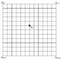
如图3所示,光电装置在预设测量路径上确定了五个测量点,在每个测量点进行测量数据的采集,共采集五组测量数据。当然,还可以在预设测量路径上采集其他数量的测量数据,比如采集六组、七组测量数据。As shown in Figure 3, the photoelectric device determines five measurement points on the preset measurement path, and collects measurement data at each measurement point, and collects five sets of measurement data in total. Of course, other quantities of measurement data may also be collected on the preset measurement path, for example, six or seven groups of measurement data may be collected.
S204:针对每个目标,多次不完全重复地选取预设组数的测量数据。S204: For each target, select a preset number of measurement data multiple times without complete repetition.
当预设测量路径上具有N个测量点时,多次不重复地选取m个测量点,即可以选取

S205:判断基于选取的预设组数的测量数据是否能确定目标的坐标。S205: Determine whether the coordinates of the target can be determined based on the selected preset number of measurement data.
当S205的判断结果为是时,即基于选取的预设组数的测量数据能确定目标的坐标,则执行S206:将所确定的目标的坐标作为目标的精确坐标。具体地,每组三个测量点基于空间两点距离的计算公式获得3个方程,3个方程联立求解获得目标坐标,该坐标即为目标的精确坐标。When the judgment result of S205 is yes, that is, the coordinates of the target can be determined based on the selected preset sets of measurement data, then perform S206: take the determined coordinates of the target as the precise coordinates of the target. Specifically, each group of three measurement points obtains three equations based on the calculation formula of the distance between two points in space, and the three equations are solved simultaneously to obtain the target coordinates, which are the precise coordinates of the target.
图4示出了选取三个测量点进行目标坐标计算的示意图,三个测量点分别为点A、点B、点C;目标为点O;点A至点O的距离为L1,点B至点O的距离为L2,点C至点O的距离为L3。目标坐标的具体求解方程如下:


由于每次数据采集对目标O的对准会有误差,加上激光测距的测量值有一定距离误差,因此存在目标坐标的多个求解方程组均无解的情况,即无法通过求解方程解算获取目标的精确坐标。Since there will be an error in the alignment of the target O for each data collection, and there is a certain distance error in the measured value of the laser ranging, there is a situation where there are no solutions for multiple solution equations of the target coordinates, that is, it is impossible to solve the problem by solving the equations. Calculate the exact coordinates of the target.
当S205的判断结果为否时,即基于选取的预设组数的测量数据不能确定目标的坐标,则执行S207:以预设距离误差对每个目标的初始坐标进行拟合,确定每个目标的精确坐标。具体地,S207中所提及的拟合过程采用多级拟合逼近法。其中,拟合逼近过程中的预设距离误差可依据测量设备的误差范围由人为提前设定,比如3米。When the judgment result of S205 is no, that is, the coordinates of the target cannot be determined based on the selected preset number of measurement data, then execute S207: Fit the initial coordinates of each target with the preset distance error, and determine each target exact coordinates. Specifically, the fitting process mentioned in S207 adopts a multi-stage fitting approximation method. Wherein, the preset distance error in the fitting and approximation process can be manually set in advance according to the error range of the measuring equipment, for example, 3 meters.
在S207中通过对初始坐标进行拟合,能够获得目标更加精确的坐标。本申请实施例以三级拟合逼近法为例,求取目标O的坐标值,具体方法的步骤描述如图5A和图5B所示。In S207, by fitting the initial coordinates, more precise coordinates of the target can be obtained. The embodiment of the present application takes the three-level fitting approximation method as an example to obtain the coordinate value of the target O. The steps of the specific method are described in FIG. 5A and FIG. 5B .
S501:以每个目标的初始坐标为拟合中心点。示例性地,图5C中
S502:执行拟合步骤。具体拟合步骤如图5B所示,包括步骤S506至S510。S502: Execute a fitting step. The specific fitting steps are shown in FIG. 5B , including steps S506 to S510.
S506:以预设间隔距离将拟合中心点在平面的两个垂直方向上分别扩展第一预设次数,获得矩阵平面。S506: Expand the fitting center point in the two perpendicular directions of the plane by a first preset number of times at a preset interval distance to obtain a matrix plane.
矩阵平面如图5C所示,在图5C中,第一预设次数为6次,平面的两个垂直方向为左右方向和上下方向。所以,图5C示例性地以预设间隔距离将拟合中心点A0在左右方向和上下方向分别扩展6次,获得矩阵平面,该矩阵平面包括一个矩阵点坐标系列
S507:以预设间隔距离将矩阵平面向上下分别扩展第二预设次数,获得拟合坐标矩阵。S507: Extending the matrix plane up and down for a second preset number of times at a preset interval distance to obtain a fitting coordinate matrix.
参照图5D所示,矩阵平面A0向上下分别扩展第二预设次数。在图5D中,第二预设次数为5次,扩展后共11个矩阵平面

S508:确定拟合坐标矩阵中的每个坐标与多个测量点之间的计算距离。S508: Determine the calculation distance between each coordinate in the fitting coordinate matrix and the plurality of measurement points.
示例性地,当测量点的数量为图3所示的5个时,分别计算拟合坐标矩阵中的每个坐标与5个测量点之间的计算距离,即计算拟合坐标矩阵中的每个坐标对应具体5个计算距离。Exemplarily, when the number of measurement points is 5 as shown in FIG. 3 , the calculation distance between each coordinate in the fitting coordinate matrix and the 5 measurement points is calculated respectively, that is, the distance between each coordinate in the fitting coordinate matrix is calculated. The coordinates correspond to the specific 5 calculated distances.
S509:求解每个计算距离与对应测量距离的误差,并确定拟合坐标矩阵中的每个坐标的多个误差的绝对值之和,获得误差矩阵。S509: Calculate the error between each calculated distance and the corresponding measured distance, and determine the sum of the absolute values of the multiple errors for each coordinate in the fitted coordinate matrix to obtain an error matrix.
示例性地,当计算拟合坐标矩阵中的每个坐标对应具体5个计算距离时,拟合坐标矩阵中的每个坐标的5个计算距离分别与对应的5个测量距离之间的误差,获得5个误差。由于误差可能同时存在正值和负值,为避免正负抵消,通过确定拟合坐标矩阵中的每个坐标的多个误差的绝对值之和来获得如下所示误差矩阵:Exemplarily, when calculating each coordinate in the fitted coordinate matrix corresponding to specific 5 calculated distances, the errors between the 5 calculated distances of each coordinate in the fitted coordinate matrix and the corresponding 5 measured distances, Get 5 errors. Since the error may have positive and negative values at the same time, in order to avoid positive and negative offsets, the error matrix as shown below is obtained by determining the sum of the absolute values of multiple errors for each coordinate in the fitted coordinate matrix:

S510:确定误差矩阵中最小值所对应的坐标。S510: Determine the coordinates corresponding to the minimum value in the error matrix.
S503:判断拟合步骤中的预设间隔距离是否达到预设距离误差。其中,预设距离误差由人为提前设定,比如可以设定为0.1米。拟合步骤可以循环执行多次,比如执行三次;第一次执行拟合步骤时,预设间隔距离设置为10米;第二次执行拟合步骤时,预设间隔距离设置为1米;第三次执行拟合步骤时,预设间隔距离设置为0.1米。S503: Determine whether the preset interval distance in the fitting step reaches a preset distance error. Wherein, the preset distance error is artificially set in advance, for example, it can be set to 0.1 meters. The fitting step can be executed repeatedly, for example, three times; when the fitting step is executed for the first time, the preset interval distance is set to 10 meters; when the fitting step is executed for the second time, the preset interval distance is set to 1 meter; When performing the fitting step three times, the preset separation distance was set to 0.1 m.
若S503的判断结果为否,即拟合步骤中的预设间隔距离未达到预设距离误差,执行S505:调小预设间隔距离,并将误差矩阵中最小值所对应的坐标作为拟合中心点。执行S505后,循环执行拟合步骤,直至拟合步骤中的预设间隔距离达到预设距离误差。若S503的判断结果为是,即拟合步骤中的预设间隔距离达到预设距离误差,执行S504:将误差矩阵中最小值所对应的坐标作为精确坐标。If the judgment result of S503 is no, that is, the preset interval distance in the fitting step does not reach the preset distance error, execute S505: reduce the preset interval distance, and use the coordinate corresponding to the minimum value in the error matrix as the fitting center point. After S505 is executed, the fitting step is executed cyclically until the preset interval distance in the fitting step reaches the preset distance error. If the judgment result of S503 is yes, that is, the preset interval distance in the fitting step reaches the preset distance error, execute S504: take the coordinate corresponding to the minimum value in the error matrix as the precise coordinate.
每个目标对应的多个测量点满足如下条件:每个目标的任意一个测量点与其他任意两个测量点组合形成的角度大于预设角度;在每个目标的任意三个测量点组成的三角形中,任意顶点到对边的距离大于或等于预设距离。其中,预设角度和预设距离都由人为提前设定,比如:预设角度可以在5°至170°之间取值,用户可根据需要具体设定,如预设角度设置为10°;预设距离可由人为提前设定,例如,可以人为设置为20米,也可以基于获得的测量点至目标的距离进行调节,测量点至目标的距离越大,预设距离越大。The multiple measurement points corresponding to each target meet the following conditions: the angle formed by the combination of any measurement point of each target and any other two measurement points is greater than the preset angle; the triangle formed by any three measurement points of each target , the distance from any vertex to the opposite side is greater than or equal to the preset distance. Among them, the preset angle and the preset distance are set in advance manually, for example: the preset angle can take a value between 5° and 170°, and the user can set it according to the needs, for example, the preset angle is set to 10°; The preset distance can be set artificially in advance, for example, it can be artificially set to 20 meters, or it can be adjusted based on the obtained distance from the measurement point to the target. The larger the distance from the measurement point to the target, the greater the preset distance.
每个目标均对应有多个测量点,比如图3所示的目标对应有五个测量点。任意一个测量点与其他任意两个测量点组合形成一个角度,任意三个测量点能够组成一个三角形。通过使用目标对应的测量点满足以上条件,避免测量点之间过于拥挤,进而使多组测量数据进行精确坐标计算时或初始坐标进行拟合时尽可能地消除测量误差,保证所获得的精确坐标具有较高的精度。Each target corresponds to multiple measurement points, for example, the target shown in FIG. 3 corresponds to five measurement points. Any one measurement point forms an angle with any other two measurement points, and any three measurement points can form a triangle. By using the measurement points corresponding to the target to meet the above conditions, the overcrowding between the measurement points can be avoided, and then the measurement error can be eliminated as much as possible when multiple sets of measurement data are used for accurate coordinate calculation or when the initial coordinates are fitted, so as to ensure the obtained accurate coordinates With higher precision.
示例性地,图4所示的三个测量点
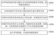
本申请实施例中的预设测量路径通过图7所示的步骤S701至S705生成,同时图6A至图6E形象地展示了预设测量路径的生成过程,下面以图6A至图6E为例对图7所示的步骤S701至S705进行说明。The preset measurement path in the embodiment of the present application is generated through the steps S701 to S705 shown in FIG. 7, and at the same time, FIG. 6A to FIG. Steps S701 to S705 shown in FIG. 7 are described.
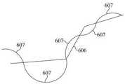
S701:以目标的初始坐标为圆心并以预设规划路径为切线,获得最佳视角点。如图6A所示,以目标601画圆,圆形区域与有源定位的预设规划路径602相切,获得与每个目标601对应的最佳视角点603。S701: Taking the initial coordinates of the target as the center of the circle and taking the preset planning path as the tangent, to obtain the best viewpoint. As shown in FIG. 6A , a circle is drawn with a
S702:以预设缓冲半径为每个最佳视角点建立缓冲范围。其中,预设缓冲半径由人为提前进行设定,比如预设缓冲半径为100米。如图6B所示,以最佳视角点603为圆心,以100米为预设缓冲半径,建立每个目标的缓冲范围604。S702: Establish a buffer range for each optimal view point with a preset buffer radius. Wherein, the preset buffer radius is manually set in advance, for example, the preset buffer radius is 100 meters. As shown in FIG. 6B , a
S703:对缓冲范围的多条切线进行并集运算,获得缓冲多边形。如图6C所示,切线并集运算后获得缓冲多边形605。S703: Perform a union operation on multiple tangents in the buffer range to obtain a buffer polygon. As shown in FIG. 6C , a
S704:沿缓冲多边形的中心分割线,每隔预设长度设置一段圆弧,并使相邻两个圆弧位于中心分割线的两侧。其中,预设长度由人为提前设定,比如预设长度设定为200米。图6C中形成了缓冲多边形605,如图6D所示,根据缓冲多边形605获得中心分割线606。如图6E所示,沿中心分割线606每个预设长度设置一段圆弧607,并且相邻圆弧607位于中心分割线606的两侧。S704: Along the central dividing line of the buffer polygon, set a section of circular arc at intervals of preset lengths, and make two adjacent circular arcs located on both sides of the central dividing line. Wherein, the preset length is manually set in advance, for example, the preset length is set to 200 meters. A
S705:组合多段圆弧,形成预设测量路径。S705: Combine multiple arcs to form a preset measurement path.
本申请实施例通过步骤S701至S705获得的预设测量路径,能够更加容易获得满足以上条件的测量点,方便了对目标的精确定位。In the embodiment of the present application, through the preset measurement path obtained in steps S701 to S705, it is easier to obtain measurement points satisfying the above conditions, which facilitates precise positioning of the target.
如图8所示,采集每个目标的大于三组测量数据,包括步骤S801和S802。As shown in FIG. 8 , collecting more than three sets of measurement data for each target includes steps S801 and S802 .
S801:将每两段相邻的圆弧按照预设比例划分为开始段、中间段和末尾段。比如,将每两段圆弧的前1/5划分为开始段,每两段圆弧的中间1/4划分为中间段,每两段圆弧的后1/5划分为末尾段。S801: Divide every two adjacent arcs into a start segment, a middle segment and an end segment according to a preset ratio. For example, the first 1/5 of every two arcs is divided into the start segment, the middle 1/4 of every two arcs is divided into the middle segment, and the last 1/5 of every two arcs is divided into the end segment.
S802:对每个目标在开始段和末尾段至少各采集一个测量数据,在中间段至少采集两个测量数据。也即,在对每个目标在开始段和末尾段至少各设置一个测量点,在中间段至少设置两个测量点。S802: For each target, at least one measurement data is collected in the beginning section and the end section, and at least two measurement data are collected in the middle section. That is, for each target, at least one measurement point is set in the beginning section and the end section, and at least two measurement points are set in the middle section.
通过在预设测量路径上采用S801和S802所示的方式设置的测量点更容易满足以上条件,对目标的定位也更加精确。The measurement points set in the manner shown in S801 and S802 on the preset measurement path are more likely to meet the above conditions, and the positioning of the target is also more accurate.
如图9所示,在预设测量路径上搜索并锁定需定位的目标包括步骤S901至S904。As shown in FIG. 9 , searching and locking the target to be positioned on the preset measurement path includes steps S901 to S904 .
S901:根据初始坐标和光电装置所处位置,确定目标所在方位。具体地,通过比较目标的初始位置和光电装置所处位置,便可以确定目标所在方位。比如:目标位于预设测量路径的左前方,并与预设测量路径的夹角为30°。S901: Determine the orientation of the target according to the initial coordinates and the location of the photoelectric device. Specifically, by comparing the initial position of the target with the position of the photoelectric device, the orientation of the target can be determined. For example: the target is located in the left front of the preset measurement path, and the included angle with the preset measurement path is 30°.
S902:控制光电装置旋转至目标所在方位。通过S801中确定的目标所在方位便可以获知后续如何控制光电装置进行旋转,通过将光电装置旋转至目标所在方位,使将要测量定位的目标位于光电装置的视场中。S902: Control the photoelectric device to rotate to the position of the target. How to control the photoelectric device to rotate subsequently can be known through the location of the target determined in S801. By rotating the photoelectric device to the location of the target, the target to be measured and positioned is located in the field of view of the photoelectric device.
S903:在光电装置的视场中进行搜索。S903: Search in the field of view of the optoelectronic device.
S904:搜索到目标后将光电装置的焦点移动至目标的中心。S904: After searching for the target, move the focus of the photoelectric device to the center of the target.
该方法还包括:在有源定位过程中采集目标的图像特征,形成目标特征库。S903具体为:利用目标特征库,在光电装置的视场中进行特征匹配。通过特征匹配能够确定光电装置的视场中哪部分为目标。比如,目标为越野汽车,目标特征库中包含车轮、车身形状等越野汽车特征,通过比较光电装置的视场中的各区域,将符合越野汽车特征的区域确定为目标,进而实现了对目标的搜索。The method also includes: collecting image features of the target during the active positioning process to form a target feature library. S903 is specifically: performing feature matching in the field of view of the optoelectronic device by using the target feature library. By feature matching it is possible to determine which part of the field of view of the optoelectronic device is the target. For example, if the target is an off-road vehicle, the target feature library contains the characteristics of the off-road vehicle such as wheels and body shape. By comparing the areas in the field of view of the photoelectric device, the area that meets the characteristics of the off-road vehicle is determined as the target, and then the target is realized. search.
本申请提供的方法还包括:统计有源定位在不同测量距离对应误差,形成误差分布表。如图10所示,在预设测量路径上搜索并锁定需定位的目标,该方法还包括步骤S1001和S1002。The method provided by the present application further includes: making statistics on corresponding errors of active positioning at different measurement distances, and forming an error distribution table. As shown in FIG. 10 , the method for searching and locking a target to be positioned on a preset measurement path further includes steps S1001 and S1002 .
S1001:调整光电装置的视场尺寸至有源定位时的视场尺寸。将搜索目标时的光电装置的视场尺寸还原至有源定位时的视场尺寸,为后续利用误差分布表提供了基础。S1001: Adjust the size of the field of view of the photoelectric device to the size of the field of view during active positioning. The size of the field of view of the photoelectric device when searching for targets is restored to the size of the field of view during active positioning, which provides a basis for the subsequent use of the error distribution table.
S1002:查找误差分布表,以当前距离的误差范围的预设倍数在光电装置的视场中搜索目标。其中,误差范围通过查找误差分布表获知,预设倍数由人为设定;比如,预设倍数为2倍。S1002: Look up the error distribution table, and search for the target in the field of view of the photoelectric device with a preset multiple of the error range of the current distance. Wherein, the error range is obtained by looking up the error distribution table, and the preset multiple is manually set; for example, the preset multiple is 2 times.
通过S1001和S1002缩小了搜索范围,不需要在光电装置的整个视场中进行寻找,进而能够缩短搜索时间,快速地搜索到目标。Through S1001 and S1002, the search range is narrowed, and it is not necessary to search in the entire field of view of the photoelectric device, so that the search time can be shortened, and the target can be searched quickly.
本申请实施例上述的方法通过多次不完全重复地选取预设组数的所述测量数据,或者对每个目标的初始坐标进行拟合来目标的精确坐标,大幅减小了定位误差,提高了对目标定位的精度。The above-mentioned method in the embodiment of the present application selects the measurement data of the preset number of times repeatedly, or performs fitting on the initial coordinates of each target to obtain the precise coordinates of the target, which greatly reduces the positioning error and improves the accuracy of the target. the accuracy of target positioning.
虽然本申请实施例提供了以上的方法步骤,但基于常规或者无创造性的劳动可以包括更多或者更少的操作步骤。另外,本申请实施例中列举的步骤顺序仅仅为众多步骤执行顺序中的一种方式,不代表唯一的执行顺序。在该运动过程中的目标定位方法执行时,可以按照本实施例或者附图所示的方法顺序执行或者并行执行(例如并行处理器或者多线程处理的环境)。Although the embodiments of the present application provide the above method steps, more or less operation steps may be included based on routine or non-inventive efforts. In addition, the sequence of steps enumerated in the embodiments of the present application is only one way of execution sequence of many steps, and does not represent the only execution sequence. When the target positioning method in the motion process is executed, it can be executed sequentially or in parallel according to the method shown in this embodiment or the drawings (for example, in a parallel processor or multi-thread processing environment).
如图11所示,本申请实施例还提供了一种运动过程中的目标定位装置1100,该运动过程中的目标定位装置1100包括路径模块1101、锁定模块1102、采集模块1103和计算模块1104。As shown in FIG. 11 , the embodiment of the present application also provides a target positioning device 1100 during motion, and the target positioning device 1100 during motion includes a path module 1101 , a locking module 1102 , a collection module 1103 and a calculation module 1104 .
路径模块1101用于沿预设规划路径对每个目标进行有源定位,获得每个目标的初始坐标,并基于目标的初始坐标获得预设测量路径。锁定模块1102用于在预设测量路径上,基于各目标的初始坐标搜索并锁定需定位的目标。采集模块1103用于沿预设测量路径运动过程中,采集每个目标的大于预设组数的测量数据;其中,测量数据包括测量点的位置信息,以及测量点至目标的测量距离。计算模块1104用于针对每个目标,多次不完全重复地选取预设组数的测量数据,并判断基于选取的预设组数的测量数据是否能确定目标的坐标;若能,则将所确定的目标的坐标作为目标的精确坐标;否则,以预设距离误差对每个目标的初始坐标进行拟合,确定每个目标的精确坐标。The path module 1101 is used for actively positioning each target along a preset planned path, obtaining initial coordinates of each target, and obtaining a preset measurement path based on the initial coordinates of the target. The locking module 1102 is used to search and lock the target to be positioned based on the initial coordinates of each target on the preset measurement path. The collection module 1103 is used to collect measurement data of each target greater than a preset number of groups during movement along the preset measurement path; wherein, the measurement data includes position information of the measurement point and the measurement distance from the measurement point to the target. The calculation module 1104 is used for selecting the measurement data of the preset number of groups repeatedly incompletely for each target, and judging whether the coordinates of the target can be determined based on the selected measurement data of the preset number of groups; The determined coordinates of the target are used as the precise coordinates of the target; otherwise, the initial coordinates of each target are fitted with a preset distance error to determine the precise coordinates of each target.
计算模块1104在用于以预设距离误差对每个目标的初始坐标进行拟合,确定每个目标的精确坐标时,具体用于:以每个目标的初始坐标为拟合中心点,执行拟合步骤;判断拟合步骤中的预设间隔距离是否达到预设距离误差;若未达到,调小预设间隔距离,并将误差矩阵中最小值所对应的坐标作为拟合中心点,循环执行拟合步骤;若达到,将误差矩阵中最小值所对应的坐标作为精确坐标;其中,拟合步骤包括:以预设间隔距离将拟合中心点在平面的两个垂直方向上分别扩展第一预设次数,获得矩阵平面;以预设间隔距离将矩阵平面向上下分别扩展第二预设次数,获得拟合坐标矩阵;确定拟合坐标矩阵中的每个坐标与多个测量点之间的计算距离;求解每个计算距离与对应测量距离的误差,并确定拟合坐标矩阵中的每个坐标的多个误差的绝对值之和,获得误差矩阵;确定误差矩阵中最小值所对应的坐标。When the calculation module 1104 is used to fit the initial coordinates of each target with a preset distance error and determine the precise coordinates of each target, it is specifically used to: take the initial coordinates of each target as the fitting center point, perform the fitting Fitting step; judge whether the preset interval distance in the fitting step reaches the preset distance error; if not, reduce the preset interval distance, and use the coordinate corresponding to the minimum value in the error matrix as the fitting center point, and execute in a loop Fitting step; if reached, the coordinates corresponding to the minimum value in the error matrix are used as precise coordinates; wherein, the fitting step includes: extending the fitting center point in the two vertical directions of the plane by the first The preset number of times is used to obtain the matrix plane; the matrix plane is extended up and down by the second preset number of preset intervals to obtain the fitted coordinate matrix; and the distance between each coordinate in the fitted coordinate matrix and a plurality of measurement points is determined Calculate the distance; solve the error between each calculated distance and the corresponding measured distance, and determine the sum of the absolute values of the multiple errors of each coordinate in the fitted coordinate matrix to obtain the error matrix; determine the coordinate corresponding to the minimum value in the error matrix .
每个目标对应的多个测量点满足如下条件:每个目标的任意一个测量点与其他任意两个测量点组合形成的角度大于预设角度;在每个目标的任意三个测量点组成的三角形中,任意顶点到对边的距离大于或等于预设距离。The multiple measurement points corresponding to each target meet the following conditions: the angle formed by the combination of any measurement point of each target and any other two measurement points is greater than the preset angle; the triangle formed by any three measurement points of each target , the distance from any vertex to the opposite side is greater than or equal to the preset distance.
路径模块1101用于基于目标的初始坐标获得预设测量路径时,具体用于:以目标的初始坐标为圆心并以预设规划路径为切线,获得最佳视角点;以预设缓冲半径为每个最佳视角点建立缓冲范围;对缓冲范围的多条切线进行并集运算,获得缓冲多边形;沿缓冲多边形的中心分割线,每隔预设长度设置一段圆弧,并使相邻两个圆弧位于中心分割线的两侧;组合多段圆弧,形成预设测量路径。When the path module 1101 is used to obtain the preset measurement path based on the initial coordinates of the target, it is specifically used to: take the initial coordinates of the target as the center of the circle and take the preset planning path as the tangent to obtain the best viewing angle point; use the preset buffer radius as each Create a buffer range from the best viewing point; perform a union operation on multiple tangents in the buffer range to obtain a buffer polygon; set a section of arc every preset length along the central dividing line of the buffer polygon, and make two adjacent circles The arc is located on both sides of the center dividing line; multiple arcs are combined to form a preset measurement path.
采集模块1103具体用于:将每两段相邻的圆弧按照预设比例划分为开始段、中间段和末尾段;对每个目标在开始段和末尾段至少各采集一个测量数据,在中间段至少采集两个测量数据。The acquisition module 1103 is specifically used to: divide every two adjacent circular arcs into a start segment, a middle segment and an end segment according to a preset ratio; collect at least one measurement data at the start segment and the end segment for each target, and at least one measurement data in the middle segment Acquire two measurements.
锁定模块1102具体用于:根据初始坐标和用于定位目标的光电装置所处位置,确定目标所在方位;控制光电装置旋转至目标所在方位;在光电装置的视场中进行搜索;搜索到目标后将光电装置的焦点移动至目标的中心。The locking module 1102 is specifically used to: determine the position of the target according to the initial coordinates and the position of the photoelectric device used to locate the target; control the photoelectric device to rotate to the position of the target; search in the field of view of the photoelectric device; Move the focus of the photoelectric device to the center of the target.
该运动过程中的目标定位装置1100还包括:特征模块,用于在有源定位过程中采集目标的图像特征,形成目标特征库;锁定模块1102在光电装置的视场中进行搜索,具体用于:利用目标特征库,在光电装置的视场中进行特征匹配。锁定模块1102还用于:调整光电装置的视场尺寸至有源定位时的视场尺寸;查找误差分布表,以当前距离的误差范围的预设倍数在光电装置的视场中搜索目标。The target positioning device 1100 in the movement process also includes: a feature module, which is used to collect the image features of the target during the active positioning process to form a target feature library; the locking module 1102 searches in the field of view of the photoelectric device, specifically for : Using the target feature library, feature matching is performed in the field of view of the optoelectronic device. The locking module 1102 is also used to: adjust the size of the field of view of the photoelectric device to the size of the field of view during active positioning; look up the error distribution table, and search the target in the field of view of the photoelectric device with a preset multiple of the error range of the current distance.
本申请实施例所述装置中的部分模块可以在由计算机执行的计算机可执行指令的一般上下文中描述,例如程序模块。一般地,程序模块包括执行特定任务或实现特定抽象数据类型的例程、程序、对象、组件、数据结构、类等。也可以在分布式计算环境中实践本申请,在这些分布式计算环境中,由通过通信网络而被连接的远程处理设备来执行任务。在分布式计算环境中,程序模块可以位于包括存储设备在内的本地和远程计算机存储介质中。Some modules in the apparatus described in the embodiments of the present application may be described in the general context of computer-executable instructions executed by a computer, such as program modules. Generally, program modules include routines, programs, objects, components, data structures, classes, etc. that perform particular tasks or implement particular abstract data types. The application may also be practiced in distributed computing environments where tasks are performed by remote processing devices that are linked through a communications network. In a distributed computing environment, program modules may be located in both local and remote computer storage media including storage devices.
本申请实施例还提供了一种计算机可读存储介质,计算机可读存储介质存储有计算机可读指令,计算机可读指令被处理器执行时实现本申请实施例以上提供的方法。具体地,上述的计算机可读存储介质包括但不限于随机存取存储器、只读存储器、缓存、硬盘或者存储卡。The embodiment of the present application also provides a computer-readable storage medium. The computer-readable storage medium stores computer-readable instructions. When the computer-readable instructions are executed by a processor, the method provided above in the embodiment of the present application is implemented. Specifically, the above-mentioned computer-readable storage medium includes, but is not limited to, random access memory, read-only memory, cache, hard disk or memory card.
通过以上的实施方式的描述可知,本领域的技术人员可以清楚地了解到本申请可借助软件加必需的硬件的方式来实现。基于这样的理解,本申请的技术方案本质上或者说对现有技术做出贡献的部分可以以软件产品的形式体现出来,也可以通过数据迁移的实施过程中体现出来。该计算机软件产品可以存储在存储介质中,如ROM/RAM、磁碟、光盘等,包括若干指令用以使得一台计算机设备执行本申实施例所述的方法。It can be known from the above description of the implementation manners that those skilled in the art can clearly understand that the present application can be implemented by means of software plus necessary hardware. Based on this understanding, the essence of the technical solution of this application or the part that contributes to the existing technology can be embodied in the form of software products, or it can be reflected in the implementation process of data migration. The computer software product can be stored in a storage medium, such as ROM/RAM, magnetic disk, optical disk, etc., and includes several instructions to enable a computer device to execute the method described in the embodiments of this application.
本说明书中的各个实施方式采用递进的方式描述,各个实施方式之间相同或相似的部分互相参见即可,每个实施方式重点说明的都是与其他实施方式的不同之处。本申请的全部或者部分可用于众多通用或专用的计算机系统环境或配置中。以上实施例仅用以说明本申请的技术方案,而非对本申请限制;尽管参照前述实施例对本申请进行了详细的说明,本领域普通技术人员应当理解:其依然可以对前述实施例所记载的技术方案进行修改,或者对其中部分或者全部技术特征进行等同替换;而这些修改或者替换,并不使相应技术方案的本质脱离本申请技术方案的范围。The various implementations in this specification are described in a progressive manner, the same or similar parts of the various implementations can be referred to each other, and each implementation focuses on the differences from other implementations. This application, in whole or in part, can be used in numerous general purpose or special purpose computer system environments or configurations. The above embodiments are only used to illustrate the technical solutions of the present application, rather than to limit the present application; although the present application has been described in detail with reference to the foregoing embodiments, those of ordinary skill in the art should understand that: it can still be described in the foregoing embodiments Modifications to the technical solutions, or equivalent replacement of some or all of the technical features; and these modifications or replacements do not make the essence of the corresponding technical solutions depart from the scope of the technical solutions of the present application.
Claims (10)
Priority Applications (1)
| Application Number | Priority Date | Filing Date | Title |
|---|---|---|---|
| CN202211423264.9ACN115493598B (en) | 2022-11-15 | 2022-11-15 | Target positioning method and device in motion process and storage medium |
Applications Claiming Priority (1)
| Application Number | Priority Date | Filing Date | Title |
|---|---|---|---|
| CN202211423264.9ACN115493598B (en) | 2022-11-15 | 2022-11-15 | Target positioning method and device in motion process and storage medium |
Publications (2)
| Publication Number | Publication Date |
|---|---|
| CN115493598Atrue CN115493598A (en) | 2022-12-20 |
| CN115493598B CN115493598B (en) | 2023-03-10 |
Family
ID=85115744
Family Applications (1)
| Application Number | Title | Priority Date | Filing Date |
|---|---|---|---|
| CN202211423264.9AActiveCN115493598B (en) | 2022-11-15 | 2022-11-15 | Target positioning method and device in motion process and storage medium |
Country Status (1)
| Country | Link |
|---|---|
| CN (1) | CN115493598B (en) |
Cited By (1)
| Publication number | Priority date | Publication date | Assignee | Title |
|---|---|---|---|---|
| CN116233804A (en)* | 2023-05-08 | 2023-06-06 | 北京瀚科智翔科技发展有限公司 | Unmanned aerial vehicle bee colony high-precision positioning system and method based on ad hoc network |
Citations (12)
| Publication number | Priority date | Publication date | Assignee | Title |
|---|---|---|---|---|
| CN106595668A (en)* | 2016-12-12 | 2017-04-26 | 中国航空工业集团公司洛阳电光设备研究所 | Passive location algorithm for electro-optical pod |
| US20180276847A1 (en)* | 2015-09-24 | 2018-09-27 | Apple Inc. | Systems and methods for localization using surface imaging |
| US20190195631A1 (en)* | 2017-12-22 | 2019-06-27 | Ubtech Robotics Corp | Positioning method, positioning device, and robot |
| CN110033480A (en)* | 2019-04-19 | 2019-07-19 | 西安应用光学研究所 | The airborne lidar for fluorescence target motion vectors estimation method of measurement is taken the photograph based on boat |
| CN110119190A (en)* | 2018-02-06 | 2019-08-13 | 广东虚拟现实科技有限公司 | Localization method, device, recognition and tracking system and computer-readable medium |
| CN111896914A (en)* | 2020-04-10 | 2020-11-06 | 中兴通讯股份有限公司 | Cooperative positioning method, device, equipment and storage medium |
| CN112179357A (en)* | 2020-09-25 | 2021-01-05 | 中国人民解放军国防科技大学 | Monocular camera-based visual navigation method and system for plane moving target |
| WO2021168841A1 (en)* | 2020-02-28 | 2021-09-02 | 华为技术有限公司 | Positioning method and apparatus |
| CN114119676A (en)* | 2022-01-24 | 2022-03-01 | 西安羚控电子科技有限公司 | Target detection tracking identification method and system based on multi-feature information fusion |
| CN114964264A (en)* | 2022-07-11 | 2022-08-30 | 东方空间技术(山东)有限公司 | Space target positioning method and device, computer equipment and storage medium |
| CN115066012A (en)* | 2022-02-25 | 2022-09-16 | 西安电子科技大学 | Multi-user anchor-free positioning method based on UWB |
| CN115120967A (en)* | 2022-07-20 | 2022-09-30 | Oppo广东移动通信有限公司 | Target positioning method, device, storage medium and terminal |
- 2022
- 2022-11-15CNCN202211423264.9Apatent/CN115493598B/enactiveActive
Patent Citations (13)
| Publication number | Priority date | Publication date | Assignee | Title |
|---|---|---|---|---|
| US20180276847A1 (en)* | 2015-09-24 | 2018-09-27 | Apple Inc. | Systems and methods for localization using surface imaging |
| CN106595668A (en)* | 2016-12-12 | 2017-04-26 | 中国航空工业集团公司洛阳电光设备研究所 | Passive location algorithm for electro-optical pod |
| US20190195631A1 (en)* | 2017-12-22 | 2019-06-27 | Ubtech Robotics Corp | Positioning method, positioning device, and robot |
| CN110119190A (en)* | 2018-02-06 | 2019-08-13 | 广东虚拟现实科技有限公司 | Localization method, device, recognition and tracking system and computer-readable medium |
| CN110033480A (en)* | 2019-04-19 | 2019-07-19 | 西安应用光学研究所 | The airborne lidar for fluorescence target motion vectors estimation method of measurement is taken the photograph based on boat |
| WO2021168841A1 (en)* | 2020-02-28 | 2021-09-02 | 华为技术有限公司 | Positioning method and apparatus |
| WO2021203871A1 (en)* | 2020-04-10 | 2021-10-14 | 中兴通讯股份有限公司 | Cooperative positioning method and apparatus, device, and storage medium |
| CN111896914A (en)* | 2020-04-10 | 2020-11-06 | 中兴通讯股份有限公司 | Cooperative positioning method, device, equipment and storage medium |
| CN112179357A (en)* | 2020-09-25 | 2021-01-05 | 中国人民解放军国防科技大学 | Monocular camera-based visual navigation method and system for plane moving target |
| CN114119676A (en)* | 2022-01-24 | 2022-03-01 | 西安羚控电子科技有限公司 | Target detection tracking identification method and system based on multi-feature information fusion |
| CN115066012A (en)* | 2022-02-25 | 2022-09-16 | 西安电子科技大学 | Multi-user anchor-free positioning method based on UWB |
| CN114964264A (en)* | 2022-07-11 | 2022-08-30 | 东方空间技术(山东)有限公司 | Space target positioning method and device, computer equipment and storage medium |
| CN115120967A (en)* | 2022-07-20 | 2022-09-30 | Oppo广东移动通信有限公司 | Target positioning method, device, storage medium and terminal |
Non-Patent Citations (2)
| Title |
|---|
| 周前飞等: "机载光电成像平台的多目标自主定位系统研究", 《光学学报》* |
| 张少杰等: "无人直升机目标感知跟踪技术分析", 《中国科技信息》* |
Cited By (2)
| Publication number | Priority date | Publication date | Assignee | Title |
|---|---|---|---|---|
| CN116233804A (en)* | 2023-05-08 | 2023-06-06 | 北京瀚科智翔科技发展有限公司 | Unmanned aerial vehicle bee colony high-precision positioning system and method based on ad hoc network |
| CN116233804B (en)* | 2023-05-08 | 2023-07-14 | 北京瀚科智翔科技发展有限公司 | Unmanned aerial vehicle bee colony high-precision positioning system and method based on ad hoc network |
Also Published As
| Publication number | Publication date |
|---|---|
| CN115493598B (en) | 2023-03-10 |
Similar Documents
| Publication | Publication Date | Title |
|---|---|---|
| KR101905052B1 (en) | Drone for maintaining formation of swarm flight and method thereof | |
| US10962650B2 (en) | Polyhedral geofences | |
| US10509417B2 (en) | Flight planning for unmanned aerial tower inspection with long baseline positioning | |
| JP2023072064A (en) | Performing 3d reconstruction via unmanned aerial vehicle | |
| US20120314032A1 (en) | Method for pilot assistance for the landing of an aircraft in restricted visibility | |
| CN113066120B (en) | Intelligent pole and tower inclination detection method based on machine vision | |
| Roca et al. | Lidar-equipped uav for building information modelling | |
| CN109584264B (en) | Unmanned aerial vehicle vision guiding aerial refueling method based on deep learning | |
| CN111649723A (en) | Method and device for close-to-photography 3D track and attitude planning for complex terrain | |
| CN111413708A (en) | Lidar-based UAV autonomous identification and landing site selection method | |
| US20210200246A1 (en) | Method and system for determining the position of a moving object | |
| US12148205B2 (en) | Contour scanning with an unmanned aerial vehicle | |
| Lauterbach et al. | The Eins3D project—Instantaneous UAV-based 3D mapping for Search and Rescue applications | |
| WO2022193106A1 (en) | Method for fusing gps with laser radar through inertia measurement parameter for positioning | |
| CN111665508A (en) | Helicopter-mounted terrain following and avoiding visual navigation system and navigation method | |
| KR20220163227A (en) | Drone used 3d mapping method | |
| CN109669474B (en) | Adaptive hovering position optimization algorithm for multi-rotor UAV based on prior knowledge | |
| CN108827295A (en) | Miniature drone method for self-locating based on wireless sensor network and inertial navigation | |
| WO2021007855A1 (en) | Base station, photo-control-point positioning method, electronic device and computer readable medium | |
| CN115493598B (en) | Target positioning method and device in motion process and storage medium | |
| Curro et al. | Automated aerial refueling position estimation using a scanning lidar | |
| CN109163718A (en) | A kind of unmanned plane autonomous navigation method towards groups of building | |
| CN114755690A (en) | A laser radar-based rail identification and positioning method (30758) | |
| CN206209409U (en) | UAV control system and UAV | |
| CN113340272A (en) | Ground target real-time positioning method based on micro-group of unmanned aerial vehicle |
Legal Events
| Date | Code | Title | Description |
|---|---|---|---|
| PB01 | Publication | ||
| PB01 | Publication | ||
| SE01 | Entry into force of request for substantive examination | ||
| SE01 | Entry into force of request for substantive examination | ||
| GR01 | Patent grant | ||
| GR01 | Patent grant |