CN115492747A - Fluid drive type diaphragm pump and adjusting system thereof - Google Patents
Fluid drive type diaphragm pump and adjusting system thereofDownload PDFInfo
- Publication number
- CN115492747A CN115492747ACN202211442235.7ACN202211442235ACN115492747ACN 115492747 ACN115492747 ACN 115492747ACN 202211442235 ACN202211442235 ACN 202211442235ACN 115492747 ACN115492747 ACN 115492747A
- Authority
- CN
- China
- Prior art keywords
- fluid
- diaphragm
- diaphragm pump
- output
- housing
- Prior art date
- Legal status (The legal status is an assumption and is not a legal conclusion. Google has not performed a legal analysis and makes no representation as to the accuracy of the status listed.)
- Granted
Links
- 239000012530fluidSubstances0.000titleclaimsabstractdescription327
- 239000007788liquidSubstances0.000claimsabstractdescription173
- 238000009434installationMethods0.000claimsabstractdescription12
- 239000012528membraneSubstances0.000claimsdescription82
- 230000008859changeEffects0.000claimsdescription59
- 238000000034methodMethods0.000claimsdescription43
- 230000008569processEffects0.000claimsdescription38
- 238000007789sealingMethods0.000claimsdescription29
- 238000001514detection methodMethods0.000claimsdescription22
- 210000004204blood vesselAnatomy0.000claimsdescription18
- 230000000638stimulationEffects0.000claimsdescription17
- 238000004891communicationMethods0.000claimsdescription2
- 230000003750conditioning effectEffects0.000claimsdescription2
- 238000004519manufacturing processMethods0.000abstractdescription9
- 230000002829reductive effectEffects0.000abstractdescription3
- 230000002792vascularEffects0.000description17
- 230000010349pulsationEffects0.000description10
- 230000000694effectsEffects0.000description9
- 239000000463materialSubstances0.000description9
- 239000008280bloodSubstances0.000description6
- 210000004369bloodAnatomy0.000description6
- 238000010586diagramMethods0.000description6
- 230000001276controlling effectEffects0.000description5
- 230000003205diastolic effectEffects0.000description4
- 239000000203mixtureSubstances0.000description4
- 230000008602contractionEffects0.000description3
- 230000003247decreasing effectEffects0.000description3
- 230000036961partial effectEffects0.000description3
- 238000003466weldingMethods0.000description3
- 230000006835compressionEffects0.000description2
- 238000007906compressionMethods0.000description2
- 238000001125extrusionMethods0.000description2
- 230000000670limiting effectEffects0.000description2
- 230000002572peristaltic effectEffects0.000description2
- 238000005381potential energyMethods0.000description2
- 230000001105regulatory effectEffects0.000description2
- 230000001052transient effectEffects0.000description2
- 206010002329AneurysmDiseases0.000description1
- 208000031481Pathologic ConstrictionDiseases0.000description1
- 208000007536ThrombosisDiseases0.000description1
- 206010060872Transplant failureDiseases0.000description1
- 230000000712assemblyEffects0.000description1
- 238000000429assemblyMethods0.000description1
- 230000006399behaviorEffects0.000description1
- 230000003139buffering effectEffects0.000description1
- 230000002500effect on skinEffects0.000description1
- 206010020718hyperplasiaDiseases0.000description1
- 238000002513implantationMethods0.000description1
- 238000001802infusionMethods0.000description1
- 230000003993interactionEffects0.000description1
- 238000012986modificationMethods0.000description1
- 230000004048modificationEffects0.000description1
- 238000011160researchMethods0.000description1
- 230000002441reversible effectEffects0.000description1
- 230000000630rising effectEffects0.000description1
- 208000037804stenosisDiseases0.000description1
- 230000036262stenosisEffects0.000description1
- 238000004381surface treatmentMethods0.000description1
- 238000012360testing methodMethods0.000description1
- 230000009466transformationEffects0.000description1
Images


Classifications
- F—MECHANICAL ENGINEERING; LIGHTING; HEATING; WEAPONS; BLASTING
- F04—POSITIVE - DISPLACEMENT MACHINES FOR LIQUIDS; PUMPS FOR LIQUIDS OR ELASTIC FLUIDS
- F04B—POSITIVE-DISPLACEMENT MACHINES FOR LIQUIDS; PUMPS
- F04B43/00—Machines, pumps, or pumping installations having flexible working members
- F04B43/02—Machines, pumps, or pumping installations having flexible working members having plate-like flexible members, e.g. diaphragms
- F04B43/06—Pumps having fluid drive
- C—CHEMISTRY; METALLURGY
- C12—BIOCHEMISTRY; BEER; SPIRITS; WINE; VINEGAR; MICROBIOLOGY; ENZYMOLOGY; MUTATION OR GENETIC ENGINEERING
- C12M—APPARATUS FOR ENZYMOLOGY OR MICROBIOLOGY; APPARATUS FOR CULTURING MICROORGANISMS FOR PRODUCING BIOMASS, FOR GROWING CELLS OR FOR OBTAINING FERMENTATION OR METABOLIC PRODUCTS, i.e. BIOREACTORS OR FERMENTERS
- C12M21/00—Bioreactors or fermenters specially adapted for specific uses
- C12M21/08—Bioreactors or fermenters specially adapted for specific uses for producing artificial tissue or for ex-vivo cultivation of tissue
- C—CHEMISTRY; METALLURGY
- C12—BIOCHEMISTRY; BEER; SPIRITS; WINE; VINEGAR; MICROBIOLOGY; ENZYMOLOGY; MUTATION OR GENETIC ENGINEERING
- C12M—APPARATUS FOR ENZYMOLOGY OR MICROBIOLOGY; APPARATUS FOR CULTURING MICROORGANISMS FOR PRODUCING BIOMASS, FOR GROWING CELLS OR FOR OBTAINING FERMENTATION OR METABOLIC PRODUCTS, i.e. BIOREACTORS OR FERMENTERS
- C12M35/00—Means for application of stress for stimulating the growth of microorganisms or the generation of fermentation or metabolic products; Means for electroporation or cell fusion
- C12M35/04—Mechanical means, e.g. sonic waves, stretching forces, pressure or shear stimuli
- C—CHEMISTRY; METALLURGY
- C12—BIOCHEMISTRY; BEER; SPIRITS; WINE; VINEGAR; MICROBIOLOGY; ENZYMOLOGY; MUTATION OR GENETIC ENGINEERING
- C12M—APPARATUS FOR ENZYMOLOGY OR MICROBIOLOGY; APPARATUS FOR CULTURING MICROORGANISMS FOR PRODUCING BIOMASS, FOR GROWING CELLS OR FOR OBTAINING FERMENTATION OR METABOLIC PRODUCTS, i.e. BIOREACTORS OR FERMENTERS
- C12M41/00—Means for regulation, monitoring, measurement or control, e.g. flow regulation
- F—MECHANICAL ENGINEERING; LIGHTING; HEATING; WEAPONS; BLASTING
- F04—POSITIVE - DISPLACEMENT MACHINES FOR LIQUIDS; PUMPS FOR LIQUIDS OR ELASTIC FLUIDS
- F04B—POSITIVE-DISPLACEMENT MACHINES FOR LIQUIDS; PUMPS
- F04B49/00—Control, e.g. of pump delivery, or pump pressure of, or safety measures for, machines, pumps, or pumping installations, not otherwise provided for, or of interest apart from, groups F04B1/00 - F04B47/00
- F04B49/06—Control using electricity
Landscapes
- Engineering & Computer Science (AREA)
- Health & Medical Sciences (AREA)
- Life Sciences & Earth Sciences (AREA)
- Chemical & Material Sciences (AREA)
- Wood Science & Technology (AREA)
- Organic Chemistry (AREA)
- Bioinformatics & Cheminformatics (AREA)
- Zoology (AREA)
- General Engineering & Computer Science (AREA)
- Genetics & Genomics (AREA)
- Biomedical Technology (AREA)
- Biotechnology (AREA)
- Sustainable Development (AREA)
- Biochemistry (AREA)
- General Health & Medical Sciences (AREA)
- Microbiology (AREA)
- Mechanical Engineering (AREA)
- Analytical Chemistry (AREA)
- Molecular Biology (AREA)
- Cell Biology (AREA)
- Reciprocating Pumps (AREA)
Abstract
Description
Translated fromChinese技术领域technical field
本申请涉及隔膜泵技术领域,具体而言,涉及一种流体驱动式隔膜泵及其调节系统。The present application relates to the technical field of diaphragm pumps, in particular to a fluid-driven diaphragm pump and its adjustment system.
背景技术Background technique
组织工程血管的力学性能是影响其作为可移植物的重要标准之一。而目前组织工程血管与原生血管的力学性能差异较大,如抗爆破强度不足,顺应性不匹配,造成植入后不同程度的血栓形成与狭窄以及动脉瘤的发生,进而导致内膜增生与通畅率低,最终致使移植失败。The mechanical properties of tissue engineered blood vessels are one of the important criteria that affect their use as grafts. At present, the mechanical properties of tissue engineered blood vessels and native blood vessels are quite different, such as insufficient blast resistance and mismatched compliance, resulting in different degrees of thrombosis and stenosis after implantation and the occurrence of aneurysms, which in turn lead to intimal hyperplasia and patency. The rate is low, which eventually leads to transplant failure.
大量研究表明组织工程血管在培养过程中受到应力参数的调控。由于受限于动力来源,目前还无法在力学培养参数上进行充分探索,导致目前组织工程血管培养过程中的力学培养参数得不到优化,影响其进一步的转化研究。Numerous studies have shown that tissue engineered blood vessels are regulated by stress parameters during culture. Due to the limitation of the power source, it is still impossible to fully explore the mechanical culture parameters, which leads to the inability to optimize the mechanical culture parameters in the current tissue engineering blood vessel culture process, which affects its further transformation research.
现有技术一般采用蠕动泵作为组织工程血管培养的液体应力施加源,但存在成本高、液体压力控制不准确等缺点,其中,液体压力控制不准确表现为:现有的蠕动泵是基于调节转子的转速估算来改变管路中的液体流量的,但在改变液体流量的同时改变了液体的流量变化的压力和周期,无法单独地对液体流量和压力进行调节,且蠕动泵的转子只能匀速转动,也无法形式调节液体压力上升与下降的时间比值以模拟血管按照特定的舒张收缩进行血液输送;而工业上应用的隔膜泵属于一种流体输送装置,能实现液体流量的准确控制,但存在结构复杂、体积大等缺点,且一般采用机械式驱动控制,提供的压力相关参数与组织工程血管所需的力学环境不匹配;若能提供一种适用于组织工程血管培养、结构简单、且能根据液体状态控制液体输出压力的隔膜泵便能解决上述问题。In the prior art, peristaltic pumps are generally used as the source of liquid stress for tissue engineering blood vessel culture, but there are disadvantages such as high cost and inaccurate liquid pressure control. The speed estimation is used to change the liquid flow in the pipeline, but the pressure and cycle of the liquid flow change are changed while changing the liquid flow, and the liquid flow and pressure cannot be adjusted separately, and the rotor of the peristaltic pump can only be at a constant speed It is impossible to adjust the time ratio of the rise and fall of the liquid pressure in the form of rotation, so as to simulate the blood transport of the blood vessel according to the specific relaxation and contraction; the diaphragm pump used in industry is a kind of fluid delivery device, which can realize the accurate control of the liquid flow, but there are However, it has the disadvantages of complex structure and large volume, and generally adopts mechanical drive control, and the pressure-related parameters provided do not match the mechanical environment required by tissue engineering blood vessels; A diaphragm pump that controls the output pressure of the liquid according to the state of the liquid can solve the above problems.
针对上述问题,目前尚未有有效的技术解决方案。For the above problems, there is no effective technical solution at present.
发明内容Contents of the invention
本申请的目的在于提供一种流体驱动式隔膜泵及其调节系统,适用于组织工程血管培养且具有液体压力控制准确、简单轻便、体积小、制造成本低的特点。The purpose of this application is to provide a fluid-driven diaphragm pump and its adjustment system, which are suitable for tissue engineering blood vessel culture and have the characteristics of accurate liquid pressure control, simplicity, portability, small volume, and low manufacturing cost.
第一方面,本申请提供了一种流体驱动式隔膜泵,应用于组织工程血管培养过程的生物反应器中,所述流体驱动式隔膜泵包括第一壳体、第二壳体和隔膜组件,所述第一壳体与第二壳体扣接固定,所述隔膜组件可拆卸地密封安装在所述第一壳体和所述第二壳体之间的扣接端上,并分别与所述第一壳体和第二壳体围合构成第一流体腔和第二流体腔,所述第一壳体上设有与第一流体腔连通且为朝向所述隔膜组件设置的动力流体进出口,所述第二壳体上设有与所述第二流体腔连通且为朝向所述隔膜组件设置的输出液进液口和输出液出液口,所述第二壳体上还设有与所述第二流体腔连通的第一压力检测口,所述输出液进液口和所述输出液出液口内均设有单向阀。In a first aspect, the present application provides a fluid-driven diaphragm pump, which is applied in a bioreactor in the tissue engineering blood vessel culture process, and the fluid-driven diaphragm pump includes a first housing, a second housing and a diaphragm assembly, The first housing is buckled and fixed to the second housing, and the diaphragm assembly is detachably and hermetically installed on the buckled end between the first housing and the second housing, and is respectively connected to the second housing. The first housing and the second housing enclose a first fluid chamber and a second fluid chamber, and the first housing is provided with a power fluid inlet and outlet that communicates with the first fluid chamber and is disposed toward the diaphragm assembly, The second housing is provided with an output liquid inlet and an output liquid outlet that communicate with the second fluid chamber and are disposed toward the diaphragm assembly, and the second housing is also provided with a The first pressure detection port connected to the second fluid chamber, the output liquid inlet and the output liquid outlet are both provided with check valves.
本申请的流体驱动式隔膜泵基于第一壳体和第二壳体扣合安装的隔膜组件构成了隔膜泵输出液输出的结构主体,有效减少了隔膜泵的结构组成并降低了结构复杂度,具有结构简单轻便、体积小、制造成本低的特点;此外,隔膜组件基于第一壳体和第二壳体的扣接端进行密封安装,能根据使用需求快速拆卸替换不同疲劳性能、力学性能、形状的隔膜组件。The fluid-driven diaphragm pump of the present application is based on the diaphragm assembly snap-fitted by the first housing and the second housing to form the structural main body of the diaphragm pump output liquid output, which effectively reduces the structural composition and structural complexity of the diaphragm pump. It has the characteristics of simple and light structure, small size, and low manufacturing cost; in addition, the diaphragm assembly is sealed and installed based on the buckle ends of the first shell and the second shell, and can be quickly disassembled and replaced according to the needs of use. shape of the diaphragm assembly.
所述的流体驱动式隔膜泵,其中,所述隔膜组件包括第一膜体和第二膜体,所述第一膜体中部焊接固定在所述第二膜体上,所述第一膜体的边缘和所述第二膜体的边缘之间设有密封圈。The fluid-driven diaphragm pump, wherein the diaphragm assembly includes a first membrane body and a second membrane body, the middle part of the first membrane body is welded and fixed on the second membrane body, and the first membrane body A sealing ring is provided between the edge of the second membrane body and the edge of the second membrane body.
该示例的流体驱动式隔膜泵采用第一壳体-第一膜体-密封圈-第二膜体-第二壳体的接触连接方式,实现了隔膜组件的可拆卸安装,使得本申请的流体驱动式隔膜泵通过扣接第一壳体和第二壳体便能直接完成隔膜组件的密封安装,通过解锁第一壳体和第二壳体的扣接状态便能快速完成隔膜组件的拆卸。The fluid-driven diaphragm pump of this example adopts the contact connection mode of the first housing-the first membrane body-seal ring-the second membrane body-the second housing, which realizes the detachable installation of the diaphragm assembly, so that the fluid of the application The driven diaphragm pump can directly complete the sealing installation of the diaphragm assembly by buckling the first housing and the second housing, and can quickly complete the disassembly of the diaphragm assembly by unlocking the buckled state of the first housing and the second housing.
所述的流体驱动式隔膜泵,其中,所述第一膜体与所述第一壳体螺纹连接,和/或所述第二膜体与所述第二壳体螺纹连接。In the fluid-driven diaphragm pump, the first membrane body is threadedly connected to the first casing, and/or the second membrane body is threadedly connected to the second casing.
所述的流体驱动式隔膜泵,其中,在所述隔膜组件处于自然状态下,所述第二膜体中部呈朝向所述第一流体腔凸出的球面状。The fluid-driven diaphragm pump, wherein, when the diaphragm assembly is in a natural state, the middle part of the second diaphragm body is in a spherical shape protruding toward the first fluid cavity.
所述的流体驱动式隔膜泵,其中,所述动力流体进出口正对所述输出液进液口。In the fluid-driven diaphragm pump, the power fluid inlet and outlet are facing the output liquid inlet.
所述的流体驱动式隔膜泵,其中,所述输出液进液口和所述输出液出液口均包括第一管和第二管,所述第一管一端与所述第二流体腔连通,所述单向阀可拆卸的安装在所述第一管另一端,所述第二管一端固定在所述第一管和单向阀外周,所述第二管另一端具有束流管段。The fluid-driven diaphragm pump, wherein, the output liquid inlet and the output liquid outlet both include a first tube and a second tube, and one end of the first tube communicates with the second fluid chamber , the one-way valve is detachably mounted on the other end of the first tube, one end of the second tube is fixed on the first tube and the outer periphery of the one-way valve, and the other end of the second tube has a flow tube section.
所述的流体驱动式隔膜泵,其中,所述第一壳体还设有与所述第一流体腔连通的第二压力检测口。In the fluid-driven diaphragm pump, the first housing is further provided with a second pressure detection port communicating with the first fluid chamber.
所述的流体驱动式隔膜泵,其中,所述第一壳体通过螺栓固定在所述第二壳体上,且其一端插套在所述第二壳体内并与所述第二壳体内壁紧贴。In the fluid-driven diaphragm pump, the first housing is fixed on the second housing by bolts, and one end of the first housing is inserted into the second housing and connected to the inner wall of the second housing. cling.
第二方面,本申请还提供了一种流体驱动式隔膜泵的调节系统,应用于组织工程血管培养过程的生物反应器中,所述调节系统包括流体驱动式隔膜泵,所述流体驱动式隔膜泵包括:所述隔膜泵包括第一壳体、第二壳体和隔膜组件,所述第一壳体和第二壳体扣接,所述隔膜组件可拆卸地密封安装在所述第一壳体和所述第二壳体之间,并分别与所述第一壳体和第二壳体围合构成第一流体腔和第二流体腔,所述第一壳体上设有与第一流体腔连通且为朝向所述隔膜组件设置的动力流体进出口,所述第二壳体上设有与所述第二流体腔连通且为朝向所述隔膜组件设置的输出液进液口和输出液出液口,所述第二壳体上还设有与所述第二流体腔连通的第一压力检测口,所述输出液进液口和所述输出液出液口内均设有单向阀;In the second aspect, the present application also provides an adjustment system of a fluid-driven diaphragm pump, which is applied to a bioreactor in the tissue engineering blood vessel culture process, the adjustment system includes a fluid-driven diaphragm pump, and the fluid-driven diaphragm The pump includes: the diaphragm pump includes a first housing, a second housing and a diaphragm assembly, the first housing and the second housing are fastened, and the diaphragm assembly is detachably mounted on the first housing between the body and the second housing, and are respectively enclosed with the first housing and the second housing to form a first fluid chamber and a second fluid chamber, and the first housing is provided with the first fluid chamber communicated with the power fluid inlet and outlet set towards the diaphragm assembly, and the second housing is provided with an output liquid inlet and an output liquid outlet which communicate with the second fluid chamber and are set towards the diaphragm assembly. A liquid port, the second housing is also provided with a first pressure detection port communicating with the second fluid chamber, and a check valve is provided in the output liquid inlet and the output liquid outlet;
所述调节系统还包括:The adjustment system also includes:
压力传感器,与所述第一压力检测口连接,用于获取所述第二流体腔内液体的压力变化信息;a pressure sensor, connected to the first pressure detection port, and used to acquire pressure change information of the liquid in the second fluid chamber;
输出液供应组件,与所述输出液进液口连接;an output liquid supply component connected to the output liquid inlet;
动力流体供应组件,与所述动力流体进出口连接,用于周期性控制动力流体进出所述第一流体腔;a power fluid supply assembly, connected to the power fluid inlet and outlet, for periodically controlling the power fluid to enter and exit the first fluid chamber;
控制器,与所述压力传感器和所述动力流体供应组件电性连接;a controller electrically connected to the pressure sensor and the motive fluid supply assembly;
所述控制器用于根据所述压力变化信息、预设的力学刺激参数信息和舒张收缩时间比信息控制所述流体驱动式隔膜泵进行输出。The controller is used for controlling the fluid-driven diaphragm pump to output according to the pressure change information, the preset mechanical stimulation parameter information and the diastolic-systolic time ratio information.
所述的流体驱动式隔膜泵的调节系统,其中,所述力学刺激参数信息包括液体压力波形的周期信息、峰值信息。In the fluid-driven diaphragm pump adjustment system, the mechanical stimulation parameter information includes period information and peak information of the liquid pressure waveform.
本申请的流体驱动式隔膜泵的调节系统,用于控制第一方面提供的流体驱动式隔膜泵运行以产生符合预期脉动的输出液来供血管组织培养设备培养血管组织,该流体驱动式隔膜泵具有结构简单轻便、体积小、制造成本低的特点;同时,本申请的流体驱动式隔膜泵的调节系统能基于压力传感器获取第一流体腔内的压力变化信息获取输出液的脉动输出状态,通过流体控制液体输出的方式能更准确地对输出液的输出状态进行控制,从而输送出符合预期的流量、压力、频率等特性的输出液。The regulating system of the fluid-driven diaphragm pump of the present application is used to control the operation of the fluid-driven diaphragm pump provided in the first aspect to produce an output liquid that meets the expected pulsation for vascular tissue culture equipment to cultivate vascular tissue. The fluid-driven diaphragm pump It has the characteristics of simple and portable structure, small volume, and low manufacturing cost; at the same time, the adjustment system of the fluid-driven diaphragm pump of the present application can obtain the pulsating output state of the output liquid based on the pressure change information in the first fluid chamber obtained by the pressure sensor, through the fluid The method of controlling the liquid output can more accurately control the output state of the output liquid, so as to deliver the output liquid that meets the expected flow, pressure, frequency and other characteristics.
由上可知,本申请提供了一种流体驱动式隔膜泵及其调节系统,其中,流体驱动式隔膜泵基于第一流体腔输入输出流体实现输出液的脉动输出,能更准确地模拟血液脉动为血管组织培养设备供应输出液;其次,基于第一壳体和第二壳体扣合安装的隔膜组件构成了隔膜泵输出液输出的结构主体,有效减少了隔膜泵的结构组成并降低了结构复杂度,具有结构简单轻便、体积小、制造成本低的特点;此外,隔膜组件基于第一壳体和第二壳体的扣接端进行密封安装,能根据使用需求快速拆卸替换不同疲劳性能、力学性能、形状的隔膜组件,使得本申请的流体驱动式隔膜泵具有适用范围广的特点。As can be seen from the above, the present application provides a fluid-driven diaphragm pump and its adjustment system, wherein the fluid-driven diaphragm pump realizes the pulsating output of the output liquid based on the input and output of the first fluid chamber, which can more accurately simulate blood pulsation as a blood vessel The tissue culture equipment supplies the output liquid; secondly, the diaphragm assembly based on the fastening installation of the first housing and the second housing constitutes the structural main body of the output liquid output of the diaphragm pump, which effectively reduces the structural composition and structural complexity of the diaphragm pump , has the characteristics of simple and light structure, small size, and low manufacturing cost; in addition, the diaphragm assembly is sealed and installed based on the buckle ends of the first shell and the second shell, and can be quickly disassembled and replaced according to the needs of use. Different fatigue performance, mechanical properties , shape of the diaphragm assembly, so that the fluid-driven diaphragm pump of the present application has the characteristics of a wide range of applications.
附图说明Description of drawings
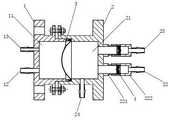
图1为本申请实施例提供的流体驱动式隔膜泵的正向剖视结构示意图。FIG. 1 is a schematic diagram of a front sectional structure of a fluid-driven diaphragm pump provided by an embodiment of the present application.
图2为第一膜体与第二膜体的组合结构示意图。Fig. 2 is a schematic diagram of the combined structure of the first membrane body and the second membrane body.
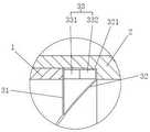
图3为一些实施例中隔膜组件、第一壳体和第二壳体连接的局部结构示意图。Fig. 3 is a partial structural schematic diagram of the connection of the diaphragm assembly, the first housing and the second housing in some embodiments.
图4为另一些实施例中隔膜组件、第一壳体和第二壳体连接的局部结构示意图。Fig. 4 is a partial structural schematic diagram of the connection of the diaphragm assembly, the first housing and the second housing in other embodiments.
图5为再一些实施例中隔膜组件、第一壳体和第二壳体连接的局部结构示意图。Fig. 5 is a partial structural schematic diagram of the connection of the diaphragm assembly, the first housing and the second housing in some other embodiments.
图6为流体驱动式隔膜泵的调节系统的结构示意图。Fig. 6 is a structural schematic diagram of an adjustment system of a fluid-driven diaphragm pump.
附图标记:1、第一壳体;2、第二壳体;3、隔膜组件;4、单向阀;11、第一流体腔;12、动力流体进出口;13、第二压力检测口;21、第二流体腔;22、输出液进液口;23、输出液出液口;24、第一压力检测口;31、第一膜体;32、第二膜体;33、密封圈;221、第一管;222、第二管;311、第一倒边;321、第二倒边;331、第一橡胶圈;332、第二橡胶圈;100、流体驱动式隔膜泵;200、压力传感器;300、输出液供应组件;400、动力流体供应组件;500、控制器。Reference signs: 1. First housing; 2. Second housing; 3. Diaphragm assembly; 4. One-way valve; 11. First fluid chamber; 12. Power fluid inlet and outlet; 13. Second pressure detection port; 21. The second fluid chamber; 22. The output liquid inlet; 23. The output liquid outlet; 24. The first pressure detection port; 31. The first membrane body; 32. The second membrane body; 33. The sealing ring; 221, the first tube; 222, the second tube; 311, the first chamfering; 321, the second chamfering; 331, the first rubber ring; 332, the second rubber ring; 100, fluid-driven diaphragm pump; 200, Pressure sensor; 300, output liquid supply assembly; 400, power fluid supply assembly; 500, controller.
具体实施方式detailed description
下面详细描述本发明的实施方式,所述实施方式的示例在附图中示出,其中自始至终相同或类似的标号表示相同或类似的元件或具有相同或类似功能的元件。下面通过参考附图描述的实施方式是示例性的,仅用于解释本发明,而不能理解为对本发明的限制。Embodiments of the present invention are described in detail below, examples of which are shown in the drawings, wherein the same or similar reference numerals denote the same or similar elements or elements having the same or similar functions throughout. The embodiments described below by referring to the figures are exemplary only for explaining the present invention and should not be construed as limiting the present invention.
在本发明的描述中,需要理解的是,术语“中心”、“纵向”、“横向”、“长度”、“宽度”、“厚度”、“上”、“下”、“前”、“后”、“左”、“右”、“竖直”、“水平”、“顶”、“底”、“内”、“外”、“顺时针”、“逆时针”等指示的方位或位置关系为基于附图所示的方位或位置关系,仅是为了便于描述本发明和简化描述,而不是指示或暗示所指的装置或元件必须具有特定的方位、以特定的方位构造和操作,因此不能理解为对本发明的限制。此外,术语“第一”、“第二”仅用于描述目的,而不能理解为指示或暗示相对重要性或者隐含指明所指示的技术特征的数量。由此,限定有“第一”、“第二”的特征可以明示或者隐含地包括一个或者更多个所述特征。在本发明的描述中,“多个”的含义是两个或两个以上,除非另有明确具体的限定。In describing the present invention, it should be understood that the terms "center", "longitudinal", "transverse", "length", "width", "thickness", "upper", "lower", "front", " Orientation indicated by rear, left, right, vertical, horizontal, top, bottom, inside, outside, clockwise, counterclockwise, etc. The positional relationship is based on the orientation or positional relationship shown in the drawings, which is only for the convenience of describing the present invention and simplifying the description, rather than indicating or implying that the referred device or element must have a specific orientation, be constructed and operated in a specific orientation, Therefore, it should not be construed as limiting the invention. In addition, the terms "first" and "second" are used for descriptive purposes only, and cannot be interpreted as indicating or implying relative importance or implicitly specifying the quantity of indicated technical features. Thus, a feature defined as "first" or "second" may explicitly or implicitly include one or more of said features. In the description of the present invention, "plurality" means two or more, unless otherwise specifically defined.
在本发明的描述中,需要说明的是,除非另有明确的规定和限定,术语“安装”、“相连”、“连接”应做广义理解,例如,可以是固定连接,也可以是可拆卸连接,或一体地连接;可以是机械连接,也可以是电连接或可以相互通讯;可以是直接相连,也可以通过中间媒介间接相连,可以是两个元件内部的连通或两个元件的相互作用关系。对于本领域的普通技术人员而言,可以根据具体情况理解上述术语在本发明中的具体含义。In the description of the present invention, it should be noted that unless otherwise specified and limited, the terms "installation", "connection" and "connection" should be understood in a broad sense, for example, it can be a fixed connection or a detachable connection. Connected, or integrally connected; it can be mechanically connected, or electrically connected, or can communicate with each other; it can be directly connected, or indirectly connected through an intermediary, and it can be the internal communication of two components or the interaction of two components relation. Those of ordinary skill in the art can understand the specific meanings of the above terms in the present invention according to specific situations.
在本发明中,除非另有明确的规定和限定,第一特征在第二特征之“上”或之“下”可以包括第一和第二特征直接接触,也可以包括第一和第二特征不是直接接触而是通过它们之间的另外的特征接触。而且,第一特征在第二特征“之上”、“上方”和“上面”包括第一特征在第二特征正上方和斜上方,或仅仅表示第一特征水平高度高于第二特征。第一特征在第二特征“之下”、“下方”和“下面”包括第一特征在第二特征正下方和斜下方,或仅仅表示第一特征水平高度小于第二特征。In the present invention, unless otherwise clearly specified and limited, a first feature being "on" or "under" a second feature may include direct contact between the first and second features, and may also include the first and second features Not in direct contact but through another characteristic contact between them. Moreover, "above", "above" and "above" the first feature on the second feature include that the first feature is directly above and obliquely above the second feature, or simply means that the first feature is horizontally higher than the second feature. "Below", "under" and "under" the first feature to the second feature include that the first feature is directly below and obliquely below the second feature, or simply means that the first feature is less horizontally than the second feature.
下文的公开提供了许多不同的实施方式或例子用来实现本发明的不同结构。为了简化本发明的公开,下文中对特定例子的部件和设置进行描述。当然,它们仅仅为示例,并且目的不在于限制本发明。此外,本发明可以在不同例子中重复参考数字和/或参考字母,这种重复是为了简化和清楚的目的,其本身不指示所讨论各种实施方式和/或设置之间的关系。此外,本发明提供了的各种特定的工艺和材料的例子,但是本领域普通技术人员可以意识到其他工艺的应用和/或其他材料的使用。The following disclosure provides many different embodiments or examples for implementing different structures of the present invention. To simplify the disclosure of the present invention, components and arrangements of specific examples are described below. Of course, they are only examples and are not intended to limit the invention. Furthermore, the present disclosure may repeat reference numerals and/or reference letters in different instances, such repetition is for simplicity and clarity and does not in itself indicate a relationship between the various embodiments and/or arrangements discussed. In addition, various specific process and material examples are provided herein, but one of ordinary skill in the art may recognize the use of other processes and/or the use of other materials.
第一方面,请参照图1-图5,本申请一些实施例提供了一种流体驱动式隔膜泵,应用于组织工程血管培养过程的生物反应器中,隔膜泵包括第一壳体1、第二壳体2和隔膜组件3,第一壳体1与第二壳体2扣接固定,隔膜组件3可拆卸地密封安装在第一壳体1和第二壳体2之间的扣接端上,并分别与第一壳体1和第二壳体2围合构成第一流体腔11和第二流体腔21,第一壳体1上设有与第一流体腔11连通且为朝向隔膜组件3设置的动力流体进出口12,第二壳体2上设有与第二流体腔21连通且为朝向隔膜组件3设置的输出液进液口22和输出液出液口23,第二壳体2上还设有与第二流体腔21连通的第一压力检测口24,输出液进液口22和输出液出液口23内均设有单向阀4。In the first aspect, please refer to FIG. 1-FIG. Some embodiments of the present application provide a fluid-driven diaphragm pump, which is applied in a bioreactor in the tissue engineering blood vessel culture process. The diaphragm pump includes a
应当理解的是,输出液进液口22内的单向阀4用于限制输出液单向流入第二流体腔21中,输出液出液口23内的单向阀4用于限制输出液从第二流体腔21单向流出。It should be understood that the one-way valve 4 in the
具体地,本申请实施例的流体驱动式隔膜泵应用在培养组织工程血管中,用于供应周期性输送的输出液,其输出液进液口22和输出液出液口23分别连接有输出液供应组件和血管组织培养设备,其通过动力流体进出口12朝第一流体腔11周期性地输出和抽出动力流体使第一流体腔11周期性地产生相对于第二流体腔21的正压和负压,以驱使第二流体腔21周期性地通过输出液出液口23输出输出液和通过输出液进液口22抽入输出液,以模拟血液脉动为血管组织培养设备供应输出液。Specifically, the fluid-driven diaphragm pump of the embodiment of the present application is used in cultured tissue engineering blood vessels to supply the output liquid delivered periodically, and the
更具体地,第一压力检测口24用于安装检测第二流体腔21内液体压力的压力传感器,如压强计、液体压力测试仪等;本申请实施例的流体驱动式隔膜泵能基于第一压力检测口24实时获取第二流体腔21内的液体压力情况,并能基于该输出液压力情况随时间的变化情况获取液体的压力变化信息,以更直观准确地获取第二流体腔21内液体输出效果,且本申请实施例的流体驱动式隔膜泵基于第一流体腔11内流体压力变化来驱动控制第二流体腔21进行输出液输出,能根据实时获取的第二流体腔21内输出液的压力特性对第二流体腔21输出的输出液进行精确的压力变化控制。More specifically, the first
更具体地,传统隔膜泵中的隔膜基于机械式的驱动器件控制摆动而产生瞬发、瞬停的交替输出行为,在输出液输出的结束时间对输出液产生较大的瞬变作用力,相比于机械式隔膜泵,本申请实施例的流体驱动式隔膜泵中的隔膜组件3没有与驱动器件直接相连,该流体驱动式隔膜泵仅依赖第二流体腔21内的液体压力变化来驱动隔膜组件3形变来驱动输出液流动,通过流体驱动隔膜组件3形变驱动输出液流动的控制方式能更准确地模拟血液脉动,同时避免了传统隔膜泵基于机械式的驱动器件控制隔膜组件3摆动而产生的瞬停的问题,且直接根据第二流体腔21内的液体压力变化进行输出液压力调控,能对输出液的压力进行精确控制。More specifically, the diaphragm in the traditional diaphragm pump is based on the mechanical drive device to control the swing to produce alternate output behaviors of instantaneous and instantaneous stop, and a large transient force is generated on the output liquid at the end of the output liquid output. Compared with the mechanical diaphragm pump, the
更具体地,动力流体进出口12、输出液进液口22和输出液出液口23均设计朝向隔膜组件3设计,使得动力流体进出口12进出流体时能产生正向或反向作用于隔膜组件3的作用力,减少能量损失,同时也使得隔膜组件3能产生反向作用于输出液进液口22及正向作用于输出液出液口23的作用力,驱动输出液流动。More specifically, the power fluid inlet and
更具体地,本申请实施例的流体驱动式隔膜泵中的壳体采用分体组合式结构,即利用第一壳体1和第二壳体2扣合固定构成整个隔膜泵的外壳,并利用第一壳体1和第二壳体2之间的扣合端安装固定隔膜组件3,从而简化了隔膜组件3的安装结构,使得在解除第一壳体1和第二壳体2的扣合连接关系时,隔膜组件3能从隔膜泵中拆卸更换,极大地简化了隔膜泵的组装过程,并能根据应用场景更换合适的隔膜组件3进行使用,提高了隔膜泵的重用性和适用范围;其次,本申请实施例的流体驱动式隔膜泵利用第一壳体1与第二壳体2之间的扣接夹紧隔膜组件3的边缘,便捷地实现了隔膜组件3的密封安装,从而分隔出隔膜泵运行所需的第一流体腔11和第二流体腔21,有效简化了隔膜泵的结构组成。More specifically, the casing in the fluid-driven diaphragm pump of the embodiment of the present application adopts a split combined structure, that is, the first casing 1 and the second casing 2 are fastened and fixed to form the casing of the entire diaphragm pump, and the casing of the diaphragm pump is formed by using The fastening end between the first housing 1 and the second housing 2 is installed with a fixed diaphragm assembly 3, thereby simplifying the installation structure of the diaphragm assembly 3, so that when the fastening of the first housing 1 and the second housing 2 is released When connected, the diaphragm assembly 3 can be disassembled and replaced from the diaphragm pump, which greatly simplifies the assembly process of the diaphragm pump, and can be used by replacing the appropriate diaphragm assembly 3 according to the application scenario, improving the reusability and scope of application of the diaphragm pump; Secondly, the fluid-driven diaphragm pump of the embodiment of the present application utilizes the fastening between the first casing 1 and the second casing 2 to clamp the edge of the diaphragm assembly 3, and conveniently realizes the sealing installation of the diaphragm assembly 3, thereby separating The first fluid chamber 11 and the second fluid chamber 21 required for the operation of the diaphragm pump are removed, which effectively simplifies the structure of the diaphragm pump.
本申请实施例的流体驱动式隔膜泵基于第一流体腔11输入输出流体实现输出液的脉动输出,基于流体驱动控制脉动输出的形式尤其适用于组织工程血管,能更准确地模拟血液脉动为血管组织培养设备供应输出液;其次,基于第一壳体1和第二壳体2扣合安装的隔膜组件3构成了隔膜泵输出液输出的结构主体,有效减少了隔膜泵的结构组成并降低了结构复杂度,具有结构简单轻便、体积小、制造成本低的特点;此外,隔膜组件3基于第一壳体1和第二壳体2的扣接端进行密封安装,能根据使用需求快速拆卸替换不同疲劳性能、力学性能、形状的隔膜组件3,使得本申请实施例的流体驱动式隔膜泵具有适用范围广的特点;另外,第一压力检测口24连通于第二流体腔21,使得本申请实施例的流体驱动式隔膜泵能基于输出液实际压力情况进行输出液压力情况进行调控,确保输出液输出压力精确无误。The fluid-driven diaphragm pump of the embodiment of the present application realizes the pulsating output of the output liquid based on the input and output fluid of the
更具体地,第一壳体1朝向第二壳体2的末端具有阶梯型凸边,第二壳体2朝向第一壳体1的末端具有阶梯型开槽,第一壳体1通过阶梯型凸边插入阶梯型开槽以扣接在第二壳体2上,隔膜组件3的边缘密封安装在阶梯型凸边末端和阶梯型开槽槽底之间。More specifically, the end of the
更具体地,第一流体腔11中的流体可以是气体或液体,在本申请实施例中优选为成本低廉的空气;另外,空气具有强于液体的压缩性,本申请实施例利用空气作为流体能起到压力缓冲作用,避免第二流体腔21内压力瞬变量过大。More specifically, the fluid in the
在一些优选的实施方式中,输出液进液口22和输出液出液口23连接第二流体腔21处的口径相等。In some preferred embodiments, the
具体地,血管组织培养设备进行输出液输送的过程属于液体循环输送过程,即输出液进液口22输入至第二流体腔21的输出液属于由输出液出液口23输出给血管组织培养设备回流的输出液,为确保血管组织培养设备输出液输送过程中的压力均匀、脉动规律,将输出液进液口22和输出液出液口23口径大小设置一致,确保两者流通面积相近,可基于动力流体进出口12的流量变化计算获取输出液进液口22和输出液出液口23内输出液流速。Specifically, the process of delivering the output liquid by the vascular tissue culture equipment belongs to the liquid circulation delivery process, that is, the output liquid input from the
在一些优选的实施方式中,输出液进液口22和输出液出液口23以第二流体腔21的中轴线对称设置。In some preferred embodiments, the
具体地,隔膜组件3设置在第一壳体1和第二壳体2中部,在第一流体腔11内流体压力产生变化时,隔膜组件3为沿第二流体腔21的中轴线产生均匀性形变,输出液进液口22和输出液出液口23以第二流体腔21的中轴线对称设置能确保隔膜组件3顺利地从输出液进液口22抽入输出液回转送入输出液出液口23中。Specifically, the
在一些优选的实施方式中,第一流体腔11和第二流体腔21的深度相等。In some preferred embodiments, the depths of the
具体地,第一流体腔11和第二流体腔21的深度相等使得两者具有相近的容积,使得隔膜组件3能充分利用两者的容积进行输出液的脉动输出。Specifically, the depths of the
在一些优选的实施方式中,隔膜组件3包括第一膜体31和第二膜体32,第一膜体31中部焊接固定在第二膜体32上,第一膜体31的边缘和第二膜体32的边缘之间设有密封圈33。In some preferred embodiments, the
具体地,本申请实施例的流体驱动式隔膜泵采用第一膜体31和第二膜体32构成的组合膜作为隔膜使用,其能根据实际使用需求组合相同或不同材质的第一膜体31和第二膜体32以构成具有目标参数的隔膜,且该隔膜具有分别与第一流体腔11内流体和第二流体腔21内液体直接接触的第一膜体31和第二膜体32,可根据对应流体及液体酸碱性、腐蚀性等因素选择合适的不与对应流体及液体进行反应的材质,使得本申请实施例的流体驱动式隔膜泵不需要特定的对膜体进行特殊表面处理,而是直接根据使用需求和/或流体及液体特性选择合适的第一膜体31和第二膜体32构成隔膜,具有适用性范围广、生产成本低的特点。Specifically, the fluid-driven diaphragm pump of the embodiment of the present application uses a combined membrane composed of the
更具体地,隔膜泵在实际使用过程中,主要利用隔膜中部进行输出液抽入和输出,其边缘部分因结构位置受限无法对流体及液体产生较大的输出作用效果,因此,本申请实施例的流体驱动式隔膜泵仅将第一膜体31的中部焊接固定在第二膜体32中部,使两个膜体中部形态贴合且保持一致,以确保本申请实施例的流体驱动式隔膜泵能顺利地进行输出液的输出。More specifically, in the actual use of the diaphragm pump, the middle part of the diaphragm is mainly used to pump in and output the output liquid, and the edge part cannot produce a large output effect on the fluid and liquid due to the limited structural position. Therefore, the implementation of this application In the fluid-driven diaphragm pump of the example, only the middle part of the
更具体地,由于第一膜体31和第二膜体32仅中部固定连接,两者的边缘为松弛状态,若直接利用第一壳体1和第二壳体2之间的扣接端紧固第一膜体31和第二膜体32的边缘部分进行密封,容易因施力过猛而导致第一壳体1和第二壳体2边缘部分出现应力集中问题,在隔膜组件3往复形变的过程中容易导致第一壳体1和第二壳体2边缘部分出现断裂;因此,在本申请实施例中,在第一膜体31的边缘和第二膜体32的边缘之间设置密封圈33,在扣接第一壳体1和第二壳体2的过程中,第一膜体31边缘和第二膜体32边缘分别接触第一壳体1和第二壳体2以压缩密封圈33,处于压缩状态的密封圈33施加反作用力使第一膜体31边缘紧贴第一壳体1、第二膜体32边缘紧贴第二壳体2,从而实现第一膜体31和第二膜体32的密封固定,弹性的密封圈33施加的反作用力能有效避免第一壳体1和第二壳体2边缘部分出现应力集中问题,从而有效延长隔膜组件3的使用寿命;另外,采用第一壳体1-第一膜体31-密封圈33-第二膜体32-第二壳体2的接触连接方式,实现了隔膜组件3的可拆卸安装,使得本申请实施例的流体驱动式隔膜泵通过扣接第一壳体1和第二壳体2便能直接完成隔膜组件3的密封安装,通过解锁第一壳体1和第二壳体2的扣接状态便能快速完成隔膜组件3的拆卸。More specifically, since only the middle part of the
在一些优选的实施方式中,第一膜体31中部基于高频焊接固定在第二膜体32上,且与第二膜体32中部完全贴合。In some preferred embodiments, the middle part of the
具体地,高频焊接为利用高频电流所产生的集肤效应和相邻效应以进行工件焊接的技术手段,能确保第一膜体31中部能与第二膜体32中部紧密连接为一体。Specifically, high-frequency welding is a technical means for welding workpieces by using the skin effect and adjacent effect generated by high-frequency current, which can ensure that the middle part of the
在一些优选的实施方式中,密封圈33包括第一橡胶圈331和第二橡胶圈332,且第一橡胶圈331一端面紧贴第一膜体31的边缘,第一橡胶圈331另一端面紧贴第二橡胶圈332一端面,第二橡胶圈332另一端面紧贴第二膜体32的边缘。In some preferred embodiments, the sealing
具体地,基于前述内容可知,第一膜体31和第二膜体32的材质可以是不同的,不同材质的膜体对于密封圈33选材具有不同要求,因此,本申请实施例在第一膜体31和第二膜体32之间设置符合第一膜体31密封需求的第一橡胶圈和符合第二膜体32密封需求的第二橡胶圈,从而保证隔膜组件3的密封效果。Specifically, based on the foregoing, it can be seen that the materials of the
在一些优选的实施方式中,第一膜体31、第二膜体32和密封圈33之间具有气体缓冲腔。In some preferred embodiments, there is a gas buffer cavity between the
具体地,基于前述内容可知,膜体边缘部分因结构位置受限无法对流体及液体产生较大的输出作用效果,但高强度、高频率的形变会影响膜体的使用寿命,因此,在本申请实施例中,第一膜体31、第二膜体32和密封圈33之间具有气体缓冲腔,使得本申请实施例的流体驱动式隔膜泵在近乎不影响隔膜组件3的输出效果的同时,使得第一膜体31和第二膜体32在工作过程中,位于气体缓冲腔的部分具有不同的形变,并减少该处的形变幅度,以降低膜体边缘处的疲劳损耗,从而提高隔膜组件3的使用寿命。Specifically, based on the foregoing, it can be seen that the edge of the membrane body cannot produce a large output effect on fluids and liquids due to the limited structural position, but high-strength, high-frequency deformation will affect the service life of the membrane body. Therefore, in this paper In the embodiment of the application, there is a gas buffer chamber between the
在一些优选的实施方式中,第一膜体31与第一壳体1螺纹连接,和/或第二膜体32与第二壳体2螺纹连接。In some preferred embodiments, the
具体地,如图3所示,在一些实施方式中,第一膜体31具有朝向第一壳体1折弯的第一倒边311,第一倒边311与第一壳体1螺纹连接,第二膜体32仅与第二壳体2贴合;在该实施方式中,第一膜体31通过第一倒边311与第一壳体1螺纹连接,能固定隔膜组件3在第一壳体1上的安装位置,并利用第一壳体1和第二壳体2扣接产生的挤压作用力压缩密封圈33而使第二膜体32边缘与第二壳体2边缘紧密接触;该连接方式中,第一倒边311与第一壳体1的连接处作为第一流体腔11的密封边,第二膜体32的边缘与第二壳体2的连接处作为第二流体腔21的密封边;另外,在组装该流体驱动式隔膜泵过程中,可先将隔膜组件3通过第一倒边311安装在第一壳体1上,实现隔膜组件3的预定位,再将第一壳体1扣接固定在第二壳体2上便能完成整个流体驱动式隔膜泵的组装,具有组装便捷的特点。Specifically, as shown in FIG. 3 , in some embodiments, the
更具体地,又如图4所示,在一些实施方式中,第二膜体32具有朝向第一壳体1折弯的第二倒边321,第二倒边321与第二壳体2螺纹连接,第一膜体31仅与第一壳体1贴合;在该实施方式中,第二膜体32通过第二倒边321与第二壳体2螺纹连接,能固定隔膜组件3在第二壳体2上的安装位置,并利用第一壳体1和第二壳体2扣接产生的挤压作用力压缩密封圈33而使第一膜体31边缘与第一壳体1边缘紧密接触;该连接方式中,第二倒边321与第二壳体2的连接处作为第二流体腔21的密封边,第一膜体31的边缘与第一壳体1的连接处作为第一流体腔11的密封边;另外,在组装该流体驱动式隔膜泵过程中,可先将隔膜组件3通过第二倒边321安装在第二壳体2上,实现隔膜组件3的预定位,再将第一壳体1扣接固定在第二壳体2上便能完成整个流体驱动式隔膜泵的组装,具有组装便捷的特点。More specifically, as shown in FIG. 4 , in some embodiments, the
更具体地,再如图5所示,在一些实施方式中,第一膜体31具有朝向第一壳体1折弯的第一倒边311,第一倒边311与第一壳体1螺纹连接,第二膜体32具有朝向第一壳体1折弯的第二倒边321,第二倒边321与第二壳体2螺纹连接;该连接方式中,第一倒边311与第一壳体1的连接处作为第一流体腔11的密封边,第二倒边321与第二壳体2的连接处作为第二流体腔21的密封边;另外,在组装该流体驱动式隔膜泵过程中,可先将隔膜组件3通过第一倒边311安装在第一壳体1上,实现隔膜组件3的预定位,再将第一壳体1连同隔膜组件3旋转安装在第二壳体2上,即将第二倒边321螺纹连接在第二壳体2中,以实现隔膜组件3两端的紧固连接,从而完成整个流体驱动式隔膜泵的组装。More specifically, as shown in FIG. 5 , in some embodiments, the
在一些优选的实施方式中,在隔膜组件3处于自然状态下,第二膜体32中部呈朝向第一流体腔11凸出的球面状。In some preferred embodiments, when the
具体地,现有机械式隔膜泵的隔膜中部呈平面状,本申请实施例的流体驱动式隔膜泵取消了机械式驱动结构,能将第二膜体32中部设置为球面状以充分利用膜体形变效果来提高单次输出液的流量。Specifically, the middle part of the diaphragm of the existing mechanical diaphragm pump is flat. The fluid-driven diaphragm pump of the embodiment of the present application cancels the mechanical driving structure, and the middle part of the
在一些优选的实施方式中,在隔膜组件3处于自然状态下,第一膜体31中部与第二膜体32中部完全贴合呈朝向第一流体腔11凸出的球面状,第一膜体31还包括与其中部平滑过度连接的环状平面部。In some preferred embodiments, when the
具体地,设置环状平面部便于第一膜体31边缘与第二膜体32形成气体缓冲腔。Specifically, setting the ring-shaped flat portion is convenient for the edge of the
在一些优选的实施方式中,动力流体进出口12正对输出液进液口22。In some preferred embodiments, the motive fluid inlet and
具体地,在实际使用过程中,第一流体腔11内的流体压力变化使隔膜组件3产生形变时,仍会因流体流动作用影响第二流体腔21内的输出液的作用力效果(具体表现为对隔膜组件3不同位置产生不同的作用力),本申请实施例的流体驱动式隔膜泵将动力流体进出口12设置为正对输出液进液口22,使得动力流体进出口12出液时,隔膜组件3位于第一流体腔11内正对动力流体进出口12处产生较大的负压,从而使得隔膜组件3对输出液进液口22产生集中的抽吸作用力以将输出液抽入第二流体腔21中,确保输出液能顺利抽入到第二流体腔21中进行输出。Specifically, during actual use, when the fluid pressure change in the
在一些优选的实施方式中,输出液进液口22和输出液出液口23均包括第一管221和第二管222,第一管221一端与第二流体腔21连通,单向阀4可拆卸的安装在第一管221另一端,第二管222一端固定在第一管221和单向阀4外周,第二管222另一端具有束流管段。In some preferred embodiments, both the
具体地,单向阀4可拆卸地安装在第一管221和第二管222之间使得单向阀4可进行更换,从而提高本申请实施例的流体驱动式隔膜泵的使用寿命。Specifically, the one-way valve 4 is detachably installed between the
更具体地,第二管222具有束流管段可提高输出液的输送速度。More specifically, the
在一些优选的实施方式中,第二管222与第一管221螺纹连接。In some preferred embodiments, the
具体地,本申请实施例的流体驱动式隔膜泵还能根据使用需求更换具有不同尺寸束流管段的第二管222,具有适用范围广的特点。Specifically, the fluid-driven diaphragm pump of the embodiment of the present application can also replace the
在一些优选的实施方式中,单向阀4和第二流体腔21之间还设有密封胶圈(图示未画出),从而避免单向阀4和第二管222连接处产生输出液泄露。In some preferred embodiments, a sealing rubber ring (not shown in the figure) is also provided between the one-way valve 4 and the
在一些优选的实施方式中,第一壳体1还设有与第一流体腔11连通的第二压力检测口13。In some preferred embodiments, the
具体地,第二压力检测口13用于安装检测第一流体腔11的压力传感器,如压强计、液体压力测试仪等;本申请实施例的流体驱动式隔膜泵能基于第二压力检测口13实时获取第一流体腔11内的流体压力情况,并能基于该流体压力情况随时间的变化情况获取流体的压力变化信息,以更直观准确地获取第一流体腔11内液体输出作用效果,以便于获取第一流体腔11内流体流动情况与第二流体腔21内输出液液体流动情况的关联,从而为了更精确地控制输出液流动提供数据基础。Specifically, the second pressure detection port 13 is used to install and detect the pressure sensor of the
更具体地,第二压力检测口13为朝向隔膜组件3设计,即与动力流体进出口12同向设计,使得压力传感器相当于检测了第一流体腔11靠近动力流体进出口12处的压力情况,能更准确地检出第一流体腔11内流体的压力变化信息。在一些优选的实施方式中,第一壳体1通过螺栓固定在第二壳体2上,且其一端插套在第二壳体2内并与第二壳体2内壁紧贴。More specifically, the second pressure detection port 13 is designed toward the
具体地,如图1所示,第一壳体1外周和第二壳体2外周均设有具有通孔的卡座,其通过螺栓螺母配合固定连接。Specifically, as shown in FIG. 1 , both the outer periphery of the
更具体地,在实际组装本申请实施例的流体驱动式隔膜泵,在将第一壳体1扣接在第二壳体2上后,通过调节螺栓在螺母上的选入量可改变密封圈33的压缩程度,从而提高第一流体腔11和第二流体腔21的密封性能,即在组合第一壳体1和第二壳体2的过程中完成了第一流体腔11和第二流体腔21的密封调节处理,具有操作便捷的特点。More specifically, in the actual assembly of the fluid-driven diaphragm pump of the embodiment of the present application, after the
第二方面,请参照图6,本申请一些实施例还提供了一种流体驱动式隔膜泵的调节系统,应用于组织工程血管培养过程的生物反应器中,调节系统包括流体驱动式隔膜泵100,流体驱动式隔膜泵100包括:隔膜泵包括第一壳体1、第二壳体2和隔膜组件3,第一壳体1和第二壳体2扣接,隔膜组件3可拆卸地密封安装在第一壳体1和第二壳体2之间,并分别与第一壳体1和第二壳体2围合构成第一流体腔11和第二流体腔21,第一壳体1上设有与第一流体腔11连通且为朝向隔膜组件3设置的动力流体进出口12,第二壳体2上设有与第二流体腔21连通且为朝向隔膜组件3设置的输出液进液口22和输出液出液口23第二壳体2上还设有与第二流体腔21连通的第一压力检测口24,输出液进液口22和输出液出液口23内均设有单向阀4;In the second aspect, please refer to FIG. 6. Some embodiments of the present application also provide a fluid-driven diaphragm pump adjustment system, which is applied to a bioreactor in the tissue engineering blood vessel culture process. The adjustment system includes a fluid-driven
调节系统还包括:The conditioning system also includes:
压力传感器200,与第一压力检测口24连接,用于获取第二流体腔21内液体的压力变化信息;The
输出液供应组件300,与输出液进液口22连接;The output
动力流体供应组件400,与动力流体进出口12连接,用于周期性控制动力流体进出第一流体腔11;The power
控制器500,与压力传感器200和动力流体供应组件400电性连接;The
控制器500用于根据压力变化信息、预设的力学刺激参数信息和舒张收缩时间比信息控制流体驱动式隔膜泵100进行输出。The
具体地,压力变化信息为第二流体腔21内液体(输出液)压强随时间的变化数据,可以是关于时间变化的曲线数据,还可以是关于多个时间节点的压力数据,能反映第二流体腔21内液体压力变化特点;该压力变化信息能直接反映出第二流体腔21内输出液的输出液输送情况,使得控制器500能根据压力变化信息计算获取实际力学刺激参数信息和实际舒张收缩时间比信息,以与预设的力学刺激参数信息和舒张收缩时间比信息进行比较获取实际偏差,并根据实际偏差确定动力流体供应组件400的调节方向来进行调节。Specifically, the pressure change information is the change data of the pressure of the liquid (output liquid) in the
更具体地,力学刺激参数信息和舒张收缩时间比信息为血管组织培养设备培养血管组织所需的流体力学参数,控制器500通过获取压力变化信息直接获知第二流体腔21内液体的当前流体力学参数,并通过判断该当前流体力学参数和预设的力学刺激参数信息和舒张收缩时间比信息的差异性调控动力流体供应组件400输出情况以改变压力变化信息,直至当前流体力学参数符合预设的力学刺激参数信息和舒张收缩时间比信息,以实现输出液输送情况的精确控制。More specifically, the mechanical stimulation parameter information and the diastole-to-contraction time ratio information are the hydrodynamic parameters required by the vascular tissue culture equipment to cultivate vascular tissue, and the
更具体地,在本申请实施例中,控制器500根据压力变化信息、预设的力学刺激参数信息和舒张收缩时间比信息控制流体驱动式隔膜泵100进行输出的过程为迭代反馈控制过程,即基于实际采集的压力变化信息及预设的力学刺激参数信息和舒张收缩时间比信息之间的差异情况作为反馈信息迭代改变输出液供应组件300的输出工况以使实际采集的压力变化信息逐步靠近预设的力学刺激参数信息和舒张收缩时间比信息方向变化。More specifically, in the embodiment of the present application, the process in which the
更具体地,由前述内容可知,流体驱动式隔膜泵100应用在血管组织培养设备中时,输出液为循环流动的,因此,输出液供应组件300也为血管组织培养设备,即输出液进液口22连接血管组织培养设备的回流端,输出液出液口23连接血管组织培养设备的输液端。More specifically, it can be seen from the foregoing that when the fluid-driven
本申请实施例的流体驱动式隔膜泵的调节系统,用于控制第一方面提供的流体驱动式隔膜泵100运行以产生符合预期脉动的输出液来供血管组织培养设备培养血管组织,该流体驱动式隔膜泵100具有结构简单轻便、体积小、制造成本低的特点;同时,本申请实施例的流体驱动式隔膜泵的调节系统能基于压力传感器200获取第二流体腔21内的压力变化信息获取输出液的脉动输出状态,通过流体控制液体输出的方式能更准确地对输出液的输出状态进行控制,从而输送出符合预期的流量、压力、频率等特性的输出液。The fluid-driven diaphragm pump adjustment system of the embodiment of the present application is used to control the operation of the fluid-driven
在一些优选的实施方式中,力学刺激参数信息包括液体压力波形的周期信息、峰值信息。In some preferred embodiments, the mechanical stimulation parameter information includes period information and peak information of the fluid pressure waveform.
具体地,流体驱动式隔膜泵100为周期性地重复输出输出液,因此,输出液的压力具有波形特点,其包含相对稳定的周期、峰值,这些参数均能通过改变动力流体供应组件400的运行参数进行独立调节,使得本申请实施例的流体驱动式隔膜泵的调节系统产生不同脉动特性的输出液。Specifically, the fluid-driven
更具体地,动力流体供应组件400可以是电动推杆、液压杆、气缸等往复性流体驱动器件,如电动活塞缸,可基于调节动力流体供应组件400的推进频率、行程、速率调节压力变化信息的周期、峰值等参数来进行输出液输出状态的调节。More specifically, the power
更具体地,控制器500基于迭代控制的方式控制动力流体供应组件400进行调节,在预设的力学刺激参数信息和舒张收缩时间比信息产生变化时,控制器500能逐步调节动力流体供应组件400的输出参数以使得输出液的输出状态逐渐符合预期。More specifically, the
在一些优选的实施方式中,舒张收缩时间比信息为舒张周期和收缩周期的比例,对应于第二流体腔21中液体的压力上升时间和压力下降时间的比例,使得控制器500能在不同时间段上产生不同的脉动特性的输出液。In some preferred embodiments, the diastolic-systolic time ratio information is the ratio of the diastolic cycle to the systolic cycle, corresponding to the ratio of the pressure rise time and pressure fall time of the liquid in the
具体地,控制器500通过改变动力流体供应组件400驱动流动输入及输出的时间长度便能改变压力上升时间和压力下降时间的比例。在本申请实施例中,由于隔膜组件3没有与机械式的驱动器件连接,其在交替输出液体的过程中,会因自身弹性势能变化对输出液产生一定的附加作用力,因此,控制器500在调节输出液输出状态的过程中还需考虑隔膜组件3的弹性势能,因此,在进一步的实施方式中,第一壳体1还设有与第一流体腔11连通的第二压力检测口13,第二压力检测口13设有与控制器500电性连接的流体压力传感器(图示未画出);控制器500能基于该流体压力传感器获取第一流体腔11中流体的压力变化情况,并基于历史运行数据或预先试验获取第一流体腔11内流体压力变化情况与第二流体腔21内液体压力变化情况之间的变化关系。Specifically, the
具体地,在明确第一流体腔11内流体压力变化情况与第二流体腔21内液体压力变化情况之间的变化关系后,控制器500根据压力变化信息、预设的力学刺激参数信息和舒张收缩时间比信息控制流体驱动式隔膜泵100进行输出的过程还可以以下面的方式进行实施:控制器500基于压力变化信息及压力变化信息、预设的力学刺激参数信息和舒张收缩时间比信息获取关于力学刺激参数信息和舒张收缩时间比信息的差异信息,控制器500基于差异信息和变化关系确定流体差异信息,控制器500通过调节动力流体供应组件400补偿该流体差异信息;该调节方式实现一次性将输出液的压力调节到位,有效提高调节效率。Specifically, after clarifying the change relationship between the change of the fluid pressure in the
更具体地,应当理解的是,差异信息包含流体的压力变化信息的周期、峰值,以及流体的压力上升时间和压力下降时间的比例中的至少一种差异数据。More specifically, it should be understood that the difference information includes at least one difference data among the cycle and peak value of the pressure change information of the fluid, and the ratio of the pressure rise time and the pressure drop time of the fluid.
更具体地,本申请实施例以气缸活塞作为动力流体供应组件400来进一步阐述压力变化信息的控制过程:气缸活塞缸的活塞腔与第一流体腔11的动力流体进出口12连通,该活塞腔与第一流体腔11中充满空气,且该空气总量不变;因此,本申请实施例通过改变气缸中活塞的位置能改变第一流体腔11内空气的压缩程度从而使第一流体腔11内空气压力增大或减小以使得隔膜组件3两侧产生压差而驱动第二流体腔21内输出液流动;其中,气缸活塞缸为活塞行程可调的活塞缸,在预设的活塞行程下,活塞的一个往复行程所用时间对应于压力变化信息的周期,控制器500通过改变活塞行程或活塞移动速度以改变活塞的一个往复行程所用时间均可改变压力变化信息的周期;活塞伸出的过程为空气压力增大的过程,对应于输出液从第二流体腔21向输出液出液口23输送的过程,同理,活塞回退的过程对应输出液从输出液进液口22向第二流体腔21输送的过程,因此,在活塞的一个往复运动过程中,改变活塞伸出过程和活塞回退过程所用时间比,便能压力上升时间和压力下降时间的比例;空气的压缩程度影响隔膜组件3的形变程度,从而影响每个往复过程中输出液的输送量,因此,在压力变化周期不变的情况下,增大活塞行程,能增大输出液的输送量并提高活塞的平均移动速度,从而增大了压力的平均变化速率,以改变压力变化信息的峰值。More specifically, the embodiment of the present application uses the cylinder piston as the power
应当理解的是,为了实现流体的压力上升时间和压力下降时间的比例、周期及峰值三类参数的独立调节,在调节其中一类参数时,本申请实施例的系统利用活塞行程(输出液单次输送量)作为补偿参数以补偿其余两种参数不变,如在单独调节周期的过程中,可以在保证调节压力上升时间和压力下降时间的比例不变的情况下,通过改变活塞行程来补偿峰值,即通过增大或减小活塞行程以补偿活塞移动的最大速度从而保证峰值不变;又如在单独调节峰值的过程中,可以保证压力上升时间和压力下降时间的比例不变的情况下,通过改变活塞行程来补偿周期,即通过增大或减小活塞行程以补偿活塞一个往复运动所用时间从而保证周期不变;再在如单独调节压力上升时间和压力下降时间的比例的过程中,可以保证周期不变的情况下,通过改变活塞行程来补偿峰值,即通过增大或减小活塞行程以补偿活塞最大伸出速度从而保证峰值不变。It should be understood that, in order to realize the independent adjustment of the ratio of the pressure rise time and the pressure fall time of the fluid, the cycle and the peak value of the three types of parameters, when adjusting one of the parameters, the system of the embodiment of the application uses the piston stroke (output liquid single delivery volume) as a compensation parameter to compensate for the other two parameters not changing. For example, in the process of adjusting the cycle separately, it can be compensated by changing the piston stroke while ensuring that the ratio of the adjusted pressure rise time and pressure drop time remains unchanged. Peak value, that is, by increasing or decreasing the piston stroke to compensate for the maximum speed of piston movement so as to ensure that the peak value remains unchanged; another example is in the process of separately adjusting the peak value, when the ratio of the pressure rise time to the pressure drop time can be guaranteed to be unchanged , by changing the piston stroke to compensate the cycle, that is, by increasing or decreasing the piston stroke to compensate for the time used for a reciprocating movement of the piston so as to ensure that the cycle remains unchanged; and in the process of separately adjusting the ratio of the pressure rise time and pressure drop time, Under the condition that the period remains unchanged, the peak value can be compensated by changing the piston stroke, that is, the maximum extension speed of the piston can be compensated by increasing or decreasing the piston stroke so as to ensure that the peak value remains unchanged.
综上,本申请实施例提供了一种流体驱动式隔膜泵及其调节系统,其中,流体驱动式隔膜泵基于第一流体腔11输入输出流体实现输出液的脉动输出,能更准确地模拟血液脉动为血管组织培养设备供应输出液;其次,基于第一壳体1和第二壳体2扣合的安装隔膜组件3构成了隔膜泵输出液输出的结构主体,有效减少了隔膜泵的结构组成并降低了结构复杂度,具有结构简单轻便、体积小、制造成本低的特点;此外,隔膜组件3基于第一壳体1和第二壳体2的扣接端进行密封安装,能根据使用需求快速拆卸替换不同疲劳性能、力学性能、形状的隔膜组件3,使得本申请实施例的流体驱动式隔膜泵具有适用范围广的特点。In summary, the embodiment of the present application provides a fluid-driven diaphragm pump and its adjustment system, wherein the fluid-driven diaphragm pump realizes the pulsating output of the output fluid based on the input and output of the
在本说明书的描述中,参考术语“一个实施方式”、“某些实施方式”、“示意性实施方式”、“示例”、“具体示例”、或“一些示例”等的描述意指结合所述实施方式或示例描述的具体特征、结构、材料或者特点包含于本发明的至少一个实施方式或示例中。在本说明书中,对上述术语的示意性表述不一定指的是相同的实施方式或示例。而且,描述的具体特征、结构、材料或者特点可以在任何的一个或多个实施方式或示例中以合适的方式结合。In the description of this specification, descriptions referring to the terms "one embodiment", "certain embodiments", "exemplary embodiments", "example", "specific examples", or "some examples" are meant to be combined with Specific features, structures, materials, or characteristics described in the preceding embodiments or examples are included in at least one embodiment or example of the present invention. In this specification, schematic representations of the above terms do not necessarily refer to the same embodiment or example. Furthermore, the described specific features, structures, materials or characteristics may be combined in any suitable manner in any one or more embodiments or examples.
以上所述的仅是本发明的一些实施方式。对于本领域的普通技术人员来说,在不脱离本发明创造构思的前提下,还可以做出若干变形和改进,这些都属于本发明的保护范围。What have been described above are only some embodiments of the present invention. For those skilled in the art, without departing from the inventive concept of the present invention, several modifications and improvements can be made, and these all belong to the protection scope of the present invention.
Claims (10)
Priority Applications (1)
| Application Number | Priority Date | Filing Date | Title |
|---|---|---|---|
| CN202211442235.7ACN115492747B (en) | 2022-11-17 | 2022-11-17 | A fluid-driven diaphragm pump and its regulating system |
Applications Claiming Priority (1)
| Application Number | Priority Date | Filing Date | Title |
|---|---|---|---|
| CN202211442235.7ACN115492747B (en) | 2022-11-17 | 2022-11-17 | A fluid-driven diaphragm pump and its regulating system |
Publications (2)
| Publication Number | Publication Date |
|---|---|
| CN115492747Atrue CN115492747A (en) | 2022-12-20 |
| CN115492747B CN115492747B (en) | 2023-03-10 |
Family
ID=85116106
Family Applications (1)
| Application Number | Title | Priority Date | Filing Date |
|---|---|---|---|
| CN202211442235.7AActiveCN115492747B (en) | 2022-11-17 | 2022-11-17 | A fluid-driven diaphragm pump and its regulating system |
Country Status (1)
| Country | Link |
|---|---|
| CN (1) | CN115492747B (en) |
Cited By (2)
| Publication number | Priority date | Publication date | Assignee | Title |
|---|---|---|---|---|
| CN120100721A (en)* | 2025-05-09 | 2025-06-06 | 烟台鲁吉汽车科技有限公司 | A high-precision centrifugal urea pump |
| CN120597578A (en)* | 2025-08-07 | 2025-09-05 | 杭州欧克液压科技有限公司 | Diaphragm body assembly correction and test method and system of diaphragm energy accumulator |
Citations (5)
| Publication number | Priority date | Publication date | Assignee | Title |
|---|---|---|---|---|
| CN2830707Y (en)* | 2005-11-24 | 2006-10-25 | 吴平 | Pulsating diaphragm charging machine |
| CN202073754U (en)* | 2010-12-24 | 2011-12-14 | 沈阳大学 | Hydraulic drive diaphragm pump |
| CN110088472A (en)* | 2016-12-20 | 2019-08-02 | 费森尤斯医疗护理德国有限责任公司 | The positive displacement pump and haemodialysis equipment and its method of control of medical use liquid |
| CN114026326A (en)* | 2019-06-12 | 2022-02-08 | 日机装株式会社 | Diaphragm pump and blood purification device using same |
| CN115192893A (en)* | 2022-06-23 | 2022-10-18 | 北京悦唯医疗科技有限责任公司 | Left ventricle auxiliary device |
- 2022
- 2022-11-17CNCN202211442235.7Apatent/CN115492747B/enactiveActive
Patent Citations (5)
| Publication number | Priority date | Publication date | Assignee | Title |
|---|---|---|---|---|
| CN2830707Y (en)* | 2005-11-24 | 2006-10-25 | 吴平 | Pulsating diaphragm charging machine |
| CN202073754U (en)* | 2010-12-24 | 2011-12-14 | 沈阳大学 | Hydraulic drive diaphragm pump |
| CN110088472A (en)* | 2016-12-20 | 2019-08-02 | 费森尤斯医疗护理德国有限责任公司 | The positive displacement pump and haemodialysis equipment and its method of control of medical use liquid |
| CN114026326A (en)* | 2019-06-12 | 2022-02-08 | 日机装株式会社 | Diaphragm pump and blood purification device using same |
| CN115192893A (en)* | 2022-06-23 | 2022-10-18 | 北京悦唯医疗科技有限责任公司 | Left ventricle auxiliary device |
Cited By (3)
| Publication number | Priority date | Publication date | Assignee | Title |
|---|---|---|---|---|
| CN120100721A (en)* | 2025-05-09 | 2025-06-06 | 烟台鲁吉汽车科技有限公司 | A high-precision centrifugal urea pump |
| CN120100721B (en)* | 2025-05-09 | 2025-09-09 | 烟台鲁吉汽车科技有限公司 | A high-precision centrifugal urea pump |
| CN120597578A (en)* | 2025-08-07 | 2025-09-05 | 杭州欧克液压科技有限公司 | Diaphragm body assembly correction and test method and system of diaphragm energy accumulator |
Also Published As
| Publication number | Publication date |
|---|---|
| CN115492747B (en) | 2023-03-10 |
Similar Documents
| Publication | Publication Date | Title |
|---|---|---|
| CN115492747B (en) | A fluid-driven diaphragm pump and its regulating system | |
| US5577891A (en) | Low power portable resuscitation pump | |
| US5415532A (en) | High effieciency balanced oscillating shuttle pump | |
| CN103557142B (en) | A kind of displacement pump utilizing solenoid actuated magnetic fluid | |
| CN101225808A (en) | A gas/liquid driven reciprocating piston compressor or liquid pump | |
| CN203272085U (en) | Single-film double-cavity miniature valveless fluid pump driven by IPMC driving film | |
| WO2005111482A3 (en) | Needle valve for flow control | |
| US20120282113A1 (en) | Gel coupling for electrokinetic delivery systems | |
| CN101658696B (en) | Blood circulation simulating system used for testing blood pump performance | |
| US20100028174A1 (en) | Check valve having integrally formed seat and seal body | |
| CN201377412Y (en) | Single-diaphragm piezo pump for continuous fluid delivery | |
| CN217961001U (en) | Pump equipment, film valve and blood pump with whole body structure | |
| Kimura et al. | Development of an exsufflation system for peristaltic pump based on bowel peristalsis | |
| US11236741B1 (en) | Diaphragm assembly for a pulsatile fluid pump | |
| CN113123946A (en) | A have valve resonance piezoelectric pump for agricultural sprinkling irrigation | |
| CN206054260U (en) | Membrane pump metal bellow type diaphragm and the membrane pump with the diaphragm | |
| CN103573592B (en) | Conical electroactive-polymer-driven single-chamber micro-pump | |
| RU168152U1 (en) | Pulse supercharger | |
| Khalil | Performance investigation of the swash plate axial piston pumps with conical cylinder blocks. | |
| CN209759428U (en) | Flow cavity system capable of generating pulsating flow | |
| CN108314117A (en) | A kind of two cavate air pressure pulsating energy converters | |
| CN115007387A (en) | A piezoelectric atomizer | |
| CN219615505U (en) | Pulse-prevention steady-flow dropwise adding device | |
| CN207989278U (en) | Adjusting flow pumps | |
| CN106438304A (en) | Metal corrugated pipe type membrane for membrane pump and membrane pump provided with membrane |
Legal Events
| Date | Code | Title | Description |
|---|---|---|---|
| PB01 | Publication | ||
| PB01 | Publication | ||
| SE01 | Entry into force of request for substantive examination | ||
| SE01 | Entry into force of request for substantive examination | ||
| GR01 | Patent grant | ||
| GR01 | Patent grant |