Movatterモバイル変換


[0]ホーム

URL:


CN115485809A - Minimizing reflected power in tunable edge sheath systems - Google Patents

Minimizing reflected power in tunable edge sheath systems
Download PDF

Info

Publication number
CN115485809A
CN115485809ACN202180033303.1ACN202180033303ACN115485809ACN 115485809 ACN115485809 ACN 115485809ACN 202180033303 ACN202180033303 ACN 202180033303ACN 115485809 ACN115485809 ACN 115485809A
Authority
CN
China
Prior art keywords
phase adjustment
generator
power
tes
voltage
Prior art date
Legal status (The legal status is an assumption and is not a legal conclusion. Google has not performed a legal analysis and makes no representation as to the accuracy of the status listed.)
Pending
Application number
CN202180033303.1A
Other languages
Chinese (zh)
Inventor
大卫·霍普金
布拉德福德·林达克
阿列克谢·马拉赫塔诺夫
费利克斯·科扎克维奇
Current Assignee (The listed assignees may be inaccurate. Google has not performed a legal analysis and makes no representation or warranty as to the accuracy of the list.)
Lam Research Corp
Original Assignee
Lam Research Corp
Priority date (The priority date is an assumption and is not a legal conclusion. Google has not performed a legal analysis and makes no representation as to the accuracy of the date listed.)
Filing date
Publication date
Application filed by Lam Research CorpfiledCriticalLam Research Corp
Publication of CN115485809ApublicationCriticalpatent/CN115485809A/en
Pendinglegal-statusCriticalCurrent

Links

Images

Classifications

Landscapes

Abstract

Translated fromChinese

一种在等离子体处理系统中控制反射功率的方法,其包括:将来自第一发生器的射频功率施加到ESC;将来自第二发生器的RF功率施加到围绕所述ESC并且设置在围绕所述ESC的边缘环下方的边缘电极,来自所述第二发生器的所述RF功率具有基于所述边缘环的使用量设置的电压,其中所述第二发生器自动引入相位调整,使得来自所述第二发生器的所述RF功率的相位与来自所述第一发生器的所述RF功率的相位基本匹配;以及,调整匹配电路的可变电容器以将所述相位调整调谐到目标相位调整设置,其中通过所述匹配电路施加来自所述第二发生器的所述RF功率。

Figure 202180033303

A method of controlling reflected power in a plasma processing system, comprising: applying radio frequency power from a first generator to an ESC; applying RF power from a second generator to surrounding the ESC and positioned around the The edge electrode below the edge ring of the ESC, the RF power from the second generator has a voltage set based on the usage of the edge ring, wherein the second generator automatically introduces a phase adjustment so that the RF power from the the phase of the RF power from the second generator substantially matches the phase of the RF power from the first generator; and, adjusting a variable capacitor of a matching circuit to tune the phase adjustment to a target phase adjustment A setting wherein the RF power from the second generator is applied through the matching circuit.

Figure 202180033303

Description

Translated fromChinese
使可调谐边缘鞘系统中的反射功率最小化Minimizing reflected power in tunable edge-sheath systems

技术领域technical field

本公开涉及半导体器件制造。The present disclosure relates to semiconductor device fabrication.

背景技术Background technique

等离子蚀刻工艺通常用于在半导体晶片上制造半导体器件。在等离子体蚀刻工艺中,包括制造中的半导体器件的半导体晶片暴露于等离子体处理体积内产生的等离子体。等离子体与半导体晶片上的材料相互作用,以便从半导体晶片上去除材料和/或改性材料以使它们能够随后从半导体晶片上去除。可以使用特定的反应物气体产生等离子体,该反应物气体将导致等离子体的成分与要从半导体晶片去除/改性的材料相互作用,而不会与晶片上不被去除/改性的其他材料显著相互作用。等离子体是通过使用射频信号为特定的反应气体提供能量而产生的。这些射频信号通过包含反应物气体的等离子体处理体积传输,同时半导体晶片保持暴露于等离子体处理体积。射频信号通过等离子体处理体积的传输路径会影响等离子体如何在等离子体处理体积内产生。例如,反应物气体可以在等离子体处理体积的传输大量射频信号功率的区域中更大程度地被激励,从而导致整个等离子体处理体积的等离子体特性的空间不均匀性。等离子体特性的空间不均匀性可以表现为离子密度、离子能量和/或反应成分密度以及其他等离子体特性的空间不均匀性。等离子体特性的空间不均匀性会相应地导致半导体晶片上等离子体处理结果的空间不均匀性。因此,射频信号通过等离子体处理空间的传输方式会影响半导体晶片上等离子体处理结果的均匀性。本公开正是在这种背景下产生的。Plasma etching processes are commonly used to fabricate semiconductor devices on semiconductor wafers. In a plasma etch process, a semiconductor wafer, including semiconductor devices being fabricated, is exposed to a plasma generated within a plasma processing volume. The plasma interacts with materials on the semiconductor wafer to remove and/or modify materials from the semiconductor wafer so that they can be subsequently removed from the semiconductor wafer. Plasmas can be generated using specific reactant gases that will cause the components of the plasma to interact with the material to be removed/modified from the semiconductor wafer and not with other materials on the wafer that are not removed/modified significant interaction. Plasmas are created by energizing specific reactive gases using radio frequency signals. These radio frequency signals are transmitted through the plasma processing volume containing the reactant gases while the semiconductor wafer remains exposed to the plasma processing volume. The transmission path of the radio frequency signal through the plasma processing volume affects how the plasma is generated within the plasma processing volume. For example, reactant gases may be energized to a greater extent in regions of the plasma processing volume where large amounts of radio frequency signal power are transmitted, resulting in spatial non-uniformity of plasma properties across the plasma processing volume. Spatial non-uniformities in plasma properties may manifest as spatial non-uniformities in ion density, ion energy, and/or reaction component density, among other plasma properties. Spatial non-uniformity of the plasma properties results in corresponding spatial non-uniformity of plasma processing results on the semiconductor wafer. Therefore, the transmission mode of the radio frequency signal through the plasma processing space will affect the uniformity of the plasma processing results on the semiconductor wafer. It is against this background that the present disclosure was produced.

发明内容Contents of the invention

概括地说,本公开的实施方案提供了用于最小化可调边缘鞘(TES)系统中的反射功率的方法和系统,由此独立于静电卡盘(ESC)的主电极向边缘电极独立供电。最初,设置TES电压设定点。TES RF发生器通过调整其RF输出(即通过调整其功率放大器输出)自动生成与TES电压设定点匹配的电压。In summary, embodiments of the present disclosure provide methods and systems for minimizing reflected power in a tunable edge sheath (TES) system whereby edge electrodes are powered independently from the main electrode of an electrostatic chuck (ESC) . Initially, the TES voltage set point is set. The TES RF generator automatically generates a voltage that matches the TES voltage set point by adjusting its RF output (that is, by adjusting its power amplifier output).

TES RF发生器自动确定相位增量(delta),其是来自主RF发生器的400kHz信号和来自TES RF发生器的400kHz信号之间的相位差。TES RF发生器自动确定并设置其相位执行器位置,以将(在TES RF信号和主RF信号之间的)相位增量最小化为零或接近零。此时,TESRF发生器正在运行以生成尽可能接近TES电压设定点的TES电压,同时还最小化相位增量。但是,TES RF发生器不会进行任何调整以最小化反射功率(即伽马)。The TES RF generator automatically determines the phase delta, which is the phase difference between the 400 kHz signal from the main RF generator and the 400 kHz signal from the TES RF generator. The TES RF generator automatically determines and sets its phase actuator position to minimize the phase delta (between the TES RF signal and the main RF signal) to zero or close to zero. At this point, the TESRF generator is operating to generate a TES voltage as close as possible to the TES voltage set point while also minimizing the phase delta. However, the TES RF generator does not make any adjustments to minimize reflected power (i.e. gamma).

为了最小化反射功率(伽马),调整TES系统的匹配中的电容器抽头位置。将有特定的电容器抽头位置,在该位置处反射功率(伽马)被最小化。逐步调整电容器抽头位置,直到达到最小反射功率(伽马)。在电容器抽头的每个调整步骤中,TES RF发生器都会自动调整功率放大器和相位执行器的位置,以保持设定点电压并最小化相位增量。To minimize reflected power (gamma), the capacitor tap positions in the matching of the TES system are adjusted. There will be a specific capacitor tap position where reflected power (gamma) is minimized. Adjust the capacitor tap position incrementally until the minimum reflected power (gamma) is achieved. At each adjustment step of the capacitor tap, the TES RF generator automatically adjusts the position of the power amplifier and phase actuator to maintain the set point voltage and minimize the phase increment.

当达到最小反射功率(伽马)时,电容器抽头位置搜索完成。此时,对于指定的TES电压设定点,TES射频发生器将根据需要运行其功率放大器并保持相位执行器位置,以1)达到TES电压设定点,2)最小化相位增量,同时实现最小反射功率(伽马)。When the minimum reflected power (gamma) is reached, the capacitor tap position search is complete. At this point, for the specified TES voltage set point, the TES RF generator will operate its power amplifier and maintain the phase actuator position as needed to 1) reach the TES voltage set point, and 2) minimize the phase delta, while achieving Minimum reflected power (gamma).

在该过程中,可能需要调整TES设定点电压。例如,边缘环的磨损可能需要调整TES设定点电压。当调整TES设定点电压时,需要更改系统参数以优化上述目标。当TES设定点电压发生变化时,TES RF发生器会自动调整功率放大器和相位执行器以保持设定点电压并最小化相位增量。然而,这可能会导致反射功率(伽马)未被最小化。因此,必须找到新的电容器抽头位置,以最小化反射功率(伽马)。可以以与上述相同的方式执行对该新电容器抽头位置的搜索。During this process, it may be necessary to adjust the TES set point voltage. For example, wear of the edge rings may require adjustment of the TES setpoint voltage. When adjusting the TES setpoint voltage, system parameters need to be changed to optimize the above objectives. As the TES setpoint voltage changes, the TES RF generator automatically adjusts the power amplifier and phase actuators to maintain the setpoint voltage and minimize phase delta. However, this may result in reflected power (gamma) not being minimized. Therefore, new capacitor tap locations must be found to minimize reflected power (gamma). The search for this new capacitor tap position can be performed in the same manner as described above.

此外,已经出乎意料地发现,对于给定的配方(即,对于给定的化学品、压力、温度等),当TES设定点电压改变时,电容器抽头位置被设置为最小化反射功率,则使相位增量最小的相位致动器位置基本保持不变。因此,相位执行器位置(在该位置反射功率最小化)可以为给定配方的任何TES电压设定点定义目标相位调整,并且可以通过自动调整来优化电容器抽头位置,直到相位执行器位置返回到目标相位调整。Furthermore, it has been unexpectedly found that for a given recipe (i.e., for a given chemical, pressure, temperature, etc.), when the TES setpoint voltage is changed, the capacitor tap position is set to minimize reflected power, Then the position of the phase actuator with the smallest phase increment remains substantially unchanged. Thus, the phase actuator position (at which reflected power is minimized) can define the target phase adjustment for any TES voltage set point for a given recipe, and the capacitor tap position can be optimized by automatic adjustment until the phase actuator position returns to Target phase adjustment.

在一示例性实施方案中,提供了一种在等离子体处理系统中控制反射功率的方法,其包括:将来自第一发生器的射频功率施加到ESC;将来自第二发生器的RF功率施加到围绕所述ESC并且设置在围绕所述ESC的边缘环下方的边缘电极,来自所述第二发生器的所述RF功率具有基于所述边缘环的使用量设置的电压,其中所述第二发生器自动引入相位调整,使得来自所述第二发生器的所述RF功率的相位与来自所述第一发生器的所述RF功率的相位基本匹配;以及,调整匹配电路的可变电容器以将所述相位调整调谐到目标相位调整设置,其中通过所述匹配电路施加来自所述第二发生器的所述RF功率。In an exemplary embodiment, a method of controlling reflected power in a plasma processing system is provided, comprising: applying RF power from a first generator to an ESC; applying RF power from a second generator to the ESC; to an edge electrode surrounding the ESC and disposed below an edge ring surrounding the ESC, the RF power from the second generator has a voltage set based on the usage of the edge ring, wherein the second the generator automatically introduces a phase adjustment such that the phase of the RF power from the second generator substantially matches the phase of the RF power from the first generator; and, adjusting the variable capacitor of the matching circuit to The phase adjustment is tuned to a target phase adjustment setting wherein the RF power from the second generator is applied through the matching circuit.

在一些实现方案中,所述方法还包括:确定所述边缘环的使用量;以及,如果所述边缘环的所述使用量达到目标水平,则开始调整所述匹配电路的可变电容。In some implementations, the method further includes: determining usage of the edge ring; and, if the usage of the edge ring reaches a target level, starting to adjust a variable capacitance of the matching circuit.

在一些实现方案中,所述目标水平和所述目标相位调整设置是通过用户界面获取的。In some implementations, the target level and the target phasing setting are obtained through a user interface.

在一些实现方案中,所述目标水平根据一个或多个标准而变化。In some implementations, the target level varies according to one or more criteria.

在一些实现方案中,所述目标相位调整设置定义了预定义的相位调整量,将来自所述第二发生器的所述RF功率的相位调整所述预定义的相位调整量。In some implementations, the target phase adjustment setting defines a predefined phase adjustment amount by which the phase of the RF power from the second generator is adjusted.

在一些实现方案中,调整所述可变电容器以调谐所述相位调整包括对所述可变电容器执行逐步抽头调整直到所述相位调整已经达到所述目标相位调整设置。In some implementations, adjusting the variable capacitor to tune the phase adjustment includes performing stepwise tap adjustments on the variable capacitor until the phase adjustment has reached the target phase adjustment setting.

在一些实现方案中,当所述相位调整达到所述目标相位调整设置或者所述相位调整在所述目标相位调整设置的预定义的范围内时,将所述相位调整调谐到所述目标相位调整设置。In some implementations, the phase adjustment is tuned to the target phase adjustment when the phase adjustment reaches the target phase adjustment setting or the phase adjustment is within a predefined range of the target phase adjustment setting set up.

在一些实现方案中,调整所述可变电容器以将所述相位调整调谐到所述目标相位调整设置使所述RF功率向所述第二发生器的反射最小化。In some implementations, adjusting the variable capacitor to tune the phase adjustment to the target phase adjustment setting minimizes reflections of the RF power to the second generator.

在一些实现方案中,对于基于所述边缘环的使用量设置的电压的变化,使所述RF功率向所述第二发生器的反射最小化的所述目标相位调整设置保持基本相同。In some implementations, the target phase adjustment setting to minimize reflection of the RF power to the second generator remains substantially the same for a change in voltage set based on usage of the fringe ring.

在一些实现方案中,所述边缘环的使用量由所述边缘环的RF暴露小时数和基于所述RF暴露小时数设置的来自所述第二发生器的所述RF功率的电压中的至少一者定义。In some implementations, the amount of usage of the edge ring is determined by at least one of hours of RF exposure of the edge ring and a voltage of the RF power from the second generator set based on the hours of RF exposure. One defines.

在一些实现方案中,提供了一种用于最小化等离子体处理系统中的反射功率的方法,其包括:将来自第一发生器的射频功率施加到ESC;将来自第二发生器的RF功率施加到围绕所述ESC的边缘电极,来自所述第二发生器的RF功率具有设置在预定义的第一电压的电压,其中所述第二发生器以预定义的相位调整量引入相位调整,使得来自所述第二发生器的所述RF功率的相位与来自所述第一发生器的所述RF功率的相位基本匹配;将来自所述第二发生器的所述RF功率的所述电压从所述预定义的第一电压改变为预定义的第二电压,其中改变所述电压导致所述相位调整从所述预定义的相位调整量改变;以及,响应于改变所述电压,调整匹配电路的电容,以使改变的所述相位调整返回到所述预定义的相位调整量,其中通过所述匹配电路施加来自所述第二发生器的所述RF功率。In some implementations, a method for minimizing reflected power in a plasma processing system is provided, comprising: applying radio frequency power from a first generator to an ESC; applying RF power from a second generator to the ESC; applied to edge electrodes surrounding said ESC, RF power from said second generator having a voltage set at a predefined first voltage, wherein said second generator introduces a phase adjustment by a predefined amount of phase adjustment, such that the phase of the RF power from the second generator substantially matches the phase of the RF power from the first generator; Changing from the predefined first voltage to a predefined second voltage, wherein changing the voltage causes the phase adjustment to change from the predefined phase adjustment amount; and, in response to changing the voltage, adjusting the matching Capacitance of a circuit to change said phase adjustment back to said predefined amount of phase adjustment, wherein said RF power from said second generator is applied through said matching circuit.

在一些实现方案中,所述方法还包括:确定设置在所述边缘电极顶部并围绕所述ESC的边缘环的使用量;以及,如果所述边缘环的所述使用量达到目标水平,则开始改变来自所述第二发生器的所述RF功率的所述电压。In some implementations, the method further includes: determining an amount of usage of an edge ring disposed on top of the edge electrode and surrounding the ESC; and, if the usage of the edge ring reaches a target level, starting The voltage of the RF power from the second generator is varied.

在一些实现方案中,所述目标水平和所述预定义的相位调整量是通过用户界面获取的。In some implementations, the target level and the predefined amount of phase adjustment are obtained through a user interface.

在一些实现方案中,所述目标水平根据一个或多个标准而变化。In some implementations, the target level varies according to one or more criteria.

在一些实现方案中,调整所述匹配电路的所述电容包括对所述电容执行逐步抽头调整,直到改变的所述相位调整已经达到所述预定义的相位调整量。In some implementations, adjusting the capacitance of the matching circuit includes performing a step-by-step tap adjustment on the capacitance until the changed phase adjustment has reached the predefined phase adjustment amount.

在一些实现方案中,当所述相位调整达到所述预定义的相位调整量或所述相位调整在所述预定义的相位调整量的预定义的范围内时,使所述相位调整返回至所述预定义的相位调整量。In some implementations, when the phase adjustment reaches the predefined phase adjustment amount or the phase adjustment is within a predefined range of the predefined phase adjustment amount, the phase adjustment is returned to the The predefined phase adjustment amount mentioned above.

在一些实现方案中,调整所述电容以使所述相位调整返回到所述预定义的相位调整量使所述RF功率向所述第二发生器的反射最小化。In some implementations, adjusting the capacitance to return the phase adjustment to the predefined amount of phase adjustment minimizes reflection of the RF power to the second generator.

在一些实现方案中,对于基于边缘环的使用量设置的所述电压的变化,使所述RF功率向所述第二发生器的反射最小化的所述预定义的相位调整量保持基本相同。In some implementations, the predefined amount of phase adjustment that minimizes reflection of the RF power to the second generator remains substantially the same for changes in the voltage set based on an amount of fringe ring usage.

在一些实现方案中,所述边缘环的所述使用量由所述边缘环的RF暴露小时数和基于所述RF暴露小时数设置的来自所述第二发生器的所述RF功率的电压中的至少一者定义。In some implementations, the amount of usage of the edge ring is determined by hours of RF exposure of the edge ring and a voltage of the RF power from the second generator set based on the hours of RF exposure at least one definition of .

附图说明Description of drawings

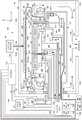
图1显示了根据一些实施方案的穿过用于半导体芯片制造的等离子体处理系统100的一部分的竖直截面图。1 shows a vertical cross-sectional view through a portion of aplasma processing system 100 for semiconductor chip fabrication, according to some embodiments.

图2显示了根据一些实施方案的通过用于半导体芯片制造的等离子体处理系统的竖直截面视图。2 shows a vertical cross-sectional view through a plasma processing system for semiconductor chip fabrication, according to some embodiments.

图3显示了根据一些实施方案的TES阻抗匹配系统的示例性电气示意图。3 shows an exemplary electrical schematic diagram of a TES impedance matching system, according to some embodiments.

图4是示出根据一些实施方案的TES阻抗匹配系统401中反射功率和电容器抽头位置之间的关系的曲线图。4 is a graph illustrating the relationship between reflected power and capacitor tap position in a TESimpedance matching system 401 according to some embodiments.

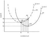
图5是显示根据一些实施方案的TES RF信号发生器403的反射功率与相位致动器位置的关系曲线图。FIG. 5 is a graph showing reflected power of a TESRF signal generator 403 versus phase actuator position, according to some embodiments.

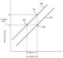
图6是显示根据一些实施方案的相位致动器位置与电容器抽头位置的关系曲线图。6 is a graph showing phase actuator position versus capacitor tap position, according to some embodiments.

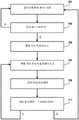
图7示出了根据本公开的实施方案,鉴于改变TES电压设定点以补偿边缘环磨损,优化TES匹配电容器抽头位置以最小化反射功率(即,伽马)的方法。7 illustrates a method of optimizing TES matching capacitor tap locations to minimize reflected power (ie, gamma) in view of changing the TES voltage set point to compensate for edge ring wear, according to an embodiment of the present disclosure.

图8示出了根据一些实施方案的图2的控制系统的示例性示意图。8 illustrates an exemplary schematic diagram of the control system of FIG. 2, according to some embodiments.

具体实施方式detailed description

在以下描述中,阐述了许多具体细节以便提供对本公开的实施方案的理解。然而,对于本领域的技术人员来说显而易见的是,可以在没有这些具体细节中的一些或全部的情况下实践本公开的实施方案。在其他情况下,没有详细描述众所周知的处理操作以避免不必要地使本公开难以理解。In the following description, numerous specific details are set forth in order to provide an understanding of embodiments of the present disclosure. It will be apparent, however, to one skilled in the art, that embodiments of the present disclosure may be practiced without some or all of these specific details. In other instances, well known process operations have not been described in detail in order not to unnecessarily obscure the present disclosure.

在用于半导体晶片制造的等离子蚀刻系统中,整个半导体晶片的蚀刻结果的空间变化可以通过径向蚀刻均匀性和方位角蚀刻均匀性来表征。径向蚀刻均匀性可以通过蚀刻速率的变化与半导体晶片上的径向位置的函数关系来表征,所述径向位置在半导体晶片上的给定方位角位置从半导体晶片的中心向外延伸到半导体晶片的边缘。并且,方位蚀刻均匀性可以通过蚀刻速率的变化与半导体晶片上的方位角位置的函数关系来表征,该方位角位置在半导体晶片上的给定径向位置处围绕半导体晶片的中心。在一些等离子体处理系统中,例如在本文描述的系统中,半导体晶片位于电极上,射频信号从该电极发出以在覆盖半导体晶片的等离子体产生区域内产生等离子体,等离子体具有受控制的特性以引起在半导体晶片上进行规定的蚀刻工艺。In plasma etching systems for semiconductor wafer fabrication, the spatial variation of etching results across a semiconductor wafer can be characterized by radial etch uniformity and azimuthal etch uniformity. Radial etch uniformity can be characterized by the change in etch rate as a function of radial position on the semiconductor wafer for a given azimuthal position on the semiconductor wafer extending from the center of the semiconductor wafer outward to the semiconductor edge of the wafer. Also, the azimuthal etch uniformity can be characterized by the change in etch rate as a function of the azimuthal position on the semiconductor wafer surrounding the center of the semiconductor wafer at a given radial position on the semiconductor wafer. In some plasma processing systems, such as the system described herein, a semiconductor wafer is positioned on electrodes from which radio frequency signals are emitted to generate a plasma in a plasma generation region covering the semiconductor wafer, the plasma having controlled characteristics to cause a prescribed etching process to be performed on the semiconductor wafer.

图1显示了根据一些实施方案的穿过用于半导体芯片制造的等离子体处理系统100的一部分的竖直截面图。等离子体处理系统100包括在一些实施方案中由铝形成的电极109。陶瓷层110形成在电极109的顶表面上。陶瓷层110被配置为在对晶片W执行等离子体处理操作期间接收和支撑晶片W。在一些实施方案中,陶瓷层110、电极109,以及相关的部件定义了静电卡盘(ESC)。1 shows a vertical cross-sectional view through a portion of aplasma processing system 100 for semiconductor chip fabrication, according to some embodiments.Plasma processing system 100 includeselectrode 109 formed of aluminum in some embodiments. Aceramic layer 110 is formed on the top surface of theelectrode 109 . Theceramic layer 110 is configured to receive and support the wafer W during a plasma processing operation performed thereon. In some embodiments,ceramic layer 110,electrode 109, and associated components define an electrostatic chuck (ESC).

第一射频信号发生器147(例如~60MHz)和第二射频信号发生器149(例如~400kHz)通过阻抗匹配系统143向电极109提供RF功率。向引入晶片上方的处理空间中的气态物质施加射频功率导致产生等离子体180以用于晶片处理,例如用于蚀刻。A first radio frequency signal generator 147 (eg, ~60 MHz) and a second radio frequency signal generator 149 (eg, ~400 kHz) provide RF power to theelectrode 109 through theimpedance matching system 143 . Application of RF power to the gaseous species introduced into the process volume above the wafer results in generation ofplasma 180 for wafer processing, eg, for etching.

边缘环167围绕陶瓷层110,并且被配置为便于等离子体鞘径向向外延伸超出晶片W的外围边缘,以改善晶片W外围附近的工艺结果。Theedge ring 167 surrounds theceramic layer 110 and is configured to facilitate the extension of the plasma sheath radially outward beyond the peripheral edge of the wafer W to improve process results near the periphery of the wafer W.

可调谐边缘鞘(TES)系统被实施为包括设置(嵌入)在耦合环161内的TES电极415。TES射频信号发生器403通过TES阻抗匹配系统401向TES电极415提供RF功率。TES系统能够控制晶片W周边附近的等离子体180的特性,例如控制等离子体鞘的特性、等离子体密度以及吸引或排斥离子。概括地说,通过将RF功率施加到TES电极415,TES系统能够调节晶片边缘处的等离子体以提高径向均匀性。A tunable edge sheath (TES) system is implemented to include aTES electrode 415 disposed (embedded) within thecoupling loop 161 . The TESRF signal generator 403 provides RF power to theTES electrode 415 through the TESimpedance matching system 401 . The TES system is capable of controlling the properties of theplasma 180 near the periphery of the wafer W, such as controlling the properties of the plasma sheath, plasma density, and attracting or repelling ions. In summary, by applying RF power to theTES electrode 415, the TES system can condition the plasma at the edge of the wafer to improve radial uniformity.

对于给定的工艺配方,设置工艺配方的参数,包括用于TES系统以提供径向均匀性的那些参数。例如,在所示实施方案中,对于具有起始厚度J1的边缘环167,由TES射频信号发生器403以第一电压V1提供RF功率,该第一电压V1被配置为调谐如S1所示的等离子体鞘,以在晶片W的边缘或周边区域具有高于晶片W的顶表面的高度H1。For a given process recipe, set the parameters of the process recipe, including those used in the TES system to provide radial uniformity. For example, in the illustrated embodiment, for anedge ring 167 having an initial thickness J1, RF power is provided by a TESRF signal generator 403 at a first voltage V1 configured to tune The plasma sheath to have a height H1 above the top surface of the wafer W at an edge or peripheral region of the wafer W.

然而,在等离子体处理期间,边缘环167被部分消耗或磨损,因此边缘环167的厚度在其寿命期间随着RF小时数和工艺周期的累积而逐渐减小。因此,例如,在多个RF小时的过程中,边缘环167的厚度可以从厚度J1减小到厚度J2。随着边缘环167的厚度减小,并且在处理期间随着电压V1的施加,等离子体鞘的水平也下降。例如,当边缘环167的厚度磨损到厚度J2时,等离子体鞘下降到如S2所示的水平,从而在晶片边缘处下降到晶片W的顶表面上方的高度H2。However, during plasma processing, theedge ring 167 is partially consumed or worn, so the thickness of theedge ring 167 gradually decreases over its lifetime as RF hours and process cycles accumulate. Thus, for example, the thickness ofedge ring 167 may decrease from thickness J1 to thickness J2 over the course of a number of RF hours. As the thickness of theedge ring 167 decreases, and as the voltage V1 is applied during processing, the level of the plasma sheath also decreases. For example, when the thickness ofedge ring 167 wears down to thickness J2, the plasma sheath drops to a level shown as S2, thereby dropping to a height H2 above the top surface of wafer W at the edge of the wafer.

边缘环厚度的这种减小和导致的在晶片边缘处等离子体鞘水平的改变导致边缘处的径向不均匀性。例如,晶片的边缘处与中心部分的蚀刻速率可能存在差异(蚀刻速率和蚀刻深度的不均匀性),以及边缘处可能存在特征轮廓倾斜(蚀刻方向的不均匀性)。This reduction in edge ring thickness and the resulting change in plasma sheath level at the wafer edge results in radial non-uniformity at the edge. For example, there may be a difference in etch rate at the edge of the wafer compared to the center portion (non-uniformity in etch rate and etch depth), and there may be feature profile slope at the edge (non-uniformity in etch direction).

因此,为了抵消边缘环磨损/消耗的影响,并且在边缘环厚度损失的情况下保持等离子体鞘的水平,可以将施加到TES电极415的电压增加到第二电压V2。在所示实施方案中,当TES射频信号发生器403施加电压V2(大于电压V1)并且边缘鞘厚度已经减小到厚度J2时,等离子体鞘恢复到参考S1处所示的厚度。即,即使边缘环167的厚度已经减小,等离子体鞘的水平也通过在TES系统中施加增加的电压而保持。Therefore, in order to counteract the effect of edge ring wear/wear and maintain the level of the plasma sheath in the event of loss of edge ring thickness, the voltage applied to theTES electrode 415 can be increased to the second voltage V2. In the illustrated embodiment, when the TESRF signal generator 403 applies voltage V2 (greater than voltage V1 ) and the edge sheath thickness has decreased to thickness J2, the plasma sheath returns to the thickness shown at reference S1. That is, even though the thickness of theedge ring 167 has been reduced, the level of the plasma sheath is maintained by applying increased voltage in the TES system.

然而,增加施加到TES电极415的电压会改变系统的阻抗,并导致射频功率的反射增加。为了最小化反射的射频功率,可以调整TES阻抗匹配系统401中的电容设置,如下文进一步详细讨论的。However, increasing the voltage applied to theTES electrode 415 changes the impedance of the system and results in increased reflection of RF power. To minimize reflected RF power, the capacitance settings in the TESimpedance matching system 401 may be adjusted, as discussed in further detail below.

注意,TES射频信号发生器403被配置为自动调整其产生的射频信号的相位,以匹配由射频信号发生器149(例如,在400kHz)产生的射频信号的相位。因此,当施加到TES电极415的电压增加时,TES射频信号发生器401会自动调整以保持与来自射频信号发生器149的射频信号的相位匹配。已经发现,在TES阻抗匹配系统中的对电容设置的调整(其使反射的RF功率最小化)是导致通过TES射频信号发生器403进行的相位调整(其自动发生)基本上返回到其用于原始电压(被增加以补偿边缘环磨损之前的第一电压)的原始相位调整量的对电容设置的调整。因此,可以利用相位调整量来优化TES阻抗匹配系统中的电容设置。Note that the TESRF signal generator 403 is configured to automatically adjust the phase of the RF signal it generates to match the phase of the RF signal generated by the RF signal generator 149 (eg, at 400 kHz). Therefore, as the voltage applied to theTES electrode 415 increases, the TESRF signal generator 401 automatically adjusts to maintain phase matching with the RF signal from theRF signal generator 149 . It has been found that adjustments to capacitance settings in the TES impedance matching system (which minimize reflected RF power) result in phase adjustments by the TES RF signal generator 403 (which occur automatically) essentially returning to the Adjustment of the capacitive setting by the raw phase adjustment of the raw voltage (increased to compensate for the first voltage before edge ring wear). Therefore, the amount of phase adjustment can be used to optimize the capacitance setting in the TES impedance matching system.

图2显示了根据一些实施方案的穿过用于半导体芯片制造的等离子体处理系统100的竖直截面图。系统100包括由壁101A、顶部构件101B和底部构件101C形成的室101。壁101A、顶部构件101B和底部构件101C共同形成室101内的内部区域103。底部构件101C包括排放端口105,来自等离子体处理操作的废气被引导通过该排放端口。在一些实施方案中,在操作期间,在排放端口105处施加吸力,例如通过涡轮泵或其他真空设备施加,以将工艺废气抽出室101的内部区域103。在一些实施方案中,室101由铝制成。然而,在多种实施方案中,室101可以基本上由提供足够机械强度、可接受的热性能并且与它所连接的以及它在室101内的等离子体处理操作期间所接触的其他材料化学相容的任何材料(例如不锈钢等)形成。室101的至少一个壁101A包括门107,半导体晶片W通过门107进出室101。在一些实施方案中,门107被配置为狭缝阀门。FIG. 2 shows a vertical cross-sectional view through aplasma processing system 100 for semiconductor chip fabrication, according to some embodiments. Thesystem 100 includes achamber 101 formed by awall 101A, atop member 101B, and abottom member 101C.Wall 101A,top member 101B, andbottom member 101C collectively form aninterior region 103 withinchamber 101 . Thebottom member 101C includes anexhaust port 105 through which exhaust gas from the plasma processing operation is directed. In some embodiments, during operation, suction is applied atexhaust port 105 , such as by a turbo pump or other vacuum device, to draw process exhaust gases out ofinterior region 103 ofchamber 101 . In some embodiments,chamber 101 is made of aluminum. However, in various embodiments, thechamber 101 may be substantially composed of other materials that provide sufficient mechanical strength, acceptable thermal performance, and are chemically compatible with it and with which it contacts during plasma processing operations within thechamber 101. Compatible with any material (such as stainless steel, etc.) formed. At least onewall 101A of thechamber 101 includes adoor 107 through which the semiconductor wafer W enters and exits thechamber 101 . In some embodiments,door 107 is configured as a slit valve.

在一些实施方案中,半导体晶片W是经历制造过程的半导体晶片。为了便于说明,以下将半导体晶片W称为晶片W。然而,应该理解的是,在多种实施方案中,晶片W基本上可以是经受基于等离子体的制造工艺的任何类型的衬底。例如,在一些实施方案中,如本文所指的晶片W可以是由硅、蓝宝石、GaN、GaAs或SiC或其他衬底材料形成的衬底,并且可以包括玻璃面板/衬底、金属箔、金属片、聚合物材料等等。此外,在多种实施方案中,如本文所指的晶片W可以在形式、形状和/或尺寸上有所不同。例如,在一些实施方案中,本文所指的晶片W可以对应于其上制造集成电路器件的圆形半导体晶片。在多种实施方案中,圆形晶片W可具有200mm(毫米)、300mm、450mm或其他尺寸的直径。此外,在一些实施方案中,本文所指的晶片W可以对应于非圆形衬底,例如用于平板显示器的矩形衬底等,以及其他形状。In some embodiments, semiconductor wafer W is a semiconductor wafer that has undergone a manufacturing process. For convenience of description, the semiconductor wafer W is referred to as a wafer W hereinafter. It should be understood, however, that in various embodiments, wafer W may be substantially any type of substrate subjected to a plasma-based fabrication process. For example, in some embodiments, a wafer W as referred to herein may be a substrate formed of silicon, sapphire, GaN, GaAs or SiC or other substrate materials, and may include glass panels/substrates, metal foils, metal sheets, polymer materials, etc. Furthermore, in various embodiments, wafers W as referred to herein may vary in form, shape and/or size. For example, in some embodiments, a wafer W referred to herein may correspond to a circular semiconductor wafer on which integrated circuit devices are fabricated. In various embodiments, the circular wafer W may have a diameter of 200 mm (millimeters), 300 mm, 450 mm, or other dimensions. Furthermore, in some embodiments, a wafer W referred to herein may correspond to non-circular substrates, such as rectangular substrates for flat panel displays, etc., among other shapes.

等离子处理系统100包括位于设施板111上的电极109。在一些实施方案中,电极109和设施板111由铝形成。然而,在其他实施方案中,电极109和设施板111可以由具有足够机械强度并且具有兼容的热和化学性能特性的另一种导电材料形成。陶瓷层110形成在电极109的顶表面上。在一些实施方案中,陶瓷层具有约1.25毫米(mm)的竖直厚度,如垂直于电极109的顶表面测量的竖直厚度。然而,在其他实施方案中,陶瓷层110可以具有大于或小于1.25mm的竖直厚度。陶瓷层110被配置为在对晶片W执行等离子体处理操作期间接收和支撑晶片W。在一些实施方案中,位于陶瓷层110径向外侧的电极190的顶表面和电极109的外围侧表面覆盖有陶瓷喷涂层。Plasma processing system 100 includeselectrodes 109 located onfacility plate 111 . In some embodiments,electrodes 109 andfacility plate 111 are formed from aluminum. However, in other embodiments, theelectrodes 109 and thefacility plate 111 may be formed from another electrically conductive material that has sufficient mechanical strength and has compatible thermal and chemical performance characteristics. Aceramic layer 110 is formed on the top surface of theelectrode 109 . In some embodiments, the ceramic layer has a vertical thickness of about 1.25 millimeters (mm), as measured perpendicular to the top surface of theelectrode 109 . However, in other embodiments, theceramic layer 110 may have a vertical thickness greater or less than 1.25 mm. Theceramic layer 110 is configured to receive and support the wafer W during a plasma processing operation performed thereon. In some embodiments, the top surface of the electrode 190 and the peripheral side surface of theelectrode 109 located radially outside theceramic layer 110 are covered with a ceramic sprayed layer.

陶瓷层110包括一个或多个夹持电极112的布置,其用于产生静电力以将晶片W保持在陶瓷层110的顶表面。在一些实施方案中,陶瓷层110包括两个以双极方式操作以向晶片W提供夹持力的夹持电极112。夹持电极112连接到直流(DC)电源117,该直流电源117产生受控的夹持电压以将晶片W保持在陶瓷层110的顶表面上。电线119A、119B连接在DC电源117和设施板111之间。电线/导体穿过设施板111和电极109以将电线119A、119B电气连接到夹持电极112上。DC电源117通过一个或多个信号导体121连接到控制系统120。Theceramic layer 110 includes an arrangement of one or more clamping electrodes 112 for generating an electrostatic force to hold the wafer W on the top surface of theceramic layer 110 . In some embodiments, theceramic layer 110 includes two clamping electrodes 112 that operate in a bipolar fashion to provide a clamping force to the wafer W. The clamping electrodes 112 are connected to a direct current (DC)power source 117 that generates a controlled clamping voltage to hold the wafer W on the top surface of theceramic layer 110 .Wires 119A, 119B are connected between theDC power source 117 and thefacility board 111 . Wires/conductors are passed through thefacility plate 111 and theelectrodes 109 to electrically connect thewires 119A, 119B to the clamping electrodes 112 .DC power source 117 is connected to controlsystem 120 through one ormore signal conductors 121 .

电极109还包括温度控制流体通道123的布置,温度控制流体流过温度控制流体通道以控制电极109的温度并进而控制晶片W的温度。温度控制流体通道123是管道连接(流体连接)到设施板111上的端口。温度控制流体供应和返回管线连接到设施板111上的这些端口和温度控制流体循环系统125,如箭头126所示。温度控制流体循环系统125包括温度控制流体供应源、温度控制流体泵和热交换器以及其他设备,以提供通过电极109的温度控制流体的受控流动,以获得并保持规定的晶片W温度。温度控制流体循环系统125通过一个或多个信号导体127连接到控制系统120。在多种实施方案中,可以使用各种类型的温度控制流体,例如水或制冷剂液体/气体。此外,在一些实施方案中,温度控制流体通道123被配置成能够对晶片W的温度进行空间(例如在晶片W上的二维(x和y)中)变化控制。Theelectrode 109 also includes an arrangement of temperature controlfluid channels 123 through which a temperature control fluid flows to control the temperature of theelectrode 109 and thus the temperature of the wafer W. The temperature controlfluid channel 123 is a port that is plumbed (fluidically connected) to thefacility plate 111 . The temperature control fluid supply and return lines are connected to these ports on thefacility plate 111 and to the temperature controlfluid circulation system 125 as indicated byarrows 126 . The temperature controlfluid circulation system 125 includes a temperature control fluid supply, a temperature control fluid pump and heat exchanger, and other equipment to provide a controlled flow of temperature control fluid through theelectrodes 109 to achieve and maintain a prescribed wafer W temperature. Temperature controlfluid circulation system 125 is connected to controlsystem 120 by one ormore signal conductors 127 . In various embodiments, various types of temperature control fluids may be used, such as water or refrigerant liquid/gas. Furthermore, in some embodiments, the temperaturecontrol fluid channel 123 is configured to enable spatially (eg, in two dimensions (x and y) on the wafer W) control of the temperature of the wafer W.

陶瓷层110还包括背面气体供应端口(未图示)的布置,这些端口与电极109内的相应背面气体供应通道流体连接。电极109内的背面气体供应通道通过电极109连接到电极109和设施板111之间的界面。一个或多个背面气体供应管线连接到设施板111上的端口和背面气体供应系统129,如箭头130所示。设施板111被配置为将来自一个或多个背面气体供应管线的背面气体供应到电极109内的背面气体供应通道。背面气体供应系统129包括背面气体供应源、质量流量控制器和流量控制阀以及其他设备,以通过陶瓷层110中的背面气体供应端口的布置来提供受控的背面气体流量。在一些实施方案中,背面气体供应系统129还包括一个或多个用于控制背面气体温度的部件。在一些实施方案中,背面气体是氦气。此外,在一些实施方案中,背面气体供应系统129可用于向陶瓷层110中的背面气体供应端口的布置供应清洁干燥空气(CDA)。背面气体供应系统129通过一个或多个信号导体131连接到控制系统120。Theceramic layer 110 also includes an arrangement of backside gas supply ports (not shown) that are in fluid connection with corresponding backside gas supply channels within theelectrode 109 . The backside gas supply channel within theelectrode 109 is connected through theelectrode 109 to the interface between theelectrode 109 and thefacility plate 111 . One or more back gas supply lines are connected to ports on thefacility plate 111 and to the backgas supply system 129 as indicated byarrow 130 . Thefacility plate 111 is configured to supply backside gas from one or more backside gas supply lines to backside gas supply channels within theelectrode 109 . The backsidegas supply system 129 includes backside gas supply sources, mass flow controllers and flow control valves, and other devices to provide controlled backside gas flow through the arrangement of backside gas supply ports in theceramic layer 110 . In some embodiments, the backsidegas supply system 129 also includes one or more components for controlling the temperature of the backside gas. In some embodiments, the backside gas is helium. Additionally, in some embodiments, the backsidegas supply system 129 may be used to supply clean dry air (CDA) to the arrangement of backside gas supply ports in theceramic layer 110 . Backsidegas supply system 129 is connected to controlsystem 120 by one ormore signal conductors 131 .

三个升降销132延伸穿过设施板111、电极109和陶瓷层110以提供晶片W相对于陶瓷层110的顶表面的竖直移动。在一些实施方案中,升降销132由连接到设施板111的相应机电和/或气动升降设备133控制。三个升降设备133通过一个或多个信号导体134连接到控制系统120。在一些实施方案中,三个升降销132定位成具有关于电极109/陶瓷层110的竖直中心线的大致相等的方位角间距,该竖直中心线垂直于陶瓷层110的顶表面延伸。应该理解,升降销132被升高以将晶片W接收放入室101并从室101中取出晶片W,参见图1B。此外,升降销132被降低以使得在晶片W的处理期间晶片W能搁置在陶瓷层110的顶表面上。Three lift pins 132 extend through thefacility plate 111 , theelectrodes 109 and theceramic layer 110 to provide vertical movement of the wafer W relative to the top surface of theceramic layer 110 . In some embodiments, lift pins 132 are controlled by corresponding electromechanical and/orpneumatic lift devices 133 connected tofacility plate 111 . Threelifting devices 133 are connected to controlsystem 120 by one ormore signal conductors 134 . In some embodiments, the threelift pins 132 are positioned with approximately equal azimuthal spacing about the vertical centerline of theelectrode 109 /ceramic layer 110 , which extends perpendicular to the top surface of theceramic layer 110 . It should be understood that the lift pins 132 are raised to receive the wafer W into and remove the wafer W from thechamber 101 , see FIG. 1B . Furthermore, the lift pins 132 are lowered so that the wafer W can rest on the top surface of theceramic layer 110 during the processing of the wafer W. Referring to FIG.

此外,在多种实施方案中,电极109、设施板111、陶瓷层110、夹持电极112、升降销132或与其相关联的基本上任何其他部件中的一者或多者可以被配备为包括一个或多个传感器,例如用于温度测量、电压测量和电流测量的传感器等。任何布置在电极109、设施板111、陶瓷层110、夹持电极112、升降销132或与其相关联的基本上任何其他部件内的传感器通过电线、光纤或通过无线连接而连接到控制系统120。Furthermore, in various embodiments, one or more of theelectrodes 109, thefacility plate 111, theceramic layer 110, the clamping electrodes 112, the lift pins 132, or substantially any other component associated therewith may be configured to include One or more sensors, such as sensors for temperature measurement, voltage measurement, current measurement, etc. Any sensors disposed withinelectrodes 109 ,facility plate 111 ,ceramic layer 110 , clamping electrodes 112 , lift pins 132 , or substantially any other component associated therewith are connected to controlsystem 120 by wire, fiber optics, or by wireless connection.

设施板111设置在陶瓷支撑件113的开口内,并由陶瓷支撑件113支撑。陶瓷支撑件113位于悬臂组件115的支撑表面114上。在一些实施方案中,陶瓷支撑件113具有大致环形形状,使得陶瓷支撑件113大致围绕设施板111的外径向周边,同时还提供支撑表面116,设施板111的底部外周表面搁置在该支撑表面116上。悬臂组件115延伸穿过室101的壁101A。在一些实施方案中,密封机构135设置在室101的壁101A内,悬臂组件115位于该密封机构135上以提供对室101的内部区域103的密封,同时还使悬臂组件115能够以受控方式沿z方向上下移动。Thefacility board 111 is disposed in the opening of theceramic supporter 113 and supported by theceramic supporter 113 . Aceramic support 113 rests on asupport surface 114 of acantilever assembly 115 . In some embodiments, theceramic support 113 has a generally annular shape such that theceramic support 113 generally surrounds the outer radial perimeter of thefacility plate 111 while also providing asupport surface 116 upon which the bottom peripheral surface of thefacility plate 111 rests. 116 on.Cantilever assembly 115 extends acrosswall 101A ofchamber 101 . In some embodiments, asealing mechanism 135 is disposed within thewall 101A of thechamber 101 on which thecantilever assembly 115 is positioned to provide a seal to theinterior region 103 of thechamber 101 while also enabling thecantilever assembly 115 to move in a controlled manner. Move up and down in the z direction.

悬臂组件115具有开放区域118,各种设备、电线、电缆和管道通过该开放区域118布线以支持系统100的操作。悬臂组件内的开放区域118暴露于室101外部的环境大气条件,例如空气成分、温度、压力和相对湿度。此外,射频信号供应杆137定位于悬臂组件115的内部。更具体地,射频信号供应杆137位于导电管139的内部,使得射频信号供应杆137与管139的内壁间隔开。射频信号供应杆137和管139的尺寸可以不同。在管139的内壁和射频信号供应杆137之间的管139内部的区域被沿着管139的全长的空气占据。在一些实施方案中,射频信号供应杆137的外径(Drod)和管139的内径(Dtube)被设定为满足关系ln(Dtube/Drod)>=e1Theboom assembly 115 has anopen area 118 through which various equipment, wires, cables, and conduits are routed to support the operation of thesystem 100 . Theopen area 118 within the cantilever assembly is exposed to ambient atmospheric conditions outside thechamber 101, such as air composition, temperature, pressure and relative humidity. In addition, an RFsignal supply rod 137 is positioned inside theboom assembly 115 . More specifically, the radio frequencysignal supply rod 137 is located inside theconductive tube 139 such that the radio frequencysignal supply rod 137 is spaced apart from the inner wall of thetube 139 . The radio frequencysignal supply rod 137 and thetube 139 may vary in size. The area inside thetube 139 between the inner wall of thetube 139 and the radio frequencysignal supply rod 137 is occupied by air along the entire length of thetube 139 . In some embodiments, the outer diameter (Drod ) of the radio frequencysignal supply rod 137 and the inner diameter (Dtube ) of thetube 139 are set to satisfy the relationship ln(Dtube /Drod )>=e1 .

在一些实施方案中,射频信号供应杆137在管139内基本居中,使得在射频信号供应杆137和管139的内壁之间存在沿管139的长度方向存在基本均匀径向厚度的空气。然而,在一些实施方案中,射频信号供应杆137不在管139内居中,而是在射频信号供应杆137和管139的内壁之间沿着管139的长度的所有位置处都存在管139内的气隙。射频信号供应杆137的输送端通过电气和物理方式连接到射频信号供应轴141的下端。在一些实施方案中,射频信号供应杆的输送端137用螺栓栓接到射频信号供应轴141的下端。射频信号供应轴141的上端通过电气和物理方式连接到设施板111的底部。在一些实施方案中,射频信号供应轴141的上端用螺栓栓接到设施板111的底部。在一些实施方案中,射频信号供应杆137和射频信号供应轴141均由铜形成。在一些实施方案中,射频信号供应杆137由铜、铝或阳极氧化铝形成。在一些实施方案中,射频信号供应轴141由铜、铝或阳极氧化铝形成。在其他实施方案中,射频信号供应杆137和/或射频信号供应轴141由提供射频电信号传输的另一种导电材料形成。在一些实施方案中,射频信号供应杆137和/或射频信号供应轴141涂有提供射频电信号传输的导电材料(例如银或其他导电材料)。此外,在一些实施方案中,射频信号供应杆137是实心杆。然而,在其他实施方案中,射频信号供应杆137是管。另外,应当理解,射频信号供应杆137和射频信号供应轴141之间的连接部周围的区域140被空气占据。In some embodiments, the RFsignal supply rod 137 is substantially centered within thetube 139 such that there is a substantially uniform radial thickness of air along the length of thetube 139 between the RFsignal supply rod 137 and the inner wall of thetube 139 . However, in some embodiments, the radio frequencysignal supply rod 137 is not centered within thetube 139, but there is a gap within thetube 139 at all locations along the length of thetube 139 between the radio frequencysignal supply rod 137 and the inner wall of thetube 139. air gap. The delivery end of the radio frequencysignal supply rod 137 is electrically and physically connected to the lower end of the radio frequencysignal supply shaft 141 . In some embodiments, thedelivery end 137 of the radio frequency signal supply rod is bolted to the lower end of the radio frequencysignal supply shaft 141 . The upper end of the radio frequencysignal supply shaft 141 is electrically and physically connected to the bottom of thefacility board 111 . In some embodiments, the upper end of the RFsignal supply shaft 141 is bolted to the bottom of thefacility plate 111 . In some embodiments, both the RFsignal supply rod 137 and the RFsignal supply shaft 141 are formed of copper. In some embodiments, the RFsignal supply rod 137 is formed of copper, aluminum, or anodized aluminum. In some embodiments, the RFsignal supply shaft 141 is formed from copper, aluminum, or anodized aluminum. In other embodiments, the RFsignal supply rod 137 and/or the RFsignal supply shaft 141 are formed of another conductive material that provides RF electrical signal transmission. In some embodiments, the RFsignal supply rod 137 and/or the RFsignal supply shaft 141 is coated with a conductive material (eg, silver or other conductive material) that provides RF electrical signal transmission. Additionally, in some embodiments, the radio frequencysignal supply rod 137 is a solid rod. However, in other embodiments, the radio frequencysignal supply rod 137 is a tube. In addition, it should be understood that thearea 140 around the connection between the radio frequencysignal supply rod 137 and the radio frequencysignal supply shaft 141 is occupied by air.

射频信号供应杆137的供应端通过电气和物理方式连接到阻抗匹配系统143。阻抗匹配系统143连接到第一射频信号发生器147和第二射频信号发生器149。阻抗匹配系统143还通过一个或多个信号导体144连接到控制系统120。第一射频信号发生器147还通过一个或多个信号导体148连接到控制系统120。第二射频信号发生器149也通过一个或多个信号导体150连接到控制系统120。阻抗匹配系统143包括电感器和电容器的布置,电感器和电容器的尺寸和连接被设置为提供阻抗匹配,使得射频功率可以沿着射频信号供应杆137、沿射频信号供应轴141传输,通过设施板111,通过电极109,并进入陶瓷层110上方的等离子体处理区域182。在一些实施方案中,第一射频信号发生器147是高频射频信号发生器,而第二射频信号发生器149是低频射频信号发生器。在一些实施方案中,第一射频信号发生器147产生在从约50兆赫(MHz)延伸至约70MHz的范围内,或在从约54MHz至约63MHz延伸的范围内,或在约60MHz的射频信号。在一些实施方案中,第一射频信号发生器147提供在从约5千瓦(kW)延伸至约25kW的范围内,或在从约10kW延伸至约20kW的范围内,或在从约15kW延伸至约20kW的范围内,或约10kW,或约16kW的射频功率。在一些实施方案中,第二射频信号发生器149产生在从约50千赫兹(kHz)延伸至约500kHz的范围内,或在从约330kHz延伸至约440kHz的范围内,或在约400kHz的射频信号。在一些实施方案中,第二射频信号发生器149提供在从约15kW延伸至约100kW的范围内、或在从约30kW延伸至约50kW的范围内、或约34kW、或约50kW的射频功率。在一示例性实施方案中,第一射频信号发生器147被设置为产生具有约60MHz的频率的射频信号,并且第二射频信号发生器149被设置为产生具有约400kHz的频率的射频信号。The supply end of the radio frequencysignal supply rod 137 is electrically and physically connected to theimpedance matching system 143 . Theimpedance matching system 143 is connected to a first radiofrequency signal generator 147 and a second radiofrequency signal generator 149 .Impedance matching system 143 is also connected to controlsystem 120 through one ormore signal conductors 144 . The first radiofrequency signal generator 147 is also connected to thecontrol system 120 via one ormore signal conductors 148 . A second radiofrequency signal generator 149 is also connected to thecontrol system 120 via one ormore signal conductors 150 .Impedance matching system 143 includes an arrangement of inductors and capacitors sized and connected to provide impedance matching so that RF power can be transmitted along RFsignal supply bar 137, along RFsignal supply axis 141, through thefacility plate 111 , through theelectrode 109 and into theplasma treatment region 182 above theceramic layer 110 . In some embodiments, the first radiofrequency signal generator 147 is a high frequency radio frequency signal generator and the second radiofrequency signal generator 149 is a low frequency radio frequency signal generator. In some embodiments, the first radiofrequency signal generator 147 generates a radio frequency signal in a range extending from about 50 megahertz (MHz) to about 70 MHz, or in a range extending from about 54 MHz to about 63 MHz, or at about 60 MHz . In some embodiments, the first radiofrequency signal generator 147 is provided in a range extending from about 5 kilowatts (kW) to about 25 kW, or in a range extending from about 10 kW to about 20 kW, or in a range extending from about 15 kW to about 25 kW. In the range of about 20kW, or about 10kW, or about 16kW of RF power. In some embodiments, the second radiofrequency signal generator 149 generates a radio frequency in the range extending from about 50 kilohertz (kHz) to about 500 kHz, or in the range extending from about 330 kHz to about 440 kHz, or at about 400 kHz. Signal. In some embodiments, the secondRF signal generator 149 provides RF power in a range extending from about 15 kW to about 100 kW, or in a range extending from about 30 kW to about 50 kW, or about 34 kW, or about 50 kW. In an exemplary embodiment, the first radiofrequency signal generator 147 is configured to generate a radio frequency signal having a frequency of about 60 MHz, and the second radiofrequency signal generator 149 is configured to generate a radio frequency signal having a frequency of about 400 kHz.

耦合环161被配置和定位成围绕电极109的外径向周边延伸。在一些实施方案中,耦合环161由陶瓷材料形成。石英环163被配置和定位成围绕耦合环161和陶瓷支撑件113两者的外径向周边延伸。在一些实施方案中,耦合环161和石英环163被配置成当石英环163围绕耦合环161和陶瓷支撑件113定位时具有基本对齐的顶表面。此外,在一些实施方案中,耦合环161和石英环163的基本对齐的顶表面与电极109的顶表面基本对齐,所述顶表面存在于陶瓷层110的径向周边之外。此外,在一些实施方案中,盖环165被配置和定位成围绕石英环163的顶表面的径向外周边延伸。在一些实施方案中,盖环165由石英形成。在一些实施方案中,盖环165被配置为在石英环163的顶表面上方竖直延伸。以这种方式,盖环165提供让边缘环167位于其中的外围边界。Thecoupling ring 161 is configured and positioned to extend circumferentially around the outer diameter of theelectrode 109 . In some embodiments,coupling ring 161 is formed from a ceramic material.Quartz ring 163 is configured and positioned to extend circumferentially around the outer diameter of bothcoupling ring 161 andceramic support 113 . In some embodiments,coupling ring 161 andquartz ring 163 are configured to have substantially aligned top surfaces whenquartz ring 163 is positioned aboutcoupling ring 161 andceramic support 113 . Furthermore, in some embodiments, the substantially aligned top surfaces ofcoupling ring 161 andquartz ring 163 are substantially aligned with the top surface ofelectrode 109 that exists outside the radial perimeter ofceramic layer 110 . Additionally, in some embodiments,cover ring 165 is configured and positioned to extend around the radially outer perimeter of the top surface ofquartz ring 163 . In some embodiments,cover ring 165 is formed of quartz. In some embodiments,cover ring 165 is configured to extend vertically above the top surface ofquartz ring 163 . In this manner,cover ring 165 provides a peripheral boundary within whichedge ring 167 resides.

边缘环167被配置为便于等离子体鞘径向向外延伸超出晶片W的外围边缘,以改善晶片W外围附近的处理结果。在多种实施方案中,边缘环167由导电材料,例如晶体硅、硅多晶体(多晶硅)、掺硼单晶硅、氧化铝、石英、氮化铝、氮化硅、碳化硅或氧化铝层顶部的碳化硅层,或硅合金或其组合,以及其他材料形成。应当理解,边缘环167形成为环状结构,例如圆环结构。边缘环167可以执行许多功能,包括保护边缘环167下面的部件不被等离子体处理区域182内形成的等离子体180的离子损坏。此外,边缘环167提高了晶片W的外围区域处和沿着该外围区域的等离子体180的均匀性。Theedge ring 167 is configured to facilitate the extension of the plasma sheath radially outward beyond the peripheral edge of the wafer W to improve processing results near the periphery of the wafer W. In various embodiments,edge ring 167 is made of a conductive material such as crystalline silicon, silicon polycrystalline (polysilicon), boron-doped monocrystalline silicon, aluminum oxide, quartz, aluminum nitride, silicon nitride, silicon carbide, or an aluminum oxide layer. The top layer of silicon carbide, or silicon alloys or combinations thereof, and other materials are formed. It should be understood that theedge ring 167 is formed as an annular structure, such as a circular ring structure.Edge ring 167 may perform a number of functions, including protecting components beneathedge ring 167 from damage by ions ofplasma 180 formed withinplasma processing region 182 . Furthermore, theedge ring 167 improves the uniformity of theplasma 180 at and along the peripheral region of the wafer W. Referring to FIG.

固定外支撑凸缘169附接到悬臂组件115上。固定外支撑凸缘169被构造成围绕陶瓷支撑件113的外竖直侧表面、围绕石英环163的外竖直侧表面以及围绕盖环165的下部外竖直侧表面延伸。固定外支撑凸缘169具有外接陶瓷支撑件113、石英环163和盖环165的组件的环形形状。固定外支撑凸缘169具有包括竖直部分和水平部分的L形竖直截面。固定外支撑凸缘169的L形横截面的竖直部分具有内竖直表面,该内竖直表面抵靠陶瓷支撑件113的外竖直侧表面,并抵靠石英环163的外竖直侧表面,且抵靠在盖环165的下部外竖直侧表面定位。在一些实施方案中,固定外支撑凸缘169的L形横截面的竖直部分在陶瓷支撑件113的整个竖直侧表面、石英环163的整个外竖直侧表面以及盖环165的下部外竖直侧表面上延伸。在一些实施方案中,盖环165在固定外支撑凸缘169的L形横截面的竖直部分的顶表面上方径向向外延伸。并且,在一些实施方案中,盖环165的上部外竖直侧表面(位于固定外支撑凸缘169的L形横截面的竖直部分的顶表面上方)与固定外支撑凸缘169的L形横截面的竖直部分的外竖直表面基本竖直对齐。固定外支撑凸缘169的L形横截面的水平部分定位并固定在悬臂组件115的支撑表面114上。固定外支撑凸缘169由导电材料制成。在一些实施方案中,固定外支撑凸缘169由铝或阳极氧化铝形成。然而,在其他实施方案中,固定外支撑凸缘169可以由另一种导电材料形成,例如由铜或不锈钢形成。在一些实施方案中,固定外支撑凸缘169的L形横截面的水平部分用螺栓栓接到悬臂组件115的支撑表面114上。A fixedouter support flange 169 is attached to theboom assembly 115 . The fixedouter support flange 169 is configured to extend around the outer vertical side surface of theceramic support 113 , around the outer vertical side surface of thequartz ring 163 , and around the lower outer vertical side surface of thecover ring 165 . The fixedouter support flange 169 has an annular shape circumscribing the assembly of theceramic support 113 , thequartz ring 163 and thecover ring 165 . The fixedouter support flange 169 has an L-shaped vertical section including a vertical portion and a horizontal portion. The vertical portion of the L-shaped cross-section of the fixedouter support flange 169 has an inner vertical surface which abuts against the outer vertical side surface of theceramic support 113 and against the outer vertical side of thequartz ring 163 surface, and is positioned against the lower outer vertical side surface ofcover ring 165 . In some embodiments, the vertical portion of the L-shaped cross-section of the fixedouter support flange 169 is fixed over the entire vertical side surface of theceramic support 113, the entire outer vertical side surface of thequartz ring 163, and the lower outer surface of thecover ring 165. extending on the vertical side surface. In some embodiments, thecover ring 165 extends radially outward over the top surface of the vertical portion of the L-shaped cross-section of the fixedouter support flange 169 . Also, in some embodiments, the upper outer vertical side surface of the cover ring 165 (located above the top surface of the vertical portion of the L-shaped cross-section of the fixed outer support flange 169 ) is aligned with the L-shaped portion of the fixedouter support flange 169. The outer vertical surfaces of the vertical portions of the cross-section are substantially vertically aligned. The horizontal portion of the L-shaped cross-section of the stationaryouter support flange 169 is positioned and secured on thesupport surface 114 of theboom assembly 115 . The fixedouter support flange 169 is made of conductive material. In some embodiments, fixedouter support flange 169 is formed from aluminum or anodized aluminum. However, in other embodiments, fixedouter support flange 169 may be formed from another electrically conductive material, such as copper or stainless steel. In some embodiments, the horizontal portion of the L-shaped cross-section of the stationaryouter support flange 169 is bolted to thesupport surface 114 of theboom assembly 115 .

铰接式外支撑凸缘171被配置和定位为围绕固定外支撑凸缘169的L形横截面的竖直部分的外竖直表面169D延伸,并且围绕盖环165的上部外竖直侧表面延伸。铰接式外支撑凸缘171具有环形形状,其外接固定外支撑凸缘169的L形竖直截面的竖直部分和盖环165的上部外竖直侧表面。铰接式外支撑凸缘171具有L形竖直截面,其包括竖直部分和水平部分。铰接式外支撑凸缘171的L形横截面的竖直部分具有内竖直表面,该内竖直表面位于靠近固定外支撑凸缘169的L型横截面的竖直部分的外竖直侧表面和盖环165的上部外竖直侧表面两者定位并与其间隔开。这样,铰接式外支撑凸缘171可沿固定外支撑凸缘169的L形竖直截面的竖直部分和盖环165的上部外竖直侧表面两者在竖直方向(z方向)上移动。铰接式外支撑凸缘171由导电材料制成。在一些实施方案中,铰接式外支撑凸缘171由铝或阳极氧化铝形成。然而,在其他实施方案中,铰接式外支撑凸缘171可以由另一种导电材料形成,例如由铜或不锈钢形成。The hingedouter support flange 171 is configured and positioned to extend around the outer vertical surface 169D of the vertical portion of the L-shaped cross-section of the fixedouter support flange 169 and around the upper outer vertical side surface of thecover ring 165 . The hingedouter support flange 171 has an annular shape that circumscribes the vertical portion of the L-shaped vertical section of the fixedouter support flange 169 and the upper outer vertical side surface of thecover ring 165 . The hingedouter support flange 171 has an L-shaped vertical section including a vertical portion and a horizontal portion. The vertical portion of the L-shaped cross-section of the hingedouter support flange 171 has an inner vertical surface located adjacent to the outer vertical side surface of the vertical portion of the L-shaped cross-section of the fixedouter support flange 169 Both are positioned and spaced apart from the upper outer vertical side surface ofcover ring 165 . In this way, the hingedouter support flange 171 can move in the vertical direction (z direction) along both the vertical portion of the L-shaped vertical section of the fixedouter support flange 169 and the upper outer vertical side surface of thecover ring 165. . The hingedouter support flange 171 is made of electrically conductive material. In some embodiments, the hingedouter support flange 171 is formed from aluminum or anodized aluminum. However, in other embodiments, the hingedouter support flange 171 may be formed from another electrically conductive material, such as copper or stainless steel.

多个导电带173连接在铰接式外支撑凸缘171和固定外支撑凸缘169之间,围绕铰接式外支撑凸缘171和固定外支撑凸缘169的外径向周边。在示例性实施方案中,导电带173被示为具有“向外”配置,其中导电带173向外弯曲远离固定外支撑凸缘169。在一些实施方案中,导电带173由不锈钢形成。然而,在其他实施方案中,导电带173可以由另一种导电材料形成,例如由铝或铜等制成。A plurality ofconductive straps 173 are connected between the hingedouter support flange 171 and the fixedouter support flange 169 around the outer radial peripheries of the hingedouter support flange 171 and the fixedouter support flange 169 . In the exemplary embodiment, theconductive strap 173 is shown as having an “outward” configuration in which theconductive strap 173 is bent outwardly away from the fixedouter support flange 169 . In some embodiments, theconductive strip 173 is formed from stainless steel. However, in other embodiments, theconductive strap 173 may be formed from another conductive material, such as aluminum or copper, or the like.

在一些实施方案中,四十八(48)个导电带173以基本等间距的方式分布在铰接式外支撑凸缘171和固定外支撑凸缘169之间的外径向周边。然而,应该理解的是,导电带173的数量可以在不同的实施方案中变化。在一些实施方案中,导电带173的数量在从约24延伸至约80的范围内,或在从约36延伸至约60的范围内,或在从约40延伸至约56的范围内。在一些实施方案中,导电带173的数量小于24。在一些实施方案中,导电带173的数量大于80。因为导电带173的数量对于在等离子体处理区域182的周边周围的射频信号的接地返回路径有影响,因此导电带173的数量可以对整个晶片W上的处理结果的均匀性产生影响。此外,导电带173的尺寸可以在不同的实施方案中变化。In some embodiments, forty-eight (48)conductive straps 173 are distributed in a substantially equally spaced manner on the outer radial perimeter between hingedouter support flange 171 and fixedouter support flange 169 . However, it should be understood that the number ofconductive strips 173 may vary in different embodiments. In some embodiments, the number ofconductive strips 173 ranges from about 24 to about 80, or from about 36 to about 60, or from about 40 to about 56. In some embodiments, the number ofconductive strips 173 is less than twenty-four. In some embodiments, the number ofconductive strips 173 is greater than eighty. Because the number ofconductive straps 173 has an effect on the ground return path of radio frequency signals around the perimeter of theplasma processing region 182 , the amount ofconductive straps 173 may have an impact on the uniformity of process results across the wafer W. Furthermore, the dimensions of theconductive strip 173 may vary in different embodiments.

在一些实施方案中,导电带173通过经由将夹持环175固定到固定外支撑凸缘169的L形横截面的水平部分的顶表面所施加的夹持力连接到固定外支撑凸缘169。在一些实施方案中,夹持环175用螺栓栓接到固定外支撑凸缘169。在一些实施方案中,将夹持环175固定到固定外支撑凸缘169的螺栓定位在导电带173之间的位置。然而,在一些实施方案中,将夹持环175固定到固定外支撑凸缘169的一个或多个螺栓可以定位成延伸穿过导电带173。在一些实施方案中,夹持环175由与固定外支撑凸缘169相同的材料制成。然而,在其他实施方案中,夹持环175和固定外支撑凸缘169可以由不同材料形成。In some embodiments, theconductive strap 173 is connected to the fixedouter support flange 169 by clamping force applied via theclamping ring 175 secured to the top surface of the horizontal portion of the L-shaped cross-section of the fixedouter support flange 169 . In some embodiments, theclamping ring 175 is bolted to the stationaryouter support flange 169 . In some embodiments, the bolts securing theclamping ring 175 to the securingouter support flange 169 are positioned between the conductive strips 173 . However, in some embodiments, one or more bolts that secure theclamping ring 175 to the fixedouter support flange 169 may be positioned to extend through theconductive strap 173 . In some embodiments, theclamping ring 175 is made of the same material as the fixedouter support flange 169 . However, in other embodiments, theclamping ring 175 and the stationaryouter support flange 169 may be formed of different materials.

在一些实施方案中,导电带173通过经由将夹持环177固定到铰接式外支撑凸缘171的L形横截面的水平部分的底表面所施加的夹持力连接到铰接式外支撑凸缘171。替代地,在一些实施方案中,多个导电带173中的每一个的第一端部分通过夹持环177连接到铰接式外支撑凸缘171的水平部分的上表面。在一些实施方案中,夹持环177用螺栓栓接到铰接式外支撑凸缘171。在一些实施方案中,将夹持环177固定到铰接式外支撑凸缘171的螺栓定位在位于导电带173之间的位置。然而,在一些实施方案中,将夹持环177固定到铰接式外支撑凸缘17上的一个或多个螺栓可以定位成延伸穿过导电带173。在一些实施方案中,夹持环177由与铰接式外支撑凸缘171相同的材料形成。然而,在其他实施方案中,夹持环177和铰接式外支撑凸缘171可以由不同的材料形成。In some embodiments, theconductive strap 173 is connected to the hinged outer support flange by clamping force applied via securing theclamping ring 177 to the bottom surface of the horizontal portion of the L-shaped cross-section of the hingedouter support flange 171 171. Alternatively, in some embodiments, a first end portion of each of the plurality ofconductive straps 173 is connected to the upper surface of the horizontal portion of the hingedouter support flange 171 by aclamping ring 177 . In some embodiments, theclamping ring 177 is bolted to the hingedouter support flange 171 . In some embodiments, the bolts that secure theclamping ring 177 to the hingedouter support flange 171 are positioned between theconductive straps 173 . However, in some embodiments, one or more bolts securing theclamping ring 177 to the hinged outer support flange 17 may be positioned to extend through theconductive strap 173 . In some embodiments, theclamping ring 177 is formed from the same material as the hingedouter support flange 171 . However, in other embodiments, theclamp ring 177 and the hingedouter support flange 171 may be formed of different materials.

一组支撑杆201围绕悬臂组件115定位,以竖直延伸穿过固定外支撑凸缘169的L形横截面的水平部分169B。支撑杆201的上端被构造成与铰接式外支撑凸缘171的L形横截面的水平部分的底表面接合。在一些实施方案中,每个支撑杆201的下端与阻力机构203接合。阻力机构203被配置为向相应的支撑杆201提供向上的力,该向上的力将抵抗支撑杆201的向下运动,同时允许支撑杆201的一些向下运动。在一些实施方案中,阻力机构203包括弹簧以向对应的支撑杆201提供向上的力。在一些实施方案中,阻力机构203包括具有足够弹簧常数的材料(例如弹簧和/或橡胶)以向对应的支撑杆201提供向上的力。应该理解的是,当铰接式外支撑凸缘171向下移动以接合支撑杆201的组时,支撑杆201的组和对应的阻力机构203向铰接式外支撑凸缘171提供向上的力。在一些实施方案中,支撑杆201的组包括三个支撑杆201和相应的阻力机构203。在一些实施方案中,支撑杆201被定位为相对于电极109的竖直中心线具有基本上相等的方位角间距。然而,在其他实施方案中,支撑杆201被定位成相对于电极109的竖直中心线具有不相等的方位角间距。此外,在一些实施方案中,提供了多于三个的支撑杆201和相应的阻力机构203以支撑铰接式外支撑凸缘171。A set ofsupport rods 201 are positioned about theboom assembly 115 to extend vertically across the horizontal portion 169B of the L-shaped cross-section of the fixedouter support flange 169 . The upper end of thesupport rod 201 is configured to engage the bottom surface of the horizontal portion of the L-shaped cross-section of the hingedouter support flange 171 . In some embodiments, the lower end of eachsupport rod 201 is engaged with aresistance mechanism 203 . Theresistance mechanism 203 is configured to provide an upward force to thecorresponding support rod 201 that will resist downward movement of thesupport rod 201 while allowing some downward movement of thesupport rod 201 . In some embodiments, theresistance mechanism 203 includes a spring to provide an upward force to thecorresponding support rod 201 . In some embodiments, theresistance mechanism 203 includes a material (eg, spring and/or rubber) with sufficient spring constant to provide an upward force to thecorresponding support rod 201 . It should be appreciated that the set ofsupport rods 201 andcorresponding resistance mechanisms 203 provide an upward force to the hingedouter support flange 171 as the hingedouter support flange 171 moves downwardly to engage the set ofsupport rods 201 . In some embodiments, a set ofsupport rods 201 includes threesupport rods 201 andcorresponding resistance mechanisms 203 . In some embodiments, thesupport rods 201 are positioned with substantially equal azimuthal spacing relative to the vertical centerline of theelectrodes 109 . However, in other embodiments, thesupport rods 201 are positioned with unequal azimuthal spacing relative to the vertical centerline of theelectrodes 109 . Additionally, in some embodiments, more than threesupport rods 201 andcorresponding resistance mechanisms 203 are provided to support the hingedouter support flange 171 .

继续参考图2,等离子体处理系统100还包括定位在电极109上方的C形护罩构件185。C形护罩构件185被配置为与铰接式外支撑凸缘171对接。具体而言,密封件179设置在铰接式外支撑凸缘171的L形横截面的水平部分的顶表面上,使得当铰接式外支撑凸缘171朝C形护罩构件185向上移动时,密封件179与C形护罩构件185接合。在一些实施方案中,密封件179是导电的以帮助形成在C形护罩构件185和铰接式外支撑凸缘171之间的导电。在一些实施方案中,C形护罩构件185由多晶硅形成。然而,在其他实施方案中,C形护罩构件185由与将在等离子体处理区域182中形成的工艺化学兼容并且具有足够机械强度的另一种类型的导电材料形成。With continued reference to FIG. 2 ,plasma processing system 100 also includes a C-shapedshield member 185 positioned overelectrode 109 . The C-shapedshroud member 185 is configured to interface with the hingedouter support flange 171 . Specifically, aseal 179 is provided on the top surface of the horizontal portion of the L-shaped cross-section of the hingedouter support flange 171 such that when the hingedouter support flange 171 moves upward toward the C-shapedshield member 185, the seal Thepiece 179 engages the C-shapedshield member 185 . In some embodiments, theseal 179 is electrically conductive to help create electrical conductivity between the C-shapedshroud member 185 and the hingedouter support flange 171 . In some embodiments, the C-shapedshroud member 185 is formed of polysilicon. However, in other embodiments, the C-shapedshield member 185 is formed from another type of conductive material that is chemically compatible with the process to be formed in theplasma processing region 182 and has sufficient mechanical strength.

C形护罩被配置为围绕等离子体处理区域182延伸,并且提供径向延伸到C形护罩构件185内限定的区域中的等离子体处理区域182体积。C形护罩构件185包括下壁185A、外竖直壁185B和上壁185C。在一些实施方案中,C形护罩构件185的外竖直壁185B和上壁185C是实心的非穿孔构件,并且C形护罩构件185的下壁185A包括多个通风口186,来自等离子体处理区域182内的工艺气体通过这些通风口流动。在一些实施方案中,节流构件196设置在C形护罩构件185的通风口186下方以控制通过通风口186的工艺气体的流动。更具体地,在一些实施方案中,节流构件196被配置为在z方向上相对于C形护罩构件185竖直上下移动以控制工艺气体通过通风口186的流动。在一些实施方案中,节流构件196被配置为与通风口186接合和/或进入通风口186。The C-shroud is configured to extend around theplasma processing region 182 and provides a volume of theplasma processing region 182 that extends radially into a region defined within the C-shroud member 185 . The C-shapedshield member 185 includes alower wall 185A, an outervertical wall 185B, and anupper wall 185C. In some embodiments, the outervertical wall 185B and theupper wall 185C of the C-shield member 185 are solid non-perforated members, and thelower wall 185A of the C-shield member 185 includes a plurality ofvents 186 from the plasma Process gases withinprocessing region 182 flow through these vents. In some embodiments, athrottle member 196 is disposed below thevent 186 of the C-shapedshroud member 185 to control the flow of process gas through thevent 186 . More specifically, in some embodiments,throttle member 196 is configured to move vertically up and down in the z-direction relative to C-shapedshroud member 185 to control the flow of process gas throughvent 186 . In some embodiments, thethrottle member 196 is configured to engage with and/or enter thevent 186 .

C形护罩构件185的上壁185C被构造成支撑上电极187A/187B。在一些实施方案中,上电极187A/187B包括内部上电极187A和外部上电极187B。替代地,在一些实施方案中,存在内部上电极187A并且不存在外部上电极187B,内部上电极187A径向延伸以覆盖本来由外部上电极187B占据的位置。在一些实施方案中,内部上电极187A由单晶硅形成,并且外部上电极187B由多晶硅形成。然而,在其他实施方案中,内部上电极187A和外部上电极187B可以由在结构上、化学上、电气上和机械上与待在等离子体处理区域182内执行的工艺兼容的其他材料形成。内部上电极187A包括多个直通端口197,这些直通端口197被定义为延伸穿过内部上电极187A的整个竖直厚度的孔。直通端口197相对于x-y平面分布在整个内部上电极187A上,以提供工艺气体从上电极187A/187B上方的增压区域188到上电极187A/187B下方的等离子体处理区域182的流动。Theupper wall 185C of the C-shapedshield member 185 is configured to support theupper electrodes 187A/187B. In some embodiments,upper electrodes 187A/187B include innerupper electrodes 187A and outerupper electrodes 187B. Alternatively, in some embodiments, where innerupper electrode 187A is present and outerupper electrode 187B is absent, innerupper electrode 187A extends radially to cover the position otherwise occupied by outerupper electrode 187B. In some embodiments, the upperinner electrode 187A is formed of monocrystalline silicon and the upperouter electrode 187B is formed of polycrystalline silicon. However, in other embodiments, innerupper electrode 187A and outerupper electrode 187B may be formed of other materials that are structurally, chemically, electrically, and mechanically compatible with the processes to be performed withinplasma processing region 182 . The upperinner electrode 187A includes a plurality of through-ports 197 defined as holes extending through the entire vertical thickness of the upperinner electrode 187A. Through-ports 197 are distributed throughout the innerupper electrode 187A with respect to the x-y plane to provide flow of process gases from theplenum region 188 above theupper electrodes 187A/187B to theplasma processing region 182 below theupper electrodes 187A/187B.

应当理解,对于不同的实施方案,可以以不同的方式配置在整个内部上电极187A上的直通端口197的分布。例如,内部上电极187A内的直通端口197的总数和/或内部上电极187A内的直通端口197的空间分布可以在不同实施方案之间变化。此外,直通端口197的直径可以在不同实施方案之间变化。通常,将直通端口197的直径减小到足够小的尺寸以防止等离子体180从等离子体处理区域182侵入直通端口197是有意义的。在一些实施方案中,随着直通端口197的直径减小,内部上电极187A内的直通端口197的总数增加以维持从工艺气体增压区域188通过内部上电极187A到达等离子体处理区域182的工艺气体的规定总流率。此外,在一些实施方案中,上电极187A/187B电气连接到参考接地电位。然而,在其他实施方案中,内部上电极187A和/或外部上电极187B通过对应的阻抗匹配电路电气连接到相应的直流(DC)电源或相应的射频电源。It should be understood that the distribution of through-ports 197 throughout innerupper electrode 187A may be configured in different ways for different embodiments. For example, the total number of through-ports 197 within the upperinner electrode 187A and/or the spatial distribution of the through-ports 197 within the upperinner electrode 187A may vary between different embodiments. Furthermore, the diameter of the throughport 197 can vary between different embodiments. In general, it makes sense to reduce the diameter of the through-port 197 to a sufficiently small size to prevent intrusion of theplasma 180 from theplasma processing region 182 into the through-port 197 . In some embodiments, as the diameter of through-ports 197 decreases, the total number of through-ports 197 within innerupper electrode 187A increases to maintain process flow from processgas plenum region 188 through innerupper electrode 187A toplasma processing region 182. The specified total flow rate of the gas. Additionally, in some embodiments,upper electrodes 187A/187B are electrically connected to a reference ground potential. However, in other embodiments, the innerupper electrode 187A and/or the outerupper electrode 187B are electrically connected to a corresponding direct current (DC) power source or a corresponding radio frequency power source through a corresponding impedance matching circuit.

增压区域188由上部构件189限定。一个或多个气体供应端口192穿过室101和上部构件189形成以与增压区域188流体连通。一个或多个气体供应端口192流体连接(连通)到工艺气体供应系统191。工艺气体供应系统191包括一个或多个工艺气体供应源、一个或多个质量流量控制器、一个或多个流量控制阀以及其他设备,以提供一种或多种工艺气体通过一个或多个气体供应端口192到达增压区域188的受控流动,如箭头193所示。在一些实施方案中,该工艺气体供应系统191还包括一个或多个用于控制工艺气体温度的部件。工艺气体供应系统191通过一个或多个信号导体194连接到控制系统120。Aplenum region 188 is defined by anupper member 189 . One or moregas supply ports 192 are formed throughchamber 101 andupper member 189 for fluid communication withplenum region 188 . One or moregas supply ports 192 are fluidly connected (communicated) to the processgas supply system 191 . Processgas supply system 191 includes one or more process gas supply sources, one or more mass flow controllers, one or more flow control valves, and other devices to provide one or more process gases through one or more gas Controlled flow ofsupply port 192 toplenum region 188 as indicated byarrow 193 . In some embodiments, the processgas supply system 191 also includes one or more components for controlling the temperature of the process gas. Processgas supply system 191 is connected to controlsystem 120 by one ormore signal conductors 194 .

处理间隙(g1)被定义为在陶瓷层110的顶表面和内部上电极187A的底表面之间测量的竖直(z方向)距离。处理间隙(g1)的大小可以通过在竖直方向(z方向)上移动悬臂组件115来调整。当悬臂组件115向上移动时,铰接式外支撑凸缘171最终接合C形护罩构件185的下壁185A,此时铰接式外支撑凸缘171随着悬臂组件115继续向上移动而沿固定外支撑凸缘169移动,直到支撑杆组201接合铰接式外支撑凸缘171并且达到规定的处理间隙(g1)尺寸。然后,为了逆转从室中取出晶片W的这种移动,悬臂组件115向下移动,直到铰接式外支撑凸缘171移离C形护罩构件185的下壁185A。在多种实施方案中,在晶片W的等离子体处理期间的处理间隙(g1)的尺寸被控制在最多约10厘米的范围内,或在最多约8厘米的范围内,或在最多约5厘米的范围内。应该理解,图2显示系统100处于闭合配置中,其中晶片W位于陶瓷层110上以进行等离子体处理。The process gap (g1) is defined as the vertical (z-direction) distance measured between the top surface of theceramic layer 110 and the bottom surface of the innerupper electrode 187A. The size of the processing gap (g1) can be adjusted by moving theboom assembly 115 in the vertical direction (z direction). As theboom assembly 115 moves upward, the hingedouter support flange 171 eventually engages thelower wall 185A of the C-shapedshield member 185, at which point the hingedouter support flange 171 moves along the fixed outer support flange as theboom assembly 115 continues to move upward. Theflange 169 moves until the support rod set 201 engages the hingedouter support flange 171 and reaches the prescribed process gap (g1) dimension. Then, to reverse this movement of removing the wafer W from the chamber, theboom assembly 115 moves downward until the hingedouter support flange 171 moves away from thelower wall 185A of the C-shapedshield member 185 . In various embodiments, the size of the process gap (g1) during plasma processing of wafer W is controlled to be within a range of up to about 10 cm, or within a range of up to about 8 cm, or within a range of up to about 5 cm In the range. It should be understood that FIG. 2 showssystem 100 in a closed configuration with wafer W positioned onceramic layer 110 for plasma processing.

在等离子处理系统100内的等离子体处理操作期间,一种或多种工艺气体通过工艺气体供应系统191、增压区域188和在内部上电极187A内的直通端口197被供应到等离子处理区域182。此外,射频信号通过第一和第二射频信号发生器147、149、阻抗匹配系统143、射频信号供应杆137、射频信号供应轴141、设施板111、电极109并穿过陶瓷层110传送到等离子体处理区域182。射频信号将工艺气体转换成等离子体处理区域182内的等离子体180。等离子体的离子和/或反应成分与晶片W上的一种或多种材料相互作用,以使晶片W上存在的特定材料的组成和/或形状发生变化。在施加在排放端口105处的吸力的影响下,来自等离子体处理区域182的废气流过C形护罩构件185中的通风口186并流过室101内的内部区域103,到达排放端口105,如箭头195所示。During plasma processing operations withinplasma processing system 100, one or more process gases are supplied toplasma processing region 182 through processgas supply system 191,plenum region 188, and throughport 197 within innerupper electrode 187A. In addition, the RF signal passes through the first and secondRF signal generators 147, 149, theimpedance matching system 143, the RFsignal supply rod 137, the RFsignal supply shaft 141, thefacility plate 111, theelectrode 109 and passes through theceramic layer 110 to the plasmabody treatment area 182 . The radio frequency signal converts the process gas intoplasma 180 withinplasma processing region 182 . The ions and/or reactive components of the plasma interact with one or more materials on the wafer W such that the composition and/or shape of the particular material present on the wafer W changes. Under the influence of suction applied atexhaust port 105, exhaust fromplasma processing region 182 flows throughvents 186 in C-shapedshield member 185 and throughinterior region 103 withinchamber 101 toexhaust port 105, As indicated byarrow 195 .

在多种实施方案中,电极109可以被配置为具有不同的直径。然而,在一些实施方案中,为了增加电极109的表面(边缘环167搁置在其上),电极109的直径被延长。在一些实施方案中,导电凝胶226设置在边缘环167的底部和电极109的顶部之间和/或在边缘环167的底部和耦合环161的顶部之间。在这些实施方案中,电极109的增加的直径提供了更大的表面积,导电凝胶在该表面积上设置在边缘环167和电极109之间。In various embodiments,electrodes 109 can be configured with different diameters. However, in some embodiments, to increase the surface of theelectrode 109 on which theedge ring 167 rests, the diameter of theelectrode 109 is extended. In some embodiments,conductive gel 226 is disposed between the bottom ofedge ring 167 and the top ofelectrode 109 and/or between the bottom ofedge ring 167 and the top ofcoupling ring 161 . In these embodiments, the increased diameter of theelectrode 109 provides a greater surface area on which the conductive gel is disposed between theedge ring 167 and theelectrode 109 .

应该理解的是,铰接式外支撑凸缘171、导电带173和固定外支撑凸缘169的组合在电气上处于参考接地电位,并且共同形成用于从电极109传输穿过陶瓷层110进入等离子体处理区域182的射频信号的接地返回路径。围绕电极109周边的该接地返回路径的方位角均匀性会对晶片W上的处理结果的均匀性产生影响。例如,在一些实施方案中,晶片W上的蚀刻速率的均匀性会受到围绕电极109周边的接地返回路径的方位角均匀性的影响。为此,应当理解,围绕电极109周边的导电带173的数量、配置和布置会影响整个晶片W的工艺结果的均匀性。It should be understood that the combination of the hingedouter support flange 171, theconductive strip 173 and the fixedouter support flange 169 are electrically at referenced ground potential and together form an Ground return path for RF signals inprocessing area 182 . The azimuthal uniformity of this ground return path around the perimeter of theelectrode 109 can have an impact on the uniformity of processing results across the wafer W. For example, in some embodiments, the uniformity of etch rate across wafer W can be affected by the azimuthal uniformity of the ground return path around the perimeter ofelectrode 109 . To this end, it should be understood that the number, configuration and placement of theconductive strips 173 around the perimeter of theelectrode 109 can affect the uniformity of the process results across the wafer W.

返回参考图2,可调谐边缘鞘(TES)系统被实施为包括设置(嵌入)在耦合环161内的TES电极415。TES系统还包括与TES电极415物理和电连接的多个TES射频信号供应引脚413。每个TES射频信号供应引脚413延伸穿过对应的绝缘体馈通构件421,该绝缘体馈通构件421被配置为将TES射频信号供应引脚413与周围结构电分离,例如与陶瓷支撑件113和悬臂组件115结构电分离。在一些实施方案中,设置O形环417和419以确保绝缘体馈通构件421内部的区域不暴露于等离子体处理区域182内存在的任何材料/气体。在一些实施方案中,TES射频信号供应引脚413由铜、或铝、或阳极氧化铝等形成。Referring back to FIG. 2 , a tunable edge sheath (TES) system is implemented to include aTES electrode 415 disposed (embedded) within thecoupling loop 161 . The TES system also includes a plurality of TES RF signal supply pins 413 physically and electrically connected toTES electrodes 415 . Each TES radio frequencysignal supply pin 413 extends through a correspondinginsulator feedthrough member 421 configured to electrically isolate the TES radio frequencysignal supply pin 413 from surrounding structures, such as theceramic support 113 and Thecantilever assembly 115 structure is electrically isolated. In some embodiments, O-rings 417 and 419 are provided to ensure that the area insideinsulator feedthrough member 421 is not exposed to any material/gas present withinplasma processing region 182 . In some embodiments, the TES RFsignal supply pin 413 is formed of copper, or aluminum, or anodized aluminum, or the like.

TES射频信号供应引脚413延伸到悬臂组件115内部的开放区域118中,其中每个TES射频信号供应引脚413通过对应的TES射频信号滤波器411电连接到TES射频信号供应导体409。在一些实施方案中,三个TES射频信号供应引脚413被定位成在围绕电极109的中心线基本等距的方位角位置处与TES电极415物理和电连接。然而,应当理解,其他实施方案可以具有与TES电极415物理和电连接的多于三个的TES射频信号供应引脚413。而且,一些实施方案可以具有与TES电极415物理和电连接的一个或两个TES射频信号供应引脚413。每个TES射频信号供应引脚413电连接到相应的TES射频信号滤波器411,每个TES射频信号滤波器411电连接到TES射频信号供应导体409。在一些实施方案中,每个TES射频信号滤波器411被配置为电感器。例如,在一些实施方案中,每个TES射频信号滤波器411被配置为线圈导体,例如缠绕在介电芯结构周围的金属线圈。在多种实施方案中,金属线圈可由实心铜杆、铜管、铝杆或铝管等形成。此外,在一些实施方案中,每个TES射频信号滤波器411可以被配置为电感和电容结构的组合。为了提高晶片W上的等离子体处理结果的均匀性,每个TES高频信号滤波器411具有大致相同的结构。The TES RF signal supply pins 413 extend into theopen area 118 inside thecantilever assembly 115 , wherein each TES RFsignal supply pin 413 is electrically connected to the TES RFsignal supply conductor 409 through a corresponding TESRF signal filter 411 . In some embodiments, three TES RF signal supply pins 413 are positioned to physically and electrically connect withTES electrode 415 at substantially equidistant azimuthal locations around the centerline ofelectrode 109 . However, it should be understood that other embodiments may have more than three TES RF signal supply pins 413 physically and electrically connected toTES electrodes 415 . Also, some embodiments may have one or two TES RF signal supply pins 413 physically and electrically connected toTES electrodes 415 . Each TES radio frequencysignal supply pin 413 is electrically connected to a corresponding TES radiofrequency signal filter 411 , and each TES radiofrequency signal filter 411 is electrically connected to the TES radio frequencysignal supply conductor 409 . In some embodiments, each TES radiofrequency signal filter 411 is configured as an inductor. For example, in some embodiments, each TES radiofrequency signal filter 411 is configured as a coil conductor, such as a metal coil wrapped around a dielectric core structure. In various embodiments, the metal coil may be formed from a solid copper rod, copper tube, aluminum rod or tube, or the like. Additionally, in some embodiments, each TESRF signal filter 411 may be configured as a combination of inductive and capacitive structures. In order to improve the uniformity of plasma processing results on the wafer W, each TES high-frequency signal filter 411 has substantially the same structure.

在一些实施方案中,TES射频信号供应导体409形成为圆环形(环状)结构,以便围绕悬臂组件115内部的开放区域118延伸,以实现方位角分布的TES射频信号滤波器411与TES射频信号供应导体409的物理和电连接。在一些实施方案中,TES射频信号供应导体409形成为实心(非管状)结构。替代地,在一些实施方案中,TES射频信号供应导体409形成为管状结构。在一些实施方案中,TES射频信号供应导体409由铜、或铝、或阳极氧化铝等形成。In some embodiments, the TES RFsignal supply conductor 409 is formed into a donut-shaped (ring-shaped) structure so as to extend around theopen area 118 inside thecantilever assembly 115 to achieve an azimuth distribution of the TESRF signal filter 411 and the TESRF signal filter 411. The physical and electrical connection of thesignal supply conductor 409 . In some embodiments, TES radio frequencysignal supply conductor 409 is formed as a solid (non-tubular) structure. Alternatively, in some embodiments, the TES radio frequencysignal supply conductor 409 is formed as a tubular structure. In some embodiments, the TES RFsignal supply conductor 409 is formed of copper, or aluminum, or anodized aluminum, or the like.

TES射频信号供应导体409电连接到TES射频供应电缆407。此外,电容器408连接在TES射频信号供应导体409和参考地电位(例如悬臂组件115的结构)之间。更具体地,电容器408具有电连接到TES射频供应电缆407和TES射频信号供应导体409的第一端子,并且电容器408具有电连接到参考地电位的第二端子。在一些实施方案中,电容器408是可变电容器。在一些实施方案中,电容器408是固定电容器。在一些实施方案中,电容器408被设置为具有从约10皮法延伸到约100皮法的范围内的电容。TES射频供应电缆407连接到TES阻抗匹配系统401。TES阻抗匹配系统401连接到TES射频信号发生器403。TES射频信号发生器403产生的射频信号通过TES阻抗匹配系统401传输到TES射频供应电缆407,然后到TES射频信号供应导体409,然后通过TES射频信号滤波器411到各个TES射频信号供应引脚413,并且到耦合环161内的TES电极415。在一些实施方案中,TES射频信号发生器403被配置和操作以产生在从约50kHz延伸到约27MHz的频率范围内的射频信号。在一些实施方案中,TES射频信号发生器403提供在从约50瓦延伸到约10千瓦的范围内的RF功率。TES射频信号发生器403还通过一个或多个信号导体405连接到控制系统120。The TES RFsignal supply conductor 409 is electrically connected to the TESRF supply cable 407 . In addition, acapacitor 408 is connected between the TES RFsignal supply conductor 409 and a reference ground potential (such as the structure of the cantilever assembly 115). More specifically,capacitor 408 has a first terminal electrically connected to TES radiofrequency supply cable 407 and TES radio frequencysignal supply conductor 409, andcapacitor 408 has a second terminal electrically connected to a reference ground potential. In some implementations,capacitor 408 is a variable capacitor. In some implementations,capacitor 408 is a fixed capacitor. In some embodiments,capacitor 408 is configured to have a capacitance in a range extending from about 10 picofarads to about 100 picofarads. TESRF supply cable 407 is connected to TESimpedance matching system 401 . The TESimpedance matching system 401 is connected to a TES radiofrequency signal generator 403 . The radio frequency signal produced by the TES radiofrequency signal generator 403 is transmitted to the TES radiofrequency supply cable 407 through the TESimpedance matching system 401, then to the TES radio frequencysignal supply conductor 409, and then to each TES radio frequencysignal supply pin 413 through the TES radiofrequency signal filter 411 , and to theTES electrode 415 inside thecoupling loop 161 . In some embodiments, the TES radiofrequency signal generator 403 is configured and operative to generate radio frequency signals in a frequency range extending from about 50 kHz to about 27 MHz. In some embodiments, the TES radiofrequency signal generator 403 provides RF power in a range extending from about 50 watts to about 10 kilowatts. The TES radiofrequency signal generator 403 is also connected to thecontrol system 120 through one ormore signal conductors 405 .

TES阻抗匹配系统401包括电感器和电容器的布置,其被设定尺寸并且连接以提供阻抗匹配,使得射频功率可以从TES射频信号发生器403沿着TES射频供应电缆407,沿着TES射频传输信号供应导体409,通过TES射频信号滤波器411,通过相应的TES射频信号供应引脚413,到达耦合环161内的TES电极415,并进入边缘环167上方的等离子体处理区域182。图3显示了根据一些实施方案的TES阻抗匹配系统401的示例性电气示意图。TES阻抗匹配系统401包括电连接到TES射频信号发生器403的输入线321。TES输入线321电连接到第一电感器322的输入端。第一电感器322的输出端电连接到内部节点328。第二电感器324具有电连接到内部节点328的输入端。第二电感器324的输出端电连接到第二内部节点329。第一电容器326具有电连接到第二内部节点329的输入端。第一电容器326的输出端电连接到第三电感器327的输入端。第三电感器327的输出端电连接到TES射频供应电缆407。此外,第二电容器323具有电连接到第一内部节点328的输入端。第二电容器323具有电连接到参考地电位的输出端。在一些实施方案中,第二电容器323是可变电容器。此外,第三电容器325具有电连接到第二内部节点329的输入端。第三电容器325具有电连接到参考地电位的输出端。应当理解,图3所示的TES阻抗匹配系统401的电气配置是作为示例提供的。在其他实施方案中,TES阻抗匹配系统401可以具有与图3中所示的示例不同的电感器和/或电容器的配置。TES阻抗匹配系统401还通过一个或多个信号导体404连接到控制系统120。The TESimpedance matching system 401 includes an arrangement of inductors and capacitors sized and connected to provide impedance matching so that RF power can be transmitted from the TESRF signal generator 403 along the TESRF supply cable 407, along the TES RFsignal Supply conductor 409 passes through TESRF signal filter 411 , through corresponding TES RFsignal supply pin 413 , toTES electrode 415 incoupling ring 161 , and intoplasma processing region 182 aboveedge ring 167 . FIG. 3 shows an exemplary electrical schematic diagram of a TESimpedance matching system 401 according to some embodiments. The TESimpedance matching system 401 includes aninput line 321 electrically connected to a TESRF signal generator 403 . TheTES input line 321 is electrically connected to the input terminal of thefirst inductor 322 . The output terminal of thefirst inductor 322 is electrically connected to theinternal node 328 . Thesecond inductor 324 has an input terminal electrically connected to aninternal node 328 . The output terminal of thesecond inductor 324 is electrically connected to the secondinternal node 329 . Thefirst capacitor 326 has an input terminal electrically connected to the secondinternal node 329 . The output terminal of thefirst capacitor 326 is electrically connected to the input terminal of thethird inductor 327 . The output of thethird inductor 327 is electrically connected to the TESRF supply cable 407 . Furthermore, thesecond capacitor 323 has an input terminal electrically connected to the firstinternal node 328 . Thesecond capacitor 323 has an output terminal electrically connected to the reference ground potential. In some embodiments, thesecond capacitor 323 is a variable capacitor. Furthermore, thethird capacitor 325 has an input terminal electrically connected to the secondinternal node 329 . Thethird capacitor 325 has an output terminal electrically connected to a reference ground potential. It should be understood that the electrical configuration of the TESimpedance matching system 401 shown in FIG. 3 is provided as an example. In other embodiments, TESimpedance matching system 401 may have different configurations of inductors and/or capacitors than the example shown in FIG. 3 . TESimpedance matching system 401 is also connected to controlsystem 120 through one or more signal conductors 404 .

通过设置(嵌入)在耦合环161内的TES电极415传输射频信号/功率,TES系统能够控制晶片W的外围边缘附近的等离子体180的特性。例如,在一些在实施方案中,操作TES系统以控制边缘环167附近的等离子体180鞘特性,例如通过控制等离子体180鞘的形状和/或通过控制尺寸(鞘厚度增加或鞘厚度减小)来进行。此外,在一些实施方案中,通过控制边缘环167附近的等离子体180鞘的形状,可以控制晶片W上方的主体等离子体180的各种特性。此外,在一些实施方案中,操作TES系统以控制边缘环167附近的等离子体180的密度。例如,在一些实施方案中,操作TES系统以增加或降低边缘环167附近的等离子体180的密度。此外,在一些实施方案中,操作TES系统以控制边缘环167上存在的偏压,这进而控制/影响离子和其他带电成分在边缘环167附近的等离子体180内的移动。例如,在一些实施方案中,操作TES系统以控制边缘环167上存在的偏压以将更多离子从等离子体180吸引到晶片W的边缘。并且,在一些实施方案中,操作TES系统以控制边缘环167上存在的偏压以排斥来自等离子体180的离子,使其远离晶片W的边缘。应理解,可以操作TES系统以单独地或组合地执行各种不同的功能,例如上面提到的那些等。The TES system is capable of controlling the properties of theplasma 180 near the peripheral edge of the wafer W by transmitting radio frequency signals/power through theTES electrodes 415 positioned (embedded) within thecoupling ring 161 . For example, in some embodiments, the TES system is operated to control the properties of theplasma 180 sheath near theedge ring 167, such as by controlling the shape of theplasma 180 sheath and/or by controlling the dimensions (increased sheath thickness or decreased sheath thickness) to proceed. Furthermore, in some embodiments, by controlling the shape of theplasma 180 sheath near theedge ring 167, various properties of thebulk plasma 180 above the wafer W can be controlled. Additionally, in some embodiments, the TES system is operated to control the density ofplasma 180 nearedge ring 167 . For example, in some embodiments, the TES system is operated to increase or decrease the density ofplasma 180 nearedge ring 167 . Additionally, in some embodiments, the TES system is operated to control the bias voltage present on theedge ring 167 , which in turn controls/affects the movement of ions and other charged species within theplasma 180 near theedge ring 167 . For example, in some embodiments, the TES system is operated to control the bias voltage present onedge ring 167 to attract more ions fromplasma 180 to the edge of wafer W. Also, in some embodiments, the TES system is operated to control the bias voltage present onedge ring 167 to repel ions fromplasma 180 away from the edge of wafer W. It should be understood that a TES system may be operated to perform various functions, such as those mentioned above, etc., alone or in combination.

在一些实施方案中,耦合环161由(例如石英、或陶瓷、或氧化铝(Al2O3)、或聚合物等)介电材料形成。In some embodiments,coupling ring 161 is formed of a dielectric material (eg, quartz, or ceramic, or aluminum oxide (Al2 O3 ), or polymer, etc.).

边缘环167的底表面具有通过导热和导电凝胶层耦合到耦合环161的上表面以将耦合环161热沉到边缘环167的部分。另外,边缘环167的底表面具有另一部分,该部分通过导热和导电凝胶层耦合到电极109的上表面。导热和导电凝胶的示例包括聚酰亚胺、聚酮、聚醚酮、聚醚砜、聚对苯二甲酸乙二醇酯、氟乙烯丙烯共聚物、纤维素、三乙酸酯和硅酮等。在一些实施方案中,导热和导电凝胶形成为双面胶带。在一些实施方案中,边缘环167的内径尺寸接近陶瓷层110的外径。The bottom surface ofedge ring 167 has a portion that is coupled to the upper surface ofcoupling ring 161 through a layer of thermally and electrically conductive gel to heatsink coupling ring 161 to edgering 167 . Additionally, the bottom surface of theedge ring 167 has another portion that is coupled to the upper surface of theelectrode 109 through a layer of thermally and electrically conductive gel. Examples of thermally and electrically conductive gels include polyimide, polyketone, polyetherketone, polyethersulfone, polyethylene terephthalate, fluoroethylene propylene copolymer, cellulose, triacetate, and silicone Wait. In some embodiments, the thermally and electrically conductive gel is formed as a double-sided tape. In some embodiments, the inner diameter of theedge ring 167 is sized close to the outer diameter of theceramic layer 110 .

在多种实施方案中,TES电极415由导电材料(例如铂、钢、铝或铜等)形成。在操作期间,TES电极415和边缘环167之间发生电容耦合,使得边缘环167被供电以影响晶片W的外周附近的晶片W的处理。In various embodiments, theTES electrode 415 is formed from a conductive material such as platinum, steel, aluminum, or copper, among others. During operation, capacitive coupling occurs between theTES electrode 415 and theedge ring 167 such that theedge ring 167 is powered to affect the processing of the wafer W near its periphery.

图4是示出根据一些实施方案的TES阻抗匹配系统401中反射功率和电容器抽头位置之间的关系的曲线图。如前所述,增加施加到TES电极415的电压以补偿边缘环167的磨损,从而保持等离子体鞘在晶片W的边缘的位置。然而,增加施加到TES电极415的电压会改变系统的阻抗,并导致RF功率的反射增加。为了最小化反射的RF功率,可以调整TES阻抗匹配系统401中的电容设置,特别是通过改变可变电容器323的电容器抽头位置来调整。4 is a graph illustrating the relationship between reflected power and capacitor tap position in a TESimpedance matching system 401 according to some embodiments. As before, the voltage applied to theTES electrode 415 is increased to compensate for the wear of theedge ring 167, thereby maintaining the position of the plasma sheath at the edge of the wafer W. However, increasing the voltage applied to theTES electrode 415 changes the impedance of the system and results in increased reflection of RF power. To minimize reflected RF power, the capacitance settings in the TESimpedance matching system 401 can be adjusted, in particular by changing the capacitor tap position of thevariable capacitor 323 .

如在所示曲线图所示,由曲线431显示了对于由TES RF信号发生器403施加到TES电极415的第一(较低)电压,反射功率(即,伽马)与电容器抽头位置的函数关系。如所指示的,当电容器抽头位置被设置到位置P1(对应于沿曲线431的点435)时,反射功率被最小化,并且具有反射功率Q1。As shown in the graph shown, reflected power (i.e., gamma) as a function of capacitor tap position is shown bycurve 431 for a first (lower) voltage applied toTES electrode 415 by TESRF signal generator 403 relation. As indicated, when the capacitor tap position is set to position P1 (corresponding to point 435 along curve 431 ), the reflected power is minimized and has reflected power Q1.

然而,当电压增加到第二(较高)电压以补偿边缘环167的磨损时,由曲线433表示反射功率与电容器抽头位置的函数关系。结果,如果电容器抽头位置在位置P1(对应于沿曲线433的点437)保持不变,则反射功率从Q1增加到Q3。However, when the voltage is increased to a second (higher) voltage to compensate foredge ring 167 wear, the reflected power is represented bycurve 433 as a function of capacitor tap position. As a result, if the capacitor tap position remains constant at position P1 (corresponding to point 437 along curve 433), the reflected power increases from Q1 to Q3.

因此,为了最小化系统中的反射功率,将电容器抽头位置调整到位置P2(对应于沿曲线433的点439),在该位置反射功率最小化。以这种方式,反射功率从Q3减少到Q2。Therefore, to minimize reflected power in the system, the capacitor tap position is adjusted to position P2 (corresponding to point 439 along curve 433 ), where reflected power is minimized. In this way, the reflected power is reduced from Q3 to Q2.

在一些实施方案中,电容器抽头位置以逐步增量调整,直到反射功率最小化。例如,电容器抽头位置可以在降低反射功率的方向上顺序调整,直到进一步的变化不再提供反射功率的进一步降低。例如,可以逐步调整电容器抽头位置,并且因为反射功率减小,达到最小值,然后开始增加,所以在每次调整时确定/监测反射功率。然后可以将电容器抽头位置设置为对应于最小反射功率的位置。在一些实施方案中,目标最小反射功率是预先确定的,并且电容器抽头位置以逐步的方式调整,在每次调整之后检查,直到达到目标最小反射功率。应当理解,目标最小反射功率可能与实际最小反射功率相同或不同。In some embodiments, capacitor tap positions are adjusted in step increments until reflected power is minimized. For example, capacitor tap positions may be adjusted sequentially in the direction of decreasing reflected power until further changes provide no further reduction in reflected power. For example, the capacitor tap position can be adjusted in steps and the reflected power determined/monitored at each adjustment as the reflected power decreases, reaches a minimum, and then begins to increase. The capacitor tap position can then be set to the position corresponding to the minimum reflected power. In some embodiments, the target minimum reflected power is predetermined, and the capacitor tap position is adjusted in a stepwise manner, checking after each adjustment, until the target minimum reflected power is reached. It should be understood that the target minimum reflected power may be the same as or different from the actual minimum reflected power.

图5是显示了根据一些实施方案的TES RF信号发生器403的反射功率与相位致动器位置的关系曲线图。相位致动器位置指示由TES RF信号发生器403自动执行的相位调整/偏移量,以便使相位与由第一RF信号发生器147产生的RF信号相匹配。如图所示,对于通过TES RF信号发生器403施加的第一(较低)电压,由曲线501表示反射功率(即,伽马)与相位致动器位置(或相位偏移或相位调整量)的函数关系。而对于第二(更高)电压,由曲线503表示反射功率与相位致动器位置(或相位偏移或相位调整量)的函数关系。FIG. 5 is a graph showing reflected power of a TESRF signal generator 403 versus phase actuator position, according to some embodiments. The phase actuator position indicates the amount of phase adjustment/offset performed automatically by the TESRF signal generator 403 to match the phase to the RF signal generated by the firstRF signal generator 147 . As shown, for a first (lower) voltage applied by TESRF signal generator 403, reflected power (i.e., gamma) versus phase actuator position (or phase offset or phase adjustment) is represented by curve 501 ) function relationship. While for the second (higher) voltage, the reflected power is represented bycurve 503 as a function of phase actuator position (or phase offset or phase adjustment).

作为出人意料的结果,已经发现反射功率在基本相同的相位偏移处被最小化,即使在施加的电压改变时也是如此。因此,如上所述,TES RF信号发生器403的相位致动器位置可用于优化阻抗匹配系统401的电容器抽头位置,以最小化反射功率。As a surprising result, it has been found that reflected power is minimized at substantially the same phase offset, even when the applied voltage is varied. Thus, as described above, the phase actuator position of the TESRF signal generator 403 can be used to optimize the capacitor tap position of theimpedance matching system 401 to minimize reflected power.

参考图4和图5的两个曲线图,当电容器抽头位置在P1并且施加第一(较低)电压时,相位致动器位置自动设置在量(角量)A1处以最小化相位增量。如点435所示,电容器抽头位置P1已预先设置为最小化反射功率,这对应于沿曲线501的点505。可以看出,在点505处,反射功率被最小化,与曲线501一致,也与曲线431一致。Referring to both graphs of Figure 4 and Figure 5, when the capacitor tap position is at P1 and the first (lower) voltage is applied, the phase actuator position is automatically set at the amount (angular amount) A1 to minimize the phase increment. Capacitor tap position P1 has been preset to minimize reflected power as shown atpoint 435 , which corresponds to point 505 alongcurve 501 . It can be seen that atpoint 505 the reflected power is minimized, consistent withcurve 501 , and also consistent withcurve 431 .

当电压增加到第二(更高)电压以补偿边缘磨损时,反射功率与相位致动器位置的关系曲线移动到曲线503。然而,如果电容器抽头位置不变并保持在P1,则因为TES RF信号发生器403自动将其RF信号的相位与第一RF信号发生器147的RF信号(该RF信号由于电压的变化和因此导致的阻抗的变化而需要不同的相位偏移)匹配,因而相位致动器位置由TESRF信号发生器403自动调整到量A2。因此,电压的变化导致系统从沿曲线501的点505移动到沿曲线503的点507,曲线503是描述下反射功率与用于补偿边缘磨损的第二(较高)电压下的相位致动器位置的关系的曲线。沿曲线503的点507对应于前述沿曲线433的点437。在这些点,在调整电容器抽头位置之前,反射功率增加到Q3。The reflected power versus phase actuator position curve shifts tocurve 503 when the voltage is increased to a second (higher) voltage to compensate for edge wear. However, if the capacitor tap position does not change and remains at P1, then because the TESRF signal generator 403 automatically aligns the phase of its RF signal with the RF signal of the first RF signal generator 147 (this RF signal is caused by the change in voltage and thus Different phase offsets are required for changes in the impedance of ) to match, so the phase actuator position is automatically adjusted to the amount A2 by theTESRF signal generator 403 . Thus, a change in voltage causes the system to move frompoint 505 alongcurve 501 to point 507 alongcurve 503, which is a phase actuator depicting lower reflected power versus a second (higher) voltage used to compensate for edge wear The position relationship curve.Point 507 alongcurve 503 corresponds to point 437 alongcurve 433 previously described. At these points, the reflected power increases to Q3 before adjusting the capacitor tap position.

然后,为了最小化反射功率,TES阻抗匹配系统401的可变电容器323的电容器抽头位置被调整到如前所述的位置P2。在意想不到的结果中,这导致TES RF信号发生器403的相位致动器位置返回到A1,因为TES RF信号发生器403自动调整其RF信号的相位以匹配第一RF信号发生器147的相位。这在图示的曲线图中被显示为沿着曲线503从点507移动到点509,在该点处反射功率被最小化到Q2。应当理解,沿曲线503的点509对应于沿曲线433的点439。Then, in order to minimize the reflected power, the capacitor tap position of thevariable capacitor 323 of the TESimpedance matching system 401 is adjusted to the position P2 as previously described. In an unexpected consequence, this causes the phase actuator position of the TESRF signal generator 403 to return to A1 because the TESRF signal generator 403 automatically adjusts the phase of its RF signal to match the phase of the firstRF signal generator 147 . This is shown in the illustrated graph as moving alongcurve 503 frompoint 507 to point 509 where the reflected power is minimized to Q2. It should be appreciated thatpoint 509 alongcurve 503 corresponds to point 439 alongcurve 433 .

因此,鉴于上述情况,由TES RF信号发生器403施加的相位偏移可以被监测并用于调整TES RF信号发生器401的可变电容器323的电容器抽头位置。图6是根据一些实施方案,显示相位致动器位置与电容器抽头位置的关系曲线图。曲线601示出了当施加第一(较低)电压时,相位致动器位置(如前所述,其被自动设置以匹配相位)与电容器抽头位置的关系。曲线603显示了当施加第二(更高)电压时,相位致动器位置与电容器抽头位置的关系。Thus, in view of the above, the phase offset imposed by the TESRF signal generator 403 can be monitored and used to adjust the capacitor tap position of thevariable capacitor 323 of the TESRF signal generator 401 . 6 is a graph showing phase actuator position versus capacitor tap position, according to some embodiments.Curve 601 shows the phase actuator position (which is automatically set to match the phase as before) versus capacitor tap position when a first (lower) voltage is applied.Curve 603 shows phase actuator position versus capacitor tap position when a second (higher) voltage is applied.

在第一电压条件下,电容器抽头位置被设置在P1,并且相位致动器位置被自动设置为A1,其定义了目标相位偏移。该条件由沿曲线601的点605指示。当施加第二电压条件时,需要增加电压以补偿边缘环磨损,然后相位致动器位置移动到A2,因为当前状态现在由沿着曲线603的点607表示。因此,为了在新增加的电压条件下最小化反射功率,调整电容器抽头位置直到相位致动器位置达到A1,A1是目标相位偏移。At the first voltage condition, the capacitor tap position is set to P1, and the phase actuator position is automatically set to A1, which defines the target phase offset. This condition is indicated bypoint 605 alongcurve 601 . When the second voltage condition is applied, the voltage needs to be increased to compensate for edge ring wear, then the phase actuator position is moved to A2 because the current state is now represented bypoint 607 alongcurve 603 . Therefore, to minimize the reflected power under the newly increased voltage condition, the capacitor tap position is adjusted until the phase actuator position reaches A1, where A1 is the target phase offset.

例如,电容器抽头位置可以逐步增量从P1调整到P2,检查每次变化时的相位致动器位置,直到再次达到目标相位偏移A1,其表示在沿曲线603的点609处。已知反射功率在相位执行器位置A1处最小化,然后调整电容器抽头位置,直到相位执行器位置达到A1。在一些实施方案中,给定配方的相位致动器位置或目标相位偏移在约80到230度的范围内;在一些实施方案中,在约110-170度的范围内;在一些实施方案中,在约140到160度的范围内。For example, the capacitor tap position may be incrementally adjusted from P1 to P2, checking the phase actuator position at each change, until the target phase offset A1 is again reached, represented atpoint 609 alongcurve 603 . Knowing that the reflected power is minimized at phase actuator position A1, then adjust the capacitor tap position until the phase actuator position reaches A1. In some embodiments, the phase actuator position or target phase offset for a given recipe is in the range of about 80 to 230 degrees; in some embodiments, in the range of about 110-170 degrees; in some embodiments , in the range of about 140 to 160 degrees.

图7示出了根据本公开的实施方案,鉴于改变TES电压设定点以补偿边缘环磨损,优化TES匹配电容器抽头位置以最小化反射功率(即,伽马)的方法。在方法操作701,该方法以监测边缘环经历的RF小时数开始。在方法操作703,确定是否已经达到预定义或目标RF小时间隔。例如,系统可以被配置为基于或者自安装以来或自TES电压设定点的上次更改以来,边缘环上累积的射频暴露小时数(RF小时)定期调整TES电压设定点(TES RF信号发生器403输出的目标电压)。因此,可以定义RF小时间隔以确定TES电压设定点何时以及多久调整一次,以补偿边缘环磨损。例如但不限于,在一些实施方案中,RF小时间隔在约10到200RF小时的范围内。在一些实施方案中,RF小时间隔是约100个RF小时。7 illustrates a method of optimizing TES matching capacitor tap locations to minimize reflected power (ie, gamma) in view of changing the TES voltage set point to compensate for edge ring wear, according to an embodiment of the present disclosure. Atmethod operation 701, the method begins by monitoring the number of RF hours experienced by the fringe ring. Atmethod operation 703, it is determined whether a predefined or target RF hour interval has been reached. For example, the system can be configured to periodically adjust the TES voltage set point (TES RF signal occurrence) based on the number of radio frequency exposure hours (RF hours) accumulated on the edge ring either since installation or since the last change The target voltage output by the device 403). Therefore, RF hourly intervals can be defined to determine when and how often the TES voltage setpoint is adjusted to compensate for edge ring wear. For example and without limitation, in some embodiments, the RF hour interval is in the range of about 10 to 200 RF hours. In some embodiments, the RF hour interval is about 100 RF hours.

在一些实施方案中,RF小时间隔是一致的,在边缘环的整个生命周期中具有单个值。然而,在一些实施方案中,RF小时间隔在边缘环寿命的过程中具有从一个间隔到下一个间隔变化的不同值。例如,在一些实施方案中,随着边缘环磨损,更频繁地改变TES电压设定点是合乎需要的,因此RF小时间隔随着边缘环寿命期间总RF小时的增加而减小。在一些实施方案中,在边缘环寿命的至少一部分期间,后续的RF小时间隔小于先前的RF小时间隔。In some embodiments, the RF hour interval is consistent, having a single value throughout the lifetime of the edge ring. However, in some embodiments, the RF-hour intervals have different values that vary from one interval to the next over the course of the fringe ring life. For example, in some embodiments, it is desirable to change the TES voltage setpoint more frequently as the edge ring wears, so the RF hour interval decreases as the total RF hours increase over the life of the edge ring. In some embodiments, subsequent RF hourly intervals are less than previous RF hourly intervals during at least a portion of the edge ring's life.

在一些实施方案中,可以经由用户界面指定目标RF小时间隔。例如,可以有默认的目标RF小时间隔(例如,在一些实施方案中为50到100个RF小时),其可以由用户以预定义的增量(例如,在一些实施方案中为1到10个RF小时的增量)并且在预定义的范围内(例如,在某些实施方案中,范围为1到400射频小时)进行调整范围。此外,可以通过用户界面设置用户定义的函数,以确定电压补偿偏移(高于初始设定点的额外TES电压)与累积的RF小时数的函数关系。例如,在一些实施方案中,用户可以输入特定RF小时值的电压补偿偏移值,并且系统可以被配置为自动定义包括这些点的函数,例如通过点之间的线性插值来进行。然后,对于累积的任何给定RF小时数(其可以对应于目标RF小时间隔),系统可以根据函数确定适当的电压补偿偏移。In some embodiments, the target RF hour interval can be specified via a user interface. For example, there may be a default target RF hour interval (e.g., 50 to 100 RF hours in some embodiments), which can be set by the user in predefined increments (e.g., 1 to 10 RF hours in some embodiments). Increments of RF hours) and within a predefined range (eg, in some embodiments, a range of 1 to 400 RF hours). In addition, a user-defined function can be set through the user interface to determine the voltage compensation offset (extra TES voltage above the initial set point) as a function of accumulated RF hours. For example, in some embodiments, a user may enter a voltage compensation offset value for a particular RF hour value, and the system may be configured to automatically define a function including these points, for example by linear interpolation between the points. Then, for any given number of RF hours accumulated (which may correspond to a target RF hour interval), the system can determine the appropriate voltage compensation offset as a function.

如果没有达到目标RF小时间隔,则方法返回到方法操作701。If the target RF hour interval has not been reached, the method returns tomethod operation 701 .

如果已经达到目标RF小时间隔,则方法进行到方法操作705,其中调整TES电压设定点以补偿边缘环磨损。通常,这需要增加TES电压设定点。If the target RF hour interval has been reached, the method proceeds tomethod operation 705 where the TES voltage setpoint is adjusted to compensate for edge ring wear. Typically, this requires increasing the TES voltage set point.

在方法操作707,调整TES阻抗匹配系统401的电容器抽头位置,以减少或最小化反射功率。在方法操作709,TES相位调整被监测,其是由TES RF信号发生器403自动施加的相位调整,以便将其RF信号与来自第一RF信号产生器147的RF信号匹配或使该RF信号产生零相位增量。Atmethod operation 707, capacitor tap positions of the TESimpedance matching system 401 are adjusted to reduce or minimize reflected power. Atmethod operation 709, the TES phase adjustment is monitored, which is the phase adjustment automatically applied by the TESRF signal generator 403 in order to match its RF signal to the RF signal from the firstRF signal generator 147 or to cause the RF signal to generate Zero phase increment.

在方法操作711,确定TES相位调整是否等于目标相位调整或在目标相位调整的预定义的范围内。如果不是,则该方法返回到方法操作707;如果是,则该方法返回到方法操作701的开始。Atmethod operation 711 , it is determined whether the TES phase adjustment is equal to or within a predefined range of the target phase adjustment. If not, the method returns tomethod operation 707 ; if yes, the method returns to the beginning ofmethod operation 701 .

虽然在一些实施方案中,TES电压设定点以预定义的间隔被调整,但是应当理解,在多种实施方案中,TES电压设定点可以根据边缘环的RF小时数、工艺周期数或任何其他边缘环磨损监测指标的变化而以任何间隔或甚至连续地或基本上连续地进行调节。尽管在一些实施方案中,对TES阻抗匹配系统401的电容的调整已被描述为在离散步骤中发生,例如通过电容器抽头位置的逐步调整进行,但应理解,此类调整的粒度仅受可变电容器的调整能力的限制。在多种实施方案中,对电容的调整可以在任何量的离散步骤中进行或连续或基本连续地进行,如由TES阻抗匹配系统401的可变电容器所允许的。While in some embodiments the TES voltage setpoint is adjusted at predefined intervals, it should be understood that in various embodiments the TES voltage setpoint can be adjusted based on RF hours of the edge ring, number of process cycles, or any Changes in other edge ring wear monitoring indicators may be adjusted at any interval or even continuously or substantially continuously. Although in some embodiments adjustments to the capacitance of the TESimpedance matching system 401 have been described as occurring in discrete steps, such as by stepwise adjustments of capacitor tap positions, it should be understood that the granularity of such adjustments is limited only by the variable limitation of the adjustment capability of the capacitor. In various embodiments, adjustments to capacitance may be made in any number of discrete steps or continuously or substantially continuously, as allowed by the variable capacitors of TESimpedance matching system 401 .

对于给定的配方,可以有每个配方步骤的目标相位调整。此外,可以通过用户界面编辑目标相位调整,例如通过用户界面的配方编辑器调整。当创建新配方步骤时可以提供目标阶段调整的默认值。例如,可以存在(基于经验数据的)模型,其预测每个配方步骤的目标相位调整应该是什么。用户可以有机会选择在创建每个配方步骤时使用此模型,或者用户可以输入其自己的值。For a given recipe, there can be a target phasing for each recipe step. In addition, target phase adjustments can be edited through the user interface, for example through the recipe editor adjustment of the user interface. Default values for target phase adjustments can be provided when creating a new recipe step. For example, there may be a model (based on empirical data) that predicts what the target phasing for each recipe step should be. Users have the opportunity to choose to use this model when creating each recipe step, or users can enter their own values.

应当理解,本公开中描述的任何方法都可以实现为由控制系统120自动运行。在一些实施方案中,电容器抽头位置可以被自动优化以最小化TES系统中的反射功率,如已被描述的。It should be understood that any of the methods described in this disclosure may be implemented to be run automatically by thecontrol system 120 . In some embodiments, capacitor tap locations can be automatically optimized to minimize reflected power in the TES system, as already described.

图8示出了根据一些实施方案的图2的控制系统120的示例示意图。在一些实施方案中,控制系统120被配置为用于控制在等离子体处理系统100中执行的半导体制造工艺的工艺控制器。在多种实施方案中,控制系统120包括处理器1401、存储硬件单元(HU)1403(例如存储器)、输入HU 1405、输出HU 1407、输入/输出(I/O)接口1409、I/O接口1411、网络接口控制器(NIC)1413和数据通信总线1415。处理器1401、存储器HU 1403、输入HU 1405、输出HU1407、I/O接口1409、I/O接口1411和NIC 1413通过数据通信总线1415相互进行数据通信。输入HU 1405被配置为从多个外部设备接收数据通信。输入HU 1405的示例包括数据采集系统、数据采集卡等。输出HU 1407被配置为将数据传输到多个外部设备。输出HU 1407的示例是设备控制器。NIC 1413的示例包括网络接口卡、网络适配器等。I/O接口1409和1411中的每一个被定义为提供耦合到I/O接口的不同硬件单元之间的兼容性。例如,I/O接口1409可以被定义为将从输入HU 1405接收的信号转换成与数据通信总线1415兼容的形式、幅度和/或速度。此外,I/O接口1407可以被定义为将从数据通信总线1415接收的信号转换成与输出HU 1407兼容的形式、幅度和/或速度。尽管各种操作在本文中被描述为由控制系统120的处理器1401执行,但应当理解,在一些实施方案中,可以由控制系统120的多个处理器和/或由与控制系统120进行数据通信的多个计算系统的多个处理器来执行各种操作。FIG. 8 shows an example schematic diagram of thecontrol system 120 of FIG. 2 , according to some embodiments. In some embodiments,control system 120 is configured as a process controller for controlling a semiconductor fabrication process performed inplasma processing system 100 . In various embodiments, thecontrol system 120 includes aprocessor 1401, a storage hardware unit (HU) 1403 (eg, memory), aninput HU 1405, anoutput HU 1407, an input/output (I/O)interface 1409, an I/O interface 1411 , a network interface controller (NIC) 1413 and adata communication bus 1415 . Theprocessor 1401 ,memory HU 1403 ,input HU 1405 ,output HU 1407 , I/O interface 1409 , I/O interface 1411 , andNIC 1413 communicate data with each other through adata communication bus 1415 . InputHU 1405 is configured to receive data communications from a number of external devices. Examples of input toHU 1405 include data acquisition systems, data acquisition cards, and the like.Output HU 1407 is configured to transmit data to a number of external devices. An example of anoutput HU 1407 is a device controller. Examples ofNIC 1413 include network interface cards, network adapters, and the like. Each of I/O interfaces 1409 and 1411 is defined to provide compatibility between different hardware units coupled to the I/O interface. For example, I/O interface 1409 may be defined to convert signals received frominput HU 1405 into a form, amplitude and/or speed compatible withdata communication bus 1415 . Additionally, I/O interface 1407 may be defined to convert signals received fromdata communication bus 1415 into a form, amplitude and/or speed compatible withoutput HU 1407 . Although various operations are described herein as being performed by theprocessor 1401 of thecontrol system 120, it should be understood that, in some embodiments, multiple processors of thecontrol system 120 and/or may communicate data with thecontrol system 120. Multiple processors of multiple computing systems communicate to perform various operations.

在一些实施方案中,控制系统120用于部分地基于感测值来控制各种晶片制造系统中的设备。例如,控制系统120可以基于感测值和其他控制参数来控制阀1417、过滤器加热器1419、晶片支撑结构加热器1421、泵1423和其他设备1425中的一个或多个。阀1417可以包括与背面气体供应系统129、工艺气体供应系统191和温度控制流体循环系统125的控制相关联的阀。控制系统120接收来自例如压力计1427、流量计1429、温度传感器1431和/或其他传感器1433(例如电压传感器、电流传感器等)的感测值。控制系统120还可用于在等离子体处理系统100中在晶片W上执行等离子体处理操作期间控制等离子体处理系统100内的处理条件。例如,控制系统120可以控制从工艺气体供应系统191供应到等离子体处理区域182的工艺气体的类型和数量。此外,控制系统120可以控制第一射频信号发生器147、第二射频信号发生器149、阻抗匹配系统143、TES射频信号发生器403和TES阻抗匹配系统401的操作。此外,控制系统120可以控制用于夹持电极112的直流电源117的操作。控制系统120还可以控制用于升降销132的升降设备133的操作和门107的操作。控制系统120还控制背面气体供应系统129和温度控制流体循环系统125的操作。控制系统120还控制悬臂组件115的竖直运动。控制系统120还控制节流构件196和泵的操作,该泵控制排放端口105处的抽吸。控制系统120还控制TES系统1000的压紧杆911的压紧控制机构913的操作。控制系统120还接收来自TES系统1000的温度探头的输入。应当理解,控制系统120被配备为提供程序化和/或手动控制等离子处理系统100内的任何功能。In some embodiments, thecontrol system 120 is used to control equipment in various wafer fabrication systems based in part on sensed values. For example,control system 120 may control one or more ofvalve 1417,filter heater 1419, wafersupport structure heater 1421,pump 1423, andother devices 1425 based on sensed values and other control parameters.Valves 1417 may include valves associated with the control of backsidegas supply system 129 , processgas supply system 191 , and temperature controlfluid circulation system 125 . Thecontrol system 120 receives sensed values from, for example,pressure gauges 1427,flow meters 1429,temperature sensors 1431, and/or other sensors 1433 (eg, voltage sensors, current sensors, etc.).Control system 120 may also be used to control processing conditions withinplasma processing system 100 during plasma processing operations performed on wafer W inplasma processing system 100 . For example,control system 120 may control the type and amount of process gas supplied from processgas supply system 191 toplasma processing region 182 . In addition, thecontrol system 120 can control the operations of the firstRF signal generator 147 , the secondRF signal generator 149 , theimpedance matching system 143 , the TESRF signal generator 403 and the TESimpedance matching system 401 . Additionally, thecontrol system 120 may control the operation of theDC power source 117 used to clamp the electrode 112 . Thecontrol system 120 may also control the operation of thelift device 133 for thelift pin 132 and the operation of thedoor 107 .Control system 120 also controls the operation of backsidegas supply system 129 and temperature controlfluid circulation system 125 .Control system 120 also controls the vertical movement ofboom assembly 115 . Thecontrol system 120 also controls the operation of thethrottle member 196 and the pump, which controls suction at thedischarge port 105 . Thecontrol system 120 also controls the operation of the compression control mechanism 913 of the compression rod 911 of the TES system 1000 . Thecontrol system 120 also receives input from the temperature probes of the TES system 1000 . It should be understood thatcontrol system 120 is configured to provide programmed and/or manual control of any function withinplasma processing system 100 .

在一些实施方案中,控制系统120被配置为执行计算机程序,计算机程序包括用于控制工艺时序、工艺气体输送系统温度和压差、阀位置、工艺气体混合物、工艺气体流速、背面冷却气体流速、室压力、室温度、晶片支撑结构温度(晶片温度)、RF功率电平、RF频率、RF脉冲、阻抗匹配系统143设置、悬臂组件位置、偏置功率和其他特定工艺参数的指令集。在一些实施方案中,可以采用存储在与控制系统120相关联的存储器设备上的其他计算机程序。在一些实施方案中,存在与控制系统120相关联的用户界面。用户界面包括显示器1435(例如,装置和/或工艺条件的显示屏和/或图形软件显示器),以及用户输入设备1437,例如指点设备、键盘、触摸屏、麦克风等。In some embodiments, thecontrol system 120 is configured to execute a computer program that includes functions for controlling process timing, process gas delivery system temperature and differential pressure, valve position, process gas mixture, process gas flow rate, backside cooling gas flow rate, Instruction set for chamber pressure, chamber temperature, wafer support structure temperature (wafer temperature), RF power level, RF frequency, RF pulses,impedance matching system 143 settings, cantilever assembly position, bias power and other process specific parameters. In some embodiments, other computer programs stored on memory devices associated withcontrol system 120 may be employed. In some embodiments, there is a user interface associated with thecontrol system 120 . User interfaces include displays 1435 (eg, display screens and/or graphical software displays of device and/or process conditions), anduser input devices 1437, such as pointing devices, keyboards, touch screens, microphones, and the like.

可以以许多不同的方式设计或配置用于指导控制系统120的操作的软件。用于指导控制系统120的操作以执行工艺序列中的各种晶片制造工艺的计算机程序可以用:例如,汇编语言、C、C++、Pascal、Fortran或其他语言等任何传统的计算机可读编程语言编写。编译的目标代码或脚本由处理器1401执行以执行程序中识别的任务。控制系统120可以被编程以控制与工艺条件相关的各种工艺控制参数,所述工艺条件例如过滤器压差、工艺气体成分和流率、背面冷却气体成分和流速、温度、压力、等离子体条件(例如射频功率水平和射频频率、偏置电压、冷却气体/流体压力和室壁温度)等。可以在晶片制造工艺期间监控的传感器的示例包括但不限于质量流量控制模块、压力传感器,例如压力计1427和温度传感器1431。经适当编程的反馈和控制算法可以与来自这些传感器的数据一起使用以控制/调整一个或多个工艺控制参数来维持所需的工艺条件。The software used to direct the operation ofcontrol system 120 can be designed or configured in many different ways. The computer programs for directing the operation of thecontrol system 120 to perform the various wafer fabrication processes in the process sequence can be written in any conventional computer readable programming language, for example, assembly language, C, C++, Pascal, Fortran, or other languages . The compiled object code or script is executed by theprocessor 1401 to perform the tasks identified in the program. Thecontrol system 120 can be programmed to control various process control parameters related to process conditions such as filter differential pressure, process gas composition and flow rate, backside cooling gas composition and flow rate, temperature, pressure, plasma conditions (such as RF power level and RF frequency, bias voltage, cooling gas/fluid pressure and chamber wall temperature), etc. Examples of sensors that may be monitored during the wafer fabrication process include, but are not limited to, mass flow control modules, pressure sensors such asmanometer 1427 andtemperature sensor 1431 . Appropriately programmed feedback and control algorithms can be used with data from these sensors to control/adjust one or more process control parameters to maintain desired process conditions.

在一些实施方案中,控制系统120是更广泛的制造控制系统的一部分。这样的制造控制系统可以包括半导体处理设备,包括用于晶片处理的处理工具、室和/或平台,和/或特定的处理部件,例如晶片基座、气流系统等。这些制造控制系统可以与电子设备集成,以用于在晶片处理之前、期间和之后控制它们的操作。控制系统120可以控制制造控制系统的各种部件或子部分。取决于晶片处理要求,控制系统120可以被编程以控制本文公开的任何工艺,包括处理气体的输送、背面冷却气体的输送、温度设置(例如加热和/或冷却)、压力设置、真空设置、功率设置、射频(RF)产生器设置、RF匹配电路设置、频率设置、流率设置、流体输送设置、位置和操作设置、晶片转移进出工具和其他转移工具和/或与具体系统连接或通过接口连接的装载锁。In some embodiments,control system 120 is part of a broader manufacturing control system. Such manufacturing control systems may include semiconductor processing equipment, including processing tools, chambers, and/or platforms for wafer processing, and/or specific processing components, such as wafer susceptors, gas flow systems, and the like. These manufacturing control systems can be integrated with electronics for controlling their operation before, during and after wafer processing.Control system 120 may control various components or subsections of the manufacturing control system. Depending on wafer processing requirements,control system 120 can be programmed to control any of the processes disclosed herein, including process gas delivery, backside cooling gas delivery, temperature settings (e.g., heating and/or cooling), pressure settings, vacuum settings, power settings, radio frequency (RF) generator settings, RF matching circuit settings, frequency settings, flow rate settings, fluid delivery settings, position and operation settings, wafer transfer in and out tools and other transfer tools and/or interface with or interface with specific systems load lock.

概括地说,控制系统120可以定义为电子器件,电子器件具有接收指令、发出指令、控制操作、启用晶片处理操作、启用端点测量等的各种集成电路、逻辑、存储器和/或软件。集成电路可以包括存储程序指令的固件形式的芯片、数字信号处理器(DSP)、定义为专用集成电路(ASIC)的芯片、和/或一个或多个微处理器、或执行程序指令(例如,软件)的微控制器。程序指令可以是以各种单独设置(或程序文件)的形式发送到控制系统120的指令,单独设置(或程序文件)定义用于在系统100内的晶片W上执行特定工艺的操作参数。在一些实施方案中,操作参数可以是由工艺工程师定义的配方的一部分,以在一或多个(种)层、材料、金属、氧化物、硅、二氧化硅、表面、电路和/或晶片的管芯的制造期间完成一个或多个处理步骤。Broadly speaking,control system 120 may be defined as an electronic device having various integrated circuits, logic, memory, and/or software to receive instructions, issue instructions, control operations, enable wafer processing operations, enable endpoint measurements, and the like. An integrated circuit may include a chip in the form of firmware that stores program instructions, a digital signal processor (DSP), a chip defined as an application-specific integrated circuit (ASIC), and/or one or more microprocessors, or executes program instructions (e.g., software) microcontroller. Program instructions may be instructions sent to controlsystem 120 in the form of various individual settings (or program files) that define operating parameters for performing particular processes on wafers W withinsystem 100 . In some embodiments, the operating parameters may be part of a recipe defined by a process engineer to generate a specific value in one or more layers, materials, metals, oxides, silicon, silicon dioxide, surfaces, circuits, and/or wafers. One or more processing steps are completed during the manufacture of a die.

在一些实现方案中,控制系统120可以是与等离子体处理系统100集成、耦合到系统100、以其它方式联网到系统100或其组合的计算机的一部分或耦合到该计算机。例如,控制系统120可以在晶片厂(fab)主机系统的全部或一部分的“云”中,其可以允许对晶片处理的远程访问。计算机可以实现对系统100的远程访问以监视制造操作的当前进展、检查过去制造操作的历史、检查多个制造操作的趋势或性能标准,改变当前处理的参数、设置处理步骤以跟随当前的处理、或者开始新的处理。在一些示例中,远程计算机(例如服务器)可以通过网络(其可以包括本地网络或因特网)向系统100提供工艺配方。In some implementations,control system 120 may be part of, or coupled to, a computer integrated withplasma processing system 100, coupled tosystem 100, otherwise networked tosystem 100, or a combination thereof. For example,control system 120 may be in a "cloud" of all or a portion of a fab host system, which may allow remote access to wafer processing. A computer can enable remote access to thesystem 100 to monitor the current progress of a manufacturing operation, examine the history of past manufacturing operations, examine trends or performance metrics across multiple manufacturing operations, change parameters of a current process, set process steps to follow a current process, Or start a new process. In some examples, a remote computer (eg, a server) may provide process recipes tosystem 100 over a network (which may include a local network or the Internet).

远程计算机可以包括使得能够输入或编程参数和/或设置的用户界面,然后将该参数和/或设置从远程计算机发送到系统100。在一些示例中,控制系统120接收数据形式的指令,其指定在一个或多个操作期间要执行的每个处理步骤的参数。应当理解,参数可以特定于要在等离子体处理系统100中执行的工艺的类型和工具的类型。因此,如上所述,控制系统120可以是例如通过包括联网在一起并朝着共同目的(例如本文所述的工艺和控制)工作的一个或多个分立的控制器而呈分布式。用于这种目的的分布式控制器的示例是在与远程(例如在平台级或作为远程计算机的一部分)的一个或多个集成电路通信的等离子体处理系统100上的一个或多个集成电路,其组合以控制在等离子体处理系统100上执行的工艺。The remote computer may include a user interface that enables parameters and/or settings to be entered or programmed and then sent from the remote computer tosystem 100 . In some examples,control system 120 receives instructions in the form of data specifying parameters for each processing step to be performed during one or more operations. It should be understood that parameters may be specific to the type of process and the type of tool to be performed inplasma processing system 100 . Thus, as noted above,control system 120 may be distributed, for example, by including one or more discrete controllers networked together and working toward a common purpose, such as the processes and controls described herein. An example of a distributed controller for this purpose is one or more integrated circuits onplasma processing system 100 in communication with one or more integrated circuits remotely (e.g., at the platform level or as part of a remote computer). , which combine to control the processes performed on theplasma processing system 100 .

控制系统120可以对接的示例系统可以包括但不限于等离子体蚀刻室或模块、沉积室或模块、旋转漂洗室或模块、金属电镀室或模块、清洁室或模块、倒角边缘蚀刻室或模块、物理气相沉积(PVD)室或模块、化学气相沉积(CVD)室或模块、原子层沉积(ALD)室或模块、原子层蚀刻(ALE)室或模块、离子注入室或模块、轨道室或模块、以及可以与半导体晶片的制造和/或制备相关联或用于半导体晶片的制造和/或制备的任何其它半导体处理系统。如上所述,根据将由工具执行的一个或多个处理步骤,控制系统120可以与一个或多个其他工具电路或模块、其它工具部件、群集工具、其他工具接口、相邻工具、邻近工具、位于整个工厂中的工具、主计算机、另一控制器、或在将晶片容器往返半导体制造工厂中的工具位置和/或装载口运输的材料运输中使用的工具通信。Example systems to which thecontrol system 120 may interface may include, but are not limited to, plasma etch chambers or modules, deposition chambers or modules, spin rinse chambers or modules, metal plating chambers or modules, clean chambers or modules, bevel edge etch chambers or modules, Physical Vapor Deposition (PVD) Chamber or Module, Chemical Vapor Deposition (CVD) Chamber or Module, Atomic Layer Deposition (ALD) Chamber or Module, Atomic Layer Etching (ALE) Chamber or Module, Ion Implantation Chamber or Module, Orbital Chamber or Module , and any other semiconductor processing system that may be associated with or used in the manufacture and/or preparation of semiconductor wafers. As noted above,control system 120 may interface with one or more other tool circuits or modules, other tool components, cluster tools, other tool interfaces, adjacent tools, neighboring tools, located Tools throughout the fab, a host computer, another controller, or tools used in the transport of materials used to transport wafer containers to and from tool locations and/or load ports in the semiconductor fabrication plant communicate.

本文描述的实施方案也可以结合各种计算机系统配置来实现,所述计算机系统配置包括手持硬件单元、微处理器系统、基于微处理器的或可编程的消费电子产品、小型计算机、大型计算机等。这里描述的实施方案也可以结合分布式计算环境来实现,其中任务由通过网络链接的远程处理硬件单元执行。应该理解,这里描述的实施方案,特别是与控制系统120相关联的实施方案,可以采用涉及存储在计算机系统中的数据的各种计算机实现的操作。这些操作是需要对物理量进行物理操纵的操作。在此描述的形成实施方案的一部分的任何操作都是有用的机器操作。实施方案还涉及用于执行这些操作的硬件单元或装置。该装置可以专门为专用计算机构建。当定义为专用计算机时,该计算机还可以执行不属于专用目的的部分的其他处理、程序执行或例程,同时仍能够为专用目的进行操作。在一些实施方案中,操作可以由通用计算机处理,该通用计算机由存储在计算机存储器、高速缓存中或通过网络获得的一个或多个计算机程序选择性地激活或配置。当通过网络获取数据时,该数据可能由网络(例如计算资源云)上的其他计算机处理。Embodiments described herein may also be practiced in conjunction with various computer system configurations, including handheld hardware units, microprocessor systems, microprocessor-based or programmable consumer electronics, minicomputers, mainframe computers, etc. . The embodiments described herein may also be practiced in conjunction with distributed computing environments where tasks are performed by remote processing hardware units that are linked through a network. It should be understood that the embodiments described herein, particularly those associated withcontrol system 120, may employ various computer-implemented operations involving data stored in computer systems. These operations are those requiring physical manipulations of physical quantities. Any of the operations described herein that form part of the embodiments are useful machine operations. Embodiments also relate to hardware units or means for performing these operations. The device can be purpose built for a dedicated computer. When defined as a special purpose computer, the computer can also perform other processing, program execution or routines that are not part of the special purpose, while still being able to operate for the special purpose. In some embodiments, the operations are performed by a general purpose computer selectively activated or configured by one or more computer programs stored in the computer memory, in cache memory, or available over a network. When data is acquired over a network, that data may be processed by other computers on the network (such as a cloud of computing resources).

在此描述的各种实施方案可以通过在非暂时性计算机可读介质上被实例化为计算机可读代码的工艺控制指令来实现。非暂态计算机可读介质是可以存储数据的任何数据存储硬件单元,所述数据之后可以被计算机系统读取。非暂时性计算机可读介质的示例包括硬盘驱动器、网络附加存储(NAS)、ROM、RAM、光盘-ROM(CD-ROM)、可记录CD(CD-R)、可重写CD(CD-RW)、磁带和其他光学和非光学数据存储硬件单元。非暂时性计算机可读介质可以包括分布在网络耦合计算机系统上的计算机可读有形介质,使得计算机可读代码以分布式方式存储和执行。Various embodiments described herein can be implemented by process control instructions embodied as computer readable code on a non-transitory computer readable medium. A non-transitory computer readable medium is any data storage hardware unit that can store data, which can thereafter be read by a computer system. Examples of non-transitory computer readable media include hard drives, network attached storage (NAS), ROM, RAM, compact disc-ROM (CD-ROM), CD-recordable (CD-R), CD-rewritable (CD-RW ), magnetic tape, and other optical and non-optical data storage hardware units. The non-transitory computer readable medium can include tangible computer readable media distributed over network coupled computer systems so that the computer readable code is stored and executed in a distributed fashion.

尽管前述公开内容包括为了清楚理解的目的的一些细节,但显然可以在所附权利要求的范围内实施某些改变和修改。例如,应当理解,来自本文公开内容的任何实施方案的一个或多个特征可以与本文公开的任何其他实施方案的一个或多个特征组合。因此,所呈现的实施方案被认为是说明性的而非限制性的,并且所要求保护的内容不限于本文给出的细节,而是可以在所描述的实施方案的范围和等同方案内进行修改。While the foregoing disclosure contains certain details for purposes of clarity of understanding, it will be evident that certain changes and modifications may be practiced within the scope of the appended claims. For example, it should be understood that one or more features from any embodiment disclosed herein may be combined with one or more features of any other embodiment disclosed herein. Accordingly, the presented embodiments are to be considered as illustrative and not restrictive, and what is claimed is not limited to the details given herein but modifications may be made within the scope and equivalents of the described embodiments .

Claims (19)

CN202180033303.1A2020-03-042021-02-24Minimizing reflected power in tunable edge sheath systemsPendingCN115485809A (en)

Applications Claiming Priority (3)

Application NumberPriority DateFiling DateTitle
US202062985253P2020-03-042020-03-04
US62/985,2532020-03-04
PCT/US2021/019482WO2021178183A1 (en)2020-03-042021-02-24Minimizing reflected power in a tunable edge sheath system

Publications (1)

Publication NumberPublication Date
CN115485809Atrue CN115485809A (en)2022-12-16

Family

ID=77613713

Family Applications (1)

Application NumberTitlePriority DateFiling Date
CN202180033303.1APendingCN115485809A (en)2020-03-042021-02-24Minimizing reflected power in tunable edge sheath systems

Country Status (5)

CountryLink
US (1)US20230102487A1 (en)
JP (1)JP2023516076A (en)
KR (1)KR20220149746A (en)
CN (1)CN115485809A (en)
WO (1)WO2021178183A1 (en)

Cited By (1)

* Cited by examiner, † Cited by third party
Publication numberPriority datePublication dateAssigneeTitle
CN113690638A (en)*2020-05-192021-11-23意法半导体(图尔)公司Impedance matching

Families Citing this family (2)

* Cited by examiner, † Cited by third party
Publication numberPriority datePublication dateAssigneeTitle
CN113113282B (en)*2021-04-012023-11-14北京北方华创微电子装备有限公司 Upper electrode power supply power adjustment method, semiconductor process equipment
US12400845B2 (en)2021-11-292025-08-26Applied Materials, Inc.Ion energy control on electrodes in a plasma reactor

Family Cites Families (9)

* Cited by examiner, † Cited by third party
Publication numberPriority datePublication dateAssigneeTitle
JP5097632B2 (en)*2008-07-112012-12-12株式会社日立ハイテクノロジーズ Plasma etching processing equipment
US20120000888A1 (en)*2010-06-302012-01-05Applied Materials, Inc.Methods and apparatus for radio frequency (rf) plasma processing
US10296676B2 (en)*2013-05-092019-05-21Lam Research CorporationSystems and methods for tuning an impedance matching network in a step-wise fashion
US10685862B2 (en)*2016-01-222020-06-16Applied Materials, Inc.Controlling the RF amplitude of an edge ring of a capacitively coupled plasma process device
US10283330B2 (en)*2016-07-252019-05-07Lam Research CorporationSystems and methods for achieving a pre-determined factor associated with an edge region within a plasma chamber by synchronizing main and edge RF generators
US10763081B2 (en)*2017-07-102020-09-01Applied Materials, Inc.Apparatus and methods for manipulating radio frequency power at an edge ring in plasma process device
JP6703508B2 (en)*2017-09-202020-06-03株式会社日立ハイテク Plasma processing apparatus and plasma processing method
KR101995760B1 (en)*2018-04-022019-07-03세메스 주식회사Apparatus and method for treating substrate
US10600623B2 (en)*2018-05-282020-03-24Applied Materials, Inc.Process kit with adjustable tuning ring for edge uniformity control

Cited By (2)

* Cited by examiner, † Cited by third party
Publication numberPriority datePublication dateAssigneeTitle
CN113690638A (en)*2020-05-192021-11-23意法半导体(图尔)公司Impedance matching
CN113690638B (en)*2020-05-192025-07-04意法半导体(图尔)公司 Impedance matching

Also Published As

Publication numberPublication date
JP2023516076A (en)2023-04-17
US20230102487A1 (en)2023-03-30
WO2021178183A1 (en)2021-09-10
KR20220149746A (en)2022-11-08

Similar Documents

PublicationPublication DateTitle
US12183544B2 (en)Tuning voltage setpoint in a pulsed RF signal for a tunable edge sheath system
US7413673B2 (en)Method for adjusting voltage on a powered Faraday shield
US11004662B2 (en)Temperature controlled spacer for use in a substrate processing chamber
CN115485809A (en)Minimizing reflected power in tunable edge sheath systems
US12255052B2 (en)Process control for ion energy delivery using multiple generators and phase control
JP7660578B2 (en) Optimization of RF signal ground return in a plasma processing system - Patents.com
JP7321026B2 (en) EDGE RING, PLACE, SUBSTRATE PROCESSING APPARATUS, AND SUBSTRATE PROCESSING METHOD
EP3905303A1 (en)Etching apparatus and etching method
JP2025084822A (en) RF signal filter configuration for plasma processing system - Patents.com
US20230298866A1 (en)Plasma uniformity control using a static magnetic field
KR20210034095A (en) RF power compensation to reduce deposition rate or etch rate variations in response to substrate bulk resistivity variations
CN114141663A (en) Semiconductor process chamber and lower electrode potential control method
JP7753263B2 (en) Process control for ion energy delivery using multiple generators and phase control
WO2025165553A1 (en)Multi-coil system for etching uniformity control

Legal Events

DateCodeTitleDescription
PB01Publication
PB01Publication
SE01Entry into force of request for substantive examination

[8]ページ先頭

©2009-2025 Movatter.jp