CN115482766A - Method for displaying images on a display device - Google Patents
Method for displaying images on a display deviceDownload PDFInfo
- Publication number
- CN115482766A CN115482766ACN202211280122.1ACN202211280122ACN115482766ACN 115482766 ACN115482766 ACN 115482766ACN 202211280122 ACN202211280122 ACN 202211280122ACN 115482766 ACN115482766 ACN 115482766A
- Authority
- CN
- China
- Prior art keywords
- image
- pixel
- shifting
- route
- display
- Prior art date
- Legal status (The legal status is an assumption and is not a legal conclusion. Google has not performed a legal analysis and makes no representation as to the accuracy of the status listed.)
- Granted
Links
Images


Classifications
- G—PHYSICS
- G09—EDUCATION; CRYPTOGRAPHY; DISPLAY; ADVERTISING; SEALS
- G09G—ARRANGEMENTS OR CIRCUITS FOR CONTROL OF INDICATING DEVICES USING STATIC MEANS TO PRESENT VARIABLE INFORMATION
- G09G3/00—Control arrangements or circuits, of interest only in connection with visual indicators other than cathode-ray tubes
- G09G3/20—Control arrangements or circuits, of interest only in connection with visual indicators other than cathode-ray tubes for presentation of an assembly of a number of characters, e.g. a page, by composing the assembly by combination of individual elements arranged in a matrix no fixed position being assigned to or needed to be assigned to the individual characters or partial characters
- G—PHYSICS
- G09—EDUCATION; CRYPTOGRAPHY; DISPLAY; ADVERTISING; SEALS
- G09G—ARRANGEMENTS OR CIRCUITS FOR CONTROL OF INDICATING DEVICES USING STATIC MEANS TO PRESENT VARIABLE INFORMATION
- G09G3/00—Control arrangements or circuits, of interest only in connection with visual indicators other than cathode-ray tubes
- G09G3/007—Use of pixel shift techniques, e.g. by mechanical shift of the physical pixels or by optical shift of the perceived pixels
- G—PHYSICS
- G09—EDUCATION; CRYPTOGRAPHY; DISPLAY; ADVERTISING; SEALS
- G09G—ARRANGEMENTS OR CIRCUITS FOR CONTROL OF INDICATING DEVICES USING STATIC MEANS TO PRESENT VARIABLE INFORMATION
- G09G3/00—Control arrangements or circuits, of interest only in connection with visual indicators other than cathode-ray tubes
- G09G3/20—Control arrangements or circuits, of interest only in connection with visual indicators other than cathode-ray tubes for presentation of an assembly of a number of characters, e.g. a page, by composing the assembly by combination of individual elements arranged in a matrix no fixed position being assigned to or needed to be assigned to the individual characters or partial characters
- G09G3/2085—Special arrangements for addressing the individual elements of the matrix, other than by driving respective rows and columns in combination
- G—PHYSICS
- G09—EDUCATION; CRYPTOGRAPHY; DISPLAY; ADVERTISING; SEALS
- G09G—ARRANGEMENTS OR CIRCUITS FOR CONTROL OF INDICATING DEVICES USING STATIC MEANS TO PRESENT VARIABLE INFORMATION
- G09G3/00—Control arrangements or circuits, of interest only in connection with visual indicators other than cathode-ray tubes
- G09G3/20—Control arrangements or circuits, of interest only in connection with visual indicators other than cathode-ray tubes for presentation of an assembly of a number of characters, e.g. a page, by composing the assembly by combination of individual elements arranged in a matrix no fixed position being assigned to or needed to be assigned to the individual characters or partial characters
- G09G3/2092—Details of a display terminals using a flat panel, the details relating to the control arrangement of the display terminal and to the interfaces thereto
- G—PHYSICS
- G09—EDUCATION; CRYPTOGRAPHY; DISPLAY; ADVERTISING; SEALS
- G09G—ARRANGEMENTS OR CIRCUITS FOR CONTROL OF INDICATING DEVICES USING STATIC MEANS TO PRESENT VARIABLE INFORMATION
- G09G2320/00—Control of display operating conditions
- G09G2320/02—Improving the quality of display appearance
- G09G2320/0233—Improving the luminance or brightness uniformity across the screen
- G—PHYSICS
- G09—EDUCATION; CRYPTOGRAPHY; DISPLAY; ADVERTISING; SEALS
- G09G—ARRANGEMENTS OR CIRCUITS FOR CONTROL OF INDICATING DEVICES USING STATIC MEANS TO PRESENT VARIABLE INFORMATION
- G09G2320/00—Control of display operating conditions
- G09G2320/02—Improving the quality of display appearance
- G09G2320/0257—Reduction of after-image effects
- G—PHYSICS
- G09—EDUCATION; CRYPTOGRAPHY; DISPLAY; ADVERTISING; SEALS
- G09G—ARRANGEMENTS OR CIRCUITS FOR CONTROL OF INDICATING DEVICES USING STATIC MEANS TO PRESENT VARIABLE INFORMATION
- G09G2320/00—Control of display operating conditions
- G09G2320/04—Maintaining the quality of display appearance
- G09G2320/043—Preventing or counteracting the effects of ageing
- G—PHYSICS
- G09—EDUCATION; CRYPTOGRAPHY; DISPLAY; ADVERTISING; SEALS
- G09G—ARRANGEMENTS OR CIRCUITS FOR CONTROL OF INDICATING DEVICES USING STATIC MEANS TO PRESENT VARIABLE INFORMATION
- G09G2330/00—Aspects of power supply; Aspects of display protection and defect management
- G09G2330/10—Dealing with defective pixels
- G—PHYSICS
- G09—EDUCATION; CRYPTOGRAPHY; DISPLAY; ADVERTISING; SEALS
- G09G—ARRANGEMENTS OR CIRCUITS FOR CONTROL OF INDICATING DEVICES USING STATIC MEANS TO PRESENT VARIABLE INFORMATION
- G09G2360/00—Aspects of the architecture of display systems
- G09G2360/16—Calculation or use of calculated indices related to luminance levels in display data
Landscapes
- Engineering & Computer Science (AREA)
- Physics & Mathematics (AREA)
- Computer Hardware Design (AREA)
- General Physics & Mathematics (AREA)
- Theoretical Computer Science (AREA)
- Control Of Indicators Other Than Cathode Ray Tubes (AREA)
- Control Of El Displays (AREA)
Abstract
Description
Translated fromChinese本申请是于2017年7月7日提交的申请号为201710551216.0、标题为“在显示设备中显示图像的方法”的专利申请的分案申请。This application is a divisional application of the patent application with application number 201710551216.0 and titled "Method for Displaying Images in a Display Device" filed on July 7, 2017.
相关申请的交叉引用Cross References to Related Applications
本申请要求2016年7月8日提交到韩国知识产权局的韩国专利申请第10-2016-0087071号的优先权和权益,其全部内容通过引用被整体合并于此。This application claims priority and benefit from Korean Patent Application No. 10-2016-0087071 filed with the Korean Intellectual Property Office on July 8, 2016, the entire contents of which are hereby incorporated by reference in their entirety.
技术领域technical field
本发明构思涉及显示设备和在显示设备中显示图像的方法。The inventive concept relates to a display device and a method of displaying an image in the display device.
背景技术Background technique
存在被广泛使用的诸如有机发光二极管(OLED)显示设备、液晶显示器(LCD)设备和等离子体显示设备的各种显示设备。There are various display devices such as an organic light emitting diode (OLED) display device, a liquid crystal display (LCD) device, and a plasma display device, which are widely used.
当显示设备长时间输出特定图像或字符时,特定像素的性能可能会劣化,从而在显示器上生成残像。When a display device outputs certain images or characters for a long time, the performance of certain pixels may degrade, resulting in an afterimage on the display.
已经开发出像素移位技术以降低像素劣化的发生率。更具体而言,像素移位技术通过在显示面板上显示在预定时段之后周期性地将位置移位的图像来进行操作。图像的周期性移位可以减少或防止与静态图像相关联的像素劣化。当显示设备在预定时段将图像的显示移位并且在显示面板上显示移位后的图像时,防止了相同数据长时间被特定像素输出,这可以减少或防止特定像素的劣化(例如,劣化的像素性能)。Pixel shifting techniques have been developed to reduce the incidence of pixel degradation. More specifically, the pixel shifting technique operates by displaying an image whose position is periodically shifted after a predetermined period of time on a display panel. The periodic shifting of the image can reduce or prevent pixel degradation associated with static images. When the display device shifts the display of an image for a predetermined period of time and displays the shifted image on the display panel, the same data is prevented from being output by a specific pixel for a long time, which can reduce or prevent degradation of the specific pixel (for example, degraded pixel performance).
例如,显示设备可以通过利用像素移位技术来将具有相同图案的图像移位。然而,当显示设备通过在像素区域内重复相同的图案来将图像移位时,像素的性能可能仍然会劣化。For example, a display device may shift an image having the same pattern by utilizing a pixel shifting technique. However, when the display device shifts the image by repeating the same pattern within the pixel area, the performance of the pixel may still be degraded.
发明内容Contents of the invention
本发明构思提供一种可以通过由像素移位操作将图像移位来防止/减少像素性能劣化并防止生成残像的显示设备以及在该显示设备中显示图像的方法。The inventive concept provides a display device and a method of displaying an image in the display device that can prevent/reduce pixel performance degradation and prevent afterimage generation by shifting an image by a pixel shift operation.
本发明构思的示例性实施例提供一种在显示设备中显示图像的方法,该方法可以包括:基于当前帧图像的图像数据来确定包括在显示单元中的像素的劣化程度;确定用于沿着显示单元的显示区域显示当前帧图像的移位路线,其中所确定的移位路线具有用于将基本上与像素的劣化程度对应的像素应力分散的路径;以及沿着所确定的移位路线将当前帧图像的显示移位。Exemplary embodiments of the inventive concept provide a method of displaying an image in a display device, the method may include: determining a degree of degradation of pixels included in a display unit based on image data of a current frame image; A display area of the display unit displays a shift route of the current frame image, wherein the determined shift route has a path for dispersing pixel stress substantially corresponding to a degree of deterioration of the pixel; and The display shift of the current frame image.
移位路线可以包括沿着显示单元的显示区域的多条移位路线。The shifting route may include a plurality of shifting routes along the display area of the display unit.
在本发明构思的实施例中,多条移位路线可以沿着显示单元的显示区域彼此互不重叠。In an embodiment of the inventive concept, the plurality of shifting routes may not overlap with each other along the display area of the display unit.
多条移位路线可以包括例如:第一移位路线,从显示单元的基本上中心的显示区域延伸到显示单元的基本上外围的周边显示区域;以及第二移位路线,从基本上外围的周边显示区域延伸到显示单元的基本上中心的显示区域。The plurality of shift routes may include, for example: a first shift route extending from a substantially central display area of the display unit to a substantially peripheral peripheral display area of the display unit; and a second shift route extending from a substantially peripheral The peripheral display area extends to a substantially central display area of the display unit.
第一移位路线的终点可以与第二移位路线的起点相同。The end point of the first displacement route may be the same as the start point of the second displacement route.
将当前帧图像的显示移位可以包括:沿着第一移位路线将当前帧图像的显示移位,然后沿着第二移位路线将当前帧图像的显示移位。Shifting the display of the current frame image may include: shifting the display of the current frame image along a first shift route, and then shifting the display of the current frame image along a second shift route.
确定当前帧图像的显示的移位路线可以包括:确定移位路线,使得当像素的劣化程度相对较大时,移位路线包括大量的移位路线。Determining the displayed shifting route of the current frame image may include: determining the shifting route so that when the degradation degree of the pixel is relatively large, the shifting route includes a large number of shifting routes.
确定像素的劣化程度可以包括:将像素分组为像素块;基于图像数据来生成第一累积应力图,所述第一累积应力图表示包括在像素块中的像素的劣化程度;以及通过分析第一累积应力图来计算相邻设置的像素块之间的亮度差。Determining the degree of degradation of the pixel may include: grouping the pixels into pixel blocks; generating a first cumulative stress map representing the degree of degradation of the pixels included in the pixel block based on the image data; and by analyzing the first A cumulative stress map is used to calculate the brightness difference between adjacently set pixel blocks.
生成第一累积应力图可以包括:计算像素块中的每个像素块的平均亮度值,并且生成包括平均亮度值的当前帧图像的应力图,并且从存储器读取先前帧图像的第二累积应力图,并且通过将所生成的应力图应用于第二累积应力图来生成第一累积应力图。Generating the first cumulative stress map may include: calculating an average luminance value of each of the pixel blocks, and generating a stress map of the current frame image including the average luminance value, and reading the second cumulative stress of the previous frame image from the memory , and generate a first cumulative stress map by applying the generated stress map to a second cumulative stress map.
计算亮度差可以包括:当亮度差大时,确定像素的劣化程度相对较大。Calculating the luminance difference may include: when the luminance difference is large, determining that the degree of degradation of the pixel is relatively large.
确定多条移位路线可以包括:确定移位路线,使得当亮度差大于参考亮度差时,移位路线包括比参考数量更多数量的移位路线。The determining of the plurality of shifting routes may include determining the shifting routes such that when the luminance difference is greater than a reference luminance difference, the shifting routes include a greater number of shifting routes than a reference number.
本发明构思的另一示例性实施例包括显示设备,该显示设备包括:处理器,被配置为生成图像数据以沿着多条移位路线将当前帧图像的显示移位;以及显示单元,被配置为基于图像数据来显示当前帧图像。Another exemplary embodiment of the inventive concept includes a display device including: a processor configured to generate image data to shift a display of a current frame image along a plurality of shift routes; and a display unit configured to Configured to display the current frame image based on the image data.
处理器可以包括:图像数据生成器,生成当前帧图像的第一图像数据;移位范围确定器,基于第一图像数据来确定像素的劣化程度,并且确定多条移位路线,以便与所确定的像素的劣化程度对应;以及图像校正器,将第一图像数据校正为第二图像数据,使得当前帧图像沿着移位路线被移位。The processor may include: an image data generator, which generates first image data of the current frame image; a shift range determiner, which determines the deterioration degree of the pixel based on the first image data, and determines a plurality of shift routes, so as to be consistent with the determined Corresponding to the deterioration degree of the pixels; and an image corrector, correcting the first image data into the second image data, so that the current frame image is shifted along the shifting route.
处理器还可以包括:应力计算单元,基于第一图像数据来分析当前帧图像的亮度分布,并生成应力图。The processor may further include: a stress calculation unit, which analyzes the brightness distribution of the current frame image based on the first image data, and generates a stress map.
移位范围确定器可以通过使用应力图来确定多条移位路线,以便与像素之间的亮度差对应。The shift range determiner may determine a plurality of shift routes so as to correspond to brightness differences between pixels by using the stress map.
多条移位路线可以包括:第一移位路线,从显示单元的基本上中心的显示区域延伸到显示单元的基本上外围的周边显示区域;以及第二移位路线,不与第一移位路线重叠,并且从基本上外围的周边显示区域延伸到显示单元的基本上中心的显示区域。The plurality of shifting routes may include: a first shifting route extending from a substantially central display area of the display unit to a substantially peripheral peripheral display area of the display unit; and a second shifting route not identical to the first shifting route The routes overlap and extend from a substantially peripheral peripheral display area to a substantially central display area of the display unit.
本发明构思的又一示例性实施例包括在显示设备中显示图像的方法,该方法包括:通过显示设备的显示区域,将沿着从基本上中心的区域延伸到显示单元的基本上外围的周边显示区域的第一移位路线而显示的图像移位;并且沿着不与第一移位路线重叠的第二移位路线将图像的显示移位,并且第二移位路线从基本上外围的周边显示区域延伸到显示单元的基本上中心的显示区域,其中第一移位路线的终点是第二移位路线的起点。Yet another exemplary embodiment of the inventive concept includes a method of displaying an image in a display device, the method comprising: passing through a display area of the display device, placing shifting the displayed image along a first shifting route of the display area; and shifting the display of the image along a second shifting route that does not overlap with the first shifting route, and the second shifting route changes from substantially peripheral The peripheral display area extends into a substantially central display area of the display unit, wherein the end of the first displacement path is the start of the second displacement path.
根据在本发明构思的显示设备中显示图像的显示设备和方法,可以通过由像素移位操作将图像的显示移位来防止或减少像素的性能劣化,并且将图像的显示移位可以减少或防止在显示单元的显示区域上生成残像。According to the display device and method for displaying an image in the display device of the inventive concept, performance degradation of pixels can be prevented or reduced by shifting the display of the image by a pixel shift operation, and shifting the display of the image can reduce or prevent An afterimage is generated on the display area of the display unit.
此外,根据在本发明构思的显示设备中显示图像的显示设备和方法,通过确定像素的劣化程度并确定用于图像的显示的移位路线以便与所确定的结果对应,可以通过根据所确定的移位路线将图像移位来减少或防止诸如残像的显示的不利影响。Furthermore, according to the display device and method for displaying an image in the display device of the present inventive concept, by determining the degree of deterioration of pixels and determining a shift route for display of an image so as to correspond to the determined result, it is possible to obtain The shift route shifts the image to reduce or prevent adverse effects on the display such as afterimages.
附图说明Description of drawings
现在将在下文中参考附图来更全面地描述本发明构思的实施例。然而,本发明构思可以以各种形式来实施,并且不限于本文所阐述的描述。相反,提供本发明构思的实施例,使得本发明构思可以由本领域普通技术人员实施,而无需过多的实验。Embodiments of the inventive concept will now be described more fully hereinafter with reference to the accompanying drawings. However, the inventive concept can be implemented in various forms and is not limited to the description set forth herein. Rather, the embodiments of the inventive concept are provided so that the inventive concept can be practiced by one of ordinary skill in the art without undue experimentation.
在附图中,为了说明的清楚起见,尺寸可能会被夸大。将理解的是,当一个元件被称为在两个元件“之间”时,元件可以仅在两个元件之间,或者可以存在一个或多个中间元件。相同的附图标记始终指代相同的元件。In the drawings, dimensions may be exaggerated for clarity of illustration. It will be understood that when an element is referred to as being "between" two elements, it can be the only element between the two elements, or one or more intervening elements may be present. The same reference numerals refer to the same elements throughout.
图1是示出根据本发明构思的示例性实施例的显示设备的示意性框图;FIG. 1 is a schematic block diagram illustrating a display device according to an exemplary embodiment of the inventive concept;
图2是图1所示的处理器的示意性框图;Fig. 2 is a schematic block diagram of the processor shown in Fig. 1;
图3是示出图1所示的显示面板的图像显示区域的概念图;FIG. 3 is a conceptual diagram showing an image display area of the display panel shown in FIG. 1;
图4A和图4B是示出根据本发明构思的示例性实施例的通过图像范围确定器确定用于当前帧图像的多条移位路线的方法的概念图;FIGS. 4A and 4B are conceptual diagrams illustrating a method of determining a plurality of displacement routes for a current frame image through an image range determiner according to an exemplary embodiment of the present inventive concept;
图5是根据本发明构思的示例性实施例的处理器的示意性框图;5 is a schematic block diagram of a processor according to an exemplary embodiment of the inventive concept;
图6是示出根据本发明构思的示例性实施例的通过处理器将像素分组为像素组的方法的概念图;6 is a conceptual diagram illustrating a method of grouping pixels into pixel groups by a processor according to an exemplary embodiment of the inventive concept;
图7是示出根据本发明构思的示例性实施例的通过处理器来生成第一累积应力图的方法的操作的概念图;并且7 is a conceptual diagram illustrating operations of a method of generating a first cumulative stress map by a processor according to an exemplary embodiment of the present inventive concept; and
图8是示出根据本发明构思的示例性实施例的通过显示设备来显示图像的方法的操作的流程图。FIG. 8 is a flowchart illustrating operations of a method of displaying an image through a display device according to an exemplary embodiment of the inventive concept.
图9是示出根据本发明的实施例的显示设备的操作的流程图,其中移位范围确定器分析是否将数据图像的显示移位。FIG. 9 is a flowchart illustrating the operation of the display device according to an embodiment of the present invention, wherein the shift range determiner analyzes whether to shift the display of the data image.
具体实施方式detailed description
在根据本说明书中公开的本发明构思的示例性实施例中,具体结构或功能描述仅仅是说明性的,为了解释根据本发明构思的示例性实施例的目的,并且根据本发明构思的示例性实施例可以以各种形式来实施。因此,本发明构思不限于在本说明书中描述并且在附图中示出的示例性实施例。In the exemplary embodiments according to the inventive concepts disclosed in this specification, descriptions of specific structures or functions are only illustrative, for the purpose of explaining the exemplary embodiments according to the inventive concepts, and according to the exemplary embodiments of the inventive concepts Embodiments can be implemented in various forms. Accordingly, the inventive concept is not limited to the exemplary embodiments described in this specification and shown in the accompanying drawings.
诸如“第一”、“第二”等术语可以用于对各种构成元件进行描述并用于区分构成元件,但是构成元件不应受限于这些术语。例如,第一构成元件可以被命名为第二构成元件,类似地,第二构成元件可以被命名为第一构成元件。Terms such as 'first', 'second', etc. may be used to describe various constituent elements and to distinguish constituent elements, but the constituent elements should not be limited by these terms. For example, a first constituent element may be named as a second constituent element, and similarly, a second constituent element may be named as a first constituent element.
本说明书中使用的术语并不限制本发明构思。如本文所使用的,单数形式的术语也旨在包括复数形式,除非上下文另有明确指示。在本说明书中,本领域普通技术人员应该理解,术语“包括”或“具有”指示存在说明书中所描述的特征、数字、步骤、操作、组件、部分或它们的组合,但并不排除预先存在或添加一个或多个其他特征、数字、步骤、操作、组件、部分或它们的组合的可能性。The terms used in this specification do not limit the inventive concept. As used herein, terms in the singular are intended to include the plural unless the context clearly dictates otherwise. In this specification, those of ordinary skill in the art should understand that the term "comprising" or "having" indicates the presence of features, numbers, steps, operations, components, parts or their combinations described in the specification, but does not exclude the pre-existing Or the possibility of adding one or more other features, numbers, steps, operations, components, parts or combinations thereof.
如果它们未被相反地定义,则本文所使用的包括技术或科学术语的所有术语具有与本领域普通技术人员通常所理解的含义相同的含义。字典中定义的术语应被解释为具有与本领域普通技术人员将理解的相同的含义,但是如果在本说明书中没有明确定义,则不被解释为具有理想的或过度正式的含义。If they are not defined to the contrary, all terms used herein including technical or scientific terms have the same meanings as commonly understood by those of ordinary skill in the art. Terms defined in dictionaries should be interpreted to have the same meaning as would be understood by those of ordinary skill in the art, but not to be interpreted as having ideal or overly formal meanings if not clearly defined in this specification.
如本文所使用的,技术人员应当理解并认识到,术语“像素的劣化”(例如“像素劣化”、“像素的劣化性能”)是指可能会导致例如残像(图像残留)的像素性能的劣化(或潜在劣化)。像素劣化可以发生在例如OLED、等离子体和LCD显示器中,并且可以起因于像素在一定电平下和/或较长的一段时间内被充电。例如,在LCD面板中,寄生电荷(极化)可以在影响LCD的光学特性的液晶层处在像素和子像素内积聚,并且可以抑制晶体的取向,这又可以抑制晶体在被去激活时返回到完全正常状态。As used herein, the skilled artisan will understand and appreciate that the term "degradation of a pixel" (eg, "pixel degradation", "degraded performance of a pixel") refers to a degradation of a pixel's performance that may result in, for example, afterimage (image sticking) (or potential degradation). Pixel degradation can occur in OLED, plasma, and LCD displays, for example, and can result from pixels being charged at a certain level and/or over an extended period of time. In LCD panels, for example, parasitic charge (polarization) can build up within pixels and subpixels at the liquid crystal layer that affects the optical properties of the LCD, and can inhibit the orientation of the crystals, which in turn can inhibit the crystals from returning to the Completely normal condition.
在下文中,将参考附图来详细描述本发明构思的示例性实施例。Hereinafter, exemplary embodiments of the inventive concept will be described in detail with reference to the accompanying drawings.
图1是示出根据本发明构思的示例性实施例的显示设备的示意性框图,图2是诸如图1所示的处理器的示意性框图。FIG. 1 is a schematic block diagram illustrating a display device according to an exemplary embodiment of the inventive concept, and FIG. 2 is a schematic block diagram of a processor such as that shown in FIG. 1 .
参考图1和图2,根据本发明构思的示例性实施例的显示设备10可以包括处理器100和显示单元200。Referring to FIGS. 1 and 2 , a
处理器100可以将第一图像数据DATA1、第二图像数据DATA2和控制信号CS供应给显示单元200。例如,处理器100可以由应用处理器(AP,Application Processor)、移动AP、中央处理器(CPU)、图形处理器(GPU)或能够控制显示单元200的操作的处理器来实现,但并不限于此。处理器100可以被实现为单个芯片。然而,在本发明构思的精神和范围内,可以使用多于一个的处理器,并具有由相应处理器执行的某些任务。The
参考图2,处理器100可以包括图像数据生成器110、移位范围确定器120、以及图像校正器130。Referring to FIG. 2 , the
图像数据生成器110可以被配置为生成用于通过显示单元200来显示当前帧图像的第一图像数据DATA1。图像数据生成器110可以将所生成的第一图像数据DATA1提供给移位范围确定器120和图像校正器130用于附加动作。The
例如,移位范围确定器120可以基于当前帧图像的第一图像数据DATA1来确定包括在显示单元200中的像素的劣化程度。For example, the
例如,移位范围确定器120可以通过基于第一图像数据DATA1分析当前帧图像的亮度分布来确定像素的劣化程度。当包括在显示单元200中的像素之中的特定像素接收到具有比周边像素的亮度值高的亮度值的图像数据时,特定像素可以被确定为其像素性能比周边像素劣化的可能性高(增加)。因此,可以在预计到可能会对像素性能产生不利影响的像素劣化的情况下,执行像素移位。For example, the
移位范围确定器120可以确定当前帧图像的显示的移位路线,以与所确定的像素性能的劣化程度对应。例如,移位范围确定器120可以通过基于第一图像数据DATA1分析当前帧图像的亮度分布,来检测与周边像素的亮度差大于参考亮度差的特定像素,并且确定可以防止特定像素的性能劣化的用于当前帧图像的显示的移位路线。The
更具体而言,第一图像数据信号(DATA1)被输出到显示面板240,以显示静止(例如,未移位)的当前帧图像。然而,响应于确定显示当前帧图像的像素中的至少一些像素(基于根据像素应力图中的指标的像素的亮度值)生成残像的可能性增加,处理器100输出包括移位信息的第二图像数据信号,以沿着显示面板240的移位路线将当前帧图像的显示移位。沿着移位路线将图像的显示移位来分散像素应力可以减少或防止生成由负担过重的像素所显示的残像。More specifically, the first image data signal ( DATA1 ) is output to the
当前帧图像的移位路线可以包括沿着显示面板240形成的多条路线。The shift route of the current frame image may include a plurality of routes formed along the
根据本发明构思的示例性实施例,包括在当前帧图像的移位路线中的多条路线可以被形成为彼此互不重叠。According to an exemplary embodiment of the inventive concept, a plurality of routes included in the shift route of the current frame image may be formed not to overlap each other.
移位范围确定器120可以将包括所确定的移位路线的移位范围信息SI提供给图像校正器130。The
图像校正器130可以基于由移位范围确定器120提供的移位范围信息SI,将第一图像数据DATA1或第二图像数据DATA2供应给显示单元200。The
当移位范围信息SI包含当前帧图像的显示的移位路线时,图像校正器130可以将第一图像数据DATA1校正(例如,改变)为第二图像数据DATA2,并且将第二图像数据DATA2供应给显示单元200,使得当前帧图像的显示沿着移位路线被移位。When the shift range information SI includes the displayed shift route of the current frame image, the
然而,当移位范围信息SI包含用于指示不将当前帧图像移位的信息(例如,当像素亮度在像素之间均匀分布,或者性能的劣化程度可能不保证像素移位)时,图像校正器130可以将第一图像数据DATA1供应给显示单元200,使得当前帧图像的显示不会通过显示单元200被移位。However, when the shift range information SI includes information indicating not to shift the current frame image (for example, when the pixel brightness is uniformly distributed between pixels, or the degree of performance degradation may not warrant pixel shift), the image correction The
显示单元200可以包括例如时序控制器210、扫描驱动器220、数据驱动器230、以及显示面板240。The
时序控制器210可以从处理器100接收第一图像数据DATA1和第二图像数据DATA2中的任何一个。The
此外,时序控制器210可以从处理器100接收控制信号CS,并且可以通过使用接收到的控制信号CS来生成扫描控制信号SCS和数据控制信号DCS。Also, the
时序控制器210可以将扫描控制信号SCS发送到扫描驱动器220。此外,时序控制器210可以将数据控制信号DCS发送到数据驱动器230。The
数据驱动器230可以从时序控制器210接收第一图像数据DATA1和第二图像数据DATA2中的任何一个以及数据控制信号DCS,并生成数据信号DS。The
例如,数据驱动器230可以基于第一图像数据DATA1来生成数据信号DS,或者基于第二图像数据DATA2来生成数据信号DS。数据驱动器230可以将所生成的数据信号DS发送到数据线(未示出)。For example, the
根据本发明构思的示例性实施例,数据驱动器230可以被直接安装在显示面板240中。According to an exemplary embodiment of the inventive concept, the
扫描驱动器220可以基于扫描控制信号SCS将扫描信号SS供应给扫描线(未示出)。The
根据本发明构思的示例性实施例,扫描驱动器220可以被直接安装在显示面板240中。According to an exemplary embodiment of the inventive concept, the
显示面板240可以包括被连接到扫描线和数据线的像素,以显示图像。The
例如,显示面板240可以由有机发光显示面板、液晶显示面板、等离子体显示面板等来实现,以命名一些非限制性的可能结构。For example, the
当扫描信号SS被供应给扫描线时,可以以水平线为单位来选择像素。通过扫描信号SS被选择的像素可以从与该像素连接的数据线接收数据信号DS。响应于接收数据信号DS,接收到数据信号DS的像素可以发射预定亮度的光。When the scan signal SS is supplied to the scan lines, pixels may be selected in units of horizontal lines. A pixel selected by the scan signal SS may receive a data signal DS from a data line connected to the pixel. In response to receiving the data signal DS, the pixel receiving the data signal DS may emit light of a predetermined brightness.
根据本发明构思的示例性实施例,数据驱动器230和扫描驱动器220在图1中被示为分离地位于显示单元200中,但是数据驱动器230和扫描驱动器220可以被组合并位于显示单元200中。According to an exemplary embodiment of the present inventive concepts, the
图3是示出图1所示的显示面板的图像显示区域的概念图,图4A和图4B是示出根据本发明构思的第一示例性实施例的通过图像范围确定器确定用于当前帧图像的多条移位路线的方法的概念图。FIG. 3 is a conceptual diagram showing an image display area of the display panel shown in FIG. 1, and FIG. 4A and FIG. 4B are diagrams showing an image range determiner for a current frame determined by an image range determiner according to a first exemplary embodiment of the present inventive concept. A conceptual diagram of the method for multiple shifting routes of an image.
参考图3,显示面板240可以包括例如能够显示图像的图像显示区域DA。显示面板240的用户可以观看在图像显示区域DA上显示的图像。Referring to FIG. 3 , the
显示面板240的图像显示区域DA可以包括以与数据信号DS对应的亮度来发射光的多个像素。The image display area DA of the
移位范围确定器120可以确定包括在显示单元200中的像素的性能的劣化程度,并且确定可以与像素的性能的劣化程度对应的当前帧图像的显示的移位路线。现在将参考图4A和图4B来描述其详细内容。The
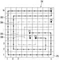
图4A示出沿着图像显示区域DA形成的当前帧图像的移位路线。在这里,图像显示区域DA可以包括m×n矩阵结构的像素PX。例如,当显示面板240的分辨率为1920×1080时,n可以为1920,m可以为1080。FIG. 4A shows a shift route of a current frame image formed along the image display area DA. Here, the image display area DA may include pixels PX in an m×n matrix structure. For example, when the resolution of the
当前帧图像的移位路线可以包括例如从第一点P1延伸到第二点P2的第一路线DI1和从第二点P2延伸到第三点P3的第二路线DI2。如图4A所示,第一点P1和第三点P3可以位于图像显示区域DA的基本上中心的区域中,第二点P2可以位于显示面板240的图像显示区域DA的基本上外围的周边显示区域中。此外,第一路线DI1和第二路线DI2可以彼此互不重叠,并且第一路线DI1和第二路线DI2中的每条可以以彼此围绕的迷宫形式形成。The displacement route of the current frame image may include, for example, a first route DI1 extending from the first point P1 to the second point P2 and a second route DI2 extending from the second point P2 to the third point P3. As shown in FIG. 4A, the first point P1 and the third point P3 may be located in the substantially central area of the image display area DA, and the second point P2 may be located in the substantially peripheral periphery of the image display area DA of the
在本发明构思的该实施例中,第一路线DI1在图像显示区域DA的基本上中心的区域中的第一点P1处开始,并且在到达终点P2之前,具有围绕基本上外围的周边显示区域的路径,该周边显示区域围绕第二路线DI2的大部分路径。然而,本领域普通技术人员应该理解并认识到,除了本文所示的示例之外,像素移位路线的各种布置都在本发明构思的范围内。In this embodiment of the inventive concept, the first route DI1 starts at the first point P1 in the substantially central area of the image display area DA, and has a peripheral display area surrounding the substantially peripheral area before reaching the end point P2. , the perimeter display area surrounds most of the route of the second route DI2. However, those of ordinary skill in the art will understand and appreciate that various arrangements of pixel shifting routes other than the examples shown herein are within the scope of the inventive concept.
处理器100的图像校正器130可以基于从移位范围确定器120提供的移位范围信息SI,将第一图像数据DATA1校正(例如,改变)为第二图像数据DATA2,使得当前帧图像的显示可沿着第一路线DI1和/或第二路线DI2被移位(例如,如图2所示)。The
在该示例中,显示单元200可以在每当从处理器100接收第二图像数据DATA2时显示在例如图4A所示的箭头方向上移位后的当前帧图像。In this example, the
例如,当假设当前帧图像的中心被显示在第一点P1处时,显示单元200可以在每当接收到第二图像数据DATA2时沿着第一路线DI1将当前帧图像的中心的显示移位到第二点P2,并显示当前帧图像。此外,在当前帧图像的中心被移位以在第二点P2处被显示时,显示单元200可以沿着第二路线DI2将正在显示的当前帧图像的中心移位到第三点P3,并显示当前帧图像。如上所述,显示单元200可以在每当从图像校正器130接收到第二图像数据DATA2时沿着第一路线DI1和第二路线DI2将当前帧图像移位,并且沿着移位的路线显示当前帧图像。For example, when it is assumed that the center of the current frame image is displayed at the first point P1, the
参考图4B,移位范围确定器120可以确定与图4A所示的移位路线不同的新的移位路线。Referring to FIG. 4B , the
例如,当前帧图像的移位路线可以包括从第一点P1延伸到第二点P2的第三路线DI3、从第二点P2延伸到第四点P4的第四路线DI4、从第四点P4延伸到第五点P5的第五路线DI5、以及从第五点P5延伸到第三点P3的第六路线DI6。For example, the displacement route of the current frame image may include a third route DI3 extending from the first point P1 to the second point P2, a fourth route DI4 extending from the second point P2 to the fourth point P4, and a fourth route DI4 extending from the fourth point P4. A fifth route DI5 extending to the fifth point P5, and a sixth route DI6 extending from the fifth point P5 to the third point P3.
在图4B中,第一点P1、第三点P3和第四点P4可以位于图像显示区域DA的中心区域(例如基本上中心的区域)中,并且第二点P2和第五点P5可以位于图像显示区域DA的外围周边区域(例如基本上外围的周边区域)中。此外,第三路线DI3至第六路线DI6可以彼此互不重叠,并且第三路线DI3至第六路线DI6中的每条可以以彼此围绕的迷宫形式形成。In FIG. 4B, the first point P1, the third point P3, and the fourth point P4 may be located in a central area (for example, a substantially central area) of the image display area DA, and the second point P2 and the fifth point P5 may be located in The image is displayed in a peripheral peripheral area (for example, a substantially peripheral peripheral area) of the area DA. In addition, the third to sixth routes DI3 to DI6 may not overlap each other, and each of the third to sixth routes DI3 to DI6 may be formed in a maze form surrounding each other.
图像校正器130可以通过使用从移位范围确定器120提供的移位范围信息SI,来将第一图像数据DATA1校正(例如,改变)为第二图像数据DATA2,使得当前帧图像的显示可沿着第三路线DI3至第六路线DI6被移位。The
在该示例中,显示单元200可以在每当从处理器100接收到第二图像数据DATA2时显示在沿着箭头方向上移位后的图像。In this example, the
例如,当假设当前帧图像的中心被显示在第一点P1处时,显示单元200可以在每当接收第二图像数据DATA2时沿着第三路线DI3将当前帧图像的中心的显示移位到第二点P2,然后沿着第四路线DI4将当前帧图像的中心的显示移位到第四点P4,并沿着第五路线DI5将当前帧图像的中心的显示移位到第五点P5,并且沿着第六路线DI6将当前帧图像的中心的显示移位到第三点P3,并显示当前帧图像。For example, when it is assumed that the center of the current frame image is displayed at the first point P1, the
如上所述,显示单元200可以在每当接收到第二图像数据DATA2时沿着第三路线DI3至第六路线DI6将当前帧图像的显示移位,并显示当前帧图像。As described above, the
将参考图4A和图4B对当前帧图像的移位距离进行描述。当比较图4A和图4B时可以看出,当前帧图像沿着第三路线DI3从第一点P1到第二点P2的移位距离比当前帧图像沿着第一路线DI1的移位距离短。The shift distance of the current frame image will be described with reference to FIGS. 4A and 4B . When comparing FIG. 4A and FIG. 4B, it can be seen that the displacement distance of the current frame image along the third route DI3 from the first point P1 to the second point P2 is shorter than the displacement distance of the current frame image along the first route DI1 .
与当前帧图像沿着第一路线DI1移位的情况相比,当当前帧图像沿着第三路线DI3移位时,当前帧图像的中心可以被更快速地移位到图像显示区域DA的外围周边区域(例如,基本上外围的周边区域)。Compared with the case where the current frame image is shifted along the first route DI1, when the current frame image is shifted along the third route DI3, the center of the current frame image can be shifted to the periphery of the image display area DA more quickly A peripheral area (eg, a substantially peripheral peripheral area).
例如,基于亮度值的比较,当设置在图像显示区域DA的中心区域中的像素PX的劣化性能(或潜在劣化性能)相对较大时,当前帧图像可以沿着第三路线DI3移位,与当前帧图像沿着第一路线DI1移位的情况相比,设置在显示器的中心区域中的像素PX的应力可以被更快速地分散到设置在基本上外围的周边区域中的像素PX。For example, based on the comparison of luminance values, when the degradation performance (or potential degradation performance) of the pixels PX disposed in the central area of the image display area DA is relatively large, the current frame image may be shifted along the third route DI3, and Stress of the pixels PX disposed in the central area of the display may be more quickly dispersed to the pixels PX disposed in the substantially peripheral peripheral area compared to a case where the current frame image is shifted along the first route DI1.
因此,移位范围确定器120可以确定像素PX的性能的劣化程度,并且当劣化程度(或潜在劣化)相对较大时,将包括相对较长的移位路线的移位路线确定为当前帧图像的移位路线。Therefore, the
图5是根据本发明构思的第二示例性实施例的处理器的示意性框图。FIG. 5 is a schematic block diagram of a processor according to a second exemplary embodiment of the inventive concept.
基于与根据图2所示的本发明构思的示例性实施例的处理器100的不同点,将对根据图5所示的本发明构思的示例性实施例的处理器100'进行描述。未参考图5而特别描述的部分将遵循根据上述示例性实施例的处理器100的那些部分,并且相同的附图标记指代相同的元件,相似的附图标记指代相似的元件。A processor 100' according to an exemplary embodiment of the inventive concept shown in FIG. 5 will be described based on differences from the
参考图5,处理器100'可以包括例如图像数据生成器110、应力计算单元(或应力计算器)115、移位范围确定器120'、以及图像校正器130。Referring to FIG. 5 , the
图像数据生成器110可以生成用于通过显示单元200来显示当前帧图像的第一图像数据DATA1。图像数据生成器110可以将第一图像数据DATA1提供给图像校正器130。The
应力计算单元115可以基于第一图像数据DATA1分析当前帧图像的亮度分布,并生成应力图。The
特别地,应力计算单元115可以被配置为将包括在显示单元200中的像素PX分组为像素块,计算像素块中的每个像素块的平均亮度值,并生成应力图。在这里,应力图可以是表示包括在显示当前帧图像的像素块中的像素PX的劣化程度的指标。In particular, the
应力计算单元115可以基于当前帧图像的第一图像数据DATA1来生成应力图,并且还可以通过使用从存储器300读取的先前帧图像的第二累积应力图SMAP2来生成第一累积应力图SMAP1。在这里,第一累积应力图SMAP1将包括在显示当前帧图像的像素块中的像素PX的性能的劣化(或潜在劣化)程度表示为累积指标,并且可以通过将当前帧图像的应力图应用于先前帧图像的第二累积应力图SMAP2来生成。The
例如,应力计算单元115可以被配置为通过将当前帧图像的平均亮度值应用于先前帧图像的累积平均亮度值来生成第一累积应力图SMAP1。For example, the
应力计算单元115可以将第一累积应力图SMAP1供应给移位范围确定器120'。The
移位范围确定器120'可以被配置为基于分析第一累积应力图SMAP1来确定对像素的应力是否应经由像素移位和特定移位路线来分散,并且基于所确定的结果来确定当前帧图像的移位路线。移位范围确定器120'可以将包括所确定的移位路线的移位范围信息SI提供给图像校正器130。The displacement range determiner 120' may be configured to determine whether the stress on a pixel should be dispersed via pixel displacement and a specific displacement route based on analyzing the first accumulated stress map SMAP1, and determine the current frame image based on the determined result the displacement route. The
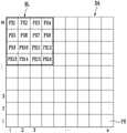
图6是示出根据本发明构思的示例性实施例的通过处理器将像素分组为像素组的方法的概念图。FIG. 6 is a conceptual diagram illustrating a method of grouping pixels into pixel groups by a processor according to an exemplary embodiment of the inventive concept. Referring to FIG.
参考图6,应力计算单元115可以将包括在图像显示区域DA中的像素PX分组为多个像素块BL。包括在像素块BL中的每个像素块中的像素PX可以被设置为彼此相邻。Referring to FIG. 6 , the
根据示例性实施例,应力计算单元115可以将像素块BL中的像素PX分组为p×q矩阵结构(在这里,p和q是自然数)。According to an exemplary embodiment, the
例如,应力计算单元115可以将4×4矩阵结构的像素PX1至PX16分组为一个像素块BL,并且还可以将剩余的像素PX分组为包括4×4矩阵结构的像素PX的像素块BL。For example, the
图7是示出根据本发明构思的示例性实施例的通过处理器来生成第一累积应力图的方法的概念图。FIG. 7 is a conceptual diagram illustrating a method of generating a first cumulative stress map by a processor according to an exemplary embodiment of the inventive concept.
参考图7,应力计算单元115可以将包括在像素块BL中的每个像素块中的像素PX的亮度值平均,并且计算用于当前帧图像的平均亮度值,并且生成包括每个像素块BL的平均亮度值的当前帧图像的应力图。例如,应力图可以包括一组亮度值,多个像素块BL分别以该组亮度值来发光,并且可以显示当前帧图像。Referring to FIG. 7, the
此外,应力计算单元115可以针对每个帧图像来计算多个像素块BL中的每个像素块的平均亮度值,并且针对每个帧图像再次将计算出的平均亮度值平均,并且针对多个像素块BL中的每个像素块来计算累积平均亮度值。例如,第二累积应力图SMAP2可以包括一组累积平均亮度值,像素块BL从初始帧图像至先前帧图像分别以该组累积平均亮度值来发光。In addition, the
应力计算单元115可以将第二累积应力图SMAP2存储在存储器300中,并且从存储器300读取第二累积应力图SMAP2,以生成第一累积应力图SMAP1。The
应力计算单元115可以通过将应力图应用于第二累积应力图SMAP2来生成第一累积应力图SMAP1。例如,应力计算单元115可以计算累积平均亮度值,多个像素块BL从初始帧图像至当前帧图像分别以该累积平均亮度值来发光,并且生成第一累积应力图SMAP1。The
移位范围确定器120'可以基于分析第一累积应力图SMAP1,来确定是否将用于显示图像的像素的应力分散。The displacement range determiner 120' may determine whether to disperse the stress of the pixels for displaying an image based on analyzing the first accumulated stress map SMAP1.
根据示例性实施例,移位范围确定器120'计算像素块BL之中的相邻行之间的第一亮度差以及像素块BL之中的相邻列之间的第二亮度差,并且当第一亮度差和第二亮度差中的至少一个大于参考亮度差时,移位范围确定器120'可以确定包括在像素块BL中的像素PX的劣化可使用像素移位来解决。According to an exemplary embodiment, the shift range determiner 120' calculates a first luminance difference between adjacent rows in the pixel block BL and a second luminance difference between adjacent columns in the pixel block BL, and when When at least one of the first luminance difference and the second luminance difference is greater than the reference luminance difference, the shift range determiner 120' may determine that degradation of the pixel PX included in the pixel block BL can be resolved using pixel shifting.
例如,移位范围确定器120'可以将像素块的累积平均亮度值进行比较。例如,移位范围确定器120'可以将第五像素块BL5的累积平均亮度值LU5和第二像素块BL2的累积平均亮度值LU1进行比较,并且将第五像素块BL5的累积平均亮度值LU5和第八像素块BL8的累积平均亮度值LU4进行比较,以计算第一亮度差。此外,移位范围确定器120'可以将第五像素块BL5的累积平均亮度值LU5和第四像素块BL4的累积平均亮度值LU2进行比较,并且将第五像素块BL5的累积平均亮度值LU5和第六像素块BL6的累积平均亮度值LU3进行比较,以计算第二亮度差。当第一亮度差和第二亮度差中的任意一个大于参考亮度差时,移位范围确定器120'可以确定包括在第五像素块BL5中的像素PX的劣化(或潜在劣化)相对较大。For example, the shift range determiner 120' may compare the cumulative average luminance values of the pixel blocks. For example, the shift range determiner 120' may compare the cumulative average luminance value LU5 of the fifth pixel block BL5 with the cumulative average luminance value LU1 of the second pixel block BL2, and compare the cumulative average luminance value LU5 of the fifth pixel block BL5 It is compared with the cumulative average luminance value LU4 of the eighth pixel block BL8 to calculate the first luminance difference. In addition, the shift range determiner 120' may compare the cumulative average luminance value LU5 of the fifth pixel block BL5 with the cumulative average luminance value LU2 of the fourth pixel block BL4, and compare the cumulative average luminance value LU5 of the fifth pixel block BL5 It is compared with the cumulative average luminance value LU3 of the sixth pixel block BL6 to calculate the second luminance difference. When any one of the first luminance difference and the second luminance difference is greater than the reference luminance difference, the shift range determiner 120' may determine that the degradation (or potential degradation) of the pixel PX included in the fifth pixel block BL5 is relatively large .
移位范围确定器120'可以基于所确定的劣化程度来确定当前帧图像的移位路线。移位范围确定器120'可以将包括与像素劣化程度对应的大量路线的移位路线设置为当前帧图像的移位路线。The shift range determiner 120' may determine a shift route of the current frame image based on the determined degree of degradation. The shift range determiner 120' may set a shift route including a large number of routes corresponding to the degree of pixel degradation as the shift route of the current frame image.
例如,当相邻设置的像素块BL之间的亮度差小于参考亮度差时,移位范围确定器120'可以将包括图4A所示的第一路线DI1和第二路线DI2的移位路线确定为当前帧图像的移位路线,并且当相邻配置的像素块BL之间的亮度差大于参考亮度差时,移位范围确定器120'可以将包括图4B所示的第三路线DI3至第六路线DI6的移位路线确定为当前帧图像的移位路线。For example, when the luminance difference between adjacently arranged pixel blocks BL is smaller than the reference luminance difference, the shifting range determiner 120' may determine the shifting route including the first route DI1 and the second route DI2 shown in FIG. 4A is the displacement route of the current frame image, and when the brightness difference between adjacently configured pixel blocks BL is greater than the reference brightness difference, the shift range determiner 120' may include the third route DI3 to the first route shown in FIG. 4B The shifting route of the six-way DI6 is determined as the shifting route of the current frame image.
图8是示出根据本发明构思的示例性实施例的通过显示设备来显示图像的方法的流程图。FIG. 8 is a flowchart illustrating a method of displaying an image through a display device according to an exemplary embodiment of the inventive concept.
参考图8,移位范围确定器120可以基于当前帧图像的第一图像数据DATA1来确定包括在显示单元200中的像素PX的劣化程度(S100),并且确定当前帧图像的移位路线,以与所确定的像素的劣化程度对应(S110)。在这种情况下,移位路线可以包括多条路线,例如,移位路线的长度差可以导致不同量的像素应力被分散。因此,可以考虑所确定的劣化程度来确定移位路线。Referring to FIG. 8 , the
图像校正器130可以将第一图像数据DATA1校正为第二图像数据DATA2,使得当前帧图像沿着移位路线被移位(S120)The
显示单元200可以通过使用第二图像数据DATA2来显示沿着移位路线被移位的当前帧图像。The
图9是示出根据本发明构思的实施例的显示设备的操作的流程图,其中移位范围确定器分析是否将数据图像的显示移位。FIG. 9 is a flowchart illustrating an operation of a display device according to an embodiment of the inventive concept, wherein a shift range determiner analyzes whether to shift a display of a data image.
处理器100'的图像数据生成器110生成用于显示当前帧图像的第一图像数据DATA1(S200)。The
处理器100'的应力计算器115被配置为基于第一图像数据DATA1来分析当前帧图像的亮度分布并生成应力图(S210)。The
应力计算器115将当前帧图像的应力图信息应用于先前帧图像的累积应力图(S220)。The
移位范围确定器120'基于应力图信息来确定是否有任何像素具有比周边像素高的亮度值(S230)。The shift range determiner 120' determines whether any pixel has a higher brightness value than surrounding pixels based on the stress map information (S230).
如果存在具有比周边像素高的亮度值的像素,则像素劣化的可能性增加,并且移位范围确定器120'发送移位范围信息SI以将图像的显示移位。图像校正器130可以将第一图像数据DATA1校正为第二图像数据DATA2,并将第二图像数据DATA2发送到时序控制器210,以生成与第二图像数据DATA2对应的数据信号DS(S240)。If there is a pixel having a higher luminance value than surrounding pixels, the possibility of pixel degradation increases, and the shift range determiner 120' transmits the shift range information SI to shift the display of the image. The
然而,如果移位范围确定器120'确定不存在具有比周边像素高的亮度值的像素,则移位范围确定器120'向图像校正器130发送移位范围信息SI,指示不执行图像的移位。然后,图像校正器130可以将第一图像数据DATA1发送到时序控制器210,以生成与第一图像数据DATA1对应的数据信号DS(S250)。However, if the shift range determiner 120' determines that there is no pixel having a higher luminance value than surrounding pixels, the shift range determiner 120' transmits shift range information SI to the
已经参考附图中所示的示例性实施例对本公开进行了描述,但是示例性实施例仅仅是说明性的,本领域技术人员将会认识到,可以实施对本发明构思的实施例的各种修改。The present disclosure has been described with reference to the exemplary embodiments shown in the drawings, but the exemplary embodiments are for illustration only, and those skilled in the art will recognize that various modifications to the embodiments of the inventive concept may be implemented .
Claims (9)
Translated fromChineseApplications Claiming Priority (3)
| Application Number | Priority Date | Filing Date | Title |
|---|---|---|---|
| KR1020160087071AKR102529270B1 (en) | 2016-07-08 | 2016-07-08 | Display device and method for displaying image using display device |
| KR10-2016-0087071 | 2016-07-08 | ||
| CN201710551216.0ACN107591118B (en) | 2016-07-08 | 2017-07-07 | Method of displaying image in display device |
Related Parent Applications (1)
| Application Number | Title | Priority Date | Filing Date |
|---|---|---|---|
| CN201710551216.0ADivisionCN107591118B (en) | 2016-07-08 | 2017-07-07 | Method of displaying image in display device |
Publications (2)
| Publication Number | Publication Date |
|---|---|
| CN115482766Atrue CN115482766A (en) | 2022-12-16 |
| CN115482766B CN115482766B (en) | 2025-09-05 |
Family
ID=60910489
Family Applications (4)
| Application Number | Title | Priority Date | Filing Date |
|---|---|---|---|
| CN202211280730.2AActiveCN115482767B (en) | 2016-07-08 | 2017-07-07 | Method for displaying image in display device |
| CN201710551216.0AActiveCN107591118B (en) | 2016-07-08 | 2017-07-07 | Method of displaying image in display device |
| CN202211280116.6AActiveCN115512638B (en) | 2016-07-08 | 2017-07-07 | Display device and method of displaying image in the display device |
| CN202211280122.1AActiveCN115482766B (en) | 2016-07-08 | 2017-07-07 | Method for displaying an image in a display device |
Family Applications Before (3)
| Application Number | Title | Priority Date | Filing Date |
|---|---|---|---|
| CN202211280730.2AActiveCN115482767B (en) | 2016-07-08 | 2017-07-07 | Method for displaying image in display device |
| CN201710551216.0AActiveCN107591118B (en) | 2016-07-08 | 2017-07-07 | Method of displaying image in display device |
| CN202211280116.6AActiveCN115512638B (en) | 2016-07-08 | 2017-07-07 | Display device and method of displaying image in the display device |
Country Status (3)
| Country | Link |
|---|---|
| US (4) | US10529267B2 (en) |
| KR (2) | KR102529270B1 (en) |
| CN (4) | CN115482767B (en) |
Families Citing this family (18)
| Publication number | Priority date | Publication date | Assignee | Title |
|---|---|---|---|---|
| KR102250449B1 (en)* | 2014-09-19 | 2021-05-12 | 삼성디스플레이 주식회사 | Display device and method for correcting image of display device |
| KR102529270B1 (en) | 2016-07-08 | 2023-05-09 | 삼성디스플레이 주식회사 | Display device and method for displaying image using display device |
| KR102348651B1 (en)* | 2017-11-21 | 2022-01-07 | 엘지전자 주식회사 | Organic light emitting diode display device and method for operating thereof |
| KR102521949B1 (en)* | 2018-08-31 | 2023-04-18 | 삼성디스플레이 주식회사 | Image compensator and method for driving display device |
| KR102571750B1 (en)* | 2018-10-04 | 2023-08-28 | 삼성디스플레이 주식회사 | Display device and method for displaying image using display device |
| KR102771517B1 (en)* | 2019-04-12 | 2025-02-26 | 삼성디스플레이 주식회사 | Display device and method of driving the same |
| CN110349539A (en)* | 2019-06-24 | 2019-10-18 | 深圳市华星光电半导体显示技术有限公司 | A kind of display driving method of display panel, display panel and display device |
| JP7391552B2 (en)* | 2019-06-27 | 2023-12-05 | エルジー ディスプレイ カンパニー リミテッド | Display control device and display control method |
| KR20210038766A (en)* | 2019-09-30 | 2021-04-08 | 삼성디스플레이 주식회사 | Display device and method of driving the same |
| KR102760598B1 (en) | 2019-11-04 | 2025-02-04 | 삼성디스플레이 주식회사 | Display device and driving method thereof |
| KR102738966B1 (en)* | 2019-12-18 | 2024-12-06 | 주식회사 엘엑스세미콘 | Source driver and display device including the same |
| KR102786736B1 (en)* | 2020-08-25 | 2025-03-28 | 삼성디스플레이 주식회사 | Display device and method of operating display device |
| US11942055B2 (en)* | 2021-02-01 | 2024-03-26 | Samsung Electronics Co., Ltd. | Display system performing display panel compensation and method of compensating display panel |
| KR20220160162A (en) | 2021-05-26 | 2022-12-06 | 삼성디스플레이 주식회사 | Display apparatus and method of driving display panel using the same |
| WO2023282494A1 (en)* | 2021-07-09 | 2023-01-12 | 삼성전자주식회사 | Display device and control method therefor |
| EP4322143A4 (en)* | 2021-07-09 | 2024-08-07 | Samsung Electronics Co., Ltd. | DISPLAY DEVICE AND CONTROL METHOD THEREFOR |
| KR20230050536A (en)* | 2021-10-07 | 2023-04-17 | 삼성디스플레이 주식회사 | Display device compensating for light stress |
| KR20230074325A (en)* | 2021-11-19 | 2023-05-30 | 삼성디스플레이 주식회사 | Display device |
Citations (11)
| Publication number | Priority date | Publication date | Assignee | Title |
|---|---|---|---|---|
| CN1224887A (en)* | 1997-12-31 | 1999-08-04 | 三星电子株式会社 | Liquid crystal display device, manufacturing method and driving method thereof |
| US20050204313A1 (en)* | 2004-03-09 | 2005-09-15 | Pioneer Corporation | Display screen burn prevention method |
| US20080111886A1 (en)* | 2006-11-13 | 2008-05-15 | Samsung Electronics Co., Ltd | Image display device and method thereof |
| CN101647284A (en)* | 2007-04-20 | 2010-02-10 | 汤姆逊许可公司 | Method and apparatus for selecting a scan path for elements of a block in spatial domain image encoding and decoding |
| CN102595022A (en)* | 2011-01-10 | 2012-07-18 | 联咏科技股份有限公司 | Multimedia device and motion compensation method thereof |
| CN103765293A (en)* | 2011-08-24 | 2014-04-30 | 索尼公司 | Display device and display control method |
| CN103843318A (en)* | 2011-09-30 | 2014-06-04 | 佳能株式会社 | Image capturing apparatus and control method thereof |
| US20150077406A1 (en)* | 2013-09-17 | 2015-03-19 | Samsung Display Co., Ltd. | Display device and method for driving the same |
| CN105549283A (en)* | 2014-10-22 | 2016-05-04 | 三星显示有限公司 | Display apparatus |
| CN105684066A (en)* | 2013-10-24 | 2016-06-15 | Lg电子株式会社 | Multi-vision and its control method |
| US20160189336A1 (en)* | 2014-12-29 | 2016-06-30 | Samsung Display Co., Ltd. | Display device |
Family Cites Families (40)
| Publication number | Priority date | Publication date | Assignee | Title |
|---|---|---|---|---|
| DE69822936T2 (en)* | 1997-07-24 | 2004-08-12 | Matsushita Electric Industrial Co., Ltd., Kadoma | Image display device and image evaluation device |
| JP2000231364A (en) | 1999-02-09 | 2000-08-22 | Fuji Photo Film Co Ltd | Image display device |
| JP2001034223A (en)* | 1999-07-23 | 2001-02-09 | Matsushita Electric Ind Co Ltd | Moving image display method and moving image display device using the same |
| EP1271459A1 (en)* | 2001-06-27 | 2003-01-02 | Deutsche Thomson-Brandt Gmbh | Method and device for compensating burning effects on display panel |
| AU2003211470A1 (en)* | 2002-03-04 | 2003-09-16 | Sanyo Electric Co., Ltd. | Organic electroluminescence display and its application |
| JP3685179B2 (en)* | 2003-02-20 | 2005-08-17 | ソニー株式会社 | Image signal processing apparatus and processing method, and image display apparatus using the same |
| JP2005148558A (en)* | 2003-11-18 | 2005-06-09 | Sony Corp | Display device and driving method therefor |
| KR20050105574A (en) | 2004-04-30 | 2005-11-04 | 엘지.필립스 엘시디 주식회사 | Lcd and driving method thereof |
| JP2006013913A (en)* | 2004-06-25 | 2006-01-12 | Funai Electric Co Ltd | Plasma display device |
| KR100683693B1 (en) | 2004-11-10 | 2007-02-15 | 삼성에스디아이 주식회사 | Light emitting device |
| KR100719114B1 (en)* | 2005-07-19 | 2007-05-17 | 삼성전자주식회사 | Display device and method for shifting pixel position |
| US20070109284A1 (en)* | 2005-08-12 | 2007-05-17 | Semiconductor Energy Laboratory Co., Ltd. | Display device |
| US20070222712A1 (en)* | 2005-08-23 | 2007-09-27 | Yutaka Chiaki | Image Display Apparatus and Method of Driving the Same |
| US20070096767A1 (en)* | 2005-10-28 | 2007-05-03 | Chang-Hung Tsai | Method of preventing display panel from burn-in defect |
| JP2007171700A (en)* | 2005-12-23 | 2007-07-05 | Toshiba Corp | Video display device and video display method |
| KR100769194B1 (en)* | 2006-02-06 | 2007-10-23 | 엘지.필립스 엘시디 주식회사 | Flat panel display, manufacturing method, image quality control method and device |
| JP2007221269A (en)* | 2006-02-14 | 2007-08-30 | Canon Inc | Display signal control device, display signal control method, program, and storage medium |
| JP2007271678A (en)* | 2006-03-30 | 2007-10-18 | Pioneer Electronic Corp | Image display device and burning preventing method for display screen |
| JP2008039868A (en)* | 2006-08-02 | 2008-02-21 | Victor Co Of Japan Ltd | Liquid crystal display device |
| KR101270167B1 (en)* | 2006-08-17 | 2013-05-31 | 삼성전자주식회사 | Method and apparatus of low complexity for compressing image, method and apparatus of low complexity for reconstructing image |
| JP4615508B2 (en)* | 2006-12-27 | 2011-01-19 | シャープ株式会社 | Image display apparatus and method, image processing apparatus and method |
| KR101393627B1 (en) | 2007-03-02 | 2014-05-12 | 삼성디스플레이 주식회사 | Display device and control method of the same |
| JP5259112B2 (en)* | 2007-03-27 | 2013-08-07 | 京セラ株式会社 | Portable electronic devices |
| JP2009103889A (en)* | 2007-10-23 | 2009-05-14 | Hitachi Ltd | Image display device and image display method |
| KR100902238B1 (en)* | 2008-01-18 | 2009-06-11 | 삼성모바일디스플레이주식회사 | Organic light emitting display device and driving method thereof |
| JP2009194420A (en)* | 2008-02-12 | 2009-08-27 | Seiko Epson Corp | Pixel shift measuring device, image display device, and pixel shift measuring method |
| JP5493707B2 (en)* | 2009-10-28 | 2014-05-14 | ソニー株式会社 | Display device and display device control method |
| KR101779076B1 (en)* | 2010-09-14 | 2017-09-19 | 삼성디스플레이 주식회사 | Organic Light Emitting Display Device with Pixel |
| US8705892B2 (en)* | 2010-10-26 | 2014-04-22 | 3Ditize Sl | Generating three-dimensional virtual tours from two-dimensional images |
| KR101903748B1 (en)* | 2011-10-07 | 2018-10-04 | 삼성디스플레이 주식회사 | Display device |
| CN102333200A (en)* | 2011-10-28 | 2012-01-25 | 冠捷显示科技(厦门)有限公司 | Method for realizing image motion compensation of liquid crystal television by utilizing two-dimensional light-emitting diode (LED) local dimming technology |
| JP2015158524A (en)* | 2012-06-12 | 2015-09-03 | パナソニック株式会社 | Driving method of image display device, image display device and image display system |
| JP2014038229A (en)* | 2012-08-17 | 2014-02-27 | Sony Corp | Image processing apparatus, image processing method, and program |
| KR102057288B1 (en)* | 2013-02-21 | 2019-12-19 | 삼성디스플레이 주식회사 | Organic Light Emitting Display and Driving Method Thereof |
| KR20150006221A (en)* | 2013-07-08 | 2015-01-16 | 삼성전자주식회사 | Display apparatus and control method thereof |
| KR102250449B1 (en)* | 2014-09-19 | 2021-05-12 | 삼성디스플레이 주식회사 | Display device and method for correcting image of display device |
| KR102336090B1 (en)* | 2014-12-15 | 2021-12-07 | 삼성디스플레이 주식회사 | Orgainic light emitting display and driving method for the same |
| KR102322708B1 (en)* | 2014-12-24 | 2021-11-09 | 엘지디스플레이 주식회사 | Organic light emitting diode display device and method of sensing device characteristic |
| KR102549919B1 (en) | 2016-07-08 | 2023-07-04 | 삼성디스플레이 주식회사 | Display device and method for displaying image using display device |
| KR102529270B1 (en) | 2016-07-08 | 2023-05-09 | 삼성디스플레이 주식회사 | Display device and method for displaying image using display device |
- 2016
- 2016-07-08KRKR1020160087071Apatent/KR102529270B1/enactiveActive
- 2017
- 2017-06-14USUS15/622,788patent/US10529267B2/enactiveActive
- 2017-07-07CNCN202211280730.2Apatent/CN115482767B/enactiveActive
- 2017-07-07CNCN201710551216.0Apatent/CN107591118B/enactiveActive
- 2017-07-07CNCN202211280116.6Apatent/CN115512638B/enactiveActive
- 2017-07-07CNCN202211280122.1Apatent/CN115482766B/enactiveActive
- 2020
- 2020-01-06USUS16/734,893patent/US11436958B2/enactiveActive
- 2022
- 2022-08-05USUS17/817,706patent/US11887517B2/enactiveActive
- 2023
- 2023-04-28KRKR1020230056609Apatent/KR102730394B1/enactiveActive
- 2023-12-21USUS18/392,081patent/US20240119876A1/enactivePending
Patent Citations (12)
| Publication number | Priority date | Publication date | Assignee | Title |
|---|---|---|---|---|
| CN1224887A (en)* | 1997-12-31 | 1999-08-04 | 三星电子株式会社 | Liquid crystal display device, manufacturing method and driving method thereof |
| US20050204313A1 (en)* | 2004-03-09 | 2005-09-15 | Pioneer Corporation | Display screen burn prevention method |
| US20080111886A1 (en)* | 2006-11-13 | 2008-05-15 | Samsung Electronics Co., Ltd | Image display device and method thereof |
| CN101183518A (en)* | 2006-11-13 | 2008-05-21 | 三星电子株式会社 | Image display device and method thereof |
| CN101647284A (en)* | 2007-04-20 | 2010-02-10 | 汤姆逊许可公司 | Method and apparatus for selecting a scan path for elements of a block in spatial domain image encoding and decoding |
| CN102595022A (en)* | 2011-01-10 | 2012-07-18 | 联咏科技股份有限公司 | Multimedia device and motion compensation method thereof |
| CN103765293A (en)* | 2011-08-24 | 2014-04-30 | 索尼公司 | Display device and display control method |
| CN103843318A (en)* | 2011-09-30 | 2014-06-04 | 佳能株式会社 | Image capturing apparatus and control method thereof |
| US20150077406A1 (en)* | 2013-09-17 | 2015-03-19 | Samsung Display Co., Ltd. | Display device and method for driving the same |
| CN105684066A (en)* | 2013-10-24 | 2016-06-15 | Lg电子株式会社 | Multi-vision and its control method |
| CN105549283A (en)* | 2014-10-22 | 2016-05-04 | 三星显示有限公司 | Display apparatus |
| US20160189336A1 (en)* | 2014-12-29 | 2016-06-30 | Samsung Display Co., Ltd. | Display device |
Non-Patent Citations (1)
| Title |
|---|
| 姜有燕;汤勇明;屠彦;: "等离子体显示屏"万年残像"现象的研究", 电子器件, no. 04, 30 December 2005 (2005-12-30)* |
Also Published As
| Publication number | Publication date |
|---|---|
| CN115482767B (en) | 2025-08-01 |
| CN107591118A (en) | 2018-01-16 |
| US10529267B2 (en) | 2020-01-07 |
| KR20230069886A (en) | 2023-05-19 |
| CN107591118B (en) | 2022-11-04 |
| US11436958B2 (en) | 2022-09-06 |
| KR102730394B1 (en) | 2024-11-18 |
| US11887517B2 (en) | 2024-01-30 |
| KR102529270B1 (en) | 2023-05-09 |
| KR20180006586A (en) | 2018-01-18 |
| CN115482766B (en) | 2025-09-05 |
| US20240119876A1 (en) | 2024-04-11 |
| US20220375375A1 (en) | 2022-11-24 |
| CN115512638A (en) | 2022-12-23 |
| CN115482767A (en) | 2022-12-16 |
| US20200143725A1 (en) | 2020-05-07 |
| CN115512638B (en) | 2025-08-01 |
| US20180012530A1 (en) | 2018-01-11 |
Similar Documents
| Publication | Publication Date | Title |
|---|---|---|
| CN107591118B (en) | Method of displaying image in display device | |
| CN107591121B (en) | Method of displaying image by using display device | |
| KR102455323B1 (en) | Display device and operation method of the same | |
| KR102654711B1 (en) | Display apparatus and method of driving the same | |
| KR20160082204A (en) | Display panel having a scan driver and method of operating the same | |
| CN108091291B (en) | display device | |
| KR20160084950A (en) | Curved display and a driving method of the same | |
| CN106847199A (en) | Display device and its manufacture method | |
| KR102691216B1 (en) | Display device and electronic device having the same | |
| KR20200082347A (en) | Device and method for generating luminance compensation data based on mura characteristic and device and method for performing luminance compensation | |
| CN114041182A (en) | Reducing screen corner bezel size | |
| JP2015125243A (en) | Multi-display system, image display apparatus, screen control method and program | |
| CN114758608A (en) | Splicing display | |
| US9041278B2 (en) | Display panel, organic light emitting display device having the same, and method of manufacturing a display panel | |
| KR102508992B1 (en) | Image processing device and image processing method | |
| US11769442B2 (en) | Light-emitting display device preventing occurrence of compensation deviation and driving method thereof | |
| US20140009446A1 (en) | Display panel, organic light emitting display device having the same, and method of manufacturing a display panel | |
| CN117593971A (en) | Display device and image display method thereof | |
| CN119580612A (en) | Method for generating compensation data and display device | |
| KR20240065633A (en) | Control device to drive display panel, display device including the same, method of operating the same |
Legal Events
| Date | Code | Title | Description |
|---|---|---|---|
| PB01 | Publication | ||
| PB01 | Publication | ||
| SE01 | Entry into force of request for substantive examination | ||
| SE01 | Entry into force of request for substantive examination | ||
| GR01 | Patent grant | ||
| GR01 | Patent grant |