CN115480072A - Mechanical isolation type dual-redundancy hydraulic speed measurement rotary transformer sensor - Google Patents
Mechanical isolation type dual-redundancy hydraulic speed measurement rotary transformer sensorDownload PDFInfo
- Publication number
- CN115480072A CN115480072ACN202211199148.3ACN202211199148ACN115480072ACN 115480072 ACN115480072 ACN 115480072ACN 202211199148 ACN202211199148 ACN 202211199148ACN 115480072 ACN115480072 ACN 115480072A
- Authority
- CN
- China
- Prior art keywords
- cavity
- rotor assembly
- bearing
- stator
- rotor
- Prior art date
- Legal status (The legal status is an assumption and is not a legal conclusion. Google has not performed a legal analysis and makes no representation as to the accuracy of the status listed.)
- Pending
Links
Images


Classifications
- G—PHYSICS
- G01—MEASURING; TESTING
- G01P—MEASURING LINEAR OR ANGULAR SPEED, ACCELERATION, DECELERATION, OR SHOCK; INDICATING PRESENCE, ABSENCE, OR DIRECTION, OF MOVEMENT
- G01P3/00—Measuring linear or angular speed; Measuring differences of linear or angular speeds
- F—MECHANICAL ENGINEERING; LIGHTING; HEATING; WEAPONS; BLASTING
- F04—POSITIVE - DISPLACEMENT MACHINES FOR LIQUIDS; PUMPS FOR LIQUIDS OR ELASTIC FLUIDS
- F04C—ROTARY-PISTON, OR OSCILLATING-PISTON, POSITIVE-DISPLACEMENT MACHINES FOR LIQUIDS; ROTARY-PISTON, OR OSCILLATING-PISTON, POSITIVE-DISPLACEMENT PUMPS
- F04C14/00—Control of, monitoring of, or safety arrangements for, machines, pumps or pumping installations
- F04C14/28—Safety arrangements; Monitoring
- G—PHYSICS
- G01—MEASURING; TESTING
- G01P—MEASURING LINEAR OR ANGULAR SPEED, ACCELERATION, DECELERATION, OR SHOCK; INDICATING PRESENCE, ABSENCE, OR DIRECTION, OF MOVEMENT
- G01P1/00—Details of instruments
- G—PHYSICS
- G01—MEASURING; TESTING
- G01P—MEASURING LINEAR OR ANGULAR SPEED, ACCELERATION, DECELERATION, OR SHOCK; INDICATING PRESENCE, ABSENCE, OR DIRECTION, OF MOVEMENT
- G01P1/00—Details of instruments
- G01P1/02—Housings
- G01P1/026—Housings for speed measuring devices, e.g. pulse generator
- G—PHYSICS
- G01—MEASURING; TESTING
- G01P—MEASURING LINEAR OR ANGULAR SPEED, ACCELERATION, DECELERATION, OR SHOCK; INDICATING PRESENCE, ABSENCE, OR DIRECTION, OF MOVEMENT
- G01P13/00—Indicating or recording presence, absence, or direction, of movement
- G01P13/02—Indicating direction only, e.g. by weather vane
- G01P13/04—Indicating positive or negative direction of a linear movement or clockwise or anti-clockwise direction of a rotational movement
Landscapes
- Physics & Mathematics (AREA)
- General Physics & Mathematics (AREA)
- Engineering & Computer Science (AREA)
- Mechanical Engineering (AREA)
- General Engineering & Computer Science (AREA)
- Transmission And Conversion Of Sensor Element Output (AREA)
Abstract
Translated fromChinese
Description
Translated fromChinese技术领域technical field
本发明属于传感器领域,尤其涉及一种机械隔离式双余度液压测速旋变传感器。The invention belongs to the field of sensors, in particular to a mechanically isolated dual-redundancy hydraulic speed-measuring resolver sensor.
背景技术Background technique
现有的测速旋变传感器,一般采用轴端轴封密封,使高压液压油不进入如产品内部,但增大了转轴的扭矩,降低了齿轮泵的工作效率。有的是采用航插端灌封的方式,使液压油密封在产品内部,此种方式不仅对灌封工艺要求严格,还对灌封胶及航插的类型要求苛刻,同时长期处于液压油中的线圈寿命也会降低,而且这种方式无法百分百保证液压油不泄露,可靠性不高,因此无法长期安全有效的在高压的液压油环境中使用。Existing speed-measuring resolver sensors are generally sealed with a shaft-end shaft seal to prevent high-pressure hydraulic oil from entering the interior of the product, but the torque of the rotating shaft is increased and the working efficiency of the gear pump is reduced. Some use the method of potting the aviation plug end to seal the hydraulic oil inside the product. This method not only has strict requirements on the potting process, but also has strict requirements on the type of potting glue and aviation plug. At the same time, the coils that have been in the hydraulic oil for a long time The service life will also be reduced, and this method cannot 100% guarantee that the hydraulic oil will not leak, and the reliability is not high, so it cannot be used safely and effectively in a high-pressure hydraulic oil environment for a long time.
发明内容Contents of the invention
本发明旨在解决上述问题,提供一种分体式结构可实现长期不间断在耐压环境工作的机械隔离式双余度液压测速旋变传感器。The present invention aims to solve the above problems, and provides a mechanically isolated dual-redundancy hydraulic speed measuring resolver sensor with a split structure that can realize long-term uninterrupted work in a pressure-resistant environment.
本发明所述机械隔离式双余度液压测速旋变传感器,包括腔体、转子组件和定子组件;The mechanically isolated dual-redundancy hydraulic speed measuring resolver of the present invention includes a cavity, a rotor assembly and a stator assembly;
所述腔体的前端设置一凸台状安装法兰;所述腔体的内部设置一轴承孔;所述轴承孔位于腔体的尾端;The front end of the cavity is provided with a boss-shaped mounting flange; the inside of the cavity is provided with a bearing hole; the bearing hole is located at the tail end of the cavity;
所述转子组件的前端和尾端均设置一转轴;Both the front end and the tail end of the rotor assembly are provided with a rotating shaft;
所述转子组件设置于前述腔体的内腔内部;The rotor assembly is arranged inside the inner cavity of the aforementioned cavity;
所述转子组件的前端和尾端均设置一轴承;所述转子组件通过前述转轴与轴承相连接;A bearing is provided at the front end and the tail end of the rotor assembly; the rotor assembly is connected to the bearing through the aforementioned rotating shaft;
位于所述转子组件尾端的轴承设置于前述轴承孔内;The bearing located at the tail end of the rotor assembly is arranged in the aforementioned bearing hole;
所述转子组件前端的转轴设置为花键转轴;The shaft at the front end of the rotor assembly is set as a spline shaft;
所述凸台状安装法兰的前端固定设置有轴承端盖;所述轴承端盖上设置一通孔;The front end of the boss-shaped mounting flange is fixedly provided with a bearing end cover; a through hole is arranged on the bearing end cover;
前述花键转轴前端从所述通孔内穿过位于腔体外部;The front end of the spline shaft passes through the through hole and is located outside the cavity;
所述定子组件套设于前述腔体外壁上。The stator assembly is sheathed on the outer wall of the cavity.
进一步,本发明所述机械隔离式双余度液压测速旋变传感器,所述腔体的尾端外壁上设置有螺纹;Further, in the mechanically isolated double-redundancy hydraulic speed measuring resolver of the present invention, the outer wall of the tail end of the cavity is provided with threads;
所述腔体的尾端设置有压紧螺圈;所述压紧螺圈通过前述螺纹与腔体相连接;The tail end of the cavity is provided with a compression coil; the compression coil is connected to the cavity through the aforementioned thread;
所述压紧螺圈与前述定子组件之间设置有定子支撑圈。A stator supporting ring is arranged between the compression coil and the aforementioned stator assembly.
进一步,本发明所述机械隔离式双余度液压测速旋变传感器,所述转子组件为双通道转子组件;Further, in the mechanically isolated dual-redundancy hydraulic speed measuring resolver sensor of the present invention, the rotor assembly is a dual-channel rotor assembly;
所述定子组件包括两个旋变定子和两个环变定子;前述两个环变定子设置于前述两个旋变定子之间;通过对转子组件和定子组件的双余度设置,实现了双余度输出,从而有效增大了信号冗余,提高了传感器的可靠性。The stator assembly includes two resolver stators and two ring change stators; the aforementioned two ring change stators are arranged between the aforementioned two resolver stators; through the double redundancy setting of the rotor assembly and the stator assembly, dual Redundant output, which effectively increases the signal redundancy and improves the reliability of the sensor.
进一步,本发明所述机械隔离式双余度液压测速旋变传感器,所述腔体的外部设置有一外壳;Further, in the mechanically isolated dual-redundancy hydraulic speed measuring resolver sensor of the present invention, a housing is arranged outside the cavity;
所述外壳的侧壁上设置一开孔;An opening is provided on the side wall of the housing;
所述外壳的侧壁上与前述开孔对应的位置处设置有航插安装座;An aviation plug mounting seat is provided at a position corresponding to the aforementioned opening on the side wall of the housing;
所述航插安装座的一侧设置有连接器;将连接器与前述腔体内的定子组件通过线路相连接,通过连接器与外部数据采集设备相连接,实现传感器监测数据的传输。A connector is provided on one side of the aviation plug mounting seat; the connector is connected with the stator assembly in the aforementioned cavity through a line, and connected with an external data acquisition device through the connector to realize the transmission of sensor monitoring data.
进一步,本发明所述机械隔离式双余度液压测速旋变传感器,所述外壳的前端侧壁上与前述凸台状安装法兰的侧壁上均对应设置有螺纹孔;Further, in the mechanically isolated dual-redundancy hydraulic speed measuring resolver of the present invention, the front side wall of the housing and the side wall of the aforementioned boss-shaped mounting flange are provided with threaded holes correspondingly;
所述外壳与前述腔体通过螺钉经前述螺纹孔相连接。The shell is connected to the aforementioned cavity through screws through the aforementioned threaded holes.
本发明所述机械隔离式双余度液压测速旋变传感器,通过设置腔体,将转子组件设置于腔体内部,转子组件通过花键转轴与应用系统中的齿轮泵转轴联接,腔体内腔起到对转子组件的固定安装,同时腔体具备耐压,当有压力的液压油进入到腔体内可保证液压不泄露;同时腔体的外壁用于安装定子组件。通过腔体结构在液压系统中起到了一个液压隔离作用,隔离了液压油的路径和压力;本发明所述机械隔离式双余度液压测速旋变传感器允许液压油进入腔体,仅需对转子腔体做到耐油防护即可,定子组件可正常装配焊接,结构简单,轻便,环境适应性强,适于推广应用。The mechanically isolated dual-redundancy hydraulic speed-measuring resolver of the present invention is provided with a cavity, and the rotor assembly is arranged inside the cavity, and the rotor assembly is connected to the gear pump shaft in the application system through the spline shaft, and the inner cavity of the cavity is opened. To the fixed installation of the rotor assembly, at the same time, the cavity is pressure-resistant, and when the hydraulic oil under pressure enters the cavity, it can ensure that the hydraulic pressure does not leak; at the same time, the outer wall of the cavity is used to install the stator assembly. The cavity structure plays a hydraulic isolation role in the hydraulic system, which isolates the path and pressure of the hydraulic oil; the mechanically isolated double-redundant hydraulic speed measuring resolver sensor of the present invention allows the hydraulic oil to enter the cavity, and only needs to be adjusted for the rotor. The cavity can be protected against oil, and the stator assembly can be normally assembled and welded. The structure is simple, light, and has strong environmental adaptability, which is suitable for popularization and application.
附图说明Description of drawings
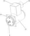
图1为本实施例所述机械隔离式双余度液压测速旋变传感器结构示意图;Fig. 1 is a structural schematic diagram of a mechanically isolated dual-redundancy hydraulic speed measuring resolver sensor described in this embodiment;
图2为本实施例所述机械隔离式双余度液压测速旋变传感器结构爆炸图;Fig. 2 is an exploded view of the structure of the mechanically isolated dual-redundancy hydraulic speed measuring resolver sensor described in this embodiment;
图3为本实施例所述机械隔离式双余度液压测速旋变传感器安装图;Fig. 3 is the installation diagram of the mechanically isolated dual-redundancy hydraulic speed measuring resolver sensor described in this embodiment;
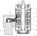
图4为本实施例所述机械隔离式双余度液压测速旋变传感器剖面图;Fig. 4 is a cross-sectional view of a mechanically isolated dual-redundancy hydraulic speed-measuring resolver sensor described in this embodiment;
其中,1-紧固螺钉;2-轴承端盖;3-轴承;4-花键转轴;5-转子组件;6-齿轮外壳;7-腔体;8-旋变定子;9-环变定子;10-定子支撑圈;11-压紧螺圈;12-外壳;13-凸台状安装法兰;14-航插安装座;15-连接器。Among them, 1-fastening screw; 2-bearing end cover; 3-bearing; 4-spline shaft; 5-rotor assembly; 6-gear shell; 7-cavity; 8-resolver stator; 9-ring variable stator ; 10-stator support ring; 11-compression coil; 12-housing; 13-boss-shaped mounting flange; 14-aviation plug mounting seat;
具体实施方式detailed description
下面通过附图及实施例对本发明所述机械隔离式双余度液压测速旋变传感器进行详细说明。The following is a detailed description of the mechanically isolated dual-redundancy hydraulic speed-measuring resolver sensor of the present invention with reference to the accompanying drawings and embodiments.
本公开实施例所述机械隔离式双余度液压测速旋变传感器,如图1、图2所示,包括腔体7、转子组件5和定子组件;所述腔体7的前端设置一凸台状安装法兰13;所述腔体7的内部设置一轴承孔;所述轴承孔位于腔体7的尾端;所述转子组件5的前端和尾端均设置一转轴;所述转子组件5设置于前述腔体7的内腔内部;所述转子组件5的前端和尾端均设置一轴承3;所述转子组件5通过前述转轴与轴承3相连接;位于所述转子组件5尾端的轴承3设置于前述轴承孔内,在提高轴承3稳定性的同时,通过腔体7底部的轴承孔实现对转子组件5一端的轴承3进行固定;所述转子组件5前端的转轴设置为花键转轴4;所述凸台状安装法兰13的前端固定设置有轴承端盖2;所述轴承端盖2上设置一通孔;前述花键转轴4前端从所述通孔内穿过位于腔体7外部;所述定子组件套设于前述腔体7外壁上。The mechanically isolated dual-redundancy hydraulic speed measuring resolver in the embodiment of the present disclosure, as shown in Figure 1 and Figure 2, includes a
在本公开实施例中,所述腔体7的尾端外壁上设置有螺纹;所述腔体7的尾端设置有压紧螺圈11;所述压紧螺圈11通过前述螺纹与腔体7相连接;所述压紧螺圈11与前述定子组件之间设置有定子支撑圈10。In the disclosed embodiment, the outer wall of the tail end of the
在本公开实施例中,所述转子组件5为双通道转子组件5;所述定子组件包括两个旋变定子8和两个环变定子9;前述两个环变定子9设置于前述两个旋变定子8之间;通过对转子组件5和定子组件的双余度设置,实现双余度输出,从而有效增大了信号冗余,提高了传感器的可靠性。In the embodiment of the present disclosure, the
在本公开实施例中,所述腔体7的外部设置有一外壳12;所述外壳12的侧壁上设置一开孔;所述外壳12的侧壁上与前述开孔对应的位置处设置有航插安装座14;所述航插安装座14的一侧设置有连接器15;所述外壳12的前端侧壁上与前述凸台状安装法兰13的侧壁上均对应设置有螺纹孔;所述外壳12与前述腔体7通过螺钉经前述螺纹孔相连接。将连接器15与前述外壳12内的定子组件通过线路相连接,通过连接器15与外部数据采集设备相连接,实现传感器监测数据的传输。In the embodiment of the present disclosure, a
本公开实施例所述机械隔离式双余度液压测速旋变传感器在进行组装时,将位于转子组件5尾端的轴承3装入腔体7底部的轴承孔内;将花键转轴4和双通道转子组件5的组合体装入腔体7中。When assembling the mechanically isolated dual-redundancy hydraulic speed measuring resolver described in the embodiment of the present disclosure, the
然后将位于转子组件5前端的轴承3装入轴承端盖2中,将轴承端盖2中心通孔穿过花键转轴4并压入腔体7内,用紧固螺钉1连接轴承端盖2和腔体7;再按照旋变定子8、环变定子9、环变定子9、旋变定子8的排列顺序将定子组件依次套设在腔体7外壁上。Then install the
接着将定子支撑圈10套在腔体7外壁上,然后用压紧螺圈11拧在腔体7尾部的螺纹上;再将航插安装座14与外壳12通过激光焊接,外壳12上的开孔朝向航插安装座14底部。将焊接好的外壳12,航插安装座14设置于腔体7外面,再用螺钉将其连接。Then the
最后,将旋变定子8,环变定子9的引出线通过外壳12出线孔与圆形连接器15插针对焊接,最后用紧固螺钉1把圆形连接器15固定在航插安装座14上。Finally, the lead-out wires of the
在本公开实施例中,腔体7采用非磁性材料,对于产品磁路阻隔较小。因磁阻增大,输出减小的部分,在具体应用中可通过后续电路部分的补偿得到提升。在腔体7设计时进行充分的计算,其耐压的安全余度可大大提高。In the embodiment of the present disclosure, the
在本公开实施例中,所述定子组件、转子组件5均布有线圈,因转子部分需长期接触液压油,定子部分已经因为腔体7的存在而与液压油隔绝,所以在本实施例中仅需对转子部分进行灌封。如需提高定子线圈组的抗老化和氧化性能,可使用环氧灌封胶对定子线圈进行灌封设计,以达到防潮、防水、防尘,耐湿热和大气老化和氧化。In the embodiment of the present disclosure, the stator assembly and the
在本公开实施例中,转子绕组采用导热灌封,达到C级绝缘要求。将旋变定子8、环变定子9分别进行灌封,旋变转子和环变转子组合灌封。灌封完成后,剔除溢胶即可直接进行装配。In the embodiment of the present disclosure, the rotor winding is potted with heat conduction, which meets the requirement of Class C insulation. The
使用时,如图3、图4所示通过花键转轴4与液压齿轮泵联接,传感器壳体与齿轮外壳6联接,齿轮泵内充满航空液压油,液压油可沿着轴系进入内部,但不会发生泄露。齿轮泵转动带动花键转轴4转动,从而带动转子转动,经圆形连接器15通过对定子组件输出的正余弦电压信号解析可判断液压齿轮泵的转速及方向。本实施例所述机械隔离式双余度液压测速旋变传感器的旋变输出角度可达到15′以内角度偏差,同时达到1万转/min以上的转速周期变化,并实现输出的精细控制,通过分体式结构可实现长期不间断的5MPa以上的耐压环境工作。When in use, as shown in Figure 3 and Figure 4, the
Claims (5)
Priority Applications (1)
| Application Number | Priority Date | Filing Date | Title |
|---|---|---|---|
| CN202211199148.3ACN115480072A (en) | 2022-09-29 | 2022-09-29 | Mechanical isolation type dual-redundancy hydraulic speed measurement rotary transformer sensor |
Applications Claiming Priority (1)
| Application Number | Priority Date | Filing Date | Title |
|---|---|---|---|
| CN202211199148.3ACN115480072A (en) | 2022-09-29 | 2022-09-29 | Mechanical isolation type dual-redundancy hydraulic speed measurement rotary transformer sensor |
Publications (1)
| Publication Number | Publication Date |
|---|---|
| CN115480072Atrue CN115480072A (en) | 2022-12-16 |
Family
ID=84393680
Family Applications (1)
| Application Number | Title | Priority Date | Filing Date |
|---|---|---|---|
| CN202211199148.3APendingCN115480072A (en) | 2022-09-29 | 2022-09-29 | Mechanical isolation type dual-redundancy hydraulic speed measurement rotary transformer sensor |
Country Status (1)
| Country | Link |
|---|---|
| CN (1) | CN115480072A (en) |
Cited By (1)
| Publication number | Priority date | Publication date | Assignee | Title |
|---|---|---|---|---|
| CN116111800A (en)* | 2022-12-30 | 2023-05-12 | 陕西东方航空仪表有限责任公司 | A Sealed Pressure Controllable Double Redundancy Rotary Transformer |
Citations (6)
| Publication number | Priority date | Publication date | Assignee | Title |
|---|---|---|---|---|
| JP2007189866A (en)* | 2006-01-16 | 2007-07-26 | Mitsubishi Electric Corp | Rotating electric machine and resolver |
| CN101545917A (en)* | 2009-05-07 | 2009-09-30 | 哈尔滨工业大学 | Sensor for measuring relative rotating speed of two concentric rotating shafts of double-rotor motor |
| CN208461655U (en)* | 2018-04-17 | 2019-02-01 | 苏州工业园区代尔塔电机技术有限公司 | A kind of induction type rotary transformer |
| CN110601451A (en)* | 2019-09-18 | 2019-12-20 | 精进电动科技股份有限公司 | Engine and motor assembly |
| CN214506845U (en)* | 2020-12-28 | 2021-10-26 | 陕西东方航空仪表有限责任公司 | Series non-contact double-redundancy sine and cosine rotary transformer |
| CN218412583U (en)* | 2022-09-29 | 2023-01-31 | 西安旭彤电子科技股份有限公司 | Mechanical isolation type dual-redundancy hydraulic speed measurement rotary transformer sensor |
- 2022
- 2022-09-29CNCN202211199148.3Apatent/CN115480072A/enactivePending
Patent Citations (6)
| Publication number | Priority date | Publication date | Assignee | Title |
|---|---|---|---|---|
| JP2007189866A (en)* | 2006-01-16 | 2007-07-26 | Mitsubishi Electric Corp | Rotating electric machine and resolver |
| CN101545917A (en)* | 2009-05-07 | 2009-09-30 | 哈尔滨工业大学 | Sensor for measuring relative rotating speed of two concentric rotating shafts of double-rotor motor |
| CN208461655U (en)* | 2018-04-17 | 2019-02-01 | 苏州工业园区代尔塔电机技术有限公司 | A kind of induction type rotary transformer |
| CN110601451A (en)* | 2019-09-18 | 2019-12-20 | 精进电动科技股份有限公司 | Engine and motor assembly |
| CN214506845U (en)* | 2020-12-28 | 2021-10-26 | 陕西东方航空仪表有限责任公司 | Series non-contact double-redundancy sine and cosine rotary transformer |
| CN218412583U (en)* | 2022-09-29 | 2023-01-31 | 西安旭彤电子科技股份有限公司 | Mechanical isolation type dual-redundancy hydraulic speed measurement rotary transformer sensor |
Cited By (1)
| Publication number | Priority date | Publication date | Assignee | Title |
|---|---|---|---|---|
| CN116111800A (en)* | 2022-12-30 | 2023-05-12 | 陕西东方航空仪表有限责任公司 | A Sealed Pressure Controllable Double Redundancy Rotary Transformer |
Similar Documents
| Publication | Publication Date | Title |
|---|---|---|
| EP4048487B1 (en) | Mechanical arm joint | |
| CN204719065U (en) | A kind of water proof type speed pickup | |
| CN107222078B (en) | Outer rotor permanent magnet direct-drive servo motor | |
| CN106347618B (en) | Underwater airscrew propulsion unit | |
| CN115480072A (en) | Mechanical isolation type dual-redundancy hydraulic speed measurement rotary transformer sensor | |
| CN218412583U (en) | Mechanical isolation type dual-redundancy hydraulic speed measurement rotary transformer sensor | |
| CN202067658U (en) | Rotary transformer | |
| CN104600936A (en) | Novel permanent-magnet synchronous servo motor | |
| CN111140636B (en) | A swing type solar windsurfing board drive mechanism | |
| CN109163839A (en) | A kind of brake performance testing device and test method | |
| CN107994717A (en) | A kind of integrated under-water DC brushless electric machine of magnetic shaft coupling | |
| CN210867471U (en) | Motor structure with rotary transformer | |
| CN207819692U (en) | A kind of servo wheel hub motor | |
| CN111585400B (en) | Servo motor and assembling method thereof | |
| CN113799169A (en) | Double-encoder joint module | |
| CN110429737B (en) | Double-rotation variable three-end cover variable pitch motor | |
| CN110518726B (en) | Direct-drive motor | |
| CN218412582U (en) | Dual-redundancy hydraulic speed-measuring rotary transformer sensor | |
| CN219227340U (en) | Outlet Connector and Servo Motor | |
| CN214480074U (en) | Tangential magnetizing assembling type outer rotor permanent magnet synchronous motor mounting structure | |
| CN113922561B (en) | Miniature motor | |
| CN204030785U (en) | Servomotor dedicated brake and servomotor | |
| CN211778960U (en) | Waterproof rubber ring and miniature server | |
| CN219322254U (en) | Novel servo motor structure | |
| CN110445416B (en) | Split type high-precision rotary traveling wave ultrasonic motor |
Legal Events
| Date | Code | Title | Description |
|---|---|---|---|
| PB01 | Publication | ||
| PB01 | Publication | ||
| SE01 | Entry into force of request for substantive examination | ||
| SE01 | Entry into force of request for substantive examination |