CN115473348A - Wireless charger - Google Patents
Wireless chargerDownload PDFInfo
- Publication number
- CN115473348A CN115473348ACN202211246787.0ACN202211246787ACN115473348ACN 115473348 ACN115473348 ACN 115473348ACN 202211246787 ACN202211246787 ACN 202211246787ACN 115473348 ACN115473348 ACN 115473348A
- Authority
- CN
- China
- Prior art keywords
- assembly
- positioning magnet
- wireless charging
- spacer
- magnetic pole
- Prior art date
- Legal status (The legal status is an assumption and is not a legal conclusion. Google has not performed a legal analysis and makes no representation as to the accuracy of the status listed.)
- Pending
Links
- 125000006850spacer groupChemical group0.000claimsabstractdescription59
- 230000000712assemblyEffects0.000claimsdescription7
- 238000000429assemblyMethods0.000claimsdescription7
- XEEYBQQBJWHFJM-UHFFFAOYSA-NIronChemical compound[Fe]XEEYBQQBJWHFJM-UHFFFAOYSA-N0.000claimsdescription6
- 239000003292glueSubstances0.000claimsdescription4
- 229910052742ironInorganic materials0.000claimsdescription3
- 238000000034methodMethods0.000description15
- 230000000694effectsEffects0.000description7
- 230000004308accommodationEffects0.000description3
- 239000012141concentrateSubstances0.000description1
- 238000010586diagramMethods0.000description1
- 238000005516engineering processMethods0.000description1
- 230000005389magnetismEffects0.000description1
- 239000000463materialSubstances0.000description1
- 230000008719thickeningEffects0.000description1
Images


Classifications
- H—ELECTRICITY
- H02—GENERATION; CONVERSION OR DISTRIBUTION OF ELECTRIC POWER
- H02J—CIRCUIT ARRANGEMENTS OR SYSTEMS FOR SUPPLYING OR DISTRIBUTING ELECTRIC POWER; SYSTEMS FOR STORING ELECTRIC ENERGY
- H02J50/00—Circuit arrangements or systems for wireless supply or distribution of electric power
- H02J50/005—Mechanical details of housing or structure aiming to accommodate the power transfer means, e.g. mechanical integration of coils, antennas or transducers into emitting or receiving devices
- H—ELECTRICITY
- H02—GENERATION; CONVERSION OR DISTRIBUTION OF ELECTRIC POWER
- H02J—CIRCUIT ARRANGEMENTS OR SYSTEMS FOR SUPPLYING OR DISTRIBUTING ELECTRIC POWER; SYSTEMS FOR STORING ELECTRIC ENERGY
- H02J50/00—Circuit arrangements or systems for wireless supply or distribution of electric power
- H02J50/10—Circuit arrangements or systems for wireless supply or distribution of electric power using inductive coupling
- H—ELECTRICITY
- H02—GENERATION; CONVERSION OR DISTRIBUTION OF ELECTRIC POWER
- H02J—CIRCUIT ARRANGEMENTS OR SYSTEMS FOR SUPPLYING OR DISTRIBUTING ELECTRIC POWER; SYSTEMS FOR STORING ELECTRIC ENERGY
- H02J50/00—Circuit arrangements or systems for wireless supply or distribution of electric power
- H02J50/70—Circuit arrangements or systems for wireless supply or distribution of electric power involving the reduction of electric, magnetic or electromagnetic leakage fields
- H—ELECTRICITY
- H02—GENERATION; CONVERSION OR DISTRIBUTION OF ELECTRIC POWER
- H02J—CIRCUIT ARRANGEMENTS OR SYSTEMS FOR SUPPLYING OR DISTRIBUTING ELECTRIC POWER; SYSTEMS FOR STORING ELECTRIC ENERGY
- H02J50/00—Circuit arrangements or systems for wireless supply or distribution of electric power
- H02J50/90—Circuit arrangements or systems for wireless supply or distribution of electric power involving detection or optimisation of position, e.g. alignment
- H—ELECTRICITY
- H02—GENERATION; CONVERSION OR DISTRIBUTION OF ELECTRIC POWER
- H02J—CIRCUIT ARRANGEMENTS OR SYSTEMS FOR SUPPLYING OR DISTRIBUTING ELECTRIC POWER; SYSTEMS FOR STORING ELECTRIC ENERGY
- H02J7/00—Circuit arrangements for charging or depolarising batteries or for supplying loads from batteries
- H02J7/0029—Circuit arrangements for charging or depolarising batteries or for supplying loads from batteries with safety or protection devices or circuits
- H—ELECTRICITY
- H02—GENERATION; CONVERSION OR DISTRIBUTION OF ELECTRIC POWER
- H02J—CIRCUIT ARRANGEMENTS OR SYSTEMS FOR SUPPLYING OR DISTRIBUTING ELECTRIC POWER; SYSTEMS FOR STORING ELECTRIC ENERGY
- H02J7/00—Circuit arrangements for charging or depolarising batteries or for supplying loads from batteries
- H02J7/0042—Circuit arrangements for charging or depolarising batteries or for supplying loads from batteries characterised by the mechanical construction
- H02J7/0044—Circuit arrangements for charging or depolarising batteries or for supplying loads from batteries characterised by the mechanical construction specially adapted for holding portable devices containing batteries
Landscapes
- Engineering & Computer Science (AREA)
- Power Engineering (AREA)
- Computer Networks & Wireless Communication (AREA)
- Physics & Mathematics (AREA)
- Electromagnetism (AREA)
- Charge And Discharge Circuits For Batteries Or The Like (AREA)
Abstract
Description
Translated fromChinese技术领域technical field
本申请涉及无线充电的技术领域,尤其涉及一种无线充电器。The present application relates to the technical field of wireless charging, in particular to a wireless charger.
背景技术Background technique
有关于目前手机充电技术来说,除了一般的有线连接充电的方式之外,现在大多都通过无线充电的方式进行充电,如此省去携带电线的需求。无线充电是通过充电装置内的充电线圈对应靠近于电子装置的接收线圈,如此不需要通过电线实际的接触连接,即可达到充电方式。然,但上述无线充电的方式需要将电子装置的接收线圈与充电装置内的充电线圈互相对应配合才可以达到良好的充电效果。现有方式有通过凹槽嵌合定位或磁吸定位等方式,凹槽嵌合的方式会导致电子装置的外尺寸大小受到限制,使用上相当不方便。又,磁吸固定的方式会因为磁铁位于冲电线圈周围,而影响到充电线圈的充电效率等问题。Regarding the current mobile phone charging technology, in addition to the general wired connection charging method, most of them are now charged through wireless charging, which saves the need to carry wires. In wireless charging, the charging coil in the charging device is correspondingly close to the receiving coil of the electronic device, so that charging can be achieved without actual contact and connection of wires. However, the above wireless charging method needs to match the receiving coil of the electronic device with the charging coil in the charging device to achieve a good charging effect. Existing methods include groove fitting positioning or magnetic attraction positioning, etc. The groove fitting method will cause the external size of the electronic device to be limited, which is quite inconvenient to use. In addition, the magnetic fixation method will affect the charging efficiency of the charging coil because the magnet is located around the charging coil.
发明内容Contents of the invention
本申请实施例提供一种无线充电器,其能够解决现有无线充电通过磁吸固定进行无线充电时,磁铁对于无线充电影响的问题。The embodiment of the present application provides a wireless charger, which can solve the problem of the influence of the magnet on the wireless charging when the wireless charging is fixed by magnetic attraction in the existing wireless charging.
为了解决上述技术问题,本申请是这样实现的:In order to solve the above-mentioned technical problems, the application is implemented as follows:
提供了一种无线充电器,包括:外壳、无线充电组件、定位磁铁组件与间隔组件。无线充电组件设置于外壳内,定位磁铁组件位于无线充电组件的周围,间隔组件设置于无线充电组件与定位磁铁组件之间。A wireless charger is provided, including: a shell, a wireless charging component, a positioning magnet component and a spacer component. The wireless charging assembly is arranged in the shell, the positioning magnet assembly is located around the wireless charging assembly, and the spacer assembly is arranged between the wireless charging assembly and the positioning magnet assembly.
在其中一个实施例中,间隔组件包括侧板与底板,底板设置于定位磁铁组件的底部,侧板设置于底板靠近无线充电组件的一侧。In one embodiment, the spacer assembly includes a side plate and a bottom plate, the bottom plate is disposed on the bottom of the positioning magnet assembly, and the side plate is disposed on a side of the bottom plate close to the wireless charging component.
在其中一个实施例中,侧板的高度高于定位磁铁组件相邻于无线充电组件的侧面高度的三分之一以上。In one embodiment, the height of the side plate is higher than one-third of the height of the side of the positioning magnet assembly adjacent to the wireless charging assembly.
在其中一个实施例中,间隔组件包括侧板与底板,底板设置于无线充电组件的底部,侧板设置于底板靠近定位磁铁组件的一侧。In one embodiment, the spacer assembly includes a side plate and a bottom plate, the bottom plate is disposed on the bottom of the wireless charging assembly, and the side plate is disposed on a side of the bottom plate close to the positioning magnet assembly.
在其中一个实施例中,侧板的高度高于无线充电组件相邻于定位磁铁组件的侧面高度的三分之一以上。In one embodiment, the height of the side plate is higher than one-third of the height of the side of the wireless charging assembly adjacent to the positioning magnet assembly.
在其中一个实施例中,间隔组件包括第一间隔件与第二间隔件,第一间隔件与第二间隔件位于无线充电组件与定位磁铁组件之间,第一间隔件设置于定位磁铁组件,第二间隔件设置于无线充电组件。In one embodiment, the spacer assembly includes a first spacer and a second spacer, the first spacer and the second spacer are located between the wireless charging assembly and the positioning magnet assembly, the first spacer is disposed on the positioning magnet assembly, The second spacer is disposed on the wireless charging assembly.
在其中一个实施例中,第一间隔件包括第一侧板与第一底板,第一底板设置于定位磁铁组件的底部,第一侧板设置于第一底板靠近无线充电组件的一侧;第二间隔件包括第二侧板与第二底板,第二底板设置于无线充电组件的底部,第二侧板设置于第二底板靠近定位磁铁组件的一侧。In one embodiment, the first spacer includes a first side plate and a first bottom plate, the first bottom plate is disposed on the bottom of the positioning magnet assembly, and the first side plate is disposed on a side of the first bottom plate close to the wireless charging component; The second spacer includes a second side plate and a second bottom plate, the second bottom plate is disposed on the bottom of the wireless charging assembly, and the second side plate is disposed on a side of the second bottom plate close to the positioning magnet assembly.
在其中一个实施例中,间隔组件的材质为铁。In one embodiment, the spacer component is made of iron.
在其中一个实施例中,定位磁铁组件包括第一定位磁铁与第二定位磁铁,第二定位磁铁位于第一定位磁铁的一侧,第一定位磁铁邻近于无线充电组件,第二定位磁铁远离无线充电组件,第一定位磁铁与第二定位磁铁之间通过粘胶固定。In one of the embodiments, the positioning magnet assembly includes a first positioning magnet and a second positioning magnet, the second positioning magnet is located on one side of the first positioning magnet, the first positioning magnet is adjacent to the wireless charging assembly, and the second positioning magnet is away from the wireless charging assembly. The charging assembly is fixed by glue between the first positioning magnet and the second positioning magnet.
在其中一个实施例中,第一定位磁铁的两端分别包括第一磁极与第二磁极,第一磁极朝向外壳的表面,第二磁极朝向外壳的内部,第二定位磁铁的两端分别包括第三磁极与第四磁极,第三磁极朝向外壳的表面,第四磁极朝向外壳的内部。In one of the embodiments, the two ends of the first positioning magnet respectively include a first magnetic pole and a second magnetic pole, the first magnetic pole faces the surface of the casing, the second magnetic pole faces the inside of the casing, and the two ends of the second positioning magnet respectively include a first magnetic pole and a second magnetic pole. Three magnetic poles and a fourth magnetic pole, the third magnetic pole faces the surface of the casing, and the fourth magnetic pole faces the inside of the casing.
在其中一个实施例中,第一磁极与第二磁极为相异磁极,第三磁极与第四磁极为相异磁极,第一磁极与第四磁极为相同磁极,第二磁极与第三磁极为相同磁极。In one of the embodiments, the first magnetic pole and the second magnetic pole are different magnetic poles, the third magnetic pole and the fourth magnetic pole are different magnetic poles, the first magnetic pole and the fourth magnetic pole are the same magnetic pole, and the second magnetic pole and the third magnetic pole are same pole.
在其中一个实施例中,定位磁铁组件为多个,多个定位磁铁组件排列于无线充电组件的周围。In one embodiment, there are multiple positioning magnet assemblies, and the multiple positioning magnet assemblies are arranged around the wireless charging assembly.
在其中一个实施例中,无线充电组件包括发射线圈与导磁载板,发射线圈设置于导磁载板上,发射线圈对应于外壳的表面。In one embodiment, the wireless charging assembly includes a transmitting coil and a magnetically permeable carrier, the transmitting coil is disposed on the magnetically permeable carrier, and the transmitting coil corresponds to the surface of the casing.
在其中一个实施例中,无线充电组件与定位磁铁组件相对应外壳的表面用于置放电子装置进行充电,电子装置包括装置接收线圈与装置定位磁铁,装置定位磁铁位于装置接收线圈的周围,装置接收线圈对应于无线充电组件的发射线圈,装置定位磁铁对应于定位磁铁组件。In one of the embodiments, the surface of the housing corresponding to the wireless charging component and the positioning magnet component is used to place the electronic device for charging. The electronic device includes a device receiving coil and a device positioning magnet. The device positioning magnet is located around the receiving coil of the device. The receiving coil corresponds to the transmitting coil of the wireless charging assembly, and the device positioning magnet corresponds to the positioning magnet assembly.
在其中一个实施例中,外壳包括壳体与盖板,壳体具有容置槽,盖板封盖于容置槽的槽口,无线充电组件、定位磁铁组件与间隔组件设置于容置槽内,无线充电组件对应设置于盖板的位置,定位磁铁组件设置于容置槽的槽口周围。In one of the embodiments, the casing includes a housing and a cover plate, the housing has an accommodation slot, the cover plate covers the notch of the accommodation slot, and the wireless charging assembly, the positioning magnet assembly and the spacer assembly are arranged in the accommodation slot , the wireless charging assembly is arranged correspondingly at the position of the cover plate, and the positioning magnet assembly is arranged around the notch of the accommodating groove.
本申请提供一种无线充电器,其通过间隔组件分隔无线充电组件与定位磁铁组件之间,间隔组件可有效降低定位磁铁组件的磁力朝向无线充电组件的导磁载板溢散,如此能有效避免定位磁铁组件对于无线充电组件的磁场干扰,以提供良好的充电效果。The present application provides a wireless charger, which separates the wireless charging component and the positioning magnet component through a spacer component. The spacer component can effectively reduce the magnetic force of the positioning magnet component from spilling toward the magnetic carrier plate of the wireless charging component, which can effectively avoid The positioning magnet assembly interferes with the magnetic field of the wireless charging assembly to provide a good charging effect.
附图说明Description of drawings
此处所说明的附图用来提供对本申请的进一步理解,构成本申请的一部分,本申请的示意性实施例及其说明用于解释本申请,并不构成对本申请的不当限定。在附图中:The drawings described here are used to provide a further understanding of the application and constitute a part of the application. The schematic embodiments and descriptions of the application are used to explain the application and do not constitute an improper limitation to the application. In the attached picture:
图1是本申请的无线充电器的立体图。FIG. 1 is a perspective view of a wireless charger of the present application.
图2是图1的A-A’线的剖视图。Fig. 2 is a sectional view taken along line A-A' of Fig. 1 .
图3是本申请的无线充电器的分解图。Fig. 3 is an exploded view of the wireless charger of the present application.
图4是图2的第一实施方式的B区域放大图。FIG. 4 is an enlarged view of area B of the first embodiment in FIG. 2 .
图5是第二实施方式的区域放大图。Fig. 5 is an enlarged view of the area of the second embodiment.
图6是第三实施方式的区域放大图。Fig. 6 is an enlarged view of the area of the third embodiment.
图7是第四实施方式的区域放大图。Fig. 7 is an enlarged view of the area of the fourth embodiment.
结合附图说明如下:In conjunction with the accompanying drawings, the description is as follows:
1:无线充电器;11:外壳;111:壳体;1111:容置槽;112:盖板;13:无线充电组件;131:发射线圈;132:导磁载板;15:定位磁铁组件;151:第一定位磁铁;1511:第一磁极;1512:第二磁极;152:第二定位磁铁;1521:第三磁极;1522:第四磁极;17:间隔组件;171:侧板;172:底板;17A:第一间隔件;171A:第一侧板;172A:第一底板;17B:第二间隔件;171B:第二侧板;172B:第二底板;19:粘胶;2:电子装置;21:装置接收线圈;22:装置定位磁铁;221:第一装置定位磁极;222:第二装置定位磁极。1: wireless charger; 11: casing; 111: shell; 1111: storage tank; 112: cover plate; 13: wireless charging component; 131: transmitting coil; 132: magnetic carrier plate; 15: positioning magnet component; 151: the first positioning magnet; 1511: the first magnetic pole; 1512: the second magnetic pole; 152: the second positioning magnet; 1521: the third magnetic pole; 1522: the fourth magnetic pole; 17: spacer assembly; 171: side plate; 172: Bottom plate; 17A: first spacer; 171A: first side plate; 172A: first bottom plate; 17B: second spacer; 171B: second side plate; 172B: second bottom plate; 19: glue; 2: electronics device; 21: device receiving coil; 22: device positioning magnet; 221: first device positioning magnetic pole; 222: second device positioning magnetic pole.
具体实施方式detailed description
下面将结合本申请实施例中的附图,对本申请实施例中的技术方案进行清楚、完整地描述,显然,所描述的实施例是本申请一部分实施例,而不是全部的实施例。基于本申请中的实施例,本领域普通技术人员在没有作出创造性劳动前提下所获得的所有其他实施例,都属于本申请保护的范围。The following will clearly and completely describe the technical solutions in the embodiments of the present application with reference to the drawings in the embodiments of the present application. Obviously, the described embodiments are part of the embodiments of the present application, not all of them. Based on the embodiments in this application, all other embodiments obtained by persons of ordinary skill in the art without creative efforts fall within the protection scope of this application.
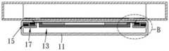
请参阅图1到图4,图1是本申请的无线充电器的立体图、图2是图1的A-A’线的剖视图、图3是本申请的无线充电器的分解图以及图4是图2的第一实施方式的A区域放大图。如图所示,本申请提供一种无线充电器1,包括:外壳11、无线充电组件13、定位磁铁组件15与间隔组件17。无线充电组件13设置于外壳11内。定位磁铁组件15位于无线充电组件13的周围。间隔组件17设置于无线充电组件13与定位磁铁组件15之间。如此间隔组件17将无线充电组件13与定位磁铁组件15分隔开来,其中,间隔组件17的材质为铁。Please refer to Figures 1 to 4, Figure 1 is a perspective view of the wireless charger of the present application, Figure 2 is a cross-sectional view of the line AA' of Figure 1, Figure 3 is an exploded view of the wireless charger of the present application, and Figure 4 is a An enlarged view of area A of the first embodiment in FIG. 2 . As shown in the figure, the present application provides a
请复参阅图2与图3于本实施方式中,外壳11包括壳体111与盖板112,壳体111具有容置槽1111,盖板112封盖于容置槽1111的槽口。无线充电组件13、定位磁铁组件15与间隔组件17设置于容置槽1111内,无线充电组件13对应设置于盖板112的位置。定位磁铁组件15设置于容置槽1111的槽口周围。间隔组件17包括侧板171与底板172,底板172设置于定位磁铁组件15的底部,侧板171设置于底板172靠近无线充电组件13的一侧。于本实施方式中,侧板171的高度高于定位磁铁组件15相邻于无线充电组件13的侧面高度的三分之一以上,侧板171可依据使用者的需求调整高度。Please refer to FIG. 2 and FIG. 3 again. In this embodiment, the
本实施方式的无线充电组件13包括发射线圈131与导磁载板132,发射线圈131设置于导磁载板132上,发射线圈131对应于外壳11的表面。其中,导磁载板132有助于发射线圈131的磁力线集中,以提高无线充电组件13的充电效率。然,用于定位电子装置2的定位磁铁组件15具有磁力,定位磁铁组件15的磁力会对于无线充电组件13的导磁载板132的磁性产生影响。本实施方式通过间隔组件17分隔无线充电组件13与定位磁铁组件15,间隔组件17可有效降低定位磁铁组件15的磁力朝向无线充电组件13的导磁载板132溢散,如此能有效避免定位磁铁组件15对于无线充电组件13的磁场干扰,造成无线充电组件13的充电效果受到影响。本实施方式通过间隔组件17能减少定位磁铁组件15的磁力对干无线充电组件13的充电过程的干扰,以提供良好的充电效果。The
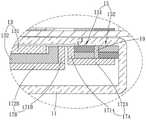
请复参阅图3,定位磁铁组件15包括第一定位磁铁151与第二定位磁铁152,第二定位磁铁152位于第一定位磁铁151的一侧,第一定位磁铁151邻近于无线充电组件13,第二定位磁铁152远离无线充电组件13,第一定位磁铁151与第二定位磁铁152之间通过粘胶19固定。又,第一定位磁铁151的两端分别包括第一磁极1511与第二磁极1512,第一磁极1511朝向外壳11的表面,第二磁极1512朝向外壳11的内部。第二定位磁铁152的两端分别包括第三磁极1521与第四磁极1522,第三磁极1521朝向外壳11的表面,第四磁极1522朝向外壳11的内部。其中,第一磁极1511与第二磁极1512为相异磁极,第三磁极1521与第四磁极1522为相异磁极,第一磁极1511与第四磁极1522为相同磁极,第二磁极1512与第三磁极1521为相同磁极。Please refer to FIG. 3 again. The
于本实施方式中,无线充电组件13与定位磁铁组件15相对应外壳11的表面用于置放电子装置2进行充电,电子装置2包括装置接收线圈21与装置定位磁铁22,装置定位磁铁22位于装置接收线圈21的周围,装置接收线圈21对应于无线充电组件13的发射线圈131,装置定位磁铁22对应于定位磁铁组件15。其中,装置定位磁铁22包括第一装置定位磁极221与第二装置定位磁极222,第一装置定位磁极221位于第二装置定位磁极222的内侧,第一装置定位磁极221对应于第一磁极1511,第二装置定位磁极222对应于第三磁极1521。于本实施方式中,第一磁极1511与第四磁极1522为S极,第二磁极1512与第三磁极1521为N极。而第一装置定位磁极221对应于第一磁极1511为N极,第二装置定位磁极222对应于第三磁极1521为S极。In this embodiment, the surface of the
另外,本实施方式并不限制定位磁铁组件15的数量或排列方式。若定位磁铁组件15为单个时,定位磁铁组件15为环形磁铁,并将无线充电组件13设置于定位磁铁组件15的中心处。若定位磁铁组件15为多个,多个定位磁铁组件15排列于无线充电组件13的周围。定位磁铁组件15可依据使用者的需求或装置结构的调整进行设置,本实施方式并不限制定位磁铁组件15的实施样式。In addition, this embodiment does not limit the number or arrangement of the
请参阅图5,其是第二实施方式的区域放大图。如图所示,本实施方式的图式以图3所规范的区域作为各个实施例差异的比较区域,本实施方式的其它元件结构皆与第一实施方式相同。本实施方式相较于第一实施方式的差异在于间隔组件17的设置位置。于本实施方式中,间隔组件17包括侧板171与底板172,底板172设置于无线充电组件13的底部,侧板171设置于底板172靠近定位磁铁组件15的一侧。其中,侧板171的高度高于无线充电组件13相邻于定位磁铁组件15的侧面高度的三分之一以上。本实施方式也可达到降低定位磁铁组件15的磁力影响无线充电组件13的效果。Please refer to FIG. 5 , which is an enlarged view of the area of the second embodiment. As shown in the figure, the diagram of this embodiment uses the area standardized in FIG. 3 as the comparison area for the differences of the various embodiments, and the structures of other components of this embodiment are the same as those of the first embodiment. The difference between this embodiment and the first embodiment lies in the arrangement position of the
请参阅图6,其是第三实施方式的区域放大图。如图所示,本实施方式相同第二实施方式的绘制方式。本实施方式相较于第一实施方式的差异在于间隔组件17的数量。于本实施方式中,间隔组件17包括第一间隔件17A与第二间隔件17B,第一间隔件17A与第二间隔件17B位于无线充电组件13与定位磁铁组件15之间,第一间隔件17A设置于定位磁铁组件15,第二间隔件17B设置于无线充电组件13。其中,第一间隔件17A包括第一侧板171A与第一底板172A,第一底板172A设置于定位磁铁组件15的底部,第一侧板171A设置于第一底板172A靠近无线充电组件13的一侧;第二间隔件17B包括第二侧板171B与第二底板172B,第二底板172B设置于无线充电组件13的底部,第二侧板171B设置于第二底板172B靠近定位磁铁组件15的一侧。如此间隔组件17分隔无线充电组件13与定位磁铁组件15的效果更好。Please refer to FIG. 6 , which is an enlarged view of the third embodiment. As shown in the figure, this embodiment is the same as the drawing method of the second embodiment. The difference between this embodiment and the first embodiment lies in the number of
请参阅图7,其是第四实施方式的区域放大图。如图所示,本实施方式相同第二实施方式的绘制方式。本实施方式相较于第一实施方式的差异在于间隔组件17的结构。于本实施方式中,间隔组件17包括侧板171与底板172,底板172设置于定位磁铁组件15的底部,侧板171设置于底板172靠近无线充电组件13的一侧。其中,侧板171的厚度填满无线充电组件13与定位磁铁组件15之间,换言之,本实施方式通过加厚侧板171的方式隔绝定位磁铁组件15朝向无线充电组件13的磁力影响。另外,本实施方式也可将无线充电组件13与定位磁铁组件15设置于侧板171两侧的方式以加强结构的整体强度。Please refer to FIG. 7 , which is an enlarged view of the area of the fourth embodiment. As shown in the figure, this embodiment is the same as the drawing method of the second embodiment. The difference between this embodiment and the first embodiment lies in the structure of the
综上所述,本申请提供一种无线充电器,其通过间隔组件分隔无线充电组件与定位磁铁组件之间,间隔组件可有效降低定位磁铁组件的磁力朝向无线充电组件的导磁载板溢散,如此能有效避免定位磁铁组件对于无线充电组件的磁场干扰,以提供良好的充电效果。To sum up, the present application provides a wireless charger, which separates the wireless charging component and the positioning magnet component through a spacer component, and the spacer component can effectively reduce the magnetic force of the positioning magnet component from spilling toward the magnetic carrier plate of the wireless charging component , so that the magnetic field interference of the positioning magnet assembly on the wireless charging assembly can be effectively avoided, so as to provide a good charging effect.
需要说明的是,在本文中,术语“包括”、“包含”或者其任何其他变体意在涵盖非排他性的包含,从而使得包括一系列要素的过程、方法、物品或者装置不仅包括那些要素,而且还包括没有明确列出的其他要素,或者是还包括为这种过程、方法、物品或者装置所固有的要素。在没有更多限制的情况下,由语句“包括一个……”限定的要素,并不排除在包括该要素的过程、方法、物品或者装置中还存在另外的相同要素。It should be noted that, in this document, the term "comprising", "comprising" or any other variation thereof is intended to cover a non-exclusive inclusion such that a process, method, article or apparatus comprising a set of elements includes not only those elements, It also includes other elements not expressly listed, or elements inherent in the process, method, article, or device. Without further limitations, an element defined by the phrase "comprising a ..." does not preclude the presence of additional identical elements in the process, method, article, or apparatus comprising that element.
上面结合附图对本申请的实施例进行了描述,但是本申请并不局限于上述的具体实施方式,上述的具体实施方式仅仅是示意性的,而不是限制性的,本领域的普通技术人员在本申请的启示下,在不脱离本申请宗旨和权利要求所保护的范围情况下,还可做出很多形式,均属于本申请的保护范围。The embodiments of the present application have been described above in conjunction with the accompanying drawings, but the present application is not limited to the above-mentioned specific implementations. The above-mentioned specific implementations are only illustrative and not restrictive. Those of ordinary skill in the art will Under the inspiration of the present application, without departing from the purpose of the application and the protection scope of the claims, many forms can also be made, all of which belong to the protection scope of the application.
Claims (15)
Priority Applications (3)
| Application Number | Priority Date | Filing Date | Title |
|---|---|---|---|
| CN202211246787.0ACN115473348A (en) | 2022-10-12 | 2022-10-12 | Wireless charger |
| US18/074,904US20240128802A1 (en) | 2022-10-12 | 2022-12-05 | Wireless charger |
| TW111151005ATWI863079B (en) | 2022-10-12 | 2022-12-30 | Wireless charger |
Applications Claiming Priority (1)
| Application Number | Priority Date | Filing Date | Title |
|---|---|---|---|
| CN202211246787.0ACN115473348A (en) | 2022-10-12 | 2022-10-12 | Wireless charger |
Publications (1)
| Publication Number | Publication Date |
|---|---|
| CN115473348Atrue CN115473348A (en) | 2022-12-13 |
Family
ID=84337710
Family Applications (1)
| Application Number | Title | Priority Date | Filing Date |
|---|---|---|---|
| CN202211246787.0APendingCN115473348A (en) | 2022-10-12 | 2022-10-12 | Wireless charger |
Country Status (3)
| Country | Link |
|---|---|
| US (1) | US20240128802A1 (en) |
| CN (1) | CN115473348A (en) |
| TW (1) | TWI863079B (en) |
Families Citing this family (2)
| Publication number | Priority date | Publication date | Assignee | Title |
|---|---|---|---|---|
| USD1077742S1 (en)* | 2022-05-27 | 2025-06-03 | Guangdong Mcdodo Industrial Company Limited | Wireless charger |
| USD1081562S1 (en)* | 2025-01-18 | 2025-07-01 | Yifeng Intelligent (Shenzhen) Co., Ltd. | Wireless charger |
Citations (7)
| Publication number | Priority date | Publication date | Assignee | Title |
|---|---|---|---|---|
| CN213937543U (en)* | 2020-11-10 | 2021-08-10 | 深圳市振端科技有限公司 | Charging module structure with wireless magnetic attraction |
| CN214314674U (en)* | 2021-03-15 | 2021-09-28 | 昆山联滔电子有限公司 | Wireless charging transmitter, wireless charging receiver and wireless charging device |
| CN216121938U (en)* | 2021-10-14 | 2022-03-22 | 广东桂荣永磁新材料科技有限公司 | Wireless receiving arrangement that charges is inhaled to modular magnetism |
| CN216290270U (en)* | 2021-11-02 | 2022-04-12 | 深圳市蓝禾科技有限公司 | Wireless charging device |
| WO2022104911A1 (en)* | 2020-11-23 | 2022-05-27 | 瑞声声学科技(深圳)有限公司 | Electronic device and wireless charging system |
| WO2022110483A1 (en)* | 2020-11-25 | 2022-06-02 | 深圳市倍力奇科技有限公司 | Magnetic attraction mechanism and wireless charging base |
| CN218352266U (en)* | 2022-10-12 | 2023-01-20 | 昆山联滔电子有限公司 | Wireless charger |
Family Cites Families (5)
| Publication number | Priority date | Publication date | Assignee | Title |
|---|---|---|---|---|
| US20060072302A1 (en)* | 2004-10-01 | 2006-04-06 | Chien Tseng L | Electro-luminescent (EL) illuminated wall plate device with push-tighten frame means |
| US8338990B2 (en)* | 2008-03-13 | 2012-12-25 | Access Business Group International Llc | Inductive power supply system with multiple coil primary |
| BR102018000122A2 (en)* | 2017-01-04 | 2018-07-24 | R Byrne Norman | portable power towers |
| CN110450666B (en)* | 2019-07-03 | 2020-10-20 | 广东电网有限责任公司肇庆德庆供电局 | Power transmission line inspection unmanned aerial vehicle charging supply device |
| US11557929B2 (en)* | 2020-01-06 | 2023-01-17 | Aira, Inc. | Device movement detection in a multi-coil charging surface |
- 2022
- 2022-10-12CNCN202211246787.0Apatent/CN115473348A/enactivePending
- 2022-12-05USUS18/074,904patent/US20240128802A1/enactivePending
- 2022-12-30TWTW111151005Apatent/TWI863079B/enactive
Patent Citations (7)
| Publication number | Priority date | Publication date | Assignee | Title |
|---|---|---|---|---|
| CN213937543U (en)* | 2020-11-10 | 2021-08-10 | 深圳市振端科技有限公司 | Charging module structure with wireless magnetic attraction |
| WO2022104911A1 (en)* | 2020-11-23 | 2022-05-27 | 瑞声声学科技(深圳)有限公司 | Electronic device and wireless charging system |
| WO2022110483A1 (en)* | 2020-11-25 | 2022-06-02 | 深圳市倍力奇科技有限公司 | Magnetic attraction mechanism and wireless charging base |
| CN214314674U (en)* | 2021-03-15 | 2021-09-28 | 昆山联滔电子有限公司 | Wireless charging transmitter, wireless charging receiver and wireless charging device |
| CN216121938U (en)* | 2021-10-14 | 2022-03-22 | 广东桂荣永磁新材料科技有限公司 | Wireless receiving arrangement that charges is inhaled to modular magnetism |
| CN216290270U (en)* | 2021-11-02 | 2022-04-12 | 深圳市蓝禾科技有限公司 | Wireless charging device |
| CN218352266U (en)* | 2022-10-12 | 2023-01-20 | 昆山联滔电子有限公司 | Wireless charger |
Also Published As
| Publication number | Publication date |
|---|---|
| TW202320452A (en) | 2023-05-16 |
| US20240128802A1 (en) | 2024-04-18 |
| TWI863079B (en) | 2024-11-21 |
Similar Documents
| Publication | Publication Date | Title |
|---|---|---|
| CN115473348A (en) | Wireless charger | |
| CN102411188B (en) | Lens Driving Device, Camera Capable Of Automatically Focusing And Mobile Terminal Having Photo Taking Function | |
| EP2007170B1 (en) | High efficient miniature electro-acoustic transducer with reduced dimensions | |
| KR102152541B1 (en) | Inductive module | |
| CN204886627U (en) | vibration motor | |
| CN204578771U (en) | Loud speaker | |
| CN105048760A (en) | Voice coil motor, coil block for voice coil motor, and method of manufacturing the coil block | |
| CN103117637A (en) | Voice coil motor | |
| WO2005017821A1 (en) | Reader/writer and mobile communication device | |
| JP5061202B2 (en) | Speaker magnetic flux collection system | |
| US9906866B2 (en) | Miniature speaker | |
| US10524032B1 (en) | Speaker box | |
| JP2012156279A (en) | Reception side non-contact charging module and reception side non-contact charging apparatus | |
| US20140056462A1 (en) | Electro-acoustic transducer | |
| CN117202042A (en) | Micro-speaker and acoustic device | |
| CN218352266U (en) | Wireless charger | |
| US9238252B2 (en) | Vibration sounder | |
| CN112615439B (en) | Wireless charging base, positioning cover, device, system and electronic equipment | |
| CN210724528U (en) | Multi-magnet square coil closed-loop motor | |
| KR102126135B1 (en) | Wireless charger for a terminal | |
| CN107223012A (en) | A kind of dual camera module and electronic equipment | |
| CN213937544U (en) | Wireless charging components, electronic equipment, wireless chargers and electronic equipment components | |
| JP3666692B2 (en) | Magnetic circuit for speakers | |
| KR102637779B1 (en) | Voice coil motor | |
| CN223022992U (en) | Magnetic unit, magnetic assembly, pairing assembly, electronic equipment and accessory and charging seat thereof |
Legal Events
| Date | Code | Title | Description |
|---|---|---|---|
| PB01 | Publication | ||
| PB01 | Publication | ||
| SE01 | Entry into force of request for substantive examination | ||
| SE01 | Entry into force of request for substantive examination |