CN115467509A - A new type of anti-drop support attached to the wall - Google Patents
A new type of anti-drop support attached to the wallDownload PDFInfo
- Publication number
- CN115467509A CN115467509ACN202211110437.1ACN202211110437ACN115467509ACN 115467509 ACN115467509 ACN 115467509ACN 202211110437 ACN202211110437 ACN 202211110437ACN 115467509 ACN115467509 ACN 115467509A
- Authority
- CN
- China
- Prior art keywords
- adjusting
- wall
- plate
- adjustment
- falling
- Prior art date
- Legal status (The legal status is an assumption and is not a legal conclusion. Google has not performed a legal analysis and makes no representation as to the accuracy of the status listed.)
- Pending
Links
Images

Classifications
- E—FIXED CONSTRUCTIONS
- E04—BUILDING
- E04G—SCAFFOLDING; FORMS; SHUTTERING; BUILDING IMPLEMENTS OR AIDS, OR THEIR USE; HANDLING BUILDING MATERIALS ON THE SITE; REPAIRING, BREAKING-UP OR OTHER WORK ON EXISTING BUILDINGS
- E04G5/00—Component parts or accessories for scaffolds
- E04G5/04—Means for fastening, supporting, or bracing scaffolds on or against building constructions
- E04G5/046—Means for fastening, supporting, or bracing scaffolds on or against building constructions for fastening scaffoldings on walls
- E—FIXED CONSTRUCTIONS
- E04—BUILDING
- E04G—SCAFFOLDING; FORMS; SHUTTERING; BUILDING IMPLEMENTS OR AIDS, OR THEIR USE; HANDLING BUILDING MATERIALS ON THE SITE; REPAIRING, BREAKING-UP OR OTHER WORK ON EXISTING BUILDINGS
- E04G3/00—Scaffolds essentially supported by building constructions, e.g. adjustable in height
- E04G3/28—Mobile scaffolds; Scaffolds with mobile platforms
Landscapes
- Engineering & Computer Science (AREA)
- Architecture (AREA)
- Mechanical Engineering (AREA)
- Civil Engineering (AREA)
- Structural Engineering (AREA)
- Movable Scaffolding (AREA)
Abstract
Translated fromChinese
Description
Translated fromChinese技术领域technical field
本发明涉及建筑设备技术领域,尤其涉及一种防坠型新型附墙支座。The invention relates to the technical field of construction equipment, in particular to a novel anti-drop support attached to a wall.
背景技术Background technique
现代社会中,建设高楼大厦时具有附着式升降脚手架,在升降脚手架搭建的过程中,为防止升降脚手架在使用的过程中出现脱落的现象,一般会在附墙支座上设有防止升降脚手架坠落的防坠装置,而现有的防坠装置方式一般为防坠摆块和触发摆块的联合作用,在脚手架发生坠落时,其脚手架的横杆触发摆块及时发生动作,并将力传递给防坠摆块,防坠摆块限制了导轨上的定位杆的活动以使得整个导轨停止动作,避免了坠落事故的发生,但在长时间的使用过程中,防坠装置容易出现失灵的现象,且现有的附墙支座为方便升降脚手架的升降,一般在固定脚手架的位置安装有滚动轮,但并未对滚动轮进行制动,导致升降脚手架在坠落的过程中滚动轮起到了辅助坠落的效果,加快脚手架的坠落。In modern society, when building high-rise buildings, there are attached lifting scaffolds. During the construction of lifting scaffolds, in order to prevent the lifting scaffolds from falling off during use, there are generally installations on the attached wall supports to prevent the lifting scaffolds from falling. The anti-falling device, and the existing anti-falling device method is generally the joint action of the anti-falling pendulum and the triggering pendulum. When the scaffold falls, the crossbar of the scaffold triggers the pendulum to move in time and transmits the force to the The anti-fall pendulum block, the anti-fall pendulum block restricts the movement of the positioning rod on the guide rail so that the entire guide rail stops moving, avoiding the occurrence of falling accidents, but during long-term use, the anti-fall device is prone to failure. Moreover, in order to facilitate the lifting of the lifting scaffold, the existing wall-attached support is generally equipped with a rolling wheel at the position of the fixed scaffold, but the rolling wheel is not braked, causing the rolling wheel to assist the falling of the lifting scaffold during the falling process. The effect of accelerating the fall of scaffolding.
因此,本方案特提出一种防坠型新型附墙支座,以解决上述问题。Therefore, this program proposes a new type of anti-drop type wall-attached support to solve the above problems.
发明内容Contents of the invention
本发明的主要目的在于提供一种防坠型新型附墙支座,旨在解决升降脚手架防坠的技术问题。The main purpose of the present invention is to provide a new type of anti-fall support attached to the wall, aiming to solve the technical problem of anti-fall of lifting scaffolding.
为达到所述目的,本发明的技术方案是这样实现的:一种防坠型新型附墙支座,包括安装组件、调节组件、防坠组件和防坠摆块,所述安装组件包括安装板和横梁板;In order to achieve the stated purpose, the technical solution of the present invention is achieved in the following way: a new type of anti-fall bracket attached to the wall, including an installation assembly, an adjustment assembly, an anti-fall assembly and an anti-fall pendulum block, and the installation assembly includes a mounting plate and beam panels;
所述调节组件包括双向调节丝杆和螺纹连接在双向调节丝杆外的两个调节板;The adjustment assembly includes a two-way adjustment screw rod and two adjustment plates threaded outside the two-way adjustment screw rod;
所述防坠组件包括固定连接在调节板一侧的固定架,所述固定架外套设有活动架,所述固定架和活动架的俯视均呈L型,所述固定架和活动架的相对面均开设有转动槽,所述转动槽内固定连接有转动杆,所述转动杆外以转动杆为轴心转动连接有转动轮,所述转动杆外周轴等距开设有若干个收纳槽,所述收纳槽的内壁转动连接有三角形转块,所述转动轮内开设有与三角形转块相适配的卡槽,所述三角形转块与收纳槽的相对面设置有抵紧弹簧。The anti-drop assembly includes a fixed frame fixedly connected to one side of the adjustment plate, and a movable frame is provided on the outer cover of the fixed frame, and the fixed frame and the movable frame are L-shaped in plan view, and the opposite sides of the fixed frame and the movable frame are Each surface is provided with a rotating groove, the rotating rod is fixedly connected to the rotating rod, and the rotating wheel is connected to the rotating rod with the rotating rod as the axis, and several receiving grooves are equidistantly arranged on the outer peripheral axis of the rotating rod. The inner wall of the storage tank is rotatably connected with a triangular turning block, the rotating wheel is provided with a card slot matching with the triangular turning block, and a spring is provided on the opposite surface of the triangular turning block and the storage tank.
进一步地,所述横梁板安装在安装板的侧面,所述安装板的侧面开设有腰型安装孔,所述防坠摆块设置在横梁板上,所述安装板与横梁板垂直设置,且所述安装板和横梁板之间设有加强板。Further, the beam plate is installed on the side of the mounting plate, the side of the mounting plate is provided with a waist-shaped installation hole, the anti-fall pendulum block is arranged on the beam plate, the mounting plate is vertically arranged to the beam plate, and A reinforcing plate is provided between the mounting plate and the beam plate.
进一步地,所述横梁板的侧面开设有调节槽,两个所述调节板滑动在调节槽的内部。Further, an adjustment slot is opened on the side of the beam plate, and the two adjustment plates slide inside the adjustment slot.
进一步地,两个所述调节板上下面均焊接有固定螺纹柱,所述横梁板的上下表面均开设有与固定螺纹柱相适配的腰型固定槽,且所述固定螺纹柱外螺纹连接有固定螺帽。Further, the upper and lower sides of the two adjustment plates are welded with fixed threaded columns, and the upper and lower surfaces of the beam plates are provided with waist-shaped fixing grooves that are compatible with the fixed threaded columns, and the fixed threaded columns are externally threaded. With fixing nut.
进一步地,所述固定架插入活动架内部的一侧开设有调节螺纹孔,所述调节螺纹孔的内壁螺纹连接有调节螺栓,且所述调节螺栓的螺帽端延伸出活动架的侧面并与活动架转动连接。Further, the side of the fixed frame inserted into the movable frame is provided with an adjustment threaded hole, the inner wall of the adjusted threaded hole is threaded with an adjusting bolt, and the nut end of the adjusting bolt extends out of the side of the movable frame and is connected to the movable frame. The movable frame is rotatably connected.
进一步地,所述转动轮的外周周向等距开设有若干个三角形防滑槽。Further, several triangular anti-skid grooves are equally spaced around the outer circumference of the rotating wheel.
本发明的有益效果体现在:通过安装组件便于将整个附墙支座安装在建筑的墙壁上,且通过调节组件能根据升降脚手架竖梁的形状进行调节,升降脚手架在使用的过程中,通过转动轮便于升降脚手架的上升,待升降脚手架固定后,三角形转块与卡槽配合,避免转动轮反转,对升降脚手架起到制动的作用,在防坠摆块失灵的情况下,能避免升降脚手架立刻出现下坠的现象,保证升降脚手架的正常使用。The beneficial effect of the present invention is embodied in that the entire wall-attached support can be easily installed on the wall of the building through the installation component, and can be adjusted according to the shape of the vertical beam of the lifting scaffold through the adjustment component. The wheel facilitates the lifting of the lifting scaffold. After the lifting scaffold is fixed, the triangular turning block cooperates with the card slot to prevent the rotating wheel from reversing and act as a brake on the lifting scaffold. In the case of failure of the anti-fall pendulum block, it can avoid lifting The scaffolding immediately appeared to fall, ensuring the normal use of the lifting scaffolding.
附图说明Description of drawings
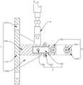
图1为本发明一实施例的正剖结构示意图;Fig. 1 is a schematic diagram of the front section structure of an embodiment of the present invention;
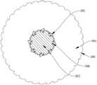
图2为本发明一实施例的转动轮正剖结构示意图;Fig. 2 is a schematic diagram of the front sectional structure of a rotating wheel according to an embodiment of the present invention;
图3为本发明一实施例的防坠组件立体结构示意图。Fig. 3 is a schematic diagram of the three-dimensional structure of the anti-drop assembly according to an embodiment of the present invention.
附图标记说明:Explanation of reference signs:
1、安装组件;101、安装板;102、横梁板;103、腰型安装孔;104、加强板;2、调节组件;201、双向调节丝杆;202、调节板;203、固定螺纹柱;204、固定螺帽;3、防坠组件;301、固定架;302、活动架;303、转动杆;304、转动轮;305、三角形转块;306、抵紧弹簧;307、调节螺栓;308、三角形防滑槽;4、防坠摆块。1. Installation component; 101. Installation plate; 102. Beam plate; 103. Waist-shaped installation hole; 104. Reinforcement plate; 2. Adjustment component; 201. Two-way adjustment screw; 202. Adjustment plate; 204, fixed nut; 3, anti-drop assembly; 301, fixed frame; 302, movable frame; 303, rotating rod; 304, rotating wheel; 305, triangular turning block; , Triangular anti-slip groove; 4, Anti-drop pendulum block.
具体实施方式detailed description
下面将结合本发明实施例中的附图,对本发明实施例中的技术方案进行清楚、完整地描述,显然,所描述的实施例仅仅是本发明的一部分实施例,而不是全部的实施例。在不冲突的情况下,本申请中的实施例及实施例中的特征可以相互组合。基于本发明中的实施例,本领域普通技术人员在没有作出创造性劳动前提下所获得的所有其他实施例,都属于本发明保护的范围。The following will clearly and completely describe the technical solutions in the embodiments of the present invention with reference to the accompanying drawings in the embodiments of the present invention. Obviously, the described embodiments are only part of the embodiments of the present invention, not all of them. In the case of no conflict, the embodiments in the present application and the features in the embodiments can be combined with each other. Based on the embodiments of the present invention, all other embodiments obtained by persons of ordinary skill in the art without creative efforts fall within the protection scope of the present invention.
参见图1至图3:一种防坠型新型附墙支座,包括安装组件1、调节组件2、防坠组件3和防坠摆块4,安装组件1包括安装板101和横梁板102;See Figures 1 to 3: a new type of anti-fall bracket attached to the wall, including an
调节组件2包括双向调节丝杆201和螺纹连接在双向调节丝杆201外的两个调节板202;The
防坠组件3包括固定连接在调节板202一侧的固定架301,固定架301外套设有活动架302,固定架301和活动架302的俯视均呈L型,固定架301和活动架302的相对面均开设有转动槽,转动槽内固定连接有转动杆303,转动杆303外以转动杆303为轴心转动连接有转动轮304,转动杆303外周轴等距开设有若干个收纳槽,收纳槽的内壁转动连接有三角形转块305,转动轮304内开设有与三角形转块305相适配的卡槽,三角形转块305与收纳槽的相对面设置有抵紧弹簧306。The anti-drop assembly 3 comprises a
本发明,通过安装组件1便于将整个附墙支座安装在建筑的墙壁上,且通过调节组件2能根据升降脚手架竖梁的形状进行调节,升降脚手架在使用的过程中,通过转动轮304便于升降脚手架的上升,待升降脚手架固定后,三角形转块305与卡槽配合,避免转动轮304反转,对升降脚手架起到制动的作用,在防坠摆块失灵的情况下,能避免升降脚手架立刻出现下坠的现象,保证升降脚手架的正常使用。In the present invention, it is convenient to install the entire wall-attached support on the wall of the building through the
在一实施例中,横梁板102安装在安装板101的侧面,安装板101的侧面开设有腰型安装孔103,防坠摆块4设置在横梁板102上,安装板101与横梁板102垂直设置,且安装板101和横梁板102之间设有加强板104,通过腰型安装孔103便于对整个附墙支架进行安装,通过加强板104增加整个附墙支架的承重能力。In one embodiment, the
在一实施例中,横梁板102的侧面开设有调节槽,两个调节板202滑动在调节槽的内部,调节槽对调节板202的滑动起到限位的作用。In one embodiment, the side of the
在一实施例中,两个调节板202上下面均焊接有固定螺纹柱203,横梁板102的上下表面均开设有与固定螺纹柱203相适配的腰型固定槽,且固定螺纹柱203外螺纹连接有固定螺帽204,通过固定螺纹柱203与固定螺帽204配合,便于对调节块进行紧固,避免在使用的过程中出现松弛的现象,影响升降脚手架的固定。In one embodiment, the upper and lower sides of the two
在一实施例中,固定架301插入活动架302内部的一侧开设有调节螺纹孔,调节螺纹孔的内壁螺纹连接有调节螺栓307,且调节螺栓307的螺帽端延伸出活动架302的侧面并与活动架302转动连接,通过调节螺栓,便于对固定架301和活动架302之间的松紧度进行调节,方便对升降脚手架进行拆装。In one embodiment, the side of the
在一实施例中,转动轮304的外周周向等距开设有若干个三角形防滑槽308,通过三角形防滑槽308,能在升降脚手架固定后对升降脚手架的竖梁进行卡紧,避免升降脚手架出现下坠的现象。In one embodiment, several triangular
以上仅为本发明的较佳实施例而已,并不用以限制本发明,凡在本发明的精神和原则之内,所作的任何修改、等同更换、改进等,均应包含在本发明的保护范围之内。The above are only preferred embodiments of the present invention, and are not intended to limit the present invention. Any modifications, equivalent replacements, improvements, etc. made within the spirit and principles of the present invention should be included in the protection scope of the present invention within.
Claims (6)
Priority Applications (1)
| Application Number | Priority Date | Filing Date | Title |
|---|---|---|---|
| CN202211110437.1ACN115467509A (en) | 2022-09-13 | 2022-09-13 | A new type of anti-drop support attached to the wall |
Applications Claiming Priority (1)
| Application Number | Priority Date | Filing Date | Title |
|---|---|---|---|
| CN202211110437.1ACN115467509A (en) | 2022-09-13 | 2022-09-13 | A new type of anti-drop support attached to the wall |
Publications (1)
| Publication Number | Publication Date |
|---|---|
| CN115467509Atrue CN115467509A (en) | 2022-12-13 |
Family
ID=84332843
Family Applications (1)
| Application Number | Title | Priority Date | Filing Date |
|---|---|---|---|
| CN202211110437.1APendingCN115467509A (en) | 2022-09-13 | 2022-09-13 | A new type of anti-drop support attached to the wall |
Country Status (1)
| Country | Link |
|---|---|
| CN (1) | CN115467509A (en) |
Citations (12)
| Publication number | Priority date | Publication date | Assignee | Title |
|---|---|---|---|---|
| JP2001227155A (en)* | 1999-12-06 | 2001-08-24 | Daisan Chubu:Kk | Temporary scaffold supporting bracket, temporary scaffold tread and temporary scaffold supporting structure |
| JP2019190263A (en)* | 2018-04-21 | 2019-10-31 | 有限会社ケンテックシステムズ | Work method for building outer surface |
| CN211114749U (en)* | 2020-04-22 | 2020-07-28 | 海南燕赵建筑工程有限公司 | Anti-overturning and anti-falling attached lifting scaffold |
| CN212249114U (en)* | 2020-05-18 | 2020-12-29 | 广西固华建筑科技有限公司 | An anti-tilt and anti-fall device attached to a lifting scaffold |
| CN112376883A (en)* | 2020-11-17 | 2021-02-19 | 浙江铠甲建筑科技有限公司 | Automatic climbing device for scaffold |
| CN112727054A (en)* | 2021-02-06 | 2021-04-30 | 黄维利 | Speed anti-falling device of integral lifting type climbing frame |
| CN214498358U (en)* | 2021-01-26 | 2021-10-26 | 甘肃中业兴晟建筑科技有限公司 | Attached lifting scaffold detachable wall-attached support |
| CN215055139U (en)* | 2020-12-31 | 2021-12-07 | 重庆拓达建设(集团)有限公司 | Anti-falling structure of wall-attached climbing scaffold |
| CN215275491U (en)* | 2021-04-29 | 2021-12-24 | 云南建源电力器材有限公司 | Anti-falling device for power transmission line iron tower |
| CN215407342U (en)* | 2021-08-06 | 2022-01-04 | 陕西中安智模建设工程有限公司 | Falling protector with reset spring type structure |
| CN215407326U (en)* | 2021-07-05 | 2022-01-04 | 安徽美安达智能装备有限公司 | Locking mechanism for intelligent climbing frame |
| CN216276805U (en)* | 2021-05-14 | 2022-04-12 | 中国建筑一局(集团)有限公司 | A guide assembly for climbing frame |
- 2022
- 2022-09-13CNCN202211110437.1Apatent/CN115467509A/enactivePending
Patent Citations (12)
| Publication number | Priority date | Publication date | Assignee | Title |
|---|---|---|---|---|
| JP2001227155A (en)* | 1999-12-06 | 2001-08-24 | Daisan Chubu:Kk | Temporary scaffold supporting bracket, temporary scaffold tread and temporary scaffold supporting structure |
| JP2019190263A (en)* | 2018-04-21 | 2019-10-31 | 有限会社ケンテックシステムズ | Work method for building outer surface |
| CN211114749U (en)* | 2020-04-22 | 2020-07-28 | 海南燕赵建筑工程有限公司 | Anti-overturning and anti-falling attached lifting scaffold |
| CN212249114U (en)* | 2020-05-18 | 2020-12-29 | 广西固华建筑科技有限公司 | An anti-tilt and anti-fall device attached to a lifting scaffold |
| CN112376883A (en)* | 2020-11-17 | 2021-02-19 | 浙江铠甲建筑科技有限公司 | Automatic climbing device for scaffold |
| CN215055139U (en)* | 2020-12-31 | 2021-12-07 | 重庆拓达建设(集团)有限公司 | Anti-falling structure of wall-attached climbing scaffold |
| CN214498358U (en)* | 2021-01-26 | 2021-10-26 | 甘肃中业兴晟建筑科技有限公司 | Attached lifting scaffold detachable wall-attached support |
| CN112727054A (en)* | 2021-02-06 | 2021-04-30 | 黄维利 | Speed anti-falling device of integral lifting type climbing frame |
| CN215275491U (en)* | 2021-04-29 | 2021-12-24 | 云南建源电力器材有限公司 | Anti-falling device for power transmission line iron tower |
| CN216276805U (en)* | 2021-05-14 | 2022-04-12 | 中国建筑一局(集团)有限公司 | A guide assembly for climbing frame |
| CN215407326U (en)* | 2021-07-05 | 2022-01-04 | 安徽美安达智能装备有限公司 | Locking mechanism for intelligent climbing frame |
| CN215407342U (en)* | 2021-08-06 | 2022-01-04 | 陕西中安智模建设工程有限公司 | Falling protector with reset spring type structure |
Non-Patent Citations (1)
| Title |
|---|
| 郭谆钦等主编: "《机械设计基础》", 31 January 2017, pages: 64 - 65* |
Similar Documents
| Publication | Publication Date | Title |
|---|---|---|
| CN212249114U (en) | An anti-tilt and anti-fall device attached to a lifting scaffold | |
| CN115467509A (en) | A new type of anti-drop support attached to the wall | |
| CN112780059B (en) | A new node structure used for installation of high-altitude flower rack hanging basket | |
| CN209494235U (en) | A device for installing vertical members of steel structures | |
| CN209277505U (en) | Shaped steel platform for construction | |
| CN208329573U (en) | The anti-bias anti-drop system of attachment type raise scaffold | |
| CN212027106U (en) | An adjustable top bracket with inclined plate buckle | |
| CN107269014B (en) | Hydraulic climbing formwork angle-variable protective net system | |
| CN221219819U (en) | Film factory building frame post reinforcing apparatus | |
| CN209494239U (en) | A steel structure column installation device | |
| CN219138070U (en) | Anti-drop reinforced structure of building curtain | |
| CN219138316U (en) | Climbing frame anti-falling wall attaching support | |
| CN201877736U (en) | Control cable laying device | |
| CN219281222U (en) | A construction bearing platform | |
| CN223018497U (en) | A closed door for civil air defense projects | |
| CN210396082U (en) | Attached wall support triple anti-falling system of attached lifting scaffold | |
| CN219909913U (en) | Novel heightening piece suitable for installation of secondary operation layer installation adhesion support at bay window position | |
| CN111851977A (en) | A new type of eccentric shaft gravity pendulum block anti-fall device for attached scaffolding | |
| CN214062051U (en) | Building curtain wall with anti-drop mechanism | |
| CN223164208U (en) | Cantilever scaffold for large-size window opening of residential building | |
| CN217500671U (en) | Two-sided side open pore structure of assembled trompil steel sheet shear force wall | |
| CN211397266U (en) | Civil air defense door leaf | |
| CN212105666U (en) | A kind of protective escape type campus security window | |
| CN218205840U (en) | Be applied to novel emergency support of large-scale steel construction | |
| CN219622241U (en) | Wall-attached support of attached lifting scaffold |
Legal Events
| Date | Code | Title | Description |
|---|---|---|---|
| PB01 | Publication | ||
| PB01 | Publication | ||
| SE01 | Entry into force of request for substantive examination | ||
| SE01 | Entry into force of request for substantive examination | ||
| RJ01 | Rejection of invention patent application after publication | ||
| RJ01 | Rejection of invention patent application after publication | Application publication date:20221213 |