CN115461828A - Metal shell capacitor - Google Patents
Metal shell capacitorDownload PDFInfo
- Publication number
- CN115461828A CN115461828ACN202180007151.8ACN202180007151ACN115461828ACN 115461828 ACN115461828 ACN 115461828ACN 202180007151 ACN202180007151 ACN 202180007151ACN 115461828 ACN115461828 ACN 115461828A
- Authority
- CN
- China
- Prior art keywords
- metal
- capacitor
- bus bar
- shell
- plastic
- Prior art date
- Legal status (The legal status is an assumption and is not a legal conclusion. Google has not performed a legal analysis and makes no representation as to the accuracy of the status listed.)
- Granted
Links
Images


Classifications
- H—ELECTRICITY
- H01—ELECTRIC ELEMENTS
- H01G—CAPACITORS; CAPACITORS, RECTIFIERS, DETECTORS, SWITCHING DEVICES, LIGHT-SENSITIVE OR TEMPERATURE-SENSITIVE DEVICES OF THE ELECTROLYTIC TYPE
- H01G4/00—Fixed capacitors; Processes of their manufacture
- H01G4/002—Details
- H01G4/224—Housing; Encapsulation
- H—ELECTRICITY
- H01—ELECTRIC ELEMENTS
- H01G—CAPACITORS; CAPACITORS, RECTIFIERS, DETECTORS, SWITCHING DEVICES, LIGHT-SENSITIVE OR TEMPERATURE-SENSITIVE DEVICES OF THE ELECTROLYTIC TYPE
- H01G4/00—Fixed capacitors; Processes of their manufacture
- H01G4/002—Details
- H01G4/228—Terminals
- H—ELECTRICITY
- H01—ELECTRIC ELEMENTS
- H01G—CAPACITORS; CAPACITORS, RECTIFIERS, DETECTORS, SWITCHING DEVICES, LIGHT-SENSITIVE OR TEMPERATURE-SENSITIVE DEVICES OF THE ELECTROLYTIC TYPE
- H01G4/00—Fixed capacitors; Processes of their manufacture
- H01G4/32—Wound capacitors
- H—ELECTRICITY
- H01—ELECTRIC ELEMENTS
- H01G—CAPACITORS; CAPACITORS, RECTIFIERS, DETECTORS, SWITCHING DEVICES, LIGHT-SENSITIVE OR TEMPERATURE-SENSITIVE DEVICES OF THE ELECTROLYTIC TYPE
- H01G4/00—Fixed capacitors; Processes of their manufacture
- H01G4/38—Multiple capacitors, i.e. structural combinations of fixed capacitors
Landscapes
- Engineering & Computer Science (AREA)
- Power Engineering (AREA)
- Manufacturing & Machinery (AREA)
- Microelectronics & Electronic Packaging (AREA)
- Fixed Capacitors And Capacitor Manufacturing Machines (AREA)
Abstract
Description
Translated fromChinese技术领域technical field
本发明涉及一种电容器,尤其涉及一种内部具备绝缘网状塑料垫片、外部为金属材质壳体的散热性能优异的金属壳体电容器及其制造方法。The invention relates to a capacitor, in particular to a metal shell capacitor with an insulating mesh plastic gasket inside and a metal shell outside with excellent heat dissipation performance and a manufacturing method thereof.
背景技术Background technique
薄膜电容器目前广泛用于各种工业领域,例如,电气设备用电容器、低压进相用电容器、逆变器用电容器、滤波器用电容器等。Film capacitors are currently widely used in various industrial fields, such as capacitors for electrical equipment, capacitors for low-voltage phase advance, capacitors for inverters, capacitors for filters, etc.
在这些电容器的制造中,作为介电质,使用聚酯(PET)树脂、聚丙烯(PP)树脂、聚萘二甲酸乙二醇酯(PEN)树脂、聚碳酸酯(PC)树脂、聚苯硫醚树脂等介电质薄膜(或者也称为塑料膜),作为电极,使用在介电质薄膜的一面或两面沉积锌、铝、铝合金或先沉积铝后再沉积锌的沉积膜。In the manufacture of these capacitors, polyester (PET) resin, polypropylene (PP) resin, polyethylene naphthalate (PEN) resin, polycarbonate (PC) resin, polyphenylene Dielectric films such as thioether resins (or also called plastic films) are used as electrodes, in which zinc, aluminum, aluminum alloy or aluminum is deposited first and then zinc is deposited on one or both sides of the dielectric film.
薄膜电容器是卷取两片构成一对的沉积膜而制造,为了将卷取后电容器器件的两面当作电极,在电容器器件的两面热喷涂(thermal spray)锌或锌合金以形成热喷涂面,将汇流条或电极引线或电极端子以点焊、锡焊等方式结合于该热喷涂面,然后插入于外部壳体,以环氧树脂或聚氨酯等绝缘体材料填充后固化,便可以制造成壳体模具型电容器。Film capacitors are manufactured by coiling two deposited films that form a pair. In order to use both sides of the coiled capacitor device as electrodes, thermal spray (thermal spray) zinc or zinc alloy on both sides of the capacitor device to form a thermal spray surface. The bus bar or electrode lead wire or electrode terminal is combined with the thermal sprayed surface by spot welding, soldering, etc., and then inserted into the outer shell, filled with epoxy resin or polyurethane and other insulator materials and cured, and then the shell can be manufactured Die type capacitors.
在电容器器件的汇流条、电极引线或电极端子处连接电源,此时,电流从在电容器器件侧面形成的热喷涂面向沉积膜的宽度方向流动。流入电容器器件的电流与沉积金属的面积成比例地流动,在沉积膜宽度方向上与热喷涂面靠近的沉积膜中有较多电流流动,相反,在远离热喷涂面的沉积膜中有相对较少电流流动。A power source is connected at the bus bar, electrode lead or electrode terminal of the capacitor device, and at this time, current flows in the width direction of the deposited film from the thermally sprayed surface formed on the side of the capacitor device. The current flowing into the capacitor device flows in proportion to the area of the deposited metal, and more current flows in the deposited film close to the thermal sprayed surface in the width direction of the deposited film, and relatively less in the deposited film far away from the thermal sprayed surface. Less current flows.
现有电容器壳体为塑料,在壳体与P/N极(P、N极总线连接于电容器内部器件金属表面而形成模块组成单元的P、N极)间没有绝缘耐压问题。The existing capacitor shell is made of plastic, and there is no insulation and withstand voltage problem between the shell and the P/N poles (the P, N poles are bus-connected to the metal surface of the capacitor internal device to form the P, N poles of the module unit).
当使用金属壳体时,电容器的金属(铝、铁、非铁金属)壳体与电容器P/N极(P、N极总线连接于电容器内部器件金属表面而形成模块组成单元的P、N极)间存在发生绝缘内压不良的问题。When using a metal shell, the metal (aluminum, iron, non-ferrous metal) shell of the capacitor and the P/N pole of the capacitor (P, N pole buses are connected to the metal surface of the internal device of the capacitor to form the P, N poles of the module components. ) There is a problem of poor insulation internal pressure.
发生绝缘不良的原因:将在电容器内部器件的金属表面连接P、N极总线的单元放入金属壳体并用环氧树脂或聚氨酯等成型剂成型后,在由金属壳体与电容器器件模块构成的P/N极间,绝缘距离偏向一侧,绝缘距离变短或接触,或者流入导电性异物,于是在由金属壳体与电容器模块构成的P/N极之间因绝缘能力下降而发生绝缘不良。Reasons for poor insulation: Put the unit connected to the P and N pole buses on the metal surface of the capacitor internal device into the metal case and mold it with a molding agent such as epoxy resin or polyurethane. Between the P/N poles, the insulation distance is biased to one side, the insulation distance is shortened or contacted, or conductive foreign matter flows in, so that poor insulation occurs between the P/N poles composed of the metal case and the capacitor module due to a decrease in the insulation capacity. .
发明内容Contents of the invention
技术问题technical problem
本发明旨在解决上述问题,提供了一种金属壳体电容器,它既可以保持金属壳体优异散热特性,又能够解决金属壳体与电容器P/N极之间发生短路的问题。The present invention aims to solve the above problems, and provides a capacitor with a metal shell, which can not only maintain the excellent heat dissipation characteristics of the metal shell, but also solve the problem of short circuit between the metal shell and the P/N pole of the capacitor.
本发明旨在提供一种金属壳体电容器,其塑料绝缘外壳以网状构成以便具有多个开放部,利用填充材料使金属外壳、塑料外壳及电容器模块(单元)之间相互结合,同时通过塑料绝缘外壳的绝缘间隙形成构件厚度,准确地保持金属外壳内侧面与电容器模块(单元)之间的间隔。The present invention aims to provide a metal shell capacitor, the plastic insulating shell of which is formed in a mesh shape so as to have a plurality of openings, and the metal shell, the plastic shell and the capacitor module (unit) are combined with each other by using a filling material, and at the same time, the plastic shell The insulating gap of the insulating case forms the thickness of the member, accurately maintaining the interval between the inner side of the metal case and the capacitor module (unit).
另外,本发明旨在提供一种金属壳体电容器,使构成塑料绝缘外壳绝缘间隙形成构件的直线构件以由厚部和薄部反复交替而形成错层空间的形态或脉冲波形状体现,在填充环氧树脂时完全填充,不形成气穴,即使在强振动下耐久性也优异,提高金属壳体与电容器P/N极间的绝缘耐压,不发生不良。In addition, the present invention aims to provide a metal case capacitor in which the linear member constituting the insulating gap forming member of the plastic insulating case is embodied in the form of a staggered space or pulse wave shape formed by repeated alternating thick and thin parts, and the filling The epoxy resin is completely filled without forming air pockets, and has excellent durability even under strong vibrations, and improves the insulation withstand voltage between the metal case and the P/N electrodes of the capacitor without causing defects.
技术方案Technical solutions
本发明提供了以下技术方案:一种金属壳体电容器,其特征在于,包括:电容器模块、金属材质外壳、塑料绝缘构件和填充材料;The present invention provides the following technical solutions: a capacitor with a metal shell, characterized in that it includes: a capacitor module, a metal shell, a plastic insulating member, and a filling material;
所述电容器模块由介电质薄膜卷取形成,两侧形成有导电性的热喷涂面,包含电容器器件、第一汇流条、第二汇流条、绝缘片;所述第一汇流条电连接于所述电容器器件的一侧热喷涂面,在露出侧具备第一接出端子;所述第二汇流条电连接于所述电容器器件的另一侧热喷涂面,在露出侧具备第二接出端子,所述绝缘片介于第一汇流条与第二汇流条之间,使重叠的区域绝缘;The capacitor module is formed by coiling a dielectric film, with conductive thermal spraying surfaces formed on both sides, including a capacitor device, a first bus bar, a second bus bar, and an insulating sheet; the first bus bar is electrically connected to One side of the thermal sprayed surface of the capacitor device is provided with a first terminal on the exposed side; the second bus bar is electrically connected to the thermal sprayed surface on the other side of the capacitor device, and a second terminal is provided on the exposed side. a terminal, the insulating sheet is interposed between the first bus bar and the second bus bar to insulate the overlapping area;
所述金属材质外壳具备供所述电容器模块内置的空间,由金属材质构成;The metal shell has a space for the capacitor module to be built in, and is made of metal;
所述塑料绝缘构件位于电容器模块与金属材质外壳之间,执行电容器模块与金属材质外壳之间的绝缘功能;The plastic insulating member is located between the capacitor module and the metal casing, and performs an insulation function between the capacitor module and the metal casing;
所述填充材料以胶或液体状填充到电容器模块与金属材质外壳之间的空间并固化。The filling material is filled into the space between the capacitor module and the metal case in glue or liquid state and cured.
在上述技术方案基础上所述塑料绝缘构件为塑料绝缘外壳,具有划分成多个的开放部并形成立体空间,同时具备开放部,所述开放部用于供填充材料渗透到位于形成空间轮廓的多个平面上的绝缘间隙形成构件,开放部的面积比率为对应面总面积的至少50%以上,所述塑料绝缘构件的厚度为1mm~10mm。On the basis of the above technical solution, the plastic insulating member is a plastic insulating shell, which has a plurality of openings that are divided into a three-dimensional space, and is equipped with an opening, and the opening is used for the filling material to penetrate into the space that forms the outline of the space. In the insulation gap forming member on the plurality of planes, the area ratio of the open portion is at least 50% or more of the total area of the corresponding surfaces, and the thickness of the plastic insulation member is 1 mm to 10 mm.
在上述技术方案基础上,所述塑料绝缘外壳为塑料外壳,具有划分为多个的开放部并形成立体空间,位于形成空间轮廓的多个平面上的绝缘间隙形成构件以网状配备。On the basis of the above technical solution, the plastic insulating casing is a plastic casing having a plurality of openings divided into a three-dimensional space, and the insulating gap forming members located on a plurality of planes forming the outline of the space are arranged in a network shape.
发明效果Invention effect
本发明实施例提供的一种金属壳体电容器,具有以下有益效果:A metal shell capacitor provided by an embodiment of the present invention has the following beneficial effects:
1、在保持金属壳体优异散热特性的同时,解决了金属壳体与电容器P/N极之间发生短路的问题;1. While maintaining the excellent heat dissipation characteristics of the metal shell, it solves the problem of short circuit between the metal shell and the P/N pole of the capacitor;
2、本发明提供一种的金属壳体电容器,其塑料绝缘外壳以网状构成以便具有多个开放部,填充材料通过开放部流入,因而金属与填充材料直接结合面积增大,粘合力提高,利用填充材料使金属外壳、塑料外壳及电容器模块(单元)之间相互结合,同时通过塑料绝缘外壳的绝缘间隙形成构件厚度,准确地保持金属外壳内侧面与电容器模块(单元)之间的间隔。2. The present invention provides a metal shell capacitor, the plastic insulating shell of which is formed in a mesh shape so as to have a plurality of openings, and the filling material flows in through the openings, so that the direct bonding area between the metal and the filling material is increased, and the adhesive force is improved , use the filling material to combine the metal shell, the plastic shell and the capacitor module (unit) with each other, and at the same time form the thickness of the component through the insulating gap of the plastic insulating shell, and accurately maintain the distance between the inner surface of the metal shell and the capacitor module (unit) .
3、本发明提供一种金属壳体电容器,使构成塑料绝缘外壳绝缘间隙形成构件的直线构件以由厚部和薄部反复交替而形成错层空间的形态或脉冲波形状体现,在填充环氧树脂时完全填充,不形成气穴,即使在强振动下耐久性也优异,提高金属壳体与电容器P/N极间的绝缘耐压,不发生不良。3. The present invention provides a metal case capacitor, in which the linear member constituting the insulating gap forming member of the plastic insulating shell is embodied in the shape of a staggered space or pulse wave shape formed by repeated alternating thick and thin parts, and filled with epoxy The resin is completely filled, no air pockets are formed, and the durability is excellent even under strong vibration, and the insulation withstand voltage between the metal case and the P/N pole of the capacitor is improved, and no failure occurs.
附图说明Description of drawings
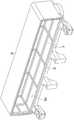
图1、图3是本发明一实施例的金属壳体电容器整体构成图;Fig. 1 and Fig. 3 are the overall construction diagrams of a metal case capacitor according to an embodiment of the present invention;
图2、图4是本发明一实施例的金属壳体电容器中的金属壳体和塑料绝缘外壳构成图;Fig. 2 and Fig. 4 are diagrams of the structure of the metal case and the plastic insulating case in the metal case capacitor according to an embodiment of the present invention;
图5是本发明一实施例的塑料绝缘外壳的直线构件实施例;Fig. 5 is an embodiment of a linear member of a plastic insulating casing according to an embodiment of the present invention;
图6是以往塑料壳体电容器发热测试试验结果;Fig. 6 is the test result of heat generation test of capacitors with plastic case in the past;
图7是本发明的金属壳体电容器发热测试试验结果。Fig. 7 is the test result of the heating test of the metal shell capacitor of the present invention.
最佳实施方式best practice
一种金属壳体电容器,其特征在于,包括:电容器模块10、金属材质外壳20、塑料绝缘构件和填充材料40;A metal case capacitor, characterized by comprising: a
所述电容器模块10由介电质薄膜卷取形成,两侧形成有导电性的热喷涂面,包含电容器器件C、第一汇流条1、第二汇流条2、绝缘片;所述第一汇流条1电连接于所述电容器器件C的一侧热喷涂面,在露出侧具备第一接出端子1a;所述第二汇流条2电连接于所述电容器器件C的另一侧热喷涂面,在露出侧具备第二接出端子2a,所述绝缘片介于第一汇流条1与第二汇流条2之间,使重叠的区域绝缘;The
所述金属材质外壳20具备供所述电容器模块10内置的空间,由金属材质构成;The
所述塑料绝缘构件位于电容器模块10与金属材质外壳20之间,执行电容器模块10与金属材质外壳20之间的绝缘功能;The plastic insulating member is located between the
所述填充材料40以胶或液体状填充到电容器模块10与金属材质外壳20之间的空间并固化。The filling
在本发明一实施例的一种金属壳体电容器中,优选所述塑料绝缘构件为塑料绝缘外壳30,具有划分成多个的开放部并形成立体空间,同时具备开放部,所述开放部用于供填充材料渗透到位于形成空间轮廓的多个平面上的绝缘间隙形成构件,开放部的面积比率为对应面总面积的至少50%以上,所述塑料绝缘构件的厚度为1mm~10mm。In a metal shell capacitor according to an embodiment of the present invention, preferably, the plastic insulating member is a plastic
在本发明一实施例的一种金属壳体电容器中,优选所述塑料绝缘外壳30为塑料外壳,具有划分为多个的开放部并形成立体空间,位于形成空间轮廓的多个平面上的绝缘间隙形成构件以网状配备。In a metal case capacitor according to an embodiment of the present invention, preferably, the plastic
具体实施方式detailed description
下面结合附图对本发明一实施例的金属壳体电容器作进一步说明:图1、图3是本发明一实施例的金属壳体电容器整体构成图,图2、图4是本发明一实施例的金属壳体电容器中的金属壳体和塑料绝缘外壳构成图,图5是本发明一实施例的塑料绝缘外壳的直线构件实施例。The metal case capacitor of an embodiment of the present invention will be further described below in conjunction with the accompanying drawings: Fig. 1 and Fig. 3 are the overall structure diagrams of a metal case capacitor according to an embodiment of the present invention, and Fig. 2 and Fig. 4 are diagrams of an embodiment of the present invention The configuration diagram of the metal case and the plastic insulating case in the metal case capacitor, Fig. 5 is an embodiment of the linear component of the plastic insulating case according to an embodiment of the present invention.
如图1至图5所示,一种金属壳体电容器,其特征在于,包括:电容器模块10、金属材质外壳20、塑料绝缘构件和填充材料40。As shown in FIGS. 1 to 5 , a metal shell capacitor is characterized by comprising: a
如图1和图3所示,所述电容器模块10由介电质薄膜卷取形成,两侧形成有导电性的热喷涂面,包含电容器器件C、第一汇流条1、第二汇流条2、绝缘片;所述第一汇流条1电连接于所述电容器器件C的一侧热喷涂面,在露出侧具备第一接出端子1a;所述第二汇流条2电连接于所述电容器器件C的另一侧热喷涂面,在露出侧具备第二接出端子2a,所述绝缘片介于第一汇流条1与第二汇流条2之间,使重叠的区域绝缘。所述金属材质外壳20具备供所述电容器模块10内置的空间,由金属材质构成。所述塑料绝缘构件位于电容器模块10与金属材质外壳20之间,执行电容器模块10与金属材质外壳20之间的绝缘功能。所述填充材料40以胶或液体状填充到电容器模块10与金属材质外壳20之间的空间并固化,所述填充材料40可以为环氧树脂或聚氨酯等。As shown in Figures 1 and 3, the
如图1至图4所示,优选的,所述塑料绝缘构件为塑料绝缘外壳30,具有划分成多个的开放部并形成立体空间,同时具备开放部,所述开放部用于供填充材料渗透到位于形成空间轮廓的多个平面上的绝缘间隙形成构件,开放部的面积比率为相应面全体面积的至少50%以上,所述塑料绝缘构件30的厚度为1mm~10mm。As shown in Figures 1 to 4, preferably, the plastic insulating member is a
如图2和图4所示,优选的,在一实施例中,塑料绝缘外壳30的外部轮廓以与金属材质外壳20内部轮廓相应的方式形成,塑料绝缘外壳30可以形成具有紧密插于金属材质外壳20内部面所需的最小限度的间隔。As shown in Figures 2 and 4, preferably, in one embodiment, the outer contour of the plastic insulating
在一实施例中,塑料绝缘外壳30的内部轮廓比电容器模块10的外部轮廓大1mm~2mm左右,在所述塑料绝缘外壳30的内部轮廓与电容器模块10外部轮廓之间存在1mm~2mm左右间隔,流动性优异的填充材料40填充于上述间隙中。In one embodiment, the inner contour of the plastic insulating
如图1所示,在一实施例中,塑料绝缘外壳30的内部侧壁(并非开口面和底面的四面侧壁、绝缘间隙形成构件32、33、34、35内部轮廓比电容器模块10的外部轮廓大1mm~2mm左右,因而投入开口部(上部开口部)的流动性优异的填充材料流入并填充于开口部(上部开口部)附近塑料绝缘外壳30的侧壁轮廓与电容器模块10外部轮廓之间存在的约1mm~2mm左右的隙缝之间。As shown in FIG. 1 , in one embodiment, the inner sidewalls of the plastic insulating case 30 (not the four sidewalls of the opening surface and the bottom surface, the inner contours of the insulating
优选的,塑料绝缘外壳30为塑料外壳,具有划分为多个的开放部并形成立体空间,位于形成空间轮廓的多个平面上的绝缘间隙形成构件以网状配备。Preferably, the plastic insulating
如图1至图4所示,优选的,所述金属材质外壳20形成大致六面体形空间,除了提供用于供填充材料填充的投入空间的第一开口部26之外的其余五个面封闭,塑料绝缘外壳30具有与所述金属材质外部壳体20内侧面相对应的轮廓,在所述第一开口部位置,在除第二开口部36之外的五个面配备有绝缘间隙形成构件31、32、33、34、35,位于形成空间轮廓的多个平面上的绝缘间隙形成构件以网状配备。As shown in FIGS. 1 to 4 , preferably, the
塑料绝缘外壳30通过划分成多个的开放部30a供填充材料渗透并固化,使塑料绝缘外壳30可以牢牢地固定于金属材质外部壳体20的内侧面。此时,绝缘间隙形成构件31、32、33、34、35发挥使电容器模块10与金属材质外部壳体20内侧面之间的间隔保持固定的功能。塑料的材质可以为PS、PET、PP、PPS、PBT、PC、ABS材质。The plastic insulating
<绝缘间隙形成构件为厚部和薄部反复交替的形态><The insulating gap forming member has a form in which the thick portion and the thin portion are alternately repeated>
如图2、图4、图5a所示,绝缘间隙构件31、32、33、34、35由塑料直线构件相互交叉构成网,形成一面开放的立体形状的网,As shown in Fig. 2, Fig. 4 and Fig. 5a, the insulating
所述塑料直线构件P是以厚部<厚的部位,P1>和薄部<薄的部位,P2>反复交替的形状配备,所述薄部的厚度t2小于所述厚部的厚度t1,The plastic linear member P is provided in the shape of thick part<thick part, P1> and thin part<thin part, P2>, the thickness t2 of the thin part is smaller than the thickness t1 of the thick part,
因此,当塑料绝缘外壳30和电容器模块10安放于金属材质外壳20内部时,与由所述薄部<薄的位置,P2>而形成的错层空间(P-开口1)相应,由于邻接第一开口部、第二开口部的绝缘间隙形成构件而变小的填充材料渗透空间进一步加大,使填充材料更容易渗透填充。Therefore, when the plastic insulating
通过测试结果可知,塑料直线构件P的厚部P1的厚度t1为2mm~5mm;薄部P2的厚度t2为0.7mm~4mm,这可以保持金属与电容器模块质之间既定的强度和间隙,而且填充材料投入性也优异。例如,构成绝缘间隙形成构件31、32、33、34、35的塑料直线构件P的厚部的厚度可以制作成横向面、纵向面均2.5mm,薄部为1.0mm的形态。According to the test results, the thickness t1 of the thick part P1 of the plastic linear member P is 2 mm to 5 mm; the thickness t2 of the thin part P2 is 0.7 mm to 4 mm, which can maintain the predetermined strength and gap between the metal and the capacitor module, and Filling material input is also excellent. For example, the thickness of the thick part of the plastic linear member P constituting the insulating
<绝缘间隙形成构件为脉冲波形态><Insulation gap forming member is pulse wave form>
如图2、图4、图5b所示,塑料绝缘外壳30的绝缘间隙形成构件31、32、33、34、35由塑料直线构件P相互交叉构成网,形成一面开放的立体形状的网,塑料直线构件P可以由脉冲波形状的直线构件形成,所述直线构件具有第三厚度t3,具有由弯曲与展开反复交替的整体上直线形轮廓。As shown in Figure 2, Figure 4, and Figure 5b, the insulating
塑料绝缘外壳30和电容器模块10安放于金属材质外部壳体20内部时,与在所述直线形轮廓上形成的反复形成空间(P-开口2)相应,由于邻接第一开口部、第二开口部的绝缘间隙形成构件而变小的填充材料渗透空间进一步加大,使填充材料容易渗透填充。When the plastic insulating
另外,当网状塑料绝缘外壳的绝缘间隙形成构件以脉冲波形态构成时,在填充环氧树脂时,环氧树脂完全填充,不形成气穴,提高金属壳体与电容器P/N极间的绝缘耐压,不发生不良。In addition, when the insulating gap forming member of the reticulated plastic insulating case is formed in the form of a pulse wave, when the epoxy resin is filled, the epoxy resin is completely filled, no air pockets are formed, and the contact between the metal case and the P/N pole of the capacitor is improved. Insulation withstand voltage, failure does not occur.
<露出侧绝缘构件><Exposed side insulating member>
如图1至图5所示,本发明的金属壳体电容器还包括:多个第一汇流条延伸部,所述第一汇流条延伸部在第一汇流条1上一体形成,在露出于金属材质外壳20或填充材料40外部的状态下,在第一汇流条延伸部末端形成有所述第一接出端子1a;第二汇流条延伸部,所述第二汇流条延伸部在所述第二汇流条2上一体形成,与所述第一汇流条延伸部重叠,在露出于金属材质外壳20或填充材料40外部的状态下,在第二汇流条延伸部末端形成有所述第二接出端子2a;其中,至少两个以上的第一汇流条延伸部和第二汇流条延伸部分别构成对并重叠,形成至少两个以上的延伸部结合体12;露出侧绝缘构件50,所述露出侧绝缘构件50用于所述电容器模块10的延伸部结合体12的非露出侧与所述金属材质外壳20的开口侧上边之间的绝缘;As shown in Figures 1 to 5, the metal shell capacitor of the present invention further includes: a plurality of first bus bar extensions, the first bus bar extensions are integrally formed on the first bus bar 1, and are exposed on the metal In the state outside the
优选的,露出侧绝缘构件50与所述塑料绝缘外壳30一体注塑成型,其用于所述电容器模块10的延伸部结合体12的非露出侧与金属材质外壳20的开口侧上边之间的绝缘。Preferably, the exposed-
如图3所示,在一实施例中,露出侧绝缘构件50形成至少有两种形式,可以为“┐状构件”或“匚状构件”,所述“┐状构件”由竖直条和水平部构成,所述竖直条与所埋设的塑料绝缘外壳(30)连接并向开口部侧向上延伸,所述水平部在所述竖直部的末端竖直折弯并接于金属材质外部壳体(20)的开口侧上边;所述“匚状构件”由竖直条、水平部和第二竖直部构成,所述竖直条与所埋设的塑料绝缘外壳(30)连接并向开口部侧向上延伸,所述水平部在所述竖直部末端竖直折弯并接于金属材质外部壳体(20)的开口侧上边,所述第二竖直部在水平部的末端再次向下折弯。As shown in FIG. 3 , in one embodiment, the exposed-
壳体形态的塑料绝缘构件(30)具有划分为多个的开放部并形成立体空间,与金属材质外壳(20)为分别生产;电容器模块(10)插入具有划分成多个开放部的并形成立体空间的塑料绝缘外壳(30);在电容器模块(10)和塑料绝缘外壳(30)插入金属材质外壳(20)后,投入填充材料(40)并使用模具进行固化,所述电容器模块(10)、塑料绝缘外壳(30)和金属材质外壳(20)固定成一体。The plastic insulating member (30) in the form of a shell has a plurality of openings and forms a three-dimensional space, and is produced separately from the metal casing (20); the capacitor module (10) is inserted into the opening and forms a plurality of openings. A plastic insulating shell (30) in a three-dimensional space; after the capacitor module (10) and the plastic insulating shell (30) are inserted into the metal material shell (20), the filling material (40) is dropped into and solidified using a mold, and the capacitor module (10 ), the plastic insulating shell (30) and the metal material shell (20) are fixed into one.
<散热效果><Cooling effect>
图6是以往塑料壳体电容器发热测试试验结果,图7是本发明的金属壳体电容器发热测试试验结果。Fig. 6 is the test result of the heat generation test of the conventional plastic case capacitor, and Fig. 7 is the heat generation test result of the metal case capacitor of the present invention.
在137A脉动电流、16KHz切换频率、85℃环境温度、65℃冷却水的条件下,在逆变器电路中测试的结果,如图6所示,塑料外壳(PPS)电容器组件中的最高温度可达94.7℃。如图7所示,在使用本发明的金属材质外壳的情况下,电容器组件中的最高温度为84.7℃。因此相比原有塑料(PPS)壳体,铝壳体电容器的散热特性优异,具有低约10℃的效果。(PPS壳体电容器温度上升94.7℃-铝电容器温度上升84.7℃=10℃)Under the conditions of 137A pulsating current, 16KHz switching frequency, 85°C ambient temperature, and 65°C cooling water, the test results in the inverter circuit, as shown in Figure 6, the highest temperature in the plastic case (PPS) capacitor assembly can be up to 94.7°C. As shown in FIG. 7, in the case of using the metal case of the present invention, the highest temperature in the capacitor assembly was 84.7°C. Therefore, compared with the conventional plastic (PPS) case, the heat dissipation characteristic of the aluminum case capacitor is excellent, and has the effect of lowering the temperature by about 10°C. (PPS shell capacitor temperature rise 94.7°C - aluminum capacitor temperature rise 84.7°C = 10°C)
PPS导热率与铝壳体导热率的比率为0.359:92Wm-1C-1。判断认为,壳体材质为铝时,导热率非常高,电容器内部散热效果大,铝壳体电容器温度上升试验中,发热非常低。由于使用铝壳体,因而△T低,约为10℃,因而电容器容量和体积可以如下所示减小。The ratio of PPS thermal conductivity to aluminum shell thermal conductivity is 0.359:92Wm-1 C-1 . It is judged that when the case material is aluminum, the thermal conductivity is very high, the heat dissipation effect inside the capacitor is large, and the heat generation of the aluminum case capacitor is very low in the temperature rise test. Since the aluminum case is used, ΔT is low, about 10°C, so the capacitor capacity and volume can be reduced as shown below.
【表1】【Table 1】

电容器容量减小25.2%,因此材料费成本减少25.2%,对外竞争力提高。体积减小19.1%,因而具有有利于封装设计的优点。汇流条材质为铜,因此铜的需要量减少约50%,具有节省成本效果。以往结构是在冷却散热器上排列IGBT,板条压住IGBT,在板条上贴上导热垫后,放上PPS壳体电容器进行组装。在使用金属壳体的情况下,在散热器上排列IGBT,将电容器壳体与铝外壳压合,变更为这种方式时,具有板条、导热垫和汇流条厚度变薄的优点,具有电容器容量减小且大量节约成本的效果。The capacity of the capacitor is reduced by 25.2%, so the material cost is reduced by 25.2%, and the external competitiveness is improved. The volume is reduced by 19.1%, thus having the advantage of facilitating package design. The material of the bus bar is copper, so the required amount of copper is reduced by about 50%, which has the effect of saving costs. In the conventional structure, the IGBTs are arranged on the cooling radiator, the IGBTs are pressed against the slats, the thermal pads are attached to the slats, and the capacitors in the PPS case are placed on the slabs for assembly. In the case of using a metal case, the IGBTs are arranged on the heat sink, and the capacitor case and the aluminum case are pressed together. When this method is changed, there is an advantage that the thickness of the strips, thermal pads and bus bars is thinner, and the capacitor The effect of capacity reduction and substantial cost savings.
本发明就上述提及的优选实施例进行了说明,但本发明的范围不限定于这种实施例,本发明的范围根据以下的权利要求书确定,可以包括属于与本发明均等范围的多样修订及变形。The present invention has been described with respect to the above-mentioned preferred embodiment, but the scope of the present invention is not limited to this embodiment, the scope of the present invention is determined according to the following claims, and can include various amendments belonging to the equal scope of the present invention and deformation.
需要指出的是,以下权利要求书记载的附图标记单纯用于帮助理解发明,不影响权利范围的解释,不得根据记载的附图标记而缩小解释权利范围。It should be pointed out that the reference signs recorded in the following claims are only used to help the understanding of the invention, and do not affect the interpretation of the scope of rights, and the interpretation of the scope of rights shall not be narrowed based on the recorded reference signs.
<工业实用性><Industrial applicability>
根据本发明,提供一种在金属外壳内部具有网状塑料绝缘外壳的金属壳体电容器,在保持金属壳体优异散热特性的同时,可以解决金属壳体与电容器P/N极间发生短路问题。According to the present invention, there is provided a metal shell capacitor with a mesh plastic insulating shell inside the metal shell, which can solve the problem of short circuit between the metal shell and capacitor P/N poles while maintaining the excellent heat dissipation characteristics of the metal shell.
另外,根据本发明,提供一种金属壳体电容器,其塑料绝缘外壳以网状构成以便具有多个开放部,由于通过开放部流入,因而金属与填充材料直接结合面积增大,粘合力提高,利用填充材料使金属外壳、塑料外壳及电容器模块(单元)之间相互结合,同时通过塑料绝缘外壳的绝缘间隙形成构件厚度,准确地保持金属外壳内侧面与电容器模块(单元)之间的间隔。In addition, according to the present invention, there is provided a metal case capacitor whose plastic insulating case is formed in a mesh shape so as to have a plurality of openings, and since the inflow through the openings increases the direct bonding area between the metal and the filling material and improves the adhesive force. , use the filling material to combine the metal shell, the plastic shell and the capacitor module (unit) with each other, and at the same time form the thickness of the component through the insulating gap of the plastic insulating shell, and accurately maintain the distance between the inner surface of the metal shell and the capacitor module (unit) .
另外,根据本发明,提供一种金属壳体电容器,使构成塑料绝缘外壳绝缘间隙形成构件的直线构件以由厚部和薄部反复交替而形成错层空间的形态或脉冲波形状体现,在填充环氧树脂时完全填充,不形成气穴,即使在强振动下耐久性也优异,提高金属壳体与电容器P/N极间的绝缘耐压,不发生不良。In addition, according to the present invention, there is provided a metal case capacitor, in which the linear member constituting the insulating gap forming member of the plastic insulating case is embodied in the form of alternate layer space or pulse wave shape formed by repeated alternate thick and thin portions, and the filling The epoxy resin is completely filled without forming air pockets, and has excellent durability even under strong vibrations, and improves the insulation withstand voltage between the metal case and the P/N electrodes of the capacitor without causing defects.
Claims (10)
Translated fromChineseApplications Claiming Priority (3)
| Application Number | Priority Date | Filing Date | Title |
|---|---|---|---|
| KR1020200147411AKR102331490B1 (en) | 2020-11-06 | 2020-11-06 | Metal Case Endurance Capacitor and Producing Method |
| KR10-2020-0147411 | 2020-11-06 | ||
| PCT/KR2021/008158WO2022097871A1 (en) | 2020-11-06 | 2021-06-29 | Metal case capacitor |
Publications (2)
| Publication Number | Publication Date |
|---|---|
| CN115461828Atrue CN115461828A (en) | 2022-12-09 |
| CN115461828B CN115461828B (en) | 2024-04-26 |
Family
ID=78899819
Family Applications (1)
| Application Number | Title | Priority Date | Filing Date |
|---|---|---|---|
| CN202180007151.8AActiveCN115461828B (en) | 2020-11-06 | 2021-06-29 | A metal shell capacitor |
Country Status (5)
| Country | Link |
|---|---|
| US (1) | US11929209B2 (en) |
| KR (1) | KR102331490B1 (en) |
| CN (1) | CN115461828B (en) |
| DE (1) | DE112021000480T5 (en) |
| WO (1) | WO2022097871A1 (en) |
Families Citing this family (3)
| Publication number | Priority date | Publication date | Assignee | Title |
|---|---|---|---|---|
| KR102332168B1 (en)* | 2020-12-10 | 2021-12-01 | (주)뉴인텍 | Case Molding Capacitor With Plastic PLastic Plate |
| KR102398737B1 (en)* | 2022-01-24 | 2022-05-17 | (주)뉴인텍 | Metal Case Molding Capacitor |
| CN115410822A (en)* | 2022-10-09 | 2022-11-29 | 宁国市裕华电器有限公司 | A Dry Type High Specific Energy Pulse Capacitor |
Citations (11)
| Publication number | Priority date | Publication date | Assignee | Title |
|---|---|---|---|---|
| JP2009038135A (en)* | 2007-07-31 | 2009-02-19 | Toyota Motor Corp | Capacitor device and manufacturing method thereof |
| CN102089839A (en)* | 2008-07-10 | 2011-06-08 | 松下电器产业株式会社 | Molded capacitor and its manufacturing method |
| KR20110101454A (en)* | 2010-03-08 | 2011-09-16 | 주식회사 뉴인텍 | Capacitor assembly |
| CN203895271U (en)* | 2014-02-04 | 2014-10-22 | 纽茵泰克株式会社 | Built-in housing capacitor |
| CN104319111A (en)* | 2014-11-05 | 2015-01-28 | 柯贝尔电能质量技术(上海)有限公司 | Supercapacitor module and method for manufacturing supercapacitor module |
| CN106098371A (en)* | 2016-06-27 | 2016-11-09 | 安徽赛福电子有限公司 | A kind of proof voltage long-service-life metal thin film capacitor |
| CN106415756A (en)* | 2014-05-28 | 2017-02-15 | 松下知识产权经营株式会社 | Film capacitor |
| KR20170034956A (en)* | 2015-09-21 | 2017-03-30 | 주식회사 뉴인텍 | Dual Material Case Capacitor |
| CN107240498A (en)* | 2017-07-25 | 2017-10-10 | 浙江七星电容器有限公司 | A kind of power reforming type Absorption Capacitance |
| CN208256482U (en)* | 2018-05-31 | 2018-12-18 | 安徽铜峰电子股份有限公司 | Integrated resinous fills self-healing damped capacitor |
| CN110993335A (en)* | 2019-11-22 | 2020-04-10 | 厦门法拉电子股份有限公司 | A kind of DC-Link film capacitor and its manufacturing method |
Family Cites Families (5)
| Publication number | Priority date | Publication date | Assignee | Title |
|---|---|---|---|---|
| JP5228581B2 (en)* | 2008-04-04 | 2013-07-03 | パナソニック株式会社 | Case mold type capacitor |
| KR101363285B1 (en)* | 2012-09-04 | 2014-02-17 | 주식회사 뉴인텍 | Low Inductance Case Mount Capacitors with Separate Unit Busbars |
| KR101436787B1 (en)* | 2013-12-31 | 2014-09-11 | 주식회사 뉴인텍 | Case Molding Type Low Inductance Condensor |
| KR102326063B1 (en)* | 2014-11-25 | 2021-11-12 | 현대모비스 주식회사 | Film capacitor module of inverter for vehicle |
| KR102572440B1 (en)* | 2017-12-12 | 2023-09-01 | 현대모비스 주식회사 | DC capacitors and discharge resistors of vehicle inverter |
- 2020
- 2020-11-06KRKR1020200147411Apatent/KR102331490B1/enactiveActive
- 2021
- 2021-06-29WOPCT/KR2021/008158patent/WO2022097871A1/ennot_activeCeased
- 2021-06-29USUS17/788,622patent/US11929209B2/enactiveActive
- 2021-06-29DEDE112021000480.8Tpatent/DE112021000480T5/enactivePending
- 2021-06-29CNCN202180007151.8Apatent/CN115461828B/enactiveActive
Patent Citations (11)
| Publication number | Priority date | Publication date | Assignee | Title |
|---|---|---|---|---|
| JP2009038135A (en)* | 2007-07-31 | 2009-02-19 | Toyota Motor Corp | Capacitor device and manufacturing method thereof |
| CN102089839A (en)* | 2008-07-10 | 2011-06-08 | 松下电器产业株式会社 | Molded capacitor and its manufacturing method |
| KR20110101454A (en)* | 2010-03-08 | 2011-09-16 | 주식회사 뉴인텍 | Capacitor assembly |
| CN203895271U (en)* | 2014-02-04 | 2014-10-22 | 纽茵泰克株式会社 | Built-in housing capacitor |
| CN106415756A (en)* | 2014-05-28 | 2017-02-15 | 松下知识产权经营株式会社 | Film capacitor |
| CN104319111A (en)* | 2014-11-05 | 2015-01-28 | 柯贝尔电能质量技术(上海)有限公司 | Supercapacitor module and method for manufacturing supercapacitor module |
| KR20170034956A (en)* | 2015-09-21 | 2017-03-30 | 주식회사 뉴인텍 | Dual Material Case Capacitor |
| CN106098371A (en)* | 2016-06-27 | 2016-11-09 | 安徽赛福电子有限公司 | A kind of proof voltage long-service-life metal thin film capacitor |
| CN107240498A (en)* | 2017-07-25 | 2017-10-10 | 浙江七星电容器有限公司 | A kind of power reforming type Absorption Capacitance |
| CN208256482U (en)* | 2018-05-31 | 2018-12-18 | 安徽铜峰电子股份有限公司 | Integrated resinous fills self-healing damped capacitor |
| CN110993335A (en)* | 2019-11-22 | 2020-04-10 | 厦门法拉电子股份有限公司 | A kind of DC-Link film capacitor and its manufacturing method |
Also Published As
| Publication number | Publication date |
|---|---|
| KR102331490B1 (en) | 2021-12-01 |
| CN115461828B (en) | 2024-04-26 |
| US20230039264A1 (en) | 2023-02-09 |
| US11929209B2 (en) | 2024-03-12 |
| DE112021000480T5 (en) | 2022-10-20 |
| WO2022097871A1 (en) | 2022-05-12 |
Similar Documents
| Publication | Publication Date | Title |
|---|---|---|
| CN115461828A (en) | Metal shell capacitor | |
| CN111373524B (en) | Power semiconductor device and method for manufacturing the same | |
| KR100576298B1 (en) | Resin molded device and apparatus for manufacturing same | |
| JP4027558B2 (en) | Power module | |
| KR100724227B1 (en) | Thin surface mounted type solid electrolytic capacitor | |
| JP5549491B2 (en) | Busbar module manufacturing method and busbar module | |
| CN105765716B (en) | Power semiconductor modular and composite module | |
| CN115053308B (en) | Capacitor with insert injection molding type metal plastic dual-material shell | |
| CN115088047B (en) | A case molded capacitor with improved filling surface levelness | |
| JP6841199B2 (en) | Semiconductor device | |
| JP6948855B2 (en) | Power semiconductor device and power conversion device using it | |
| CN111587528B (en) | Power semiconductor device | |
| US20180254235A1 (en) | Structure | |
| US20200279690A1 (en) | Capacitor | |
| CN115692398B (en) | Power module and electronic equipment with same | |
| JP6335815B2 (en) | Heat dissipation structure | |
| JP5906376B2 (en) | Case mold type capacitor | |
| CN103944354A (en) | Integrated power module packaging structure | |
| CN212113470U (en) | Adopt female metal casing film capacitor who arranges externally | |
| JP5945684B2 (en) | Case mold type capacitor | |
| JP5061693B2 (en) | Case mold type capacitor | |
| CN114334456A (en) | Thin film capacitor | |
| CN205845710U (en) | Chip high voltage ceramic capacitor | |
| WO2019021507A1 (en) | Semiconductor device and semiconductor module | |
| JP2023008579A (en) | capacitor |
Legal Events
| Date | Code | Title | Description |
|---|---|---|---|
| PB01 | Publication | ||
| PB01 | Publication | ||
| SE01 | Entry into force of request for substantive examination | ||
| SE01 | Entry into force of request for substantive examination | ||
| GR01 | Patent grant | ||
| GR01 | Patent grant |