CN115460088A - 5G power multi-service slice resource allocation and isolation method - Google Patents
5G power multi-service slice resource allocation and isolation methodDownload PDFInfo
- Publication number
- CN115460088A CN115460088ACN202210874625.5ACN202210874625ACN115460088ACN 115460088 ACN115460088 ACN 115460088ACN 202210874625 ACN202210874625 ACN 202210874625ACN 115460088 ACN115460088 ACN 115460088A
- Authority
- CN
- China
- Prior art keywords
- slice
- network
- resource
- isolation
- resources
- Prior art date
- Legal status (The legal status is an assumption and is not a legal conclusion. Google has not performed a legal analysis and makes no representation as to the accuracy of the status listed.)
- Pending
Links
Images


Classifications
- H—ELECTRICITY
- H04—ELECTRIC COMMUNICATION TECHNIQUE
- H04L—TRANSMISSION OF DIGITAL INFORMATION, e.g. TELEGRAPHIC COMMUNICATION
- H04L41/00—Arrangements for maintenance, administration or management of data switching networks, e.g. of packet switching networks
- H04L41/08—Configuration management of networks or network elements
- H04L41/0893—Assignment of logical groups to network elements
- G—PHYSICS
- G06—COMPUTING OR CALCULATING; COUNTING
- G06N—COMPUTING ARRANGEMENTS BASED ON SPECIFIC COMPUTATIONAL MODELS
- G06N3/00—Computing arrangements based on biological models
- G06N3/12—Computing arrangements based on biological models using genetic models
- G06N3/126—Evolutionary algorithms, e.g. genetic algorithms or genetic programming
- H—ELECTRICITY
- H04—ELECTRIC COMMUNICATION TECHNIQUE
- H04L—TRANSMISSION OF DIGITAL INFORMATION, e.g. TELEGRAPHIC COMMUNICATION
- H04L12/00—Data switching networks
- H04L12/28—Data switching networks characterised by path configuration, e.g. LAN [Local Area Networks] or WAN [Wide Area Networks]
- H04L12/46—Interconnection of networks
- H04L12/4641—Virtual LANs, VLANs, e.g. virtual private networks [VPN]
- H—ELECTRICITY
- H04—ELECTRIC COMMUNICATION TECHNIQUE
- H04L—TRANSMISSION OF DIGITAL INFORMATION, e.g. TELEGRAPHIC COMMUNICATION
- H04L41/00—Arrangements for maintenance, administration or management of data switching networks, e.g. of packet switching networks
- H04L41/08—Configuration management of networks or network elements
- H04L41/0803—Configuration setting
- H04L41/0823—Configuration setting characterised by the purposes of a change of settings, e.g. optimising configuration for enhancing reliability
- H04L41/0826—Configuration setting characterised by the purposes of a change of settings, e.g. optimising configuration for enhancing reliability for reduction of network costs
- H—ELECTRICITY
- H04—ELECTRIC COMMUNICATION TECHNIQUE
- H04L—TRANSMISSION OF DIGITAL INFORMATION, e.g. TELEGRAPHIC COMMUNICATION
- H04L41/00—Arrangements for maintenance, administration or management of data switching networks, e.g. of packet switching networks
- H04L41/08—Configuration management of networks or network elements
- H04L41/0896—Bandwidth or capacity management, i.e. automatically increasing or decreasing capacities
- H—ELECTRICITY
- H04—ELECTRIC COMMUNICATION TECHNIQUE
- H04L—TRANSMISSION OF DIGITAL INFORMATION, e.g. TELEGRAPHIC COMMUNICATION
- H04L41/00—Arrangements for maintenance, administration or management of data switching networks, e.g. of packet switching networks
- H04L41/16—Arrangements for maintenance, administration or management of data switching networks, e.g. of packet switching networks using machine learning or artificial intelligence
- H—ELECTRICITY
- H04—ELECTRIC COMMUNICATION TECHNIQUE
- H04L—TRANSMISSION OF DIGITAL INFORMATION, e.g. TELEGRAPHIC COMMUNICATION
- H04L41/00—Arrangements for maintenance, administration or management of data switching networks, e.g. of packet switching networks
- H04L41/50—Network service management, e.g. ensuring proper service fulfilment according to agreements
- H04L41/5041—Network service management, e.g. ensuring proper service fulfilment according to agreements characterised by the time relationship between creation and deployment of a service
- H04L41/5051—Service on demand, e.g. definition and deployment of services in real time
- H—ELECTRICITY
- H04—ELECTRIC COMMUNICATION TECHNIQUE
- H04W—WIRELESS COMMUNICATION NETWORKS
- H04W12/00—Security arrangements; Authentication; Protecting privacy or anonymity
- H04W12/30—Security of mobile devices; Security of mobile applications
- H—ELECTRICITY
- H04—ELECTRIC COMMUNICATION TECHNIQUE
- H04W—WIRELESS COMMUNICATION NETWORKS
- H04W16/00—Network planning, e.g. coverage or traffic planning tools; Network deployment, e.g. resource partitioning or cells structures
- H04W16/02—Resource partitioning among network components, e.g. reuse partitioning
- H04W16/10—Dynamic resource partitioning
- H—ELECTRICITY
- H04—ELECTRIC COMMUNICATION TECHNIQUE
- H04W—WIRELESS COMMUNICATION NETWORKS
- H04W4/00—Services specially adapted for wireless communication networks; Facilities therefor
- H04W4/50—Service provisioning or reconfiguring
Landscapes
- Engineering & Computer Science (AREA)
- Computer Networks & Wireless Communication (AREA)
- Signal Processing (AREA)
- Physics & Mathematics (AREA)
- Life Sciences & Earth Sciences (AREA)
- Health & Medical Sciences (AREA)
- Biophysics (AREA)
- Computer Security & Cryptography (AREA)
- Evolutionary Computation (AREA)
- Bioinformatics & Cheminformatics (AREA)
- Bioinformatics & Computational Biology (AREA)
- Evolutionary Biology (AREA)
- Theoretical Computer Science (AREA)
- Software Systems (AREA)
- Artificial Intelligence (AREA)
- Biomedical Technology (AREA)
- Data Mining & Analysis (AREA)
- Computational Linguistics (AREA)
- General Health & Medical Sciences (AREA)
- Molecular Biology (AREA)
- Computing Systems (AREA)
- General Engineering & Computer Science (AREA)
- General Physics & Mathematics (AREA)
- Mathematical Physics (AREA)
- Genetics & Genomics (AREA)
- Physiology (AREA)
- Computer Vision & Pattern Recognition (AREA)
- Databases & Information Systems (AREA)
- Medical Informatics (AREA)
- Data Exchanges In Wide-Area Networks (AREA)
Abstract
Translated fromChinese
Description
Translated fromChinese技术领域technical field
本发明属于基于5G的多业务切片与通道隔离技术领域,涉及一种面向5G电力多业务切片资源分配与隔离方法,尤其是一种基于SDN与NFV的面向5G电力多业务切片资源分配与隔离方法。The invention belongs to the technical field of 5G-based multi-service slicing and channel isolation, and relates to a method for allocating and isolating 5G power multi-service slice resources, in particular to a 5G power multi-service slice resource allocation and isolation method based on SDN and NFV .
背景技术Background technique
随着移动通信技术的蓬勃发展,人们的生活中也出现了各种各样的业务需求,为了适应这些需求,5G技术以一种新型的网络架构,提供了超高带宽、更低时延的连接。如今5G已经逐渐成为促进多业务需求发展的关键技术。一方面,它相对于之前的4G网络有更加灵活的特性;另一方面,它独特的定制性功能还可以满足各类垂直行业的需要,可用于解决多业务资源分配的需求。With the vigorous development of mobile communication technology, various business needs have emerged in people's lives. In order to meet these needs, 5G technology provides a new network architecture with ultra-high bandwidth and lower latency. connect. Today, 5G has gradually become a key technology to promote the development of multi-service requirements. On the one hand, it has more flexible features than the previous 4G network; on the other hand, its unique customization functions can also meet the needs of various vertical industries and can be used to solve the needs of multi-service resource allocation.
不同行业对网络的需求不同,针对多业务场景,5G网络可以根据业务需求构建的网络信道,并根据不同的业务需求和业务场景提供差异化的资源分配,可以更有效地满足多业务场景的多样化需求。当前在智能电网场景中,5G网络分片技术在资源分配方面的应用研究还处于发展阶段。在目前比较成熟的网络分片资源分配模型中,主要有基于连续域的、基于博弈论的和基于定价机制的分配模型,但上述传统的分配模型在实际应用中所产生的计算量过大,甚至会陷入局部最优,从而无法有效地提高算法性能。Different industries have different requirements for the network. For multi-service scenarios, 5G networks can build network channels according to business needs, and provide differentiated resource allocation according to different business needs and business scenarios, which can more effectively meet the diverse requirements of multi-service scenarios. demand. At present, in the smart grid scenario, the application research of 5G network slicing technology in resource allocation is still in the development stage. Among the relatively mature resource allocation models for network sharding, there are mainly allocation models based on continuous domain, game theory, and pricing mechanism. It may even fall into a local optimum, so that the performance of the algorithm cannot be effectively improved.
而面对能源互联网严峻的业务安全问题,深入研究基于5G的多业务切片技术与通道隔离技术是我们的迫切需求。5G网络切片分为eMBB切片、uRLLC切片、mMTC切片三大类,三类切片适合承载的电力业务有很大不同。网络切片的简单解释就是根据场景,在不同的场景需求下使用不同的网络,实现一个物理网络在逻辑层面的划分。网络切片可以完善网络资源配置,切片实例是网络功能与所需资源的集合,通过网络切片管理功能实现端到端切片的管理。Facing the serious business security issues of the Energy Internet, it is our urgent need to conduct in-depth research on 5G-based multi-service slicing technology and channel isolation technology. 5G network slicing is divided into three categories: eMBB slicing, uRLLC slicing, and mMTC slicing. The power services that the three types of slicing are suitable for carrying are very different. A simple explanation of network slicing is to use different networks in different scenarios according to different scenarios to realize the division of a physical network at the logical level. Network slicing can improve the configuration of network resources. A slicing instance is a collection of network functions and required resources. The end-to-end slicing management is realized through the network slicing management function.
网络切片是5G网络通信系统的基础结构,它能够按照业务基本需求灵活设定网络功能,但是在各切片运行期间,若切片之间隔离的安全性做的不好,也会产生相应的安全威胁,会严重影响网络安全。Network slicing is the basic structure of the 5G network communication system. It can flexibly set network functions according to the basic needs of the business. However, during the operation of each slice, if the security of isolation between slices is not done well, corresponding security threats will also occur. , will seriously affect network security.
在多业务网络的环境下,我们对需求响应的已经从传统的方式过渡到了多功能的综合需求响应。众多复杂业务的需求混合可能会引起资源之间的竞争关系,如果5G切片之间的隔离做的不好,切片之间可能会发生资源争夺,从而影响网络的正常部署和运行,严重会造成业务的瘫痪。In the environment of multi-service network, our demand response has transitioned from the traditional way to multi-functional comprehensive demand response. The mixing of requirements for many complex services may cause competition among resources. If the isolation between 5G slices is not done well, resource contention may occur between slices, which will affect the normal deployment and operation of the network, and seriously cause business problems. of paralysis.
良好的隔离技术还可以避免某一个切片的异常带来的不良影响,例如发生在内部的恶意攻击,隔离技术可以有效防止攻击大范围化、切片数据泄露等安全威胁。A good isolation technology can also avoid adverse effects caused by the abnormality of a certain slice, such as an internal malicious attack. The isolation technology can effectively prevent security threats such as large-scale attacks and slice data leakage.
现有的隔离技术大都只针对性能隔离需求或安全隔离需求,无法兼顾二者。当用户访问多个网络切片时,切片间的数据信息机密性可能受到攻击,可能造成网络或用户数据的泄露。Most of the existing isolation technologies only address performance isolation requirements or security isolation requirements, and cannot give consideration to both. When a user accesses multiple network slices, the confidentiality of data information between slices may be attacked, which may cause network or user data leakage.
经检索,未发现与本发明相同或相似的现有技术的专利文献。After searching, no patent documents of the prior art identical or similar to the present invention are found.
发明内容Contents of the invention
本发明的目的在于克服现有技术的不足,提出一种设计合理、业务安全性强且能够有效提升对切片资源的分配的基于SDN与NFV的面向5G电力多业务切片资源分配与隔离方法。The purpose of the present invention is to overcome the deficiencies of the existing technology, and propose a 5G power multi-service slice resource allocation and isolation method based on SDN and NFV, which is reasonable in design, strong in service security, and can effectively improve the allocation of slice resources.
本发明解决其现实问题是采取以下技术方案实现的:The present invention solves its practical problems and is realized by taking the following technical solutions:
一种基于SDN与NFV的面向5G多业务切片资源分配与隔离方法,包括以下步骤:A 5G multi-service slice resource allocation and isolation method based on SDN and NFV, comprising the following steps:
步骤1、搭建5G网络切片结构;
步骤2、基于步骤1搭建5G网络切片结构,在NFV虚拟层设计资源分配控制器;
步骤3、在NFV层收集切片资源,并以总带宽消耗最小为优化目标对其进行资源映射整合处理,提高整个映射过程的资源利用率;
步骤4、进行资源映射整合处理后,选择资源分配信道;Step 4. After performing resource mapping and integration processing, select a resource allocation channel;
步骤5、按照自身所需服务计算用户优先级;Step 5. Calculate the user priority according to the required service;
步骤6、以映射处理完成的资源为对象,在分片资源分配通道中进行资源调度,使效用函数最大;Step 6. Taking the resource that has been mapped as an object, perform resource scheduling in the fragmented resource allocation channel to maximize the utility function;
步骤7、根据以上步骤的处理结果进行资源优化分配;Step 7, performing resource optimization allocation according to the processing results of the above steps;
步骤8、完成资源分配后,根据业务需求进行切片隔离
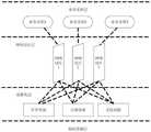
而且,所述步骤1的5G网络切片结构由基础架构层、NFV虚拟层、网络切片层与实际业务层组成;Moreover, the 5G network slicing structure in
而且,所述步骤2的资源分配控制器分为中心控制器和与其相连接的多个本地控制器;所述步骤2的中心控制器与本地控制器实时交互,用于获取整体网络全部信息,并根据信息给出相应的分配方案,之后将分配方案输出至本地控制器,进而实现各个局部承载网络业务的切片资源动态分配。Moreover, the resource allocation controller in
而且,所述步骤3的具体步骤包括:And, the specific steps of described
(1)根据网络映射请求分解为多个星型子虚拟网络请求:(1) According to the network mapping request, it is decomposed into multiple star sub-virtual network requests:
使用无向图Gp来代表5G切片网络,假设切片网络分配资源的总量为W(mjp)在网络节点上全部分布,用带宽B(mjp,mkp),表示底层节点mjp和mkp之间的物理链路,由此可以得到多业务网中分片的结构,其中虚拟层用无向图Gd表示,由虚拟层请求映射到底层物理资源网络的过程为:Use the undirected graph Gp to represent the 5G slice network, assuming that the total amount of resources allocated by the slice network is W(mjp ) distributed on all network nodes, and use the bandwidth B(mjp ,mkp ) to represent the underlying nodes The physical link between mjp and mkp can thus obtain the fragmented structure in the multi-service network, in which the virtual layer is represented by an undirected graph Gd , and the process of mapping the virtual layer request to the underlying physical resource network for:
Gd=(Nv,Ev)→Gp=(Np,Ep) (1)Gd =(Nv ,Ev )→Gp =(Np ,Ep ) (1)
式(1)中的Nv和Ev分别为虚拟层节点和链路的集合。Nv and Ev in formula (1) are the collection of virtual layer nodes and links respectively.
(2)以总带宽消耗最小为优化目标资进行源映射整合处理:(2) Perform source mapping integration processing with the minimum total bandwidth consumption as the optimization target resource:
资源映射整合期间,虚拟结点链路的剩余带宽资源按如下方式计算:During resource mapping integration, the remaining bandwidth resources of virtual node links are calculated as follows:

式(2)里,

RE(ME(ev))≥c(ev) (3)RE (ME (ev ))≥c(ev ) (3)
当虚拟资源请求存在多个有效映射时,以总带宽消耗最小为目标可以提高整个映射过程的资源利用率,从而获得电力多业务切片网络中各分块资源的映射结果,可按照映射特性对各分块资源进行分类。When there are multiple effective mappings for virtual resource requests, the resource utilization rate of the entire mapping process can be improved by aiming at the minimum total bandwidth consumption, so as to obtain the mapping results of each block resource in the power multi-service slice network, and each block can be mapped according to the mapping characteristics. Chunk resources for classification.
而且,所述步骤4的具体步骤包括:And, the specific steps of described step 4 include:
(1)分配时变随机信道:(1) Assign time-varying random channels:
分配过程中考虑随时间变化的随机信道,令gks(t)为时隙请求业务时用户k的信道增益,并满足以下条件:Consider the random channel that changes with time in the allocation process, let gks (t) be the channel gain of user k when the time slot requests service, and satisfy the following conditions:

公式(4)中,G为信道状态集合,P(gi)表示信道状态为gi的概率;令
(2)根据分配时变随机信道的结果,考虑信道的平均增益计算链路的剩余带宽是否满足切片资源量要求,对资源的分配信道进行选择:(2) According to the result of allocating time-varying random channels, consider the average gain of the channel to calculate whether the remaining bandwidth of the link meets the requirement of slice resources, and select the resource allocation channel:
计算链路的剩余带宽的公式为:The formula for calculating the remaining bandwidth of a link is:

在(5)中,BW(ls)是信道的总带宽,

而且,所述步骤5的具体方法为:And, the concrete method of described step 5 is:
以用户所属切片的权重ω为单位,按照自身所需服务的优先级分配网络资源:利用资源调度传输的间隔时间比较用户的优先级,并根据优先级的计算结果分配资源,使用(6)的计算方式表示用户优先级:Use the weight ω of the slice to which the user belongs, and allocate network resources according to the priority of the service required by the user: use the interval time of resource scheduling transmission to compare the priority of the user, and allocate resources according to the calculation result of the priority, using (6) The calculation method indicates the user priority:

其中,变量Su和SU为用户u和整个5G网络中所有用户的总需求。Among them, the variables Su and SU are the total demand of user u and all users in the entire 5G network.
而且,所述步骤6的具体方法为:And, the concrete method of described step 6 is:
使用效用函数V(Es)描述切片调度过程的优劣,要实现的资源调度目标是使V(Es)之和最大,即:Use the utility function V(Es ) to describe the advantages and disadvantages of the slice scheduling process. The resource scheduling goal to be achieved is to maximize the sum of V(Es ), namely:

式中,Es为单个切片的传输效率,E为资源调度效率总和。切片的权重ω用来对智能电网在某一时刻切片的能力进行描述。网片权重值的表达式为:In the formula, Es is the transmission efficiency of a single slice, and E is the sum of resource scheduling efficiencies. The slice weight ω is used to describe the slice capability of the smart grid at a certain moment. The expression of mesh weight value is:

其中,P0为切片计算出的带宽资源块数量,Pi表示i从0变化到i-1期间带宽资源块的平均值。加权系数为α,N0和Ni-1是整个资源调度过程和i-1调度时间间隔内的带宽资源块数量,λi为带宽资源块的利用率。Among them, P0 is the number of bandwidth resource blocks calculated by the slice, and Pi represents the average value of bandwidth resource blocks during the period wheni changes from 0 to i-1. The weighting coefficient is α, N0 and Ni-1 are the number of bandwidth resource blocks in the whole resource scheduling process and i-1 scheduling time interval, λi is the utilization rate of bandwidth resource blocks.
而且,所述步骤7的具体方法为:And, the concrete method of described step 7 is:
使用半静态方法分配用户所需的资源,设置所拥有的资源总数为L,根据切片类型、网络容量等因素,先进行固定的分配,满足各个用户所需的最低根本需求;经过第一轮分配后把剩下可用的资源记为L′,按照所求的优先级结果,由大到小,再次分配,直至全部分配结束。优先级高的用户可以进行信道优选,每一网络切片中,根据式(6)所求优先级,向每一网络切片的用户按照顺序分配资源,优先级更高得用户优可获得良好的信道,直至剩余资源为0。Use the semi-static method to allocate the resources required by users, set the total number of resources to be L, and perform fixed allocation first according to the slice type, network capacity and other factors to meet the minimum basic needs of each user; after the first round of allocation Finally, record the remaining available resources as L', according to the obtained priority results, from large to small, and re-allocate until all allocations are completed. Users with high priority can perform channel optimization. In each network slice, according to the priority obtained in formula (6), resources are allocated to users in each network slice in order. Users with higher priority can obtain good channels , until the remaining resource is 0.
而且,所述步骤8的具体步骤包括切片软隔离和切片硬隔离两部分:Moreover, the specific steps of
其中,切片软隔离的具体实现步骤包括:Among them, the specific implementation steps of slice soft isolation include:
(1)隔离等级的确定(1) Determination of isolation level
切片实例表示yi,切片的隔离等级Hiv由它的性能隔离等级Piv与安全隔离等级Siv共同决定,公式表示为Hiv=κ1Piv+κ2Siv,其中κ1+κ2=1,κ1、κ2的取值根据实际情况确定。两种隔离等级均可划分为5级,等级越高,相应的隔离需求越大;A slice instance represents yi , and the isolation level Hiv of the slice is determined by its performance isolation level Piv and the security isolation level Siv , and the formula is expressed as Hiv =κ1 Piv +κ2 Siv , where κ1 +κ2 =1, and the values of κ1 and κ2 are determined according to the actual situation. Both isolation levels can be divided into 5 levels, the higher the level, the greater the corresponding isolation requirements;
①性能隔离等级的确定:① Determination of performance isolation level:
将虚拟节点所需的资源与所剩资源的比值设置为性能隔离系数,设yi共有k个虚拟的节点,当第l个虚拟节点nyil被布放在服务器nsl上时,nyi,l的性能隔离系数

对于不同的虚拟节点,采用权重系数β对其进行调整,β1+β2+β3=1。


②安全隔离等级的确定:② Determination of safety isolation level:
针对yi中的k个虚拟节点,将它们部署在各个服务器上,设置在每个服务器上最多部署

根据
(2)变量的设定(2) Variable setting
现将第i个网络切片实例yi布放在物理到网络us上,yi共有k个虚拟节点,us共有n个物理节点,设置两个变量:Now place the i-th network slice instance yi on the physical network us , yi has k virtual nodes, us has n physical nodes, set two variables:
①αi,l,k:若yi的第l个虚拟节点nvi,l正常映射到us的第k个服务器
②βi,ef,ζ:若yi的虚拟链路,
(3)建立目标函数(3) Establish objective function
从成本角度出发,将最小化部署所需成本作为目标From a cost point of view, the goal is to minimize the cost required for deployment

上式中,部署虚拟节点nvi,l所耗费费用为Ωyi,l,部署虚拟链路

(4)建立约束条件(4) Establish constraints


式(12)表明当yi的第l个虚拟节点,nvi,l映射到us的第k个服务器

根据约束条件与目标函数,利用遗传算法求出最终的部署结果,基于已存在的网络机制,利用VLAN标签和切片标记来实现;不同的网络切片具有独有的标记;通过不同的VLAN进行隔离,进而实现逻辑信道划分和网络隔离,以共享网络带宽资源。According to the constraints and objective function, the genetic algorithm is used to obtain the final deployment result. Based on the existing network mechanism, VLAN tags and slice tags are used to realize; different network slices have unique tags; different VLANs are used for isolation, In turn, logical channel division and network isolation are realized to share network bandwidth resources.
其中,切片硬隔离的具体实现方法为:Among them, the specific implementation method of slice hard isolation is as follows:
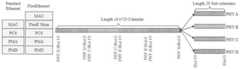
借助基于时隙的FlexE隔离技术,FlexE每100G物理PMD被分为20个Slot,它的Shim层有n×10个5G的时隙;通过它的Shim层的Slot配置可以支持多种不同业务的需求,实现电力多业务的网络切片之间的硬隔离。With the FlexE isolation technology based on time slots, each 100G physical PMD of FlexE is divided into 20 Slots, and its Shim layer has n×10 5G time slots; the Slot configuration of its Shim layer can support multiple different services. Requirements, to achieve hard isolation between network slices of electric power multi-services.
本发明的优点和有益效果:Advantages and beneficial effects of the present invention:
1、本发明提出一种基于SDN与NFV的面向5G多业务切片资源分配与隔离方法,通过5G网络切片,可以提供不同用例的网络即服务,支持运营商建立多个虚拟网络。通过网络切片可以动态、灵活地部署其应用和服务,满足多种业务需求。1. The present invention proposes a 5G multi-service slicing resource allocation and isolation method based on SDN and NFV. Through 5G network slicing, it can provide network-as-a-service for different use cases and support operators to establish multiple virtual networks. Through network slicing, applications and services can be deployed dynamically and flexibly to meet various business needs.
2、本发明分别从中心控制器和本地控制器两个方面,设计资源分配控制器,在硬件设备的控制下,收集资源并对其进行映射处理,由此降低分配拥塞的发生概率。选择资源分配信道并计算用户优先级,结合计算结果通过半动态调度的方式,实现5G网络切片资源优化分配。通过实验仿真得出结论:基于SDN与NFV的切片资源分配与传统模型相比,其发生拥塞情况与业务的概率更低,且能按照预先定义的优先级进行分配,更合理、更高效。2. The present invention designs a resource allocation controller from two aspects of the central controller and the local controller, collects resources and performs mapping processing on them under the control of hardware devices, thereby reducing the occurrence probability of allocation congestion. Select the resource allocation channel and calculate the user priority, combined with the calculation results through semi-dynamic scheduling, to realize the optimal allocation of 5G network slice resources. Through the experimental simulation, it is concluded that compared with the traditional model, the slice resource allocation based on SDN and NFV has lower probability of congestion and business, and can be allocated according to the predefined priority, which is more reasonable and efficient.
3、本发明针对性能隔离等级和安全隔离等级的加权和实现网络切片实例的隔离等级,将部署成本最小化作为目标函数,通过VLAN隔离实现逻辑信道的划分、网络共享网络带宽资源,保证用户在安全和性能两方面的隔离需求。对于具有极高时延和可靠性要求的uRLLC网络切片,采用基于时隙的FlexE隔离技术,实现物理隔离。3. The present invention aims at the weighting of performance isolation level and security isolation level and realizes the isolation level of network slicing instances, takes the minimization of deployment cost as the objective function, realizes logical channel division and network sharing of network bandwidth resources through VLAN isolation, and ensures that users Isolation requirements for both security and performance. For uRLLC network slices with extremely high latency and reliability requirements, the time slot-based FlexE isolation technology is used to achieve physical isolation.
附图说明Description of drawings
图1为本发明的5G网络切片技术架构图;Fig. 1 is a technical architecture diagram of 5G network slicing of the present invention;
图2为本发明的仿真实验网络场景图;Fig. 2 is the simulation experiment network scene figure of the present invention;
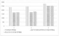
图3为本发明的网络切片资源分配量的统计对比结果图;FIG. 3 is a statistical comparison result diagram of network slice resource allocation according to the present invention;
图4为本发明的切片隔离等级GA-PSO算法流程图;Fig. 4 is the flow chart of slice isolation level GA-PSO algorithm of the present invention;
图5为本发明的部署成本仿真结果图;Fig. 5 is the deployment cost simulation result figure of the present invention;
图6为本发明的收益开销比仿真结果图;Fig. 6 is the benefit cost ratio simulation result figure of the present invention;
图7为本发明的基于时隙的FlexE隔离方案示意图。FIG. 7 is a schematic diagram of a time slot-based FlexE isolation solution according to the present invention.
具体实施方式detailed description
以下结合附图对本发明实施例作进一步详述:Embodiments of the present invention are described in further detail below in conjunction with the accompanying drawings:
一种基于SDN与NFV的面向5G多业务切片资源分配与隔离方法,包括以下步骤:A 5G multi-service slice resource allocation and isolation method based on SDN and NFV, comprising the following steps:
步骤1、搭建5G网络切片结构
所述5G网络切片结构由基础架构层、NFV虚拟层、网络切片层与实际业务层组成;The 5G network slicing structure is composed of an infrastructure layer, an NFV virtual layer, a network slicing layer and an actual service layer;
在本实施例中,首先需要根据“5G白皮书”搭建网络切片结构,一般由基础架构层、NFV虚拟层、网络切片层与实际业务层组成。In this embodiment, it is first necessary to build a network slicing structure according to the "5G White Paper", which generally consists of an infrastructure layer, an NFV virtual layer, a network slicing layer, and an actual service layer.
基础架构层:与NFV虚拟层连接,提供资源,包括进行NFV过程所需的物理资源,计算、存储资源、网元部件,以及驱动、传感设备等。Infrastructure layer: Connect with the NFV virtualization layer to provide resources, including physical resources required for NFV process, computing, storage resources, network element components, and drive and sensor devices.
NFV虚拟层:依靠SDN和NFV实现,SDN指软件定义网络、NFV是网络虚拟化层,基础结构层与其他平面可以根据SDN进行分离,NFV可以从硬件资源中分离出需要的网络功能,NFV还能够协调网片段的生命周期,管控虚拟网络功能。NFV virtual layer: rely on SDN and NFV to achieve, SDN refers to software-defined network, NFV is the network virtualization layer, the infrastructure layer and other planes can be separated according to SDN, NFV can separate the required network functions from hardware resources, NFV also It can coordinate the life cycle of network segments and manage and control virtual network functions.
网络切片层:分片由虚拟网络功能VNFs组成,该功能在虚拟结构上实现,再选择网络功能单元实体实现相应业务需要。Network slicing layer: The slicing is composed of virtual network function VNFs, which are implemented on the virtual structure, and then the network function unit entity is selected to realize the corresponding business needs.
实际业务层:业务被分配相应的切片后,形成对应的网络连接,实现消息传输,从而实现广泛的应用。Actual business layer: After the business is allocated to the corresponding slice, a corresponding network connection is formed to realize message transmission, thereby realizing a wide range of applications.
步骤2、基于步骤1搭建5G网络切片结构,在NFV虚拟层设计资源分配控制器;
所述步骤2的资源分配控制器分为中心控制器和与其相连接的多个本地控制器;The resource allocation controller in
其中,所述中心控制器与本地控制器实时交互,用于获取整体网络全部信息,并根据信息给出相应的分配方案,之后将分配方案输出至本地控制器,进而实现各个局部承载网络业务的切片资源动态分配。Wherein, the central controller interacts with the local controller in real time to obtain all information of the overall network, and provides a corresponding distribution plan according to the information, and then outputs the distribution plan to the local controller, thereby realizing the distribution of services in each local bearer network. Slice resources are allocated dynamically.
在本实施例中,所述本地控制器用于接收中心控制器发出的指令,根据指令进行相应分配,对网络切片中各个虚拟网元的资源进行编排和管理,按照用户端点需要实现端到端网络切片资源的分配;并收集基础设施和虚拟网元的资源使用情况,并将其上传到中心控制器。In this embodiment, the local controller is used to receive the instructions issued by the central controller, and allocate correspondingly according to the instructions, arrange and manage the resources of each virtual network element in the network slice, and realize the end-to-end network according to the needs of the user endpoints. Allocation of slice resources; and collect resource usage of infrastructure and virtual network elements, and upload it to the central controller.
基于此,中心控制器能够根据各类需求进行资源的分配,在判断切换前后的业务是否符合业务需求后,中心控制器会按照用户需求、各个局部分区的网络状态、资源状况等,针对综合考虑对各区域部署的资源分配算法,制定相应的资源分配策略,将分配方式发送到局部的本地控制器。本地控制器收集基础设施和虚拟网元的资源使用情况,并将其上传到中心控制器,它还能够根据所收到的分配策略,动态地为虚拟网元分配资源,满足业务需求,从而实现网络虚拟化计算、存储和资源的管控操作。Based on this, the central controller can allocate resources according to various needs. After judging whether the business before and after the switch meets the business needs, the central controller will comprehensively consider the For the resource allocation algorithms deployed in each region, formulate corresponding resource allocation strategies, and send the allocation methods to local local controllers. The local controller collects the resource usage of infrastructure and virtual network elements, and uploads them to the central controller. It can also dynamically allocate resources for virtual network elements according to the received allocation strategy to meet business needs, thereby realizing Management and control operations of network virtualization computing, storage and resources.
在本实施例中,设计资源分配控制器,它分为中心与本地控制。中心控制器可通过相应的程序接口与本地控制器实时交互,它能够获取整体网络全部信息,根据信息给出相应的分配方案,之后通过接口传送给本地控制器,进而实现各个局部承载网络业务的切片资源动态分配。In this embodiment, a resource allocation controller is designed, which is divided into central and local control. The central controller can interact with the local controller in real time through the corresponding program interface. It can obtain all the information of the overall network, give the corresponding allocation plan according to the information, and then send it to the local controller through the interface, and then realize the distribution of network services in various parts. Slice resources are allocated dynamically.
本地控制主要是接受控制中心发来的指令,根据指令进行相应分配,对网络切片中各个虚拟网元的资源进行编排和管理,实现资源的弹性扩展,按照用户端点需要实现端到端网络切片资源的分配。基于此,中心控制器能够根据各类需求进行资源的分配,在判断切换前后的业务是否符合业务需求后,中心管控处会按照用户需求、各个局部分区的网络状态、资源状况等,针对综合考虑对各区域部署的资源分配算法,制定相应的资源分配策略,将分配方式发送到本地控制器。本地控制器收集基础设施和虚拟网元的资源使用情况,并将其上传到中心端,它还能够根据所收到的分配策略,动态地为虚拟网元分配资源,满足业务需求,从而实现网络虚拟化计算、存储和资源的管控操作。The local control is mainly to accept the instructions sent by the control center, allocate correspondingly according to the instructions, arrange and manage the resources of each virtual network element in the network slice, realize the elastic expansion of resources, and realize end-to-end network slice resources according to the needs of user endpoints allocation. Based on this, the central controller can allocate resources according to various needs. After judging whether the business before and after the switch meets the business needs, the central management and control office will comprehensively consider the For the resource allocation algorithms deployed in each area, formulate corresponding resource allocation strategies, and send the allocation methods to the local controller. The local controller collects the resource usage of infrastructure and virtual network elements, and uploads them to the central end. It can also dynamically allocate resources for virtual network elements according to the received allocation strategy to meet business needs, thereby realizing network Manage and control operations of virtualized computing, storage, and resources.
步骤3、在NFV层收集切片资源,并以总带宽消耗最小为优化目标对其进行资源映射整合处理,提高整个映射过程的资源利用率;
所述步骤3的具体步骤包括:The concrete steps of described
(1)根据网络映射请求分解为多个星型子虚拟网络请求:(1) According to the network mapping request, it is decomposed into multiple star sub-virtual network requests:
使用无向图Gp来代表5G切片网络,假设切片网络分配资源的总量为W(mjp)在网络节点上全部分布,用带宽B(mjp,mkp),表示底层节点mjp和mkp之间的物理链路,由此可以得到多业务网中分片的结构,其中虚拟层用无向图Gd表示,由虚拟层请求映射到底层物理资源网络的过程为:Use the undirected graph Gp to represent the 5G slice network, assuming that the total amount of resources allocated by the slice network is W(mjp ) distributed on all network nodes, and use the bandwidth B(mjp ,mkp ) to represent the underlying nodes The physical link between mjp and mkp can thus obtain the fragmented structure in the multi-service network, in which the virtual layer is represented by an undirected graph Gd , and the process of mapping the virtual layer request to the underlying physical resource network for:
Gd=(Nv,Ev)→Gp=(Np,Ep) (1)Gd =(Nv ,Ev )→Gp =(Np ,Ep ) (1)
式(1)中的Nv和Ev分别为虚拟层节点和链路的集合。Nv and Ev in formula (1) are the collection of virtual layer nodes and links respectively.
在本实施例中,采用星型拓扑结构,在虚拟网络中需要考虑虚拟网络的拓扑特性,防止因为底层链路的利用不合理,而带来的网络信道拥塞现。In this embodiment, a star topology is adopted, and topology characteristics of the virtual network need to be considered in the virtual network to prevent network channel congestion caused by unreasonable utilization of underlying links.
(2)以总带宽消耗最小为优化目标资进行源映射整合处理:(2) Perform source mapping integration processing with the minimum total bandwidth consumption as the optimization target resource:
资源映射整合期间,虚拟结点链路的剩余带宽资源按如下方式计算:During resource mapping integration, the remaining bandwidth resources of virtual node links are calculated as follows:

式(2)里,

RE(ME(ev))≥c(ev) (3)RE (ME (ev ))≥c(ev ) (3)
当虚拟资源请求存在多个有效映射时,以总带宽消耗最小为目标可以提高整个映射过程的资源利用率。从而获得电力多业务切片网络中各分块资源的映射结果,可按照映射特性对各分块资源进行分类。When there are multiple valid mappings for a virtual resource request, aiming to minimize the total bandwidth consumption can improve the resource utilization of the entire mapping process. In this way, the mapping result of each block resource in the power multi-service slicing network can be obtained, and each block resource can be classified according to the mapping characteristics.
步骤4、进行资源映射整合处理后,选择资源分配信道;Step 4. After performing resource mapping and integration processing, select a resource allocation channel;
所述步骤4的具体步骤包括:The concrete steps of described step 4 include:
(1)分配时变随机信道:(1) Assign time-varying random channels:
分配过程中考虑随时间变化的随机信道,令gks(t)为时隙请求业务时用户k的信道增益,并满足以下条件:Consider the random channel that changes with time in the allocation process, let gks (t) be the channel gain of user k when the time slot requests service, and satisfy the following conditions:

公式(4)中,G为信道状态集合,P(gi)表示信道状态为gi的概率。令
(2)根据分配时变随机信道的结果,考虑信道的平均增益计算链路的剩余带宽是否满足切片资源量要求,对资源的分配信道进行选择:(2) According to the result of allocating time-varying random channels, consider the average gain of the channel to calculate whether the remaining bandwidth of the link meets the requirement of slice resources, and select the resource allocation channel:
计算链路的剩余带宽的公式为:The formula for calculating the remaining bandwidth of a link is:

在(5)中,BW(ls)是信道的总带宽,

步骤5、按照自身所需服务计算用户优先级;Step 5. Calculate the user priority according to the required service;
所述步骤5的具体方法为:The concrete method of described step 5 is:
以用户所属切片的权重ω为单位,按照自身所需服务的优先级分配网络资源:利用资源调度传输的间隔时间比较用户的优先级,并根据优先级的计算结果分配资源。使用(6)的计算方式表示用户优先级Use the weight ω of the slice to which the user belongs, and allocate network resources according to the priority of the services required by the user: use the interval time of resource scheduling transmission to compare the priority of the user, and allocate resources according to the calculation result of the priority. Use the calculation method of (6) to indicate user priority

其中,变量Su和SU为用户u和整个5G网络中所有用户的总需求。Among them, the variables Su and SU are the total demand of user u and all users in the entire 5G network.
步骤6、以映射处理完成的资源为对象,在分片资源分配通道中进行资源调度,使效用函数最大Step 6. Taking the resource that has been mapped as the object, perform resource scheduling in the fragmented resource allocation channel to maximize the utility function
所述步骤6的具体方法为:The concrete method of described step 6 is:
使用效用函数V(Es)描述切片调度过程的优劣,要实现的资源调度目标是使V(Es)之和最大,即:Use the utility function V(Es ) to describe the advantages and disadvantages of the slice scheduling process. The resource scheduling goal to be achieved is to maximize the sum of V(Es ), namely:

式中,Es为单个切片的传输效率,E为资源调度效率总和。切片的权重ω用来对智能电网在某一时刻切片的能力进行描述。网片权重值的表达式为:In the formula, Es is the transmission efficiency of a single slice, and E is the sum of resource scheduling efficiencies. The slice weight ω is used to describe the slice capability of the smart grid at a certain moment. The expression of mesh weight value is:

其中,P0为切片计算出的带宽资源块数量,Pi表示i从0变化到i-1期间带宽资源块的平均值。加权系数为α,N0和Ni-1是整个资源调度过程和i-1调度时间间隔内的带宽资源块数量,λi为带宽资源块的利用率。Among them, P0 is the number of bandwidth resource blocks calculated by the slice, and Pi represents the average value of bandwidth resource blocks during the period wheni changes from 0 to i-1. The weighting coefficient is α, N0 and Ni-1 are the number of bandwidth resource blocks in the whole resource scheduling process and i-1 scheduling time interval, λi is the utilization rate of bandwidth resource blocks.
步骤7、根据以上步骤的处理结果进行资源优化分配Step 7. Optimize resource allocation according to the processing results of the above steps
所述步骤7的具体方法为:The concrete method of described step 7 is:
使用半静态方法分配用户所需的资源,设置我们所拥有的资源总数为L,根据切片类型、网络容量等因素,先进行固定的分配,满足各个用户所需的最低根本需求。经过第一轮分配后把剩下可用的资源记为L′,按照所求的优先级结果,由大到小,再次分配,直至全部分配结束。优先级高的用户可以进行信道优选,每一网络切片中,根据式(6)所求优先级,向每一网络切片的用户按照顺序分配资源,优先级更高得用户优可获得良好的信道,直至剩余资源为0。Use a semi-static method to allocate the resources required by users, set the total number of resources we have to L, and perform fixed allocation first according to factors such as slice type and network capacity to meet the minimum fundamental needs of each user. After the first round of allocation, the remaining available resources are recorded as L', according to the obtained priority results, from large to small, and re-allocated until all allocations are completed. Users with high priority can perform channel optimization. In each network slice, according to the priority obtained by formula (6), resources are allocated to users in each network slice in order. Users with higher priority can obtain good channels , until the remaining resource is 0.
步骤8、完成资源分配后,根据业务需求进行切片隔离
针对网络中各业务对安全的需求不同,为了避免5G网络各切片之间可能发生的资源争夺而影响业务的正常进行,进而带来的安全性等问题。我们要兼顾网络切片的性能与安全需求对切片资源进行分配,之后再进行隔离。如今在5G切片应用上,隔离方法以软切片为主,通过业务的性能与安全需求提供不同业务等级,以逻辑隔离的方式按需提供端到端的差异化服务,这种方式较易实现。而切片若要实现网络专用等物理隔离即硬隔离,为不同的网络切片在网络中分配完全独享的网络资源,但由于其成本代价较高,一般是针对对安全需求极高的业务,需要结合用户实际业务场景,根据成本按需提供。In view of the different security requirements of various services in the network, in order to avoid the possible resource contention among the 5G network slices, which will affect the normal operation of the business, and thus bring security and other issues. We need to allocate slice resources taking into account the performance and security requirements of network slices, and then isolate them. Today, in 5G slicing applications, soft slicing is the main isolation method. Different service levels are provided based on service performance and security requirements, and end-to-end differentiated services are provided on demand in a logically isolated manner. This method is easier to implement. However, if slicing needs to achieve physical isolation such as dedicated network, that is, hard isolation, completely exclusive network resources are allocated in the network for different network slices. Combined with the user's actual business scenario, it is provided on demand according to the cost.
所述步骤8的具体步骤包括切片软隔离和切片硬隔离两部分:The specific steps of said
其中,切片软隔离的具体实现步骤包括:Among them, the specific implementation steps of slice soft isolation include:
(1)隔离等级的确定(1) Determination of isolation level
切片实例表示yi,切片的隔离等级Hiv由它的性能隔离等级Piv与安全隔离等级Siv共同决定,公式表示为Hiv=κ1Piv+κ2Siv,其中κ1+κ2=1,κ1、κ2的取值根据实际情况确定。两种隔离等级均可划分为5级,等级越高,相应的隔离需求越大。A slice instance represents yi , and the isolation level Hiv of the slice is determined by its performance isolation level Piv and the security isolation level Siv , and the formula is expressed as Hiv =κ1 Piv +κ2 Siv , where κ1 +κ2 =1, and the values of κ1 and κ2 are determined according to the actual situation. Both isolation levels can be divided into 5 levels, the higher the level, the greater the corresponding isolation requirements.
性能隔离等级的确定:Determination of performance isolation level:
将虚拟节点所需的资源与所剩资源的比值设置为性能隔离系数。设yi共有k个虚拟的节点,当第l个虚拟节点nyil被布放在服务器nsl上时,nyi,l的性能隔离系数

对于不同的虚拟节点,采用权重系数β对其进行调整,β1+β2+β3=1。


安全隔离等级的确定:Determination of security isolation level:
针对某一网络切片实例(NSI),如果与它共享资源的切片数量越多,它就越可能遇到恶意攻击。针对yi中的k个虚拟节点,将它们部署在各个服务器上,设置在每个服务器上最多部署

根据
(2)变量的设定(2) Variable setting
现将第i个网络切片实例yi布放在物理到网络us上,yi共有k个虚拟节点,us共有n个物理节点,设置两个变量。①αi,l,k:若yi的第l个虚拟节点nvi,l正常映射到us的第k个服务器
(3)建立目标函数(3) Establish objective function
从成本角度出发,将最小化部署所需成本作为我们的目标From a cost point of view, it is our goal to minimize the cost of deployment

上式中,部署虚拟节点


(4)建立约束条件(4) Establish constraints


式(12)表明当yi的第l个虚拟节点,nvi,l映射到us的第k个服务器

根据约束条件与目标函数,利用遗传算法求出最终的部署结果,基于已存在的网络机制,利用VLAN标签和切片标记来实现。不同的网络切片具有独有的标记。通过不同的VLAN进行隔离,进而实现逻辑信道划分和网络隔离,以共享网络带宽资源。According to the constraints and objective function, the genetic algorithm is used to obtain the final deployment result, and based on the existing network mechanism, VLAN tags and slice tags are used to realize it. Different network slices have unique tags. Isolate through different VLANs, and then realize logical channel division and network isolation to share network bandwidth resources.
其中,切片硬隔离的具体实现方法为:Among them, the specific implementation method of slice hard isolation is as follows:
借助基于时隙的FlexE隔离技术,FlexE每100G物理PMD被分为20个Slot,它的Shim层有n×10个5G的时隙。通过它的Shim层的Slot配置可以支持多种不同业务的需求,实现电力多业务的网络切片之间的硬隔离。With the FlexE isolation technology based on time slots, each 100G physical PMD of FlexE is divided into 20 slots, and its Shim layer has n×10 5G time slots. Through the Slot configuration of its Shim layer, it can support the requirements of multiple different services, and realize hard isolation between network slices of electric power multi-services.
在本实施例中,图1所示为根据“5G网络架构设计”白皮书,搭建的5G网络切片技术架构。In this embodiment, FIG. 1 shows the technical architecture of 5G network slicing built according to the white paper "5G Network Architecture Design".
为验证所提方法的有效性,假设运营商同时建设若干个网络片,资源总数16个,每个网络片分配的资源数为5个,剩下的资源需要根据用户优先级进行分配,每个网络片有6个在线用户。In order to verify the effectiveness of the proposed method, it is assumed that the operator builds several network slices at the same time, the total number of resources is 16, and the number of resources allocated to each network slice is 5, and the remaining resources need to be allocated according to user priorities. The web slice has 6 online users.
图2表明了我们构建的场景。Figure 2 shows the scene we constructed.
表1网络切片仿真中我们所设置参数的值。Table 1 The values of the parameters we set in the network slicing simulation.
表1仿真参数设置表Table 1 Simulation parameter setting table

根据风险评价方法的应用得出三种资源分配模型分配拥塞中断概率的测试结果,取7次实验的,根据实验平均值得出结果,如表2所示,它们的平均拥塞中断概率分布为0.24、0.17和0.03,可以看出设计模型的拥塞概率明显低于两个对比模型,效率与安全性更高。According to the application of the risk assessment method, the test results of the three resource allocation models for the distribution of congestion interruption probability are obtained. Seven experiments are taken, and the results are obtained according to the average value of the experiment. As shown in Table 2, their average congestion interruption probability distribution is 0.24, 0.17 and 0.03, it can be seen that the congestion probability of the design model is significantly lower than the two comparison models, and the efficiency and security are higher.
表2分配拥塞中断概率量化对比结果Table 2 Quantitative comparison results of allocation congestion interruption probability

图3所示为三种分配方法网络切片资源分配量的统计对比结果,综合三次实验结果,构建的基于智能电网的5G网络切片资源优化分配模型的资源分配量更多,即吞吐量更大。Figure 3 shows the statistical comparison results of network slice resource allocation of the three allocation methods. Based on the results of the three experiments, the smart grid-based 5G network slice resource optimization allocation model constructed has more resource allocation, that is, greater throughput.
图4所示为在软隔离约束条件的求解中所采用的基于遗传算法优化的离散粒子群算法的流程框图,用该方法求解最终的部署结果。Figure 4 is a flow chart of the discrete particle swarm optimization algorithm based on genetic algorithm used in the solution of the soft isolation constraints, using this method to solve the final deployment results.
图5所示为仿真结果所显示,不同方法的部署成本总和的变化情况。可以看出,随着NSI请求数量增多,部署成本总和均呈现增长的趋势,但本文方法的部署成本总和增长速率低于基于安全等级的虚拟机动态迁移方法和最小化共存度的方法,最小化共存度的方法部署成本增长速率最高。Figure 5 shows the variation of the sum of deployment costs of different methods as shown by the simulation results. It can be seen that as the number of NSI requests increases, the total deployment cost shows an increasing trend, but the growth rate of the total deployment cost of the method in this paper is lower than that of the virtual machine dynamic migration method based on security level and the method of minimizing the coexistence degree. The coexistence method has the highest growth rate of deployment cost.
图6所示为仿真结果,表现了不同方法下收益开销的对比情况。我们可以看出,随着网络切片实例的需求数量增加,收益开销三种方法都增长,但我们提出的方法的收益开销最高,效果最好。Figure 6 shows the simulation results, showing the comparison of revenue and expenditure under different methods. We can see that as the demand for network slicing instances increases, the revenue and cost of the three methods all increase, but the method we propose has the highest revenue and cost and the best effect.
图7所示为在硬隔离方案采用的基于灵活以太网(FlexE)技术,将物理以太网端口划分为多个硬隔离管道使得网络既具备以太网统计复用的优点,并且独占时隙、隔离性好。Figure 7 shows the flexible Ethernet (FlexE) technology adopted in the hard isolation solution. The physical Ethernet port is divided into multiple hard isolation pipes so that the network not only has the advantages of Ethernet statistical multiplexing, but also monopolizes time slots and isolates Good sex.
需要强调的是,本发明所述实施例是说明性的,而不是限定性的,因此本发明包括并不限于具体实施方式中所述实施例,凡是由本领域技术人员根据本发明的技术方案得出的其他实施方式,同样属于本发明保护的范围。It should be emphasized that the embodiments of the present invention are illustrative rather than restrictive, so the present invention includes and is not limited to the embodiments described in the specific implementation, and those who are obtained by those skilled in the art according to the technical solutions of the present invention Other implementation modes mentioned above also belong to the protection scope of the present invention.
Claims (9)
Translated fromChinese


Priority Applications (1)
| Application Number | Priority Date | Filing Date | Title |
|---|---|---|---|
| CN202210874625.5ACN115460088A (en) | 2022-07-25 | 2022-07-25 | 5G power multi-service slice resource allocation and isolation method |
Applications Claiming Priority (1)
| Application Number | Priority Date | Filing Date | Title |
|---|---|---|---|
| CN202210874625.5ACN115460088A (en) | 2022-07-25 | 2022-07-25 | 5G power multi-service slice resource allocation and isolation method |
Publications (1)
| Publication Number | Publication Date |
|---|---|
| CN115460088Atrue CN115460088A (en) | 2022-12-09 |
Family
ID=84296228
Family Applications (1)
| Application Number | Title | Priority Date | Filing Date |
|---|---|---|---|
| CN202210874625.5APendingCN115460088A (en) | 2022-07-25 | 2022-07-25 | 5G power multi-service slice resource allocation and isolation method |
Country Status (1)
| Country | Link |
|---|---|
| CN (1) | CN115460088A (en) |
Cited By (7)
| Publication number | Priority date | Publication date | Assignee | Title |
|---|---|---|---|---|
| CN116208959A (en)* | 2023-05-04 | 2023-06-02 | 中建五洲工程装备有限公司 | Digital intelligent manufacturing management method and system based on 5G private network |
| CN116366446A (en)* | 2023-02-10 | 2023-06-30 | 国网山东省电力公司经济技术研究院 | A method and system for isolation and bearing of a power distribution communication network |
| CN116436782A (en)* | 2023-06-09 | 2023-07-14 | 中国电信股份有限公司四川分公司 | Deterministic network transmission method for embodying business willingness |
| CN117098239A (en)* | 2023-10-17 | 2023-11-21 | 国网信息通信产业集团有限公司 | Power scene-oriented wireless resource double-layer isolation distribution method and system |
| CN117998594A (en)* | 2024-01-02 | 2024-05-07 | 国网河北省电力有限公司信息通信分公司 | 5G power multi-service slice resource allocation method, device and system |
| CN118331678A (en)* | 2024-02-08 | 2024-07-12 | 山东华科信息技术有限公司 | Novel multi-time-scale fine-granularity parallel simulation method and system for power distribution network |
| CN119835702A (en)* | 2024-12-31 | 2025-04-15 | 国网四川省电力公司电力科学研究院 | Method and system for optimizing resource allocation in RAN slices |
Citations (3)
| Publication number | Priority date | Publication date | Assignee | Title |
|---|---|---|---|---|
| CN111131258A (en)* | 2019-12-26 | 2020-05-08 | 中移(成都)信息通信科技有限公司 | Safe private network architecture system based on 5G network slice |
| CN113055887A (en)* | 2021-05-18 | 2021-06-29 | 全球能源互联网研究院有限公司 | Network channel safety protection system for electric power 5G application |
| CN114268548A (en)* | 2021-12-24 | 2022-04-01 | 国网河南省电力公司信息通信公司 | Network slice resource arranging and mapping method based on 5G |
- 2022
- 2022-07-25CNCN202210874625.5Apatent/CN115460088A/enactivePending
Patent Citations (3)
| Publication number | Priority date | Publication date | Assignee | Title |
|---|---|---|---|---|
| CN111131258A (en)* | 2019-12-26 | 2020-05-08 | 中移(成都)信息通信科技有限公司 | Safe private network architecture system based on 5G network slice |
| CN113055887A (en)* | 2021-05-18 | 2021-06-29 | 全球能源互联网研究院有限公司 | Network channel safety protection system for electric power 5G application |
| CN114268548A (en)* | 2021-12-24 | 2022-04-01 | 国网河南省电力公司信息通信公司 | Network slice resource arranging and mapping method based on 5G |
Non-Patent Citations (4)
| Title |
|---|
| 李锦煊等: "基于智能电网的5G网络切片资源优化分配模型构建及仿真", 自动化与仪器仪表, no. 11, pages 36 - 39* |
| 段宏等: "FlexE技术及其在5G承载网中的应用探析", 邮电设计技术, no. 3, pages 80 - 85* |
| 潘启润等: "基于隔离等级的网络切片部署方法", 网络与信息安全学报, vol. 6, no. 2, pages 96 - 105* |
| 陶志强等: "泛在电力物联网前沿安全技术", 中国电信业, no. 7, 31 July 2020 (2020-07-31), pages 71 - 73* |
Cited By (11)
| Publication number | Priority date | Publication date | Assignee | Title |
|---|---|---|---|---|
| CN116366446A (en)* | 2023-02-10 | 2023-06-30 | 国网山东省电力公司经济技术研究院 | A method and system for isolation and bearing of a power distribution communication network |
| CN116208959A (en)* | 2023-05-04 | 2023-06-02 | 中建五洲工程装备有限公司 | Digital intelligent manufacturing management method and system based on 5G private network |
| CN116436782A (en)* | 2023-06-09 | 2023-07-14 | 中国电信股份有限公司四川分公司 | Deterministic network transmission method for embodying business willingness |
| CN116436782B (en)* | 2023-06-09 | 2023-09-29 | 中国电信股份有限公司四川分公司 | Deterministic network transmission method for embodying business willingness |
| CN117098239A (en)* | 2023-10-17 | 2023-11-21 | 国网信息通信产业集团有限公司 | Power scene-oriented wireless resource double-layer isolation distribution method and system |
| CN117098239B (en)* | 2023-10-17 | 2024-03-19 | 国网信息通信产业集团有限公司 | Power scene-oriented wireless resource double-layer isolation distribution method and system |
| CN117998594A (en)* | 2024-01-02 | 2024-05-07 | 国网河北省电力有限公司信息通信分公司 | 5G power multi-service slice resource allocation method, device and system |
| CN117998594B (en)* | 2024-01-02 | 2025-01-28 | 国网河北省电力有限公司信息通信分公司 | 5G power multi-service slice resource allocation method, device and system |
| CN118331678A (en)* | 2024-02-08 | 2024-07-12 | 山东华科信息技术有限公司 | Novel multi-time-scale fine-granularity parallel simulation method and system for power distribution network |
| CN118331678B (en)* | 2024-02-08 | 2025-02-11 | 山东华科信息技术有限公司 | A novel multi-time scale fine-grained parallel simulation method and system for distribution network |
| CN119835702A (en)* | 2024-12-31 | 2025-04-15 | 国网四川省电力公司电力科学研究院 | Method and system for optimizing resource allocation in RAN slices |
Similar Documents
| Publication | Publication Date | Title |
|---|---|---|
| CN115460088A (en) | 5G power multi-service slice resource allocation and isolation method | |
| CN109684075B (en) | Method for unloading computing tasks based on edge computing and cloud computing cooperation | |
| CN111246586B (en) | A method and system for allocating smart grid resources based on genetic algorithm | |
| CN106411770B (en) | A kind of data center network energy-saving routing algorithm based on SDN framework | |
| CN109062668B (en) | A multi-priority virtual network function migration method based on 5G access network | |
| CN103294521B (en) | A kind of method reducing data center's traffic load and energy consumption | |
| CN104468212B (en) | A kind of cloud computation data center network intelligence linkage collocation method and system | |
| CN101110701B (en) | Energy-saving method, system and equipment for distributed system | |
| CN102981890B (en) | A kind of calculation task in Visualized data centre and virtual machine deployment method | |
| CN108012307B (en) | Wireless heterogeneous network selection method, apparatus, device and readable storage medium | |
| CN108111931A (en) | A virtual resource slice management method and device for power optical fiber access network | |
| CN111953510A (en) | A smart grid slice wireless resource allocation method and system based on reinforcement learning | |
| CN110365526A (en) | A VNF deployment method and system for energy saving and QoS guarantee | |
| CN103645795A (en) | Cloud computing data center energy saving method based on ANN (artificial neural network) | |
| CN111526057A (en) | A Service Type-Based Network Slicing Reliability Mapping Algorithm | |
| CN115103412B (en) | A 5G smart grid slice allocation method based on deep reinforcement learning | |
| CN106060851A (en) | Secure resource optimization method under congestion control in heterogeneous cloud wireless access network | |
| Yi et al. | Energy‐aware disaster backup among cloud datacenters using multiobjective reinforcement learning in software defined network | |
| Xing et al. | Task classification unloading algorithm for mobile edge computing in smart grid | |
| CN102104542A (en) | Method for realizing service group router under forwarding and controlling separated network architecture | |
| CN115048260A (en) | Cloud computing-based nuclear power plant PaaS platform resource quota monitoring method and system | |
| CN116302578A (en) | A QoS-constrained streaming application delay assurance method and system | |
| WO2024244415A1 (en) | Mmtc network slice mapping method and system based on group authentication | |
| CN117956557A (en) | 5G-R base station energy-saving control and system based on service load prediction | |
| Yu et al. | An energy-aware algorithm for optimizing resource allocation in software defined network |
Legal Events
| Date | Code | Title | Description |
|---|---|---|---|
| PB01 | Publication | ||
| PB01 | Publication | ||
| SE01 | Entry into force of request for substantive examination | ||
| SE01 | Entry into force of request for substantive examination | ||
| RJ01 | Rejection of invention patent application after publication | Application publication date:20221209 | |
| RJ01 | Rejection of invention patent application after publication |