CN115451378A - Cover - Google Patents
CoverDownload PDFInfo
- Publication number
- CN115451378A CN115451378ACN202210644081.3ACN202210644081ACN115451378ACN 115451378 ACN115451378 ACN 115451378ACN 202210644081 ACN202210644081 ACN 202210644081ACN 115451378 ACN115451378 ACN 115451378A
- Authority
- CN
- China
- Prior art keywords
- resin
- gate
- cover
- resin portion
- resin part
- Prior art date
- Legal status (The legal status is an assumption and is not a legal conclusion. Google has not performed a legal analysis and makes no representation as to the accuracy of the status listed.)
- Pending
Links
- 239000011347resinSubstances0.000claimsabstractdescription234
- 229920005989resinPolymers0.000claimsabstractdescription234
- 239000003086colorantSubstances0.000claimsdescription4
- 239000002184metalSubstances0.000description15
- 239000010410layerSubstances0.000description6
- 239000003566sealing materialSubstances0.000description4
- 239000000758substrateSubstances0.000description3
- 238000001816coolingMethods0.000description2
- 238000010586diagramMethods0.000description2
- 238000000034methodMethods0.000description2
- 230000002093peripheral effectEffects0.000description2
- 239000004925Acrylic resinSubstances0.000description1
- 229920000178Acrylic resinPolymers0.000description1
- 230000001154acute effectEffects0.000description1
- 239000012790adhesive layerSubstances0.000description1
- 230000006866deteriorationEffects0.000description1
- 230000000694effectsEffects0.000description1
- 238000004519manufacturing processMethods0.000description1
- 239000003550markerSubstances0.000description1
- 239000000463materialSubstances0.000description1
- 238000000465mouldingMethods0.000description1
- 238000012856packingMethods0.000description1
- 238000007789sealingMethods0.000description1
- 238000002834transmittanceMethods0.000description1
Images


Classifications
- F—MECHANICAL ENGINEERING; LIGHTING; HEATING; WEAPONS; BLASTING
- F21—LIGHTING
- F21V—FUNCTIONAL FEATURES OR DETAILS OF LIGHTING DEVICES OR SYSTEMS THEREOF; STRUCTURAL COMBINATIONS OF LIGHTING DEVICES WITH OTHER ARTICLES, NOT OTHERWISE PROVIDED FOR
- F21V3/00—Globes; Bowls; Cover glasses
- F—MECHANICAL ENGINEERING; LIGHTING; HEATING; WEAPONS; BLASTING
- F21—LIGHTING
- F21S—NON-PORTABLE LIGHTING DEVICES; SYSTEMS THEREOF; VEHICLE LIGHTING DEVICES SPECIALLY ADAPTED FOR VEHICLE EXTERIORS
- F21S43/00—Signalling devices specially adapted for vehicle exteriors, e.g. brake lamps, direction indicator lights or reversing lights
- F21S43/20—Signalling devices specially adapted for vehicle exteriors, e.g. brake lamps, direction indicator lights or reversing lights characterised by refractors, transparent cover plates, light guides or filters
- F21S43/26—Refractors, transparent cover plates, light guides or filters not provided in groups F21S43/235 - F21S43/255
- B—PERFORMING OPERATIONS; TRANSPORTING
- B29—WORKING OF PLASTICS; WORKING OF SUBSTANCES IN A PLASTIC STATE IN GENERAL
- B29C—SHAPING OR JOINING OF PLASTICS; SHAPING OF MATERIAL IN A PLASTIC STATE, NOT OTHERWISE PROVIDED FOR; AFTER-TREATMENT OF THE SHAPED PRODUCTS, e.g. REPAIRING
- B29C45/00—Injection moulding, i.e. forcing the required volume of moulding material through a nozzle into a closed mould; Apparatus therefor
- B29C45/16—Making multilayered or multicoloured articles
- B29C45/1615—The materials being injected at different moulding stations
- B—PERFORMING OPERATIONS; TRANSPORTING
- B32—LAYERED PRODUCTS
- B32B—LAYERED PRODUCTS, i.e. PRODUCTS BUILT-UP OF STRATA OF FLAT OR NON-FLAT, e.g. CELLULAR OR HONEYCOMB, FORM
- B32B27/00—Layered products comprising a layer of synthetic resin
- B32B27/06—Layered products comprising a layer of synthetic resin as the main or only constituent of a layer, which is next to another layer of the same or of a different material
- B32B27/08—Layered products comprising a layer of synthetic resin as the main or only constituent of a layer, which is next to another layer of the same or of a different material of synthetic resin
- B—PERFORMING OPERATIONS; TRANSPORTING
- B32—LAYERED PRODUCTS
- B32B—LAYERED PRODUCTS, i.e. PRODUCTS BUILT-UP OF STRATA OF FLAT OR NON-FLAT, e.g. CELLULAR OR HONEYCOMB, FORM
- B32B3/00—Layered products comprising a layer with external or internal discontinuities or unevennesses, or a layer of non-planar shape; Layered products comprising a layer having particular features of form
- B32B3/02—Layered products comprising a layer with external or internal discontinuities or unevennesses, or a layer of non-planar shape; Layered products comprising a layer having particular features of form characterised by features of form at particular places, e.g. in edge regions
- B—PERFORMING OPERATIONS; TRANSPORTING
- B32—LAYERED PRODUCTS
- B32B—LAYERED PRODUCTS, i.e. PRODUCTS BUILT-UP OF STRATA OF FLAT OR NON-FLAT, e.g. CELLULAR OR HONEYCOMB, FORM
- B32B7/00—Layered products characterised by the relation between layers; Layered products characterised by the relative orientation of features between layers, or by the relative values of a measurable parameter between layers, i.e. products comprising layers having different physical, chemical or physicochemical properties; Layered products characterised by the interconnection of layers
- B32B7/02—Physical, chemical or physicochemical properties
- B32B7/023—Optical properties
- F—MECHANICAL ENGINEERING; LIGHTING; HEATING; WEAPONS; BLASTING
- F21—LIGHTING
- F21S—NON-PORTABLE LIGHTING DEVICES; SYSTEMS THEREOF; VEHICLE LIGHTING DEVICES SPECIALLY ADAPTED FOR VEHICLE EXTERIORS
- F21S43/00—Signalling devices specially adapted for vehicle exteriors, e.g. brake lamps, direction indicator lights or reversing lights
- F21S43/20—Signalling devices specially adapted for vehicle exteriors, e.g. brake lamps, direction indicator lights or reversing lights characterised by refractors, transparent cover plates, light guides or filters
- F21S43/2605—Refractors
- F—MECHANICAL ENGINEERING; LIGHTING; HEATING; WEAPONS; BLASTING
- F21—LIGHTING
- F21V—FUNCTIONAL FEATURES OR DETAILS OF LIGHTING DEVICES OR SYSTEMS THEREOF; STRUCTURAL COMBINATIONS OF LIGHTING DEVICES WITH OTHER ARTICLES, NOT OTHERWISE PROVIDED FOR
- F21V3/00—Globes; Bowls; Cover glasses
- F21V3/04—Globes; Bowls; Cover glasses characterised by materials, surface treatments or coatings
- F21V3/06—Globes; Bowls; Cover glasses characterised by materials, surface treatments or coatings characterised by the material
- F21V3/062—Globes; Bowls; Cover glasses characterised by materials, surface treatments or coatings characterised by the material the material being plastics
- B—PERFORMING OPERATIONS; TRANSPORTING
- B29—WORKING OF PLASTICS; WORKING OF SUBSTANCES IN A PLASTIC STATE IN GENERAL
- B29C—SHAPING OR JOINING OF PLASTICS; SHAPING OF MATERIAL IN A PLASTIC STATE, NOT OTHERWISE PROVIDED FOR; AFTER-TREATMENT OF THE SHAPED PRODUCTS, e.g. REPAIRING
- B29C45/00—Injection moulding, i.e. forcing the required volume of moulding material through a nozzle into a closed mould; Apparatus therefor
- B29C45/0025—Preventing defects on the moulded article, e.g. weld lines, shrinkage marks
- B29C2045/0027—Gate or gate mark locations
- B—PERFORMING OPERATIONS; TRANSPORTING
- B29—WORKING OF PLASTICS; WORKING OF SUBSTANCES IN A PLASTIC STATE IN GENERAL
- B29L—INDEXING SCHEME ASSOCIATED WITH SUBCLASS B29C, RELATING TO PARTICULAR ARTICLES
- B29L2031/00—Other particular articles
- B29L2031/30—Vehicles, e.g. ships or aircraft, or body parts thereof
- F—MECHANICAL ENGINEERING; LIGHTING; HEATING; WEAPONS; BLASTING
- F21—LIGHTING
- F21W—INDEXING SCHEME ASSOCIATED WITH SUBCLASSES F21K, F21L, F21S and F21V, RELATING TO USES OR APPLICATIONS OF LIGHTING DEVICES OR SYSTEMS
- F21W2103/00—Exterior vehicle lighting devices for signalling purposes
- F21W2103/10—Position lights
- F—MECHANICAL ENGINEERING; LIGHTING; HEATING; WEAPONS; BLASTING
- F21—LIGHTING
- F21W—INDEXING SCHEME ASSOCIATED WITH SUBCLASSES F21K, F21L, F21S and F21V, RELATING TO USES OR APPLICATIONS OF LIGHTING DEVICES OR SYSTEMS
- F21W2103/00—Exterior vehicle lighting devices for signalling purposes
- F21W2103/35—Brake lights
- F—MECHANICAL ENGINEERING; LIGHTING; HEATING; WEAPONS; BLASTING
- F21—LIGHTING
- F21W—INDEXING SCHEME ASSOCIATED WITH SUBCLASSES F21K, F21L, F21S and F21V, RELATING TO USES OR APPLICATIONS OF LIGHTING DEVICES OR SYSTEMS
- F21W2103/00—Exterior vehicle lighting devices for signalling purposes
- F21W2103/45—Reversing lights
Landscapes
- Engineering & Computer Science (AREA)
- General Engineering & Computer Science (AREA)
- Manufacturing & Machinery (AREA)
- Mechanical Engineering (AREA)
- Moulds For Moulding Plastics Or The Like (AREA)
Abstract
Description
Translated fromChinese技术领域technical field
本发明涉及罩体。The present invention relates to covers.
背景技术Background technique
通过覆盖对象物的至少一部分来保护该对象物等的罩体有时由多色成形体形成。例如,作为罩体的车辆用灯具的外罩有时构成车辆的外观的一部分,在该情况下,有重视外观性的趋势。在下述专利文献1中,公开了由多色成形体组成且构成车辆的外观的一部分的车辆用灯具的外罩。A cover for protecting an object or the like by covering at least a part of the object may be formed of a multicolor molded body. For example, a cover of a vehicle lamp as a cover sometimes constitutes a part of the appearance of the vehicle, and in this case, the appearance tends to be emphasized. Patent Document 1 below discloses a cover for a vehicle lamp which is composed of a multicolor molded body and constitutes a part of the exterior of a vehicle.
下述专利文献1的车辆用灯具的外罩是由作为一次成形体的第一树脂部和作为二次成形体的第二树脂部构成的双色成形体,第二树脂部覆盖第一树脂部的外部侧的面的整体。因此,在专利文献1中,该车辆用灯具的外罩能够利用第二树脂部来覆盖在第一树脂部的外部侧的面形成的浇口痕迹而使该浇口痕迹无法被观察到,能够实现外观性的提高。The vehicle lamp cover of the following Patent Document 1 is a two-color molded body composed of a first resin part as a primary molded body and a second resin part as a secondary molded body. The second resin part covers the outside of the first resin part. The whole of the side surface. Therefore, in Patent Document 1, the outer cover of the vehicle lamp can use the second resin part to cover the gate trace formed on the outer surface of the first resin part so that the gate trace cannot be observed, and can realize Improved appearance.
现有技术文献prior art literature
专利文献patent documents
专利文献1:日本特开2011-187299号公报Patent Document 1: Japanese Patent Laid-Open No. 2011-187299
发明要解决的技术问题The technical problem to be solved by the invention
然而,在像上述专利文献1的车辆用灯具的外罩那样,通过其他的树脂部覆盖浇口痕迹的情况下,在该其他的树脂部中的覆盖该浇口痕迹的部位及其周围,有时在与形成有浇口痕迹的树脂部侧相反侧的面产生缩痕。在上述专利文献1的车辆用灯具的外罩中,覆盖第一树脂部的浇口痕迹的第二树脂部相比第一树脂部位于外部侧,这样产生缩痕的第二树脂部的面露出到外部。因此,有因该缩痕而导致外观性降低的担忧。However, when the gate trace is covered with another resin portion like the vehicle lamp housing of the above-mentioned Patent Document 1, the portion of the other resin portion covering the gate trace and its surroundings may be Sink marks are formed on the surface opposite to the side of the resin part where the gate marks are formed. In the vehicle lamp cover of the above-mentioned Patent Document 1, the second resin portion covering the gate trace of the first resin portion is located on the outer side of the first resin portion, and the surface of the second resin portion where the sink marks are formed is exposed to the outside. external. Therefore, there is a possibility that the external appearance may be lowered due to the sink marks.
发明内容Contents of the invention
因此,本发明的目的在于,提供能够抑制外观性的降低的罩体。Therefore, an object of this invention is to provide the cover which can suppress the fall of an external appearance.
用于解决技术问题的技术手段Technical means used to solve technical problems
为了实现上述目的,本发明的罩体具备多色成形体,该多色成形体包含第一树脂部和第二树脂部,该第一树脂部在外部侧的面具有浇口痕迹,该第二树脂部为与所述第一树脂部不同的颜色,粘接于所述第一树脂部的所述外部侧的面并覆盖所述浇口痕迹,所述第二树脂部的外部侧的面具有与所述浇口痕迹重叠的台阶部。In order to achieve the above object, the cover body of the present invention is provided with a multi-color molded body including a first resin part and a second resin part, the first resin part has gate traces on the outer surface, and the second resin part has gate traces. The resin part has a color different from that of the first resin part, is bonded to the outer surface of the first resin part and covers the gate trace, and the outer surface of the second resin part has A stepped portion overlapping the gate trace.
在该罩体中,即使在第二树脂部中的覆盖第一树脂部的浇口痕迹的部位及其周围处的外部侧的面产生缩痕的情况下,也能够将该缩痕与上述的台阶部重叠。因此,根据该罩体,通过该台阶部能够使该缩痕不明显,能够抑制外观性的降低。此外,本说明书的颜色还包含无色透明。In this case, even if sink marks occur on the outer surface of the second resin part covering the gate marks of the first resin part and its surroundings, the sink marks can be combined with the above-mentioned The steps overlap. Therefore, according to this cover body, the sink mark can be made inconspicuous by the step portion, and a decrease in appearance can be suppressed. In addition, the color in this specification also includes colorless and transparent.
也可以是,所述浇口痕迹为凹状的凹陷。Alternatively, the gate marks may be concave depressions.
在该情况下,也可以是,所述台阶部的高度比所述浇口痕迹的深度小。In this case, the height of the stepped portion may be smaller than the depth of the gate mark.
另外,也可以是,所述台阶部横穿所述浇口痕迹。Moreover, the said step|step-difference part may traverse the said gate mark.
通过采用这样的结构,从而在第二树脂部的外部侧的面出现的台阶部能够横穿缩痕。因此,与台阶部仅位于形成有缩痕的区域内的情况相比,能够使缩痕更不明显。By adopting such a structure, the step portion appearing on the surface on the outer side of the second resin portion can cross the sink mark. Therefore, the sink marks can be made less conspicuous than when the step portion is located only in the region where the sink marks are formed.
另外,也可以是,所述台阶部与所述浇口痕迹的中心重叠。Moreover, the said step|step-difference part may overlap with the center of the said gate trace.
缩痕的中心有位于浇口痕迹的中心的正上方的倾向。因此,通过采用这样的结构,台阶部能够与缩痕的中心重叠,和台阶部与浇口痕迹的中心不重叠的情况相比,能够使缩痕更不明显。The center of the sink mark tends to be located directly above the center of the gate mark. Therefore, by employing such a structure, the step portion can overlap the center of the sink mark, and the sink mark can be made less conspicuous than when the step portion does not overlap the center of the gate mark.
另外,也可以是,在上述的罩体上描绘有字符,该字符位于所述第二树脂部的远离所述第一树脂部的一侧,能够从外部目视确认并与所述浇口痕迹重叠。In addition, characters may be drawn on the above-mentioned cover, and the characters are located on the side of the second resin part away from the first resin part, can be visually recognized from the outside, and are consistent with the traces of the gate. overlapping.
根据这样的结构,字符与缩痕能够重叠,通过该字符能够使缩痕更不明显。此外,字符是指图形、符号以及文字等。According to such a structure, a character and a sink mark can overlap, and this character can make a sink mark less conspicuous. In addition, the characters refer to graphics, symbols, characters, and the like.
在该情况下,也可以是,通过所述台阶部来描绘所述字符的至少一部分。In this case, at least a part of the character may be drawn by the step portion.
也可以是,所述台阶部由倾斜面形成,该倾斜面相对于所述第一树脂部的所述外部侧的面倾斜,横穿所述浇口痕迹,所述倾斜面与所述浇口痕迹的中心重叠。Alternatively, the stepped portion may be formed by an inclined surface that is inclined relative to the surface on the outer side of the first resin portion and crosses the gate trace, and the inclined surface and the gate trace may centers overlap.
在该情况下,也可以是,所述倾斜面的倾斜方向上的一侧的边缘与所述浇口痕迹的中心重叠。In this case, the edge of one side in the direction of inclination of the said inclined surface may overlap with the center of the said gate trace.
第二树脂部的外部侧的面在上述的倾斜面的边缘处折弯。因此,通过采用这样的结构,第二树脂部的外部侧的面中的折弯的部位能够与缩痕的中心重叠,和该折弯的部位与缩痕的中心不重叠的情况相比,能够使缩痕更不明显。The outer surface of the second resin portion is bent at the edge of the above-mentioned inclined surface. Therefore, by adopting such a structure, the bent portion of the outer surface of the second resin portion can overlap the center of the sink mark, and compared with the case where the bent portion does not overlap the center of the sink mark, it can Make sink marks less noticeable.
在该情况下,也可以是,所述一侧的边缘相比所述倾斜面的所述倾斜方向上的另一侧的边缘更接近所述第一树脂部。In this case, the edge on the one side may be closer to the first resin portion than the edge on the other side in the inclined direction of the inclined surface.
通过采用这样的结构,与上述的一侧的边缘相比另一侧的边缘更远离第一树脂部的情况相比,能够使浇口痕迹的中心上的第二树脂部的厚度变薄。因此,与上述的情况相比能够减小缩痕,能够使缩痕更不明显。By employing such a configuration, the thickness of the second resin portion at the center of the gate trace can be reduced compared to the case where the one edge is farther away from the first resin portion than the other edge. Therefore, it is possible to reduce sink marks and make sink marks less conspicuous than in the case described above.
发明的效果The effect of the invention
像以上那样,根据本发明,提供能够抑制外观性的降低的罩体。As mentioned above, according to this invention, the cover which can suppress the fall of an external appearance is provided.
附图说明Description of drawings
图1是概略地表示具备本发明的实施方式的罩体的车辆用灯具的主视图。FIG. 1 is a front view schematically showing a vehicle lamp including a cover according to an embodiment of the present invention.
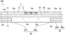
图2是概略地表示图1的II-II线处的车辆用灯具的截面的图。Fig. 2 is a diagram schematically showing a cross-section of the vehicle lamp taken along line II-II in Fig. 1 .
图3是概略地表示作为一次成形体的第一树脂部和第三树脂部的主视图。Fig. 3 is a front view schematically showing a first resin part and a third resin part as a primary molded body.
图4是概略地表示作为二次成形体的第二树脂部的主视图。Fig. 4 is a front view schematically showing a second resin portion as a secondary molded body.
图5是放大地表示图2中的浇口痕迹的附近的截面图。FIG. 5 is an enlarged cross-sectional view showing the vicinity of a gate trace in FIG. 2 .
图6是表示将作为一次成形体的第一树脂部和第三树脂部成形的状态的一例的概略的截面图。6 is a schematic cross-sectional view showing an example of a state in which a first resin portion and a third resin portion as a primary molded body are molded.
图7是表示将作为二次成形体的第二树脂部成形的状态的一例的概略的截面图。7 is a schematic cross-sectional view showing an example of a state in which a second resin portion as a secondary molded body is molded.
图8是放大地表示变形例的外罩的一部分的主视图。Fig. 8 is an enlarged front view showing a part of a cover of a modified example.
符号说明Symbol Description
1外罩(罩体)1 outer cover (cover body)
2多色成形体2 multi-color moldings
3密封件3 seals
10第一树脂部10The first resin department
10S1第一树脂部的外部侧的面10S1 The outer side surface of the first resin part
15a~15g浇口痕迹15a~15g gate marks
20第二树脂部20 Second Resin Department
20S1第二树脂部的外部侧的面20S1 The surface on the outer side of the second resin part
25、125台阶部25, 125 steps
26倾斜面26 inclined surfaces
30第三树脂部30 The third resin department
具体实施方式detailed description
以下,与附图一同例示用于实施本发明的罩体的方式。以下例示的实施方式用于使本发明的理解变得容易,并不用于限定解释本发明。本发明在不脱离其主旨的情况下,能够从以下的实施方式进行变更、改良。另外,在上述附图中,为了容易理解,有时夸张地表示各部件的尺寸。Hereinafter, the form for implementing the cover body of this invention is illustrated with drawing. The embodiments illustrated below are for facilitating understanding of the present invention, and are not intended to limit the interpretation of the present invention. The present invention can be changed and improved from the following embodiments without departing from the gist. In addition, in the above-mentioned drawings, the size of each component may be exaggerated for easy understanding.
图1是概略地表示具备本发明的实施方式的罩体的车辆用灯具的主视图。图2是概略地表示图1的II-II线处的车辆用灯具的截面的图。本实施方式的车辆用灯具100是汽车用的标识灯,具体而言,是将尾灯、刹车灯和倒车灯一体化的后组合灯。FIG. 1 is a front view schematically showing a vehicle lamp including a cover according to an embodiment of the present invention. Fig. 2 is a diagram schematically showing a cross-section of the vehicle lamp taken along line II-II in Fig. 1 . The
如图1、图2所示,本实施方式的车辆用灯具100是大致左右对称的结构,作为主要的结构,具备壳体70、第一光源81、两个第二光源82、第一反射镜85、以及第二反射镜86。作为主要的结构,壳体70具备作为罩体的外罩1和灯外壳71。灯外壳71构成为具有一个开口的箱状,外罩1被固定于灯外壳71以封堵该开口。由灯外壳71和外罩1形成的空间为灯室70R,在该灯室70R内收纳有第一光源81、两个第二光源82、第一反射镜85、以及第二反射镜86。As shown in FIGS. 1 and 2 , the
作为本实施方式的罩体的外罩1具备多色成形体2、以及粘贴于多色成形体2的密封件3。在本实施方式中,多色成形体2的形状是沿上下和左右延伸且在左右方向上呈长条状的板状形状,多色成形体2的厚度大致均匀。多色成形体2包含颜色相互不同的第一树脂部10、第二树脂部20、以及第三树脂部30,第一树脂部10和第三树脂部30为一次成形体,第二树脂部20为二次成形体。第一树脂部10和第三树脂部30具有透光性,第一树脂部10为红色,第三树脂部30为无色透明。第二树脂部20的颜色为黑色,第二树脂部20的透光性比第一树脂部10低。作为第一树脂部10、第二树脂部20、以及第三树脂部30的材料,例如,列举丙烯酸树脂。The cover 1 which is the cover body of this embodiment is equipped with the multi-color molded
图3是概略地表示作为一次成形体的第一树脂部10和第三树脂部30的主视图,是从外部侧正面观察第一树脂部10和第三树脂部30的图。如图2、图3所示,本实施方式的第一树脂部10由沿上下左右延伸且在左右方向上呈长条状的板状的主部11、与主部11的上侧缘部连接的上侧凸缘部12、以及与主部11的下侧缘部连接的下侧凸缘部13构成。上侧凸缘部12的内部侧的面以及下侧凸缘部13的内部侧的面与主部11的内部侧的面连接,通过这些面形成第一树脂部10的背面即内部侧的面10S2。上侧凸缘部12以及下侧凸缘部13的厚度比主部11薄,在作为第一树脂部10的表面的外部侧的面10S1,在主部11与上侧凸缘部12之间以及在主部11与下侧凸缘部13之间形成有台阶部。上侧凸缘部12以及下侧凸缘部13的厚度例如为1.8mm~2.6mm左右,主部11的厚度例如为2.6mm~3.2mm左右。在作为第一树脂部10的外部侧的面10S1的一部分的上侧凸缘部12的外部侧的面形成有五个浇口痕迹15a~15e,这些浇口痕迹15a~15e在左右方向上隔开间隔地排列。另外,在作为面10S1的另一部分的下侧凸缘部13的外部侧的面沿左右方向隔开间隔地形成有两个浇口痕迹15f~15g。这七个浇口痕迹15a~15g为凹状的凹陷,形状大致相同,外缘的形状大致为圆形,表面与球面的一部分大致相同。浇口痕迹的深度例如为0.7mm~0.8mm左右。此外,浇口痕迹15a~15g的形状没有特别限制,例如,也可以是凹陷成圆锥状的形状。3 is a front view schematically showing the
本实施方式的第三树脂部30由右侧树脂部30R和左侧树脂部30L构成。右侧树脂部30R和左侧树脂部30L在左右方向上配置于相互大致对称的位置,右侧树脂部30R和左侧树脂部30L的形状为在左右方向上相互大致对称的形状。因此,对左侧树脂部30L进行说明,关于右侧树脂部30R的说明省略。左侧树脂部30L配置在第一树脂部10的下方且相比第一树脂部10的左右方向的中心位于左侧。左侧树脂部30L由沿上下左右延伸且在左右方向上呈长条状的板状的主部31和与主部31的缘部连接的凸缘部32构成。凸缘部32遍及主部31的上侧缘部、右侧缘部以及下侧缘部而连续地延伸。凸缘部32的内部侧的面与主部31的内部侧的面连接,通过这些面形成第三树脂部30的背面即内部侧的面30S2。凸缘部32的厚度比主部31薄,在作为第三树脂部30的表面的外部侧的面30S1,在主部31与凸缘部32之间形成有台阶部。主部31的厚度例如与第一树脂部10的主部11的厚度相同,凸缘部32的厚度例如与第一树脂部10的上侧凸缘部12的厚度相同。The
图4是概略地表示作为二次成形体的第二树脂部20的主视图,是从外部侧正面观察第二树脂部20的图。此外,在图4中,利用虚线表示第一树脂部10和第三树脂部30。如图2、图4所示,本实施方式的第二树脂部20由沿上下左右延伸且在左右方向上呈长条状的板状的上侧树脂部20U以及配置在上侧树脂部20U的下方的沿上下左右延伸且在左右方向上呈长条状的板状的下侧树脂部20D构成。上侧树脂部20U从外部侧覆盖第一树脂部10中的上侧凸缘部12的整体,并粘接于上侧凸缘部12的外部侧的面。因此,上侧凸缘部12的外部侧的面所具有的五个浇口痕迹15a~15e被上侧树脂部20U覆盖。上侧树脂部20U的下侧缘部与第一树脂部10中的主部11的上侧缘部的整体连接,上侧树脂部20U的外部侧的面与主部11的外部侧的面连接。下侧树脂部20D从外部侧覆盖下侧凸缘部13的整体和凸缘部32的整体,并粘接于该下侧凸缘部13和凸缘部32的外部侧的面。因此,下侧凸缘部13的外部侧的面所具有的两个浇口痕迹15f~15g被下侧树脂部20D覆盖。另外,上下方向上的第一树脂部10与第三树脂部30的间隙被下侧树脂部20D填埋,第一树脂部10与第三树脂部30由下侧树脂部20D连接,第一树脂部10、第二树脂部20以及第三树脂部30成为一体。另外,下侧树脂部20D的外周缘部的一部分与主部11的下侧缘部的整体连接,下侧树脂部20D的外部侧的面与主部11的外部侧的面连接。另外,下侧树脂部20D的外周缘部的另一部分与左侧树脂部30L中的主部31的上侧缘部、右侧缘部和下侧缘部的整体、以及右侧树脂部30R中的主部31的上侧缘部、左侧缘部和下侧缘部的整体连接。并且,下侧树脂部20D的外部侧的面与左侧树脂部30L和右侧树脂部30R中的主部31的外部侧的面连接。这样的第二树脂部20不覆盖第一树脂部10的主部11以及右侧树脂部30R和左侧树脂部30L中的主部31,第二树脂部20与这些主部11、31露出到外部侧。FIG. 4 is a front view schematically showing the
图5是放大地表示图2中的浇口痕迹15a的附近的截面图。如图4、图5所示,上侧树脂部20U的外部侧的面具有台阶部25。在本实施方式中,台阶部25从该面的右侧的边缘呈直线状延伸到左侧的边缘。另外,该台阶部25由倾斜面26形成。该倾斜面26相对于作为第一树脂部10的外部侧的面10S1的一部分的上侧凸缘部12的外部侧的面,以朝向上方接近上侧凸缘部12的方式倾斜。因此,上侧树脂部20U中的比台阶部25靠上侧的厚度相比于比该台阶部25靠下侧的厚度薄。如图4所示,在正面观察上侧树脂部20U的外部侧的面时,这样的台阶部25与五个浇口痕迹15a~15e重叠。另外,在这样观察时的倾斜面26的倾斜方向上的台阶部25的宽度25w比与该台阶部25重叠的各个浇口痕迹15a~15e中的最大宽度小,例如为0.5mm以下。这样的台阶部25横穿各个浇口痕迹15a~15e。另外,台阶部25与各个浇口痕迹15a~15e的中心C重叠。更具体而言,倾斜面26的倾斜方向上的一侧的边缘26e1与浇口痕迹15a~15e的中心C重叠。该一侧的边缘26e1相比倾斜面26的倾斜方向上的另一侧的边缘26e2更接近第一树脂部10。另外,台阶部25的高度25h比浇口痕迹15a~15e的深度15D小,例如为0.1mm~0.3mm左右。此外,台阶部25的高度25h为与台阶部25附近处的上侧凸缘部12的外部侧的面垂直的方向上的高度。另外,台阶部25的高度25h也可以是浇口痕迹15a~15e的深度15D以上。FIG. 5 is an enlarged cross-sectional view showing the vicinity of the
接下来,对本实施方式的外罩1中的多色成形体2的制造方法进行说明。Next, a method for manufacturing the multicolor molded
图6是表示将作为一次成形体的第一树脂部10和第三树脂部30成形的状态的一例的概略的截面图,是穿过形成浇口痕迹15a的浇口的截面。如图6所示,第一树脂部10和第三树脂部30是使用被固定的第一金属模41和能够相对于第一金属模41移动的第二金属模42而形成的。在将第二金属模42按压于第一金属模41而将第一金属模41和第二金属模42对合的状态下,在第一金属模41与第二金属模42之间形成有与第一树脂部10对应的空间51以及与第三树脂部30对应的空间53。在第二金属模42中,在与第一树脂部10对应的位置形成有七个直接浇口45。另外,在第二金属模42中,在与第三树脂部30的右侧树脂部30R和左侧树脂部30L分别对应的位置形成有侧浇口。此外,在图3中,用箭头A表示与这些侧浇口对应的位置,在图6中,用虚线表示与左侧树脂部30L对应的侧浇口46。这样,在将第一金属模41与第二金属模42对合的状态下,将构成第一树脂部10的熔融状态的树脂从直接浇口45注射到空间51而填充于该空间51。然后,通过未图示的浇口销的前端部来封堵直接浇口45而对所填充的熔融状态的树脂进行保压。另外,将构成第三树脂部30的熔融状态的树脂从侧浇口46注射到空间53而填充于该空间53,对所填充的熔融状态的树脂进行保压。通过像这样使分别填充于空间51、53的熔融状态的树脂冷却而固化,从而成形作为一次成形体的第一树脂部10和第三树脂部30。此时,在第一树脂部10中,由于封堵直接浇口45的浇口销的前端部而形成上述的浇口痕迹15a~15g,浇口痕迹15a~15g的形状与该前端部的形状大致对应。此外,将构成第一树脂部10的熔融状态的树脂注射到空间51的浇口的位置、以及将构成第三树脂部30的熔融状态的树脂注射到空间53的浇口的位置没有特别限制。接着,将第二金属模42更换为第三金属模而成形作为二次成形体的第二树脂部20。6 is a schematic cross-sectional view showing an example of a state in which the
图7是概略地表示将第二树脂部20成形的状态的一例的截面图,是与图6相同的位置处的截面图。如图7所示,在将第三金属模43按压于第一金属模41而第一金属模41与第三金属模43对合的状态下,在第一金属模41与第三金属模43之间形成有与第二树脂部20对应的空间52。在第三金属模43中,在与第二树脂部20对应的位置形成有多个侧浇口47。此外,在图4中,用箭头B表示与这些侧浇口47对应的位置。这样,在将第一金属模41与第三金属模43对合的状态下,将构成第二树脂部20的熔融状态的树脂从侧浇口47注射到空间52而填充于该空间52,对所填充的熔融状态的树脂进行保压。通过使填充于空间52的熔融状态的树脂冷却而固化,从而成形作为二次成形体的第二树脂部20,制造出多色成形体2。此外,将构成第二树脂部20的熔融状态的树脂注射到空间52的浇口的位置没有特别限制。FIG. 7 is a cross-sectional view schematically showing an example of a state in which the
接下来,返回图1,对密封件3进行说明。本实施方式的密封件3粘贴于作为多色成形体2中的第二树脂部20的外部侧的面20S1的一部分的上侧树脂部20U的外部侧的面。在密封件3描绘有多个字符。通过该密封件3,在外罩1描绘有位于第二树脂部20的远离第一树脂部10的一侧且能够从外部目视确认的字符。本实施方式的字符为白色的“A”“B”和“C”的文字,“B”与浇口痕迹15c重叠。此外,字符只要是图形、符号以及文字等即可,字符的数量、颜色没有特别限制。作为密封件3,例如,能够列举这样的层叠体,该层叠体具有无色透明的基材层、在该基材层的一个面上形成的印刷层、在基材层的另一个面上形成的无色透明的粘接剂层,通过印刷层来描绘字符。Next, returning to FIG. 1 , the
图1、图2所示的第一光源81射出作为尾灯的光或者作为刹车灯的光。在本实施方式中,第一光源81是将多个LED(Light Emitting Diode:发光二极管)在左右方向上排列而得的所谓LED阵列,各个LED射出白色的光。第一光源81被配置为与第一树脂部10中的主部11相对,从第一光源81射出的光透过主部11而向外部射出。由于第一树脂部10为红色,因此从第一光源81射出的光中的红色成分的光向外部射出。另外,第一光源81的周围被第一反射镜85包围,以使从第一光源81射出的光有效地入射到主部11。另外,通过该第一反射镜85而抑制从第一光源81射出的光入射到第三树脂部30中的主部31。The
两个第二光源82射出作为倒车灯的光。在本实施方式中,第二光源82是将多个LED在左右方向上排列而得的所谓LED阵列,各个LED射出白色的光。一个第二光源82被配置为与第三树脂部30的右侧树脂部30R中的主部31相对,另一个第二光源82被配置为与左侧树脂部30L中的主部31相对。从各个第二光源82射出的光透过主部31而向外部射出。第三树脂部30为无色,因此从第一光源81射出的白色的光向外部射出。另外,各个第二光源82的周围被第二反射镜86包围,以使从第二光源82射出的光有效地入射到主部31。另外,通过该第二反射镜86而抑制从第二光源82射出的光入射到第一树脂部中的主部11。The two second
像以上说明的那样,作为本实施方式的罩体的外罩1具备多色成形体2。多色成形体2包含:在外部侧的面10S1具有浇口痕迹15a~15g的第一树脂部10以及为与第一树脂部10不同的颜色且粘接于第一树脂部10的外部侧的面10S1并覆盖浇口痕迹15a~15g的第二树脂部20。第二树脂部20的外部侧的面20S1具有与浇口痕迹15a~15e重叠的台阶部25。因此,即使在第二树脂部20中的覆盖第一树脂部10的浇口痕迹15a~15e的部位及其周围的外部侧的面20S1产生缩痕的情况下,也能够将该缩痕与台阶部25重叠。因此,根据本实施方式的外罩1,通过该台阶部25能够使该缩痕不明显,能够抑制外观性的降低。As described above, the cover 1 as the cover body of the present embodiment includes the multi-color molded
另外,在本实施方式的外罩1中,台阶部25横穿浇口痕迹15a~15e。因此,根据本实施方式的外罩1,在第二树脂部20的外部侧的面20S1出现的台阶部25能够横穿缩痕,与台阶部25位于形成有缩痕的区域内的情况相比,能够使缩痕更不明显。In addition, in the housing 1 of the present embodiment, the stepped
另外,在本实施方式的外罩1中,台阶部25与各个浇口痕迹15a~15e的中心C重叠。缩痕的中心有位于浇口痕迹的中心的正上方的倾向。因此,根据本实施方式的外罩1,台阶部25能够与缩痕的中心重叠,和台阶部25与各个浇口痕迹15a~15e的中心C不重叠的情况相比,能够使缩痕更不明显。Moreover, in the cover 1 of this embodiment, the
另外,在本实施方式的外罩1描绘有文字“B”,该文字“B”是位于第二树脂部20的远离第一树脂部10的一侧且能够从外部目视确认并与浇口痕迹15c重叠的字符。因此,作为字符的文字“B”能够与缩痕重叠,通过作为字符的文字“B”能够使缩痕更不明显。In addition, on the cover 1 of the present embodiment, the character "B" is drawn, and the character "B" is located on the side of the
另外,本实施方式的外罩1中,台阶部25由倾斜面26形成,该倾斜面26相对于作为第一树脂部10的外部侧的面10S1的一部分的上侧凸缘部12的外部侧的面倾斜,并横穿各个浇口痕迹15a~15e。并且,该倾斜面26的倾斜方向上的一侧的边缘26e1与浇口痕迹15a~15e的中心C重叠。第二树脂部20的外部侧的面20S1在该倾斜面26的边缘处折弯。根据本实施方式的外罩1,第二树脂部20的外部侧的面20S1中的折弯的部位能够与缩痕的中心重叠,与该折弯的部位和缩痕的中心不重叠的情况相比,能够使缩痕更不明显。此外,倾斜面26与浇口痕迹15a~15e的中心C也可以不重叠。然而,从使缩痕更不明显的观点出发,优选倾斜面26与浇口痕迹15a~15e的中心C重叠,更优选倾斜面26的一侧的边缘26e1与浇口痕迹15a~15e的中心C重叠。另外,在本实施方式的外罩1中,倾斜面26相对于上侧凸缘部12的外部侧的面的倾斜角为锐角。因此,根据本实施方式的外罩1,与倾斜面26的倾斜角为大致90度的情况相比,能够使得难以在倾斜面26的倾斜方向上的两侧的边缘产生毛刺。In addition, in the cover 1 of the present embodiment, the stepped
另外,在本实施方式的外罩1中,上述的一侧的边缘26e1相比倾斜面26的倾斜方向上的另一侧的边缘26e2更接近第一树脂部10。因此,与一侧的边缘26e1相比另一侧的边缘26e2更远离第一树脂部10的情况相比,能够使各个浇口痕迹15a~15e的中心C上的第二树脂部20的厚度变薄。因此,根据本实施方式的外罩1,与上述的情况相比能够减小缩痕,能够使缩痕更不明显。此外,也可以使一侧的边缘26e1相比另一侧的边缘26e2更远离第一树脂部10。即使在这样的情况下,第二树脂部20的外部侧的面20S1中的折弯的部位也能够与缩痕的中心重叠,与该折弯的部位和缩痕的中心不重叠的情况相比,能够使缩痕更不明显。In addition, in the cover 1 according to the present embodiment, the above-mentioned one edge 26 e 1 is closer to the
以上,以上述实施方式为例对本发明进行了说明,但本发明不限于此。As mentioned above, although this invention was demonstrated using the said embodiment as an example, this invention is not limited to this.
例如,在上述实施方式中,以包含颜色相互不同的第一树脂部10、第二树脂部20以及第三树脂部30的多色成形体2为例进行了说明。然而,多色成形体2只要包含颜色相互不同的第一树脂部10和第二树脂部20即可,例如,多色成形体2也可以不包含第三树脂部30。另外,包含第一树脂部10和第二树脂部20的树脂部的颜色也没有特别限制。例如,在上述实施方式中,也可以采用如下的结构,第三树脂部30为具有透光性的橙色,两个第二光源82作为转向灯而射出光。由此,能够使车辆用灯具100成为将尾灯和刹车灯与转向灯一体化的后组合灯。如此,使用外罩1的车辆用灯具没有特别限制。For example, in the above-mentioned embodiment, the multicolor molded
另外,在上述实施方式中,作为罩体,以车辆用灯具100所使用的外罩1为例进行了说明。然而,罩体没有特别限制。例如,罩体也可以是收纳毫米波雷达、激光雷达(LiDAR)等的传感器的壳体的一部分,在该情况下,罩体中的多色成形体也可以是由透光性低的多个树脂部构成的无法从外部目视确认内部的结构。In addition, in the above-described embodiment, the cover 1 used for the
另外,在上述实施方式中,以在外部侧的面10S1具有七个浇口痕迹15a~15g的第一树脂部10为例进行了说明。然而,浇口痕迹的数量没有特别限制,例如也可以是一个。In addition, in the said embodiment, the
另外,在上述实施方式中,以呈直线状延伸而横穿五个浇口痕迹15a~15e的台阶部25为例进行了说明。然而,台阶部25只要与浇口痕迹重叠即可,与台阶部25重叠的浇口痕迹的数量没有特别限制。例如,台阶部25也可以呈曲线状延伸而横穿多个浇口痕迹。另外,也可以是,台阶部25的整体与一个浇口痕迹的一部分重叠,作为这样的台阶部25,例如,能够列举由槽形成的台阶部。另外,第二树脂部20的外部侧的面20S1所具有的台阶部25的数量没有特别限制。例如,在上述实施方式中,该面20S1也可以进一步具有呈直线状延伸而与两个浇口痕迹15f~15g重叠的其他的台阶部。另外,也可以是,面20S1具有与浇口痕迹的数量相同数量的台阶部25,各个台阶部25与相互不同的浇口痕迹重叠,多个台阶部也可以与相同的浇口痕迹重叠。In addition, in the said embodiment, the step|step-
另外,在上述实施方式中,台阶部25由相对于第一树脂部10的外部侧的面10S1倾斜的倾斜面26形成。然而,台阶部25也可以由与外部侧的面10S1大致垂直的面形成。In addition, in the above-described embodiment, the stepped
另外,在上述实施方式中,以通过粘贴于多色成形体2的密封件3来描绘能够从外部目视确认的字符的外罩1为例进行了说明。然而,字符只要位于第二树脂部20的远离第一树脂部10的一侧且能够从外部目视确认即可,例如,字符的至少一部分也可以通过台阶部25来描绘。图8是放大地表示变形例的外罩的一部分的主视图。图8所示的变形例的外罩1在还具备与台阶部25不同的台阶部125这一点上与上述实施方式的外罩1不同,该台阶部125在配置不同这一点上与台阶部25不同。在本变形例中,作为第二树脂部20的外部侧的面20S1的一部分的下侧树脂部20D中的外部侧的面具有台阶部125。台阶部125以描绘四边形的方式延伸,横穿两个浇口痕迹15f~15g。下侧树脂部20D的外部侧的面中的由台阶部125包围的区域相比其他的区域更接近第一树脂部10侧。这样,在本变形例的外罩1上,通过台阶部125来描绘作为字符的四边形,作为该字符的四边形位于第二树脂部20的远离第一树脂部10的一侧,且与两个浇口痕迹15f~15g重叠。即使是作为这样的字符的四边形,也能够使第二树脂部20的外部侧的面20S1的缩痕不明显。此外,也可以通过第二树脂部20的外部侧的面20S1所具有的台阶部来描绘字符的一部分,通过粘贴于该面20S1的密封件来描绘字符的另一部分。另外,在第二树脂部20具有透光性的情况下,例如,也可以是,在第二树脂部20的内部配置描绘有字符的密封件,该字符能够从外部目视确认且与浇口痕迹重叠。In addition, in the above-mentioned embodiment, the cover 1 in which the characters visually recognizable from the outside are drawn by the
产业上的可利用性Industrial availability
根据本发明,提供能够抑制外观性的降低的罩体,能够在汽车等的车辆用灯具的壳体等领域中利用。According to the present invention, a cover capable of suppressing deterioration in appearance is provided, and can be used in fields such as housings for vehicle lamps such as automobiles.
Claims (10)
Translated fromChineseApplications Claiming Priority (2)
| Application Number | Priority Date | Filing Date | Title |
|---|---|---|---|
| JP2021-096142 | 2021-06-08 | ||
| JP2021096142AJP7659445B2 (en) | 2021-06-08 | 2021-06-08 | Cover body |
Publications (1)
| Publication Number | Publication Date |
|---|---|
| CN115451378Atrue CN115451378A (en) | 2022-12-09 |
Family
ID=84284997
Family Applications (1)
| Application Number | Title | Priority Date | Filing Date |
|---|---|---|---|
| CN202210644081.3APendingCN115451378A (en) | 2021-06-08 | 2022-06-08 | Cover |
Country Status (3)
| Country | Link |
|---|---|
| US (1) | US12163639B2 (en) |
| JP (1) | JP7659445B2 (en) |
| CN (1) | CN115451378A (en) |
Families Citing this family (2)
| Publication number | Priority date | Publication date | Assignee | Title |
|---|---|---|---|---|
| JP2024138900A (en)* | 2023-03-27 | 2024-10-09 | 株式会社小糸製作所 | Vehicle lighting fixtures |
| EP4600012A1 (en)* | 2024-02-12 | 2025-08-13 | ZKW Group GmbH | Two-material injection molding method |
Citations (4)
| Publication number | Priority date | Publication date | Assignee | Title |
|---|---|---|---|---|
| JPH082574A (en)* | 1994-06-21 | 1996-01-09 | Mitsubishi Materials Corp | Transparent case and molding die device therefor |
| US5721039A (en)* | 1993-05-18 | 1998-02-24 | Koito Manufacturing Co., Ltd. | Synthetic resin layered lens for a vehicle lighting device, method of molding the same and apparatus therefore |
| JP2004014423A (en)* | 2002-06-11 | 2004-01-15 | Koito Mfg Co Ltd | Vehicle lighting |
| JP2011187299A (en)* | 2010-03-08 | 2011-09-22 | Koito Mfg Co Ltd | Lens of lighting fixture for vehicle |
Family Cites Families (2)
| Publication number | Priority date | Publication date | Assignee | Title |
|---|---|---|---|---|
| JP2003022704A (en) | 2001-07-10 | 2003-01-24 | Koito Mfg Co Ltd | Lighting fixture for vehicle |
| WO2018180351A1 (en) | 2017-03-30 | 2018-10-04 | 本田技研工業株式会社 | Headlight device for saddle-type vehicle |
- 2021
- 2021-06-08JPJP2021096142Apatent/JP7659445B2/enactiveActive
- 2022
- 2022-06-03USUS17/831,823patent/US12163639B2/enactiveActive
- 2022-06-08CNCN202210644081.3Apatent/CN115451378A/enactivePending
Patent Citations (4)
| Publication number | Priority date | Publication date | Assignee | Title |
|---|---|---|---|---|
| US5721039A (en)* | 1993-05-18 | 1998-02-24 | Koito Manufacturing Co., Ltd. | Synthetic resin layered lens for a vehicle lighting device, method of molding the same and apparatus therefore |
| JPH082574A (en)* | 1994-06-21 | 1996-01-09 | Mitsubishi Materials Corp | Transparent case and molding die device therefor |
| JP2004014423A (en)* | 2002-06-11 | 2004-01-15 | Koito Mfg Co Ltd | Vehicle lighting |
| JP2011187299A (en)* | 2010-03-08 | 2011-09-22 | Koito Mfg Co Ltd | Lens of lighting fixture for vehicle |
Also Published As
| Publication number | Publication date |
|---|---|
| US20220390084A1 (en) | 2022-12-08 |
| JP2022187909A (en) | 2022-12-20 |
| US12163639B2 (en) | 2024-12-10 |
| JP7659445B2 (en) | 2025-04-09 |
Similar Documents
| Publication | Publication Date | Title |
|---|---|---|
| JP6134484B2 (en) | Vehicle rear panel | |
| US9506619B2 (en) | Signaling lamps for motor vehicle | |
| JP6607146B2 (en) | Luminous emblem | |
| CN115451378A (en) | Cover | |
| JP6371100B2 (en) | Two-color molding method | |
| US20170355302A1 (en) | Display apparatus and manufacturing method thereof | |
| US20140003076A1 (en) | Vehicular lamp and window unit | |
| US10583597B2 (en) | Resin-molded component | |
| JP6199144B2 (en) | Lighting device | |
| CN109305121B (en) | radio wave transmission cover | |
| US11597449B2 (en) | Vehicle outer plate panel and method for manufacturing vehicle outer plate panel | |
| CN105283354B (en) | The steering indicating light component and Vehicular door rear mirror of Vehicular door rear mirror | |
| JP7579709B2 (en) | Vehicle lighting fixtures | |
| US20140307476A1 (en) | Multilayer license plate lighting apparatus | |
| JP2017112039A (en) | Window rear lamp | |
| CN115398146A (en) | Lighting device and method for connecting a lighting device | |
| JP6674143B2 (en) | Decorative parts | |
| JP2015094905A (en) | Display device | |
| JP2017174726A (en) | Window panel with vehicular lighting fixture and rear panel for vehicle | |
| JP2018086772A (en) | Indicator panel and two color injection molding method thereof | |
| JP7593299B2 (en) | Vehicle exterior parts | |
| JP7051547B2 (en) | Display device for vehicles | |
| WO2025157658A1 (en) | Lighting assembly and motor vehicle | |
| JP7616149B2 (en) | Luminous Emblem | |
| US20240413289A1 (en) | Optoelectronic device and method |
Legal Events
| Date | Code | Title | Description |
|---|---|---|---|
| PB01 | Publication | ||
| PB01 | Publication | ||
| SE01 | Entry into force of request for substantive examination | ||
| SE01 | Entry into force of request for substantive examination |