CN115451281A - Rotary modules and photography equipment - Google Patents
Rotary modules and photography equipmentDownload PDFInfo
- Publication number
- CN115451281A CN115451281ACN202211091332.6ACN202211091332ACN115451281ACN 115451281 ACN115451281 ACN 115451281ACN 202211091332 ACN202211091332 ACN 202211091332ACN 115451281 ACN115451281 ACN 115451281A
- Authority
- CN
- China
- Prior art keywords
- annular
- rotating shaft
- cages
- rotary module
- module according
- Prior art date
- Legal status (The legal status is an assumption and is not a legal conclusion. Google has not performed a legal analysis and makes no representation as to the accuracy of the status listed.)
- Pending
Links
Images


Classifications
- F—MECHANICAL ENGINEERING; LIGHTING; HEATING; WEAPONS; BLASTING
- F16—ENGINEERING ELEMENTS AND UNITS; GENERAL MEASURES FOR PRODUCING AND MAINTAINING EFFECTIVE FUNCTIONING OF MACHINES OR INSTALLATIONS; THERMAL INSULATION IN GENERAL
- F16M—FRAMES, CASINGS OR BEDS OF ENGINES, MACHINES OR APPARATUS, NOT SPECIFIC TO ENGINES, MACHINES OR APPARATUS PROVIDED FOR ELSEWHERE; STANDS; SUPPORTS
- F16M11/00—Stands or trestles as supports for apparatus or articles placed thereon ; Stands for scientific apparatus such as gravitational force meters
- F16M11/02—Heads
- F16M11/04—Means for attachment of apparatus; Means allowing adjustment of the apparatus relatively to the stand
- F16M11/06—Means for attachment of apparatus; Means allowing adjustment of the apparatus relatively to the stand allowing pivoting
- F—MECHANICAL ENGINEERING; LIGHTING; HEATING; WEAPONS; BLASTING
- F16—ENGINEERING ELEMENTS AND UNITS; GENERAL MEASURES FOR PRODUCING AND MAINTAINING EFFECTIVE FUNCTIONING OF MACHINES OR INSTALLATIONS; THERMAL INSULATION IN GENERAL
- F16C—SHAFTS; FLEXIBLE SHAFTS; ELEMENTS OR CRANKSHAFT MECHANISMS; ROTARY BODIES OTHER THAN GEARING ELEMENTS; BEARINGS
- F16C11/00—Pivots; Pivotal connections
- F16C11/04—Pivotal connections
- F16C11/10—Arrangements for locking
- F—MECHANICAL ENGINEERING; LIGHTING; HEATING; WEAPONS; BLASTING
- F16—ENGINEERING ELEMENTS AND UNITS; GENERAL MEASURES FOR PRODUCING AND MAINTAINING EFFECTIVE FUNCTIONING OF MACHINES OR INSTALLATIONS; THERMAL INSULATION IN GENERAL
- F16C—SHAFTS; FLEXIBLE SHAFTS; ELEMENTS OR CRANKSHAFT MECHANISMS; ROTARY BODIES OTHER THAN GEARING ELEMENTS; BEARINGS
- F16C11/00—Pivots; Pivotal connections
- F16C11/04—Pivotal connections
- F16C11/12—Pivotal connections incorporating flexible connections, e.g. leaf springs
- F—MECHANICAL ENGINEERING; LIGHTING; HEATING; WEAPONS; BLASTING
- F16—ENGINEERING ELEMENTS AND UNITS; GENERAL MEASURES FOR PRODUCING AND MAINTAINING EFFECTIVE FUNCTIONING OF MACHINES OR INSTALLATIONS; THERMAL INSULATION IN GENERAL
- F16M—FRAMES, CASINGS OR BEDS OF ENGINES, MACHINES OR APPARATUS, NOT SPECIFIC TO ENGINES, MACHINES OR APPARATUS PROVIDED FOR ELSEWHERE; STANDS; SUPPORTS
- F16M11/00—Stands or trestles as supports for apparatus or articles placed thereon ; Stands for scientific apparatus such as gravitational force meters
- F16M11/02—Heads
- F16M11/16—Details concerning attachment of head-supporting legs, with or without actuation of locking members thereof
- F—MECHANICAL ENGINEERING; LIGHTING; HEATING; WEAPONS; BLASTING
- F16—ENGINEERING ELEMENTS AND UNITS; GENERAL MEASURES FOR PRODUCING AND MAINTAINING EFFECTIVE FUNCTIONING OF MACHINES OR INSTALLATIONS; THERMAL INSULATION IN GENERAL
- F16M—FRAMES, CASINGS OR BEDS OF ENGINES, MACHINES OR APPARATUS, NOT SPECIFIC TO ENGINES, MACHINES OR APPARATUS PROVIDED FOR ELSEWHERE; STANDS; SUPPORTS
- F16M11/00—Stands or trestles as supports for apparatus or articles placed thereon ; Stands for scientific apparatus such as gravitational force meters
- F16M11/02—Heads
- F16M11/18—Heads with mechanism for moving the apparatus relatively to the stand
Landscapes
- Engineering & Computer Science (AREA)
- General Engineering & Computer Science (AREA)
- Mechanical Engineering (AREA)
- Accessories Of Cameras (AREA)
Abstract
Description
Translated fromChinese技术领域technical field
本发明涉及摄影器材技术领域,特别涉及一种旋转模组和摄影设备。The invention relates to the technical field of photographic equipment, in particular to a rotary module and photographic equipment.
背景技术Background technique
随着生活水平的提高,摄影逐渐成为越来越多人的业余爱好。在手持拍摄、稳定器拍摄、肩抗拍摄以及三脚架拍摄过程中,为了方便拍摄,往往需要装配摄影件完成手动旋转拍摄,如魔术转接头、快拆板、手柄、三脚架和上手提等,手柄和上手提可以用来调节不同角度的场景拍摄,但是现有的手柄或者上手提等摄影件在装配锁紧固定后,不能快速的对摄影设备的拍摄角度进行转动调节,无法让用户快速调节所需拍摄角度。With the improvement of living standards, photography has gradually become a hobby for more and more people. In the process of hand-held shooting, gimbal shooting, shoulder-resistant shooting and tripod shooting, in order to facilitate shooting, it is often necessary to assemble photographic parts to complete manual rotation shooting, such as magic adapters, quick-release plates, handles, tripods and upper handles, etc. The handle and The upper handle can be used to adjust the scene shooting at different angles, but after the existing handles or upper handles are assembled and locked, they cannot quickly rotate and adjust the shooting angle of the photographic equipment, and it is impossible for the user to quickly adjust the desired angle. Filming angle.
发明内容Contents of the invention
本发明提供一种旋转模组和摄影设备,旨在实现快速的对摄影设备的拍摄角度进行转动调节,方便用户快速调节所需的拍摄角度。The invention provides a rotating module and a photographic device, aiming at realizing rapid rotational adjustment of the shooting angle of the photographic device, so as to facilitate users to quickly adjust the required shooting angle.
为实现上述目的,本发明提出的旋转模组,应用于摄影件,包括:In order to achieve the above purpose, the rotating module proposed by the present invention is applied to photographic documents, including:
外壳,所述外壳设有安装孔;a shell, the shell is provided with mounting holes;
两个环形保持架,沿所述安装孔的轴向依次转动设于所述安装孔内;Two annular cages are arranged in the installation hole sequentially rotating along the axial direction of the installation hole;
转轴,穿插于两所述环形保持架中;The rotating shaft is interspersed in the two annular cages;
传动组件,两所述环形保持架经所述传动组件传动配合,所述传动组件用于在一所述环形保持架转动时,带动另一所述环形保持架向相反方向转动;A transmission assembly, the two annular cages are driven and matched through the transmission assembly, and the transmission assembly is used to drive the other annular cage to rotate in the opposite direction when one of the annular cages rotates;
所述环形保持架设有沿其周向分布的多个安装槽,所述转轴在对应两个所述环形保持架的外周壁均设有凸起的抵接部,所述安装槽中设有滚动件,一所述环形保持架对应的抵接部的凸起高度均沿所述转轴的第一周向逐渐增大,另一所述环形保持架对应的抵接部的凸起高度均沿所述转轴的第一周向逐渐减小,所述滚动件设置在抵接部与所述安装孔内壁之间。The annular cage is provided with a plurality of mounting grooves distributed along its circumference, and the rotating shaft is provided with protruding abutting parts on the outer peripheral walls corresponding to two of the annular cages, and rolling grooves are provided in the mounting grooves. The protrusion height of the abutting portion corresponding to one of the annular cages increases gradually along the first circumferential direction of the rotating shaft, and the protrusion height of the abutting portion corresponding to the other annular cage increases along the first circumferential direction of the rotating shaft. The first circumferential direction of the rotating shaft gradually decreases, and the rolling element is arranged between the abutting portion and the inner wall of the installation hole.
在一些实施例中,所述转轴的外周壁对应每一环形保持架还分别设有环形凸起,所述环形凸起与所述转轴同轴,所述环形凸起的高度大于所述抵接部的最大凸起高度,所述滚动件包括至少两个滚动体,每一所述滚动件的至少两个滚动体分别卡在对应的环形凸起的轴向上的两侧;或者,In some embodiments, the outer peripheral wall of the rotating shaft is provided with an annular protrusion corresponding to each annular cage, the annular protrusion is coaxial with the rotating shaft, and the height of the annular protrusion is greater than the abutment The maximum protrusion height of the section, the rolling element includes at least two rolling elements, and the at least two rolling elements of each rolling element are respectively stuck on both sides of the corresponding annular protrusion in the axial direction; or,
至少部分安装槽中设有至少一个分隔部,所述至少一个分隔部将其所在所述安装槽分隔成沿所述环形保持架轴向排布的至少两个槽段。At least one partition is provided in at least some of the installation grooves, and the at least one partition divides the installation groove where it is located into at least two groove segments arranged axially along the annular cage.
在一些实施例中,所述滚动件为滚珠,或所述滚动件为轴心与所述转轴的轴心平行的圆柱。In some embodiments, the rolling element is a ball, or the rolling element is a cylinder whose axis is parallel to the axis of the rotating shaft.
在一些实施例中,所述安装孔的孔壁和/或所述抵接部上设有适配所述滚珠的滚道。In some embodiments, the hole wall of the installation hole and/or the abutting portion is provided with a raceway adapted to the ball.
在一些实施例中,所述外壳的两端分别设有与所述安装孔同轴的限位台阶,两所述环形保持架相互远离的一端均设有环形卡边,两所述环形保持架的环形卡边分别适配卡在所述外壳两端的限位台阶中。In some embodiments, the two ends of the housing are respectively provided with limiting steps coaxial with the installation hole, and the ends of the two annular cages far away from each other are provided with annular card edges, and the two annular cages are The annular clamping edges of the rings are adapted to be clamped in the limit steps at both ends of the housing.
在一些实施例中,至少一所述环形保持架靠近所述安装孔端口的一端设有手持部。In some embodiments, at least one end of the annular cage close to the port of the installation hole is provided with a handle.
在一些实施例中,所述传动组件包括传动锥齿轮,所述传动锥齿轮位于两所述环形保持架之间,两所述环形保持架相互靠近的一端均设有锥齿轮面,所述传动锥齿轮转动安装于所述转轴的外周壁上,所述传动锥齿轮与两所述环形保持架的锥齿轮面均啮合。In some embodiments, the transmission assembly includes a transmission bevel gear, and the transmission bevel gear is located between the two ring cages, and the ends of the two ring cages that are close to each other are provided with bevel gear surfaces. The bevel gear is rotatably mounted on the outer peripheral wall of the rotating shaft, and the transmission bevel gear meshes with the bevel gear surfaces of the two annular cages.
在一些实施例中,所述安装孔的内壁还设有环形避让槽,所述环形避让槽与所述传动锥齿轮位置正对。In some embodiments, the inner wall of the installation hole is further provided with an annular avoidance groove, and the annular avoidance groove is directly opposite to the position of the transmission bevel gear.
在一些实施例中,所述旋转模组还包括弹簧件,所述弹簧件位于所述转轴的一侧,所述弹簧件的一端连接所述环形保持架,另一端连接所述外壳,所述弹簧件驱动所述滚动件抵接所述抵接部以及所述外壳,以使得所述转轴与所述外壳锁定。In some embodiments, the rotary module further includes a spring member, the spring member is located on one side of the rotating shaft, one end of the spring member is connected to the ring cage, and the other end is connected to the housing, the The spring element drives the rolling element to abut against the abutting portion and the housing, so that the rotating shaft is locked with the housing.
在一些实施例中,所述外壳包括:In some embodiments, the housing includes:
含有所述安装孔的桶体,所述桶体的一端敞口设置;以及,a barrel body containing the installation hole, one end of the barrel body is open; and,
盖体,所述盖体盖设于所述桶体的敞口端,所述盖体设有避让孔,所述转轴具有从所述避让孔伸出所述外壳的第一连接部,所述第一连接部用于连接第一摄影件;所述桶体远离所述盖体的一端设有第二连接部,所述第二连接部用于连接第二摄影件。A cover body, the cover body cover is arranged on the open end of the barrel body, the cover body is provided with an avoidance hole, and the rotating shaft has a first connecting part protruding from the outer shell from the avoidance hole, the The first connecting portion is used for connecting the first photographic piece; the end of the barrel body away from the cover is provided with a second connecting portion, and the second connecting portion is used for connecting the second photographic piece.
在一些实施例中,所述抵接部到所述转轴轴心的最大距离与最小距离的差值为L;In some embodiments, the difference between the maximum distance and the minimum distance between the abutting portion and the shaft center is L;
所述L为0.3~1.5mm;和/或,The L is 0.3-1.5mm; and/or,
所述滚动件的半径为0.3~20mm;和/或,The radius of the rolling element is 0.3-20mm; and/or,
所述L与所述滚动件半径的比值为0.1~0.6;和/或,The ratio of the L to the radius of the rolling element is 0.1-0.6; and/or,
所述安装孔的直径为R,所述L与所述R的比值为0.012~0.05。The diameter of the mounting hole is R, and the ratio of L to R is 0.012˜0.05.
本发明还提出一种摄影设备,包括如上所述的旋转模组;The present invention also proposes a photographic device, including the above-mentioned rotating module;
第一摄影件,与所述旋转模组的转轴连接;以及The first photographic element is connected to the rotating shaft of the rotating module; and
第二摄影件,与所述外壳连接。The second photographic element is connected with the casing.
本发明旋转模组的技术方案,采用在外壳的安装孔中转动设置两个环形保持架,在环形保持架中插设转轴,环形保持架周向设置安装有滚动件的安装槽,转轴外壁设置与滚动件对应的抵接部,两个环形保持架对应的抵接部的凸起高度的增大方向相反,并且两环形保持架经传动组件传动配合;如此,通过转动一个环形保持架,带动另一个环形保持架异向转动,使滚动件移动至抵紧在抵接部与安装孔内壁之间,即可实现旋转模组的锁定;以及通过转动一个环形保持架,带动另一个环形保持架异向转动,使滚动件移动至与抵接部和安装孔内壁的脱离抵紧状态,即可实现旋转模组的解锁。因此,本发明的旋转模组应用作为摄像件之间的连接件时,可使摄像件之间快速进行角度调节和角度锁定,更加方便用户快速调节所需的拍摄角度。The technical scheme of the rotary module of the present invention adopts two ring-shaped cages to be rotated in the mounting holes of the shell, and a rotating shaft is inserted in the ring-shaped cages. The ring cage is provided with mounting grooves for installing rolling parts in the circumferential direction, and the outer wall of the rotating shaft is arranged For the abutting part corresponding to the rolling element, the increasing direction of the protrusion height of the abutting part corresponding to the two ring cages is opposite, and the two ring cages are driven and matched by the transmission assembly; in this way, by rotating one ring cage, it drives The other ring cage rotates in the opposite direction, so that the rolling element moves to be tightly between the abutment part and the inner wall of the installation hole, and the locking of the rotating module can be realized; and by rotating one ring cage, the other ring cage is driven Rotate in different directions to make the rolling element move to the disengaged and tight state with the abutment part and the inner wall of the installation hole, and then the unlocking of the rotary module can be realized. Therefore, when the rotation module of the present invention is used as a connecting piece between camera parts, it can quickly adjust and lock the angle between the camera parts, making it more convenient for the user to quickly adjust the required shooting angle.
附图说明Description of drawings
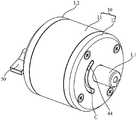
图1为本发明旋转模组一实施例的结构示意图;Fig. 1 is a schematic structural view of an embodiment of the rotary module of the present invention;
图2为图1所示实施例的旋转模组的部分结构示意图;Fig. 2 is a partial structural schematic diagram of the rotary module of the embodiment shown in Fig. 1;
图3为图1所示实施例的旋转模组的部分剖切结构图;Fig. 3 is a partial cut-away structure diagram of the rotary module of the embodiment shown in Fig. 1;
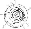
图4为图1所示实施例的旋转模组的部分结构示意图;Fig. 4 is a partial structural schematic diagram of the rotary module of the embodiment shown in Fig. 1;
图5为图1所示实施例的旋转模组的爆炸图;Fig. 5 is an exploded view of the rotary module of the embodiment shown in Fig. 1;
图6为图5中的环形保持架的部分结构示意图;Fig. 6 is a partial structural schematic diagram of the annular cage in Fig. 5;
图7为图5中的转轴的结构示意图。FIG. 7 is a schematic structural diagram of the rotating shaft in FIG. 5 .
具体实施方式detailed description
下面将结合本发明实施例中的附图,对本发明实施例中的技术方案进行清楚、完整地描述,显然,所描述的实施例仅仅是本发明的一部分实施例,而不是全部的实施例。基于本发明中的实施例,本领域普通技术人员在没有作出创造性劳动前提下所获得的所有其他实施例,都属于本发明保护的范围。The following will clearly and completely describe the technical solutions in the embodiments of the present invention with reference to the accompanying drawings in the embodiments of the present invention. Obviously, the described embodiments are only part of the embodiments of the present invention, not all of them. Based on the embodiments of the present invention, all other embodiments obtained by persons of ordinary skill in the art without creative efforts fall within the protection scope of the present invention.
需要说明,本发明实施例中所有方向性指示(诸如上、下、左、右、前、后……)仅用于解释在某一特定姿态(如附图所示)下各部件之间的相对位置关系、运动情况等,如果该特定姿态发生改变时,则该方向性指示也相应地随之改变。It should be noted that all directional indications (such as up, down, left, right, front, back...) in the embodiments of the present invention are only used to explain the relationship between the components in a certain posture (as shown in the accompanying drawings). Relative positional relationship, movement conditions, etc., if the specific posture changes, the directional indication will also change accordingly.
还需要说明的是,当元件被称为“固定于”或“设置于”另一个元件上时,它可以直接在另一个元件上或者可能同时存在居中元件。当一个元件被称为是“连接”另一个元件,它可以是直接连接另一个元件或者可能同时存在居中元件。It should also be noted that when an element is referred to as being “fixed” or “disposed on” another element, it can be directly on the other element or intervening elements may also exist. When an element is referred to as being "connected to" another element, it can be directly connected to the other element or intervening elements may also be present.
另外,在本发明中涉及“第一”、“第二”等的描述仅用于描述目的,而不能理解为指示或暗示其相对重要性或者隐含指明所指示的技术特征的数量。由此,限定有“第一”、“第二”的特征可以明示或者隐含地包括至少一个该特征。另外,各个实施例之间的技术方案可以相互结合,但是必须是以本领域普通技术人员能够实现为基础,当技术方案的结合出现相互矛盾或无法实现时应当认为这种技术方案的结合不存在,也不在本发明要求的保护范围之内。In addition, the descriptions involving "first", "second" and so on in the present invention are only for descriptive purposes, and should not be understood as indicating or implying their relative importance or implicitly indicating the quantity of the indicated technical features. Thus, the features defined as "first" and "second" may explicitly or implicitly include at least one of these features. In addition, the technical solutions of the various embodiments can be combined with each other, but it must be based on the realization of those skilled in the art. When the combination of technical solutions is contradictory or cannot be realized, it should be considered that the combination of technical solutions does not exist , nor within the scope of protection required by the present invention.
本发明提出一种旋转模组,可应用于摄影件(例如,魔术转接头、快拆板、手柄、三脚架和上手提等),作为摄影件的旋转关节;安装有该旋转模组的摄影器材,可与另一摄影件通过旋转模组转动相连,将其中一摄影件与摄影设备相连,即可以快速方便对摄影设备进行转动调节和锁定。The present invention proposes a rotary module, which can be applied to photographic pieces (such as magic adapters, quick release plates, handles, tripods, and upper handles, etc.), as the rotary joints of photographic pieces; photographic equipment equipped with the rotary module , can be rotated and connected with another photographic piece through the rotating module, and one of the photographic pieces is connected with the photographic equipment, that is, the rotational adjustment and locking of the photographic equipment can be performed quickly and conveniently.
参照图1至图5,在本实施例中,该旋转模组包括外壳10、转轴20、传动组件(未标号)和两个环形保持架40,其中:1 to 5, in this embodiment, the rotary module includes a
外壳10设有安装孔(未标号);The
两个环形保持架40沿安装孔的轴向依次转动设于安装孔内,两环形保持架40内具有轴向通孔,转轴20穿插于两环形保持架40中,即插在两环形保持架40的轴向通孔中;Two
两环形保持架40经传动组件传动配合,传动组件用于在一环形保持架40转动时,带动另一环形保持架40向相反方向转动,即两环形保持架40是联动的;The two
环形保持架40设有沿其周向分布的多个安装槽41,转轴20在对应两个环形保持架40的外周壁均设有凸起的抵接部21,安装槽41中设有滚动件41,一环形保持架40对应的抵接部21的凸起高度均沿转轴20的第一周向(例如,顺时针方向或逆时针方向)逐渐增大,另一环形保持架40对应的抵接部21的凸起高度均沿转轴20的第一周向逐渐减小,滚动件41设置在抵接部21与安装孔内壁之间。The
本实施例的旋转模组的工作原理为:1、在需要锁定旋转模组时,通过相对外壳10朝第一方向(例如,顺时针方向或逆时针方向)转动一个环形保持架40(为方便理解和后续描述,记为第一环形保持架40),第一环形保持架40朝第一方向的转动经传动组件带动另一环形保持架40(记为第二环形保持架40),相对外壳10朝第一方向的反方向(记为第二方向)转动,使两个环形保持架40的滚动件41移动到抵接部21凸起较高的一端与安装孔内壁之间,滚动件41的两侧分别抵紧抵接部21和安装孔内壁,如此,滚动件41与抵接部21之间的摩擦力增大,滚动件41与安装孔内壁之间的摩擦力也增大,使转轴20通过滚动件41与外壳10实现锁定;并且,由于两个环形保持架40对应的抵接部21的凸起高度增大方向相反,因此,当滚动件41抵紧在抵接部21和安装孔内壁之间时,无论是顺时针还是逆转动转轴20或外壳10,都会使其中一个环形保持架40的滚动件41分别与抵接部21和外壳10抵紧的更紧,可以保证锁定状态稳定可靠。2、在需要解锁旋转模组时,通过相对外壳10朝第二方向转动第一环形保持架40,在传动组件的传动作用下,第二环形安装架则相对外壳10朝第一方向转动,使两个环形保持架40的滚动件41从抵接部21凸起较高的一端与安装孔内壁之间,移动至抵接部21凸起较低的一端与安装孔内壁之间,滚动件41不在抵紧抵接部21和安装孔内壁,滚动件41的两侧分别抵紧抵接部21和安装孔内壁,如此,滚动件41与安装孔内壁及抵接部21之间的摩擦力大幅降低,滚动件41可相对外壳10和抵接部21自由转动,实现转轴20与外壳10之间的解锁。The working principle of the rotary module of this embodiment is: 1. When the rotary module needs to be locked, rotate an annular cage 40 in a first direction (for example, clockwise or counterclockwise) relative to the housing 10 (for convenience) Understanding and follow-up description, denoted as the first annular cage 40), the rotation of the first annular cage 40 in the first direction drives another annular cage 40 (denoted as the second annular cage 40) through the transmission assembly, and the opposite shell 10 rotates in the opposite direction of the first direction (referred to as the second direction), so that the rolling elements 41 of the two annular cages 40 move between the higher end of the abutting portion 21 and the inner wall of the mounting hole, and the rolling elements 41 The two sides of the two sides are respectively pressed against the abutting portion 21 and the inner wall of the mounting hole, so that the friction force between the rolling element 41 and the abutting portion 21 increases, and the friction force between the rolling element 41 and the inner wall of the mounting hole also increases, so that the rotating shaft 20 is locked with the housing 10 through the rolling element 41; and, since the protrusion heights of the abutting portions 21 corresponding to the two annular cages 40 increase in opposite directions, when the rolling element 41 is pressed against the abutting portion 21 and installed Between the inner walls of the hole, no matter whether the rotating shaft 20 or the housing 10 is rotated clockwise or reversely, the rolling element 41 of one of the annular cages 40 will be pressed against the abutting portion 21 and the housing 10 more tightly, which can ensure the locked state Stable and reliable. 2. When it is necessary to unlock the rotary module, by rotating the first
本实施例的旋转模组在摄影件上使用时,外壳10与一个摄影件连接,转轴20则与另一个摄影件连接,这样,两个摄影件就可以通过将旋转模组调至解锁状态时,以转动调节两个摄影件之间的角度,以及通过将旋转模组调至锁定状态,以将两个摄影件锁定在当前角度。When the rotary module of this embodiment is used on a photographic piece, the
本实施例的旋转模组,采用在外壳10的安装孔中转动设置两个环形保持架40,在环形保持架40中插设转轴20,环形保持架40周向设置安装有滚动件41的安装槽41,转轴20外壁设置与滚动件41对应的抵接部21,两个环形保持架40对应的抵接部21的凸起高度的增大方向相反,并且两环形保持架40经传动组件传动配合;如此,通过转动一个环形保持架40,带动另一个环形保持架40异向转动,使滚动件41移动至抵紧在抵接部21与安装孔内壁之间,即可实现旋转模组的锁定;以及通过转动一个环形保持架40,带动另一个环形保持架40异向转动,使滚动件41移动至与抵接部21和安装孔内壁的脱离抵紧状态,即可实现旋转模组的解锁。因此,本实施例的旋转模组应用作为摄像件之间的连接件时,可使摄像件之间快速进行角度调节和角度锁定,更加方便用户快速调节所需的拍摄角度。In the rotary module of this embodiment, two
参阅图3-5和图7,在一些实施例中,转轴20的外周壁对应每一环形保持架40还分别设有环形凸起22,环形凸起22与转轴20同轴,环形凸起22的高度大于抵接部21的最大凸起高度,滚动件41包括至少两个滚动体421,每一滚动件41的至少两个滚动体421分别卡在对应的环形凸起22的轴向上的两侧。3-5 and FIG. 7, in some embodiments, the outer peripheral wall of the
本实施例的旋转模组,通过各个滚动件41的至少两个滚动体421分别卡在环形凸起22的轴向两侧,使环形凸起22不能沿轴向上移动,如此保证了旋转模组在使用时,转轴20不会在相对环形安装架产生轴向晃动,即不会相对与外壳10产生轴向晃动,如此,保证了通过旋转模组相连的两个摄影件之间的稳定性。In the rotary module set of this embodiment, at least two
在一些实施例中,至少部分安装槽41中设有至少一个分隔部(图中未示),至少一个分隔部将其分隔成沿环形保持架40轴向排布的至少两个槽段;滚动件41的至少两个滚动体421分别安装在至少两个槽段中,滚动件41通过采用多个滚动体421分别安装在安装槽41的各个槽段中,使得滚动体421与抵接部21和外壳10内壁之间的抵接配合更加稳定可靠,使得锁定状态更加牢固、稳定。In some embodiments, at least one partition (not shown) is provided in at least part of the
在本实施例图中,滚动件41以两个滚珠为例,在其他实施例中,滚动件41也可以为一个或更多个滚珠,滚动件41还可为轴心与转轴20的轴心平行的至少一个圆柱、圆轮或圆盘等可转动的结构件。In the figure of this embodiment, two balls are used as an example for the rolling
在一些实施例中,安装孔的孔壁和/或抵接部21上设有适配滚珠的滚道(图中未示),例如,滚道可为安装孔的孔壁和/抵接部21形成的环形导向槽,环形导向槽可为安装孔的孔壁和/抵接部21上凹设形成或在凸设的两环形凸棱之间形成,环形导向槽与转轴20同轴,滚珠一部分卡在环形导向槽内。本实例通过增加设置与滚珠适配的滚道,如此,增强了滚珠、转轴20、环形保持架40以及外壳10之间在轴向上的稳定性,避免转轴20相对外壳10或环形保持架40产生轴向移动,保证了在锁定状态下,旋转组件连接的两摄像件之间的稳定性。当然,在其他实施例中,滚道还可为其他能够实现相同功能作用的结构。In some embodiments, the hole wall and/or the abutting
参阅图3、图4和图6,在一些实施例中,外壳10的两端分别设有与安装孔同轴的限位台阶(未标号),两环形保持架40相互远离的一端均设有环形卡边43,两环形保持架40的环形卡边43分别适配卡在外壳10两端的限位台阶中。本实施例通过在外壳10的两端分别设置限位台阶,且在环形保持架40的外端设置与限位台阶适配的环形卡边43,如此,环形保持架40在与外壳10进行安装时,只需将环形保持架40的内端从安装孔的一端插入,并使环形卡边43卡在限位台阶,即可实现环形保持架40的快速定位安装,既提升了环形保持架40的安装速度,又保证了环形保持架40的安装精度。Referring to Fig. 3, Fig. 4 and Fig. 6, in some embodiments, the two ends of the
在一些实施例中,至少一环形保持架40靠近安装孔端口的一端设有手持部50。通过设置手持部50,更方便用户对环形保持架40进行转动解锁操作。本实施例图中,手持部50以包括一扳扣为例,通过掰动扳扣带着环形保持架40进行转动;当然,在其他实施例中,手持部50还可为其它结构。In some embodiments, at least one
参阅图2和图4,在一些实施例中,旋转模组还包括弹簧件60,弹簧件60位于转轴20的一侧,弹簧件60的一端连接环形保持架40,另一端连接外壳10,弹簧件60驱动滚动件41抵接抵接部21以及外壳10,以使得转轴20与外壳10锁定。也就是,弹簧件60通过弹性作用于环形保持架40和外壳10,使环形保持架40上的滚动件41保持向抵接部21凸起较高的一端移动的趋势,从而滚动件41保持抵紧抵接部21和安装孔内壁,转轴20与外壳10保持锁定状态。在解锁时,通过外力驱动环形保持架40向解锁的方向转动,使滚动件41向抵接部21凸起较低的一端移动,从而滚动件41保持脱离与抵接部21和安装孔内壁的抵紧状态,完成解锁。在外力撤去后,环形保持架40会自动在弹簧件60的弹性作用力下,向锁定的方向转动,从而是转轴20与外壳10恢复锁定状态。Referring to Fig. 2 and Fig. 4, in some embodiments, the rotary module further includes a
本实施例通过外壳10与环形保持架40之间增加弹簧件60相连,使得旋转模组可以更加稳定可靠的保持在锁定状态,提升了旋转模组锁定状态的可靠性。In this embodiment, a
参阅图3至图5,在一些实施例中,传动组件包括传动锥齿轮31,传动锥齿轮31位于两环形保持架40之间,两环形保持架40相互靠近的一端均设有锥齿轮面S,传动锥齿轮31转动安装于转轴20的外周壁上,传动锥齿轮31与两环形保持架40的锥齿轮面S均啮合。具体的,在转动任一个环形保持架40时,该环形保持架40的锥齿轮面S会驱动传动锥齿轮31转动,进而传动锥齿轮31则驱动另一环形保持架40的锥齿轮面S驱动另一环形保持架40转动。本实施例的传动组件通过采用一个传动锥齿轮31和与其啮合的两个锥齿轮面S的方案,不仅传动稳定可靠,而且结构简单,使旋转模组的整体结构可以更加小巧,可安装在摄影器材中的各种狭小空间中,通用性强,并且小巧的尺寸实现隐藏式安装,可不裸露在摄影器材的外部,使摄影器材保证整体的外观简洁。3 to 5, in some embodiments, the transmission assembly includes a
需要说明的是,在其他实施例中,传动组件还可以为其它齿轮传动方式的组合结构或其它传动方式的传动结构方案。It should be noted that, in other embodiments, the transmission assembly may also be a combined structure of other gear transmission modes or a transmission structure scheme of other transmission modes.
进一步地,本实施例在安装孔的内壁还设有环形避让槽111,环形避让槽111与传动锥齿轮31位置正对。传动锥齿轮31是转动设置在转轴20的外周壁上,因此传动锥齿轮31会跟着转轴20一起转动,为了保证外壳10不对传动锥齿轮31的转动造成干涉影响,因此在安装孔的内壁设置环形避让槽111,对传动锥齿轮31进行避位。Further, in this embodiment, an
参阅图1至图3以及图5,在一些实施例中,外壳10包括含有安装孔的桶体11和盖体12,桶体11的一端敞口设置;盖体12盖设于桶体11的敞口端,盖体12设有避让孔,转轴20具有从避让孔伸出外壳10的第一连接部L1,第一连接部L1用于连接第一摄影件;桶体11远离盖体12的一端设有第二连接部L2,第二连接部L2用于连接第二摄影件。本实施例的旋转模组在使用时,第一连接部L1与一摄影件连接,第二连接部L2与另一摄影件连接,这样,两个摄影件就可以通过将旋转模组调至解锁状态时,以转动调节两个摄影件之间的角度,以及通过将旋转模组调至锁定状态,以将两个摄影件锁定在当前角度。当然,在其他实施例中,第二连接部L2还可以设置在桶体11的外壁的任一位置。Referring to Figures 1 to 3 and Figure 5, in some embodiments, the
进一步地,盖体12和桶体11远离盖体12的一端上均设有绕转轴20轴心设置的弧形导槽C,两环形保持架40对应弧形导槽C的一端设有卡于弧形导槽C中的滑块44,如此,手持部50可连接于任一滑块44,从而通过手持部50驱动滑块沿弧形导槽滑动C,以驱动环形保持架40转动进行解锁。并且弧形导槽C和滑块44的配合,使得环形保持架40的转动更加顺畅。Further, the end of the
当然,在其他实施例中,桶体11还可以为两端均敞口设置,两端可分别通过一盖体12进行封盖。Of course, in other embodiments, both ends of the
在一些实施例中,抵接部21到转轴20轴心的最大距离与最小距离的差值为L,L即为抵接部21朝安装孔内壁推动滚动组件移动的距离范围,其中L为0.3~1.5mm,例如L为0.5、0.7、0.9、1、1.2、1.3mm。In some embodiments, the difference between the maximum distance and the minimum distance from the abutting
在一些实施例中,滚动件41的半径可为0.3~20mm,例如,滚动件41的半径为1mm、2mm、3mm、4mm、5mm、6mm、8mm、10mm、13mm、15mm、18mm、20mm。In some embodiments, the radius of the rolling
在一些实施例中,L与滚动组件的半径的比值为0.1~0.6,例如0.5、0.4、0.3。In some embodiments, the ratio of L to the radius of the rolling assembly is 0.1-0.6, such as 0.5, 0.4, 0.3.
在一些实施例中,抵接部21到转轴20轴心的最大距离与最小距离的差值为L,安装孔的直径为R,L与R的比值为0.012~0.05,例如0.01、0.015、0.025、0.03、0.04、0.045。In some embodiments, the difference between the maximum distance and the minimum distance from the
旋转组件通过采用上述实施例中的尺寸数据,可以保证旋转组件的转动调节和锁定状态都非常稳定可靠。By adopting the dimensional data in the above-mentioned embodiments, the rotation assembly can ensure that the rotation adjustment and locking state of the rotation assembly are very stable and reliable.
本发明进一步提出一种摄影设备,该摄影配件包括旋转模组、第一摄影件和第二摄影件,该旋转模组的具体结构参照上述实施例,由于本摄影设备采用了上述旋转模组所有实施例的全部技术方案,因此至少具有上述实施例的技术方案所带来的所有有益效果,在此不再一一赘述。其中,第一摄影件与旋转模组的转轴20连接,第二摄影件与旋转模组的外壳10连接;第一摄影件和第二摄影件其中之一可与摄影设备(照相机或摄像机)相连。The present invention further proposes a photographic device. The photographic accessories include a rotating module, a first photographing piece and a second photographing piece. The specific structure of the rotating module refers to the above-mentioned embodiment. All the technical solutions of the embodiments at least have all the beneficial effects brought about by the technical solutions of the above embodiments, and will not be repeated here. Wherein, the first photographing piece is connected with the rotating
以上所述的仅为本发明的部分或优选实施例,无论是文字还是附图都不能因此限制本发明保护的范围,凡是在与本发明一个整体的构思下,利用本发明说明书及附图内容所作的等效结构变换,或直接/间接运用在其他相关的技术领域均包括在本发明保护的范围内。What is described above is only a part or preferred embodiment of the present invention, neither words nor accompanying drawings can limit the scope of protection of the present invention. The equivalent structural transformations made, or direct/indirect applications in other related technical fields are all included in the protection scope of the present invention.
Claims (12)
Translated fromChinesePriority Applications (3)
| Application Number | Priority Date | Filing Date | Title |
|---|---|---|---|
| CN202211091332.6ACN115451281A (en) | 2022-09-07 | 2022-09-07 | Rotary modules and photography equipment |
| US18/462,381US20240077170A1 (en) | 2022-09-07 | 2023-09-06 | Composite bearing, rotating assembly, and photographic assembly |
| EP23195803.4AEP4338882A1 (en) | 2022-09-07 | 2023-09-06 | Composite bearing, rotating assembly, and photographic assembly |
Applications Claiming Priority (1)
| Application Number | Priority Date | Filing Date | Title |
|---|---|---|---|
| CN202211091332.6ACN115451281A (en) | 2022-09-07 | 2022-09-07 | Rotary modules and photography equipment |
Publications (1)
| Publication Number | Publication Date |
|---|---|
| CN115451281Atrue CN115451281A (en) | 2022-12-09 |
Family
ID=84303184
Family Applications (1)
| Application Number | Title | Priority Date | Filing Date |
|---|---|---|---|
| CN202211091332.6APendingCN115451281A (en) | 2022-09-07 | 2022-09-07 | Rotary modules and photography equipment |
Country Status (1)
| Country | Link |
|---|---|
| CN (1) | CN115451281A (en) |
Citations (10)
| Publication number | Priority date | Publication date | Assignee | Title |
|---|---|---|---|---|
| US5388942A (en)* | 1992-02-28 | 1995-02-14 | Black & Decker Inc. | Flange locks |
| JP2010106950A (en)* | 2008-10-30 | 2010-05-13 | Ntn Corp | Reverse input preventing clutch |
| US20200078925A1 (en)* | 2018-09-06 | 2020-03-12 | Xiamen Nanchbit Precision Tools Co., Ltd. | Stepless telescoping mechanism and stepless telescopic screwdriver |
| CN210856777U (en)* | 2019-08-20 | 2020-06-26 | 临安市万利纸业有限公司 | Filter sieve |
| CN211089755U (en)* | 2020-02-28 | 2020-07-24 | 深圳市乐其网络科技有限公司 | Quick detach connecting piece and shooting equipment |
| CN111927849A (en)* | 2020-08-31 | 2020-11-13 | 北京交跃通达检测科技有限公司 | Quick connecting mechanism and tunnel inspection system |
| CN112145942A (en)* | 2020-10-22 | 2020-12-29 | 深圳市清友智能创新有限公司 | Shooting aids |
| CN112292926A (en)* | 2020-11-10 | 2021-02-02 | 安徽省阜阳市盛大机械有限公司 | Rotary cultivator |
| CN112808919A (en)* | 2021-02-04 | 2021-05-18 | 中铁宝桥集团有限公司 | Quick connection and disassembly method and quick connection device |
| CN218178456U (en)* | 2022-09-07 | 2022-12-30 | 深圳市乐其网络科技有限公司 | Rotary module and camera module |
- 2022
- 2022-09-07CNCN202211091332.6Apatent/CN115451281A/enactivePending
Patent Citations (10)
| Publication number | Priority date | Publication date | Assignee | Title |
|---|---|---|---|---|
| US5388942A (en)* | 1992-02-28 | 1995-02-14 | Black & Decker Inc. | Flange locks |
| JP2010106950A (en)* | 2008-10-30 | 2010-05-13 | Ntn Corp | Reverse input preventing clutch |
| US20200078925A1 (en)* | 2018-09-06 | 2020-03-12 | Xiamen Nanchbit Precision Tools Co., Ltd. | Stepless telescoping mechanism and stepless telescopic screwdriver |
| CN210856777U (en)* | 2019-08-20 | 2020-06-26 | 临安市万利纸业有限公司 | Filter sieve |
| CN211089755U (en)* | 2020-02-28 | 2020-07-24 | 深圳市乐其网络科技有限公司 | Quick detach connecting piece and shooting equipment |
| CN111927849A (en)* | 2020-08-31 | 2020-11-13 | 北京交跃通达检测科技有限公司 | Quick connecting mechanism and tunnel inspection system |
| CN112145942A (en)* | 2020-10-22 | 2020-12-29 | 深圳市清友智能创新有限公司 | Shooting aids |
| CN112292926A (en)* | 2020-11-10 | 2021-02-02 | 安徽省阜阳市盛大机械有限公司 | Rotary cultivator |
| CN112808919A (en)* | 2021-02-04 | 2021-05-18 | 中铁宝桥集团有限公司 | Quick connection and disassembly method and quick connection device |
| CN218178456U (en)* | 2022-09-07 | 2022-12-30 | 深圳市乐其网络科技有限公司 | Rotary module and camera module |
Non-Patent Citations (1)
| Title |
|---|
| 马振平等: "滚珠旋压成形技术", vol. 1, 30 September 2011, 冶金工业出版社, pages: 29* |
Similar Documents
| Publication | Publication Date | Title |
|---|---|---|
| US11104452B2 (en) | Gimbal, imaging device and unmanned aerial vehicle | |
| CN113950596B (en) | Quick release connection components, handheld gimbal and shooting equipment | |
| US7670072B2 (en) | Cam-locking positioning mechanism | |
| US20080210832A1 (en) | Support For Video/Photographic Equipment | |
| CN214890112U (en) | Locking mechanical system, cloud platform and camera equipment | |
| US20250164864A1 (en) | Foldable mounting device and method of operating the same | |
| JP7005730B2 (en) | Filter mounting structure | |
| US11906101B2 (en) | Photographic equipment assembly and quick connection assembly thereof | |
| WO2017080337A1 (en) | Photographic extension bar and shooting device | |
| WO2019114386A1 (en) | Camera structure and pan-tilt thereof | |
| CN218178456U (en) | Rotary module and camera module | |
| CN110195745B (en) | Transmission structure, follow burnt ware execution end and image device | |
| CN115451281A (en) | Rotary modules and photography equipment | |
| WO2018192085A1 (en) | Tripod head structure | |
| US6639731B1 (en) | Zoom lens barrel assembly of camera | |
| CN218543715U (en) | Rotating structure and shooting auxiliary device with same | |
| CN215891791U (en) | Locking mechanism, cloud platform and supplementary shooting equipment | |
| CN217422758U (en) | Universal strange hand support | |
| CN116518223A (en) | Tripod stand | |
| CN211203395U (en) | Switching subassembly, cloud platform subassembly and mount subassembly | |
| CN215636138U (en) | Hand-held cloud platform | |
| JP2003066314A (en) | Click stop mechanism between two mating members | |
| US8204368B2 (en) | Lens port | |
| CN218720167U (en) | Rotary Modules and Camera Components | |
| CN220186259U (en) | Rotation locking limiting device |
Legal Events
| Date | Code | Title | Description |
|---|---|---|---|
| PB01 | Publication | ||
| PB01 | Publication | ||
| SE01 | Entry into force of request for substantive examination | ||
| SE01 | Entry into force of request for substantive examination | ||
| CB02 | Change of applicant information | Country or region after:China Address after:Room 103, 501, 601, Building 5, Fenghe Industrial Park, No. 1301-50, Sightseeing Road, Xinlan Community, Guanlan Street, Longhua District, Shenzhen, Guangdong 518000 Applicant after:Shenzhen Leqi Innovation Co.,Ltd. Address before:Room 103, 501, 601, Building 5, Fenghe Industrial Park, No. 1301-50, Sightseeing Road, Xinlan Community, Guanlan Street, Longhua District, Shenzhen, Guangdong 518000 Applicant before:SHENZHEN LEQI NETWORK TECHNOLOGY Co.,Ltd. Country or region before:China | |
| CB02 | Change of applicant information | ||
| CB02 | Change of applicant information | Country or region after:China Address after:No. 58 Ping'an Road, Dafu Community, Guanlan Street, Longhua District, Shenzhen City, Guangdong Province 518000, China Applicant after:Shenzhen Leqi Innovation Co.,Ltd. Address before:Room 103, 501, 601, Building 5, Fenghe Industrial Park, No. 1301-50, Sightseeing Road, Xinlan Community, Guanlan Street, Longhua District, Shenzhen, Guangdong 518000 Applicant before:Shenzhen Leqi Innovation Co.,Ltd. Country or region before:China | |
| CB02 | Change of applicant information |