CN115451033A - Clutch cover assembly - Google Patents
Clutch cover assemblyDownload PDFInfo
- Publication number
- CN115451033A CN115451033ACN202211224150.1ACN202211224150ACN115451033ACN 115451033 ACN115451033 ACN 115451033ACN 202211224150 ACN202211224150 ACN 202211224150ACN 115451033 ACN115451033 ACN 115451033A
- Authority
- CN
- China
- Prior art keywords
- clutch cover
- diaphragm spring
- positioning
- cover body
- wall surface
- Prior art date
- Legal status (The legal status is an assumption and is not a legal conclusion. Google has not performed a legal analysis and makes no representation as to the accuracy of the status listed.)
- Pending
Links
Images


Classifications
- F—MECHANICAL ENGINEERING; LIGHTING; HEATING; WEAPONS; BLASTING
- F16—ENGINEERING ELEMENTS AND UNITS; GENERAL MEASURES FOR PRODUCING AND MAINTAINING EFFECTIVE FUNCTIONING OF MACHINES OR INSTALLATIONS; THERMAL INSULATION IN GENERAL
- F16D—COUPLINGS FOR TRANSMITTING ROTATION; CLUTCHES; BRAKES
- F16D13/00—Friction clutches
- F16D13/58—Details
- F16D13/70—Pressure members, e.g. pressure plates, for clutch-plates or lamellae; Guiding arrangements for pressure members
- F—MECHANICAL ENGINEERING; LIGHTING; HEATING; WEAPONS; BLASTING
- F16—ENGINEERING ELEMENTS AND UNITS; GENERAL MEASURES FOR PRODUCING AND MAINTAINING EFFECTIVE FUNCTIONING OF MACHINES OR INSTALLATIONS; THERMAL INSULATION IN GENERAL
- F16D—COUPLINGS FOR TRANSMITTING ROTATION; CLUTCHES; BRAKES
- F16D13/00—Friction clutches
- F16D13/58—Details
- F16D13/72—Features relating to cooling
Landscapes
- Engineering & Computer Science (AREA)
- General Engineering & Computer Science (AREA)
- Mechanical Engineering (AREA)
- Mechanical Operated Clutches (AREA)
Abstract
Description
Translated fromChinese技术领域technical field
本发明涉及离合器技术领域,具体涉及一种离合器盖总成。The invention relates to the technical field of clutches, in particular to a clutch cover assembly.
背景技术Background technique
在离合器从分离到接合的过程中,摩擦片与飞轮和压盘之间要发生摩擦,产生大量热量,这些热量需要及时散出,以避免摩擦片因温度过高而损坏。由于需要保证自身强度以避免受力变形,现有的离合器盖如中国授权公告号CN210484452U,一种散热良好的离合器盖板公开的技术方案:“离合器盖板本体的外壁上设置有安装孔,以使离合器盖板本体安装固定;所述离合器盖板本体与压盘接触的a端面上设置有第一散热孔以及b端面设置有第二散热孔;散热件,所述散热件设置在离合器盖板本体的中部位置,且位于第一散热孔与第二散热孔之间,所述散热件为硬性材质”。该技术方案公开的散热件为铜质材质,比较柔软,将铜质材质的散热件设置在离合器盖板本体的中部位置,结构设计不合理,会导致离合器盖板强度不好,容易受力变形;膜片弹簧无定位件,安装到离合器盖内后会导致膜片弹簧定位不可靠,实用性差。In the process of the clutch from separation to engagement, friction occurs between the friction plate, the flywheel and the pressure plate, and a large amount of heat is generated, which needs to be dissipated in time to avoid damage to the friction plate due to excessive temperature. Due to the need to ensure its own strength to avoid stress deformation, the existing clutch cover, such as the Chinese Authorized Notice No. CN210484452U, a disclosed technical solution of a clutch cover with good heat dissipation: "The outer wall of the clutch cover body is provided with mounting holes to The clutch cover plate body is installed and fixed; the a end surface of the clutch cover plate body in contact with the pressure plate is provided with a first heat dissipation hole and the b end surface is provided with a second heat dissipation hole; the heat dissipation part is arranged on the clutch cover plate The middle position of the body, and between the first heat dissipation hole and the second heat dissipation hole, the heat dissipation element is made of hard material". The heat sink disclosed in this technical solution is made of copper, which is relatively soft. If the copper heat sink is placed in the middle of the clutch cover body, the structural design is unreasonable, which will lead to poor strength of the clutch cover and easy deformation under force. ; Diaphragm spring has no locating parts, after being installed in the clutch cover, it will lead to unreliable positioning of diaphragm spring and poor practicability.
发明内容Contents of the invention
针对现有技术存在的不足,本发明的目的在于提供一种结构设计合理、强度好、散热性能好、对膜片弹簧定位可靠且实用性好的离合器盖总成。In view of the deficiencies in the prior art, the object of the present invention is to provide a clutch cover assembly with reasonable structural design, good strength, good heat dissipation performance, reliable positioning of the diaphragm spring and good practicability.
为实现上述目的,本发明提供了如下技术方案:一种离合器盖总成,包括离合器盖本体,所述离合器盖本体内设置有一个置物凹槽,所述置物凹槽内设置有膜片弹簧,所述离合器盖本体的上端面中部设置有一个圆形盖体通孔,所述圆形盖体通孔的内壁面上固定设置有一个散热圈,所述散热圈的内壁面上一体设置有若干片散热片;In order to achieve the above object, the present invention provides the following technical solutions: a clutch cover assembly, including a clutch cover body, a storage groove is arranged in the clutch cover body, a diaphragm spring is arranged in the storage groove, The middle part of the upper end surface of the clutch cover body is provided with a circular cover body through hole, and a heat dissipation ring is fixedly arranged on the inner wall surface of the circular cover body through hole, and a plurality of holes are integrally arranged on the inner wall surface of the heat dissipation ring sheet heat sink;
所述置物凹槽的内壁面上一体设置有若干个定位凸起,所述膜片弹簧对准每个定位凸起位置均设置有一个定位凹槽,所述定位凹槽的内壁面上固定设置有弹性耐磨层;The inner wall surface of the storage groove is integrally provided with several positioning protrusions, and the diaphragm spring is aligned with each positioning protrusion position to be provided with a positioning groove, and the inner wall surface of the positioning groove is fixedly arranged Elastic wear-resistant layer;
所述离合器盖本体的置物凹槽的内壁面上固定设置有碳纤维涂层;所述离合器盖本体的外表面上固定设置有镀铬加强层;The inner wall surface of the storage groove of the clutch cover body is fixedly provided with a carbon fiber coating; the outer surface of the clutch cover body is fixedly provided with a chrome-plated reinforcing layer;
所述膜片弹簧的下端设置有压盘,所述压盘的上端与膜片弹簧之间设置有若干个膜片弹簧定位件;The lower end of the diaphragm spring is provided with a pressure plate, and several diaphragm spring positioning parts are arranged between the upper end of the pressure plate and the diaphragm spring;
所述膜片弹簧的下端与压盘之间至少设置有一个支撑圈。At least one supporting ring is arranged between the lower end of the diaphragm spring and the pressure plate.
本发明进一步设置为:所述膜片弹簧的边缘处设置有若干个定位通孔,所述膜片弹簧定位件包括螺栓,所述压盘的上端面对准每个定位通孔位置设置有一个螺栓连接孔,所述每个定位件下端穿过对准的定位通孔后与对准的螺栓连接孔螺纹连接。The present invention is further set as follows: the edge of the diaphragm spring is provided with several positioning through holes, the diaphragm spring positioning member includes bolts, and the upper end surface of the pressure plate is provided with a Bolt connection holes, the lower end of each positioning member passes through the aligned positioning through holes and is threadedly connected with the aligned bolt connection holes.
本发明还进一步设置为:所述膜片弹簧的中部一体设置有多片弹簧片,每片弹簧片的上端面局部位置固定设置有耐磨树脂涂层。The present invention is further configured as follows: the middle part of the diaphragm spring is integrally provided with a plurality of spring sheets, and the upper end surface of each spring sheet is fixedly provided with a wear-resistant resin coating at a local position.
本发明还进一步设置为:所述弹性耐磨层为硅橡胶层,且弹性耐磨层的厚度为0.5—1.5mm。In the present invention, it is further set that: the elastic wear-resistant layer is a silicon rubber layer, and the thickness of the elastic wear-resistant layer is 0.5-1.5mm.
本发明还进一步设置为:所述碳纤维涂层由长丝碳纤维制成,且碳纤维涂层的厚度为0.1—0.5mm。The present invention is further provided that: the carbon fiber coating is made of filament carbon fiber, and the thickness of the carbon fiber coating is 0.1-0.5 mm.
本发明还进一步设置为:所述镀铬加强层的厚度为1-300μm。In the present invention, it is further set that: the thickness of the chrome plating strengthening layer is 1-300 μm.
本发明的优点是:本发明结构设置合理,散热圈设置在圆形盖体通孔的内壁面上,且散热圈的内壁面上一体设置有若干片散热片,结构设计合理,不但散热性能好,且对离合器盖本体的中部起到加强作用;碳纤维涂层对离合器盖本体的内部起到加强作用,镀铬加强层对离合器盖本体的外部起到加强作用,使得离合器盖本体的强度好,不易变形;膜片弹簧通过定位凹槽与定位凸起定位,在工作时,膜片弹簧定位可靠,当膜片弹簧的弹簧片上端面中部受压时,定位凸起和支撑圈起到定位作用,使得膜片弹簧边缘通过膜片弹簧定位件带动压盘翘起,实用性好。The advantages of the present invention are: the structure of the present invention is reasonably arranged, the heat dissipation ring is arranged on the inner wall surface of the through hole of the circular cover, and the inner wall surface of the heat dissipation ring is integrally provided with several heat sinks, the structural design is reasonable, and the heat dissipation performance is good. , and strengthen the middle part of the clutch cover body; the carbon fiber coating strengthens the inside of the clutch cover body, and the chrome-plated reinforcement layer strengthens the outside of the clutch cover body, making the clutch cover body strong and not easy Deformation; the diaphragm spring is positioned by the positioning groove and the positioning protrusion. When it is working, the diaphragm spring is positioned reliably. The edge of the diaphragm spring drives the pressure plate to tilt through the diaphragm spring positioning part, which has good practicability.
下面结合说明书附图和具体实施例对本发明作进一步说明。The present invention will be further described below in conjunction with the accompanying drawings and specific embodiments.
附图说明Description of drawings
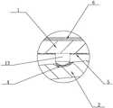
图1为本发明实施例的结构示意图;Fig. 1 is the structural representation of the embodiment of the present invention;
图2为图1中I部的放大示意图;Fig. 2 is the enlarged schematic diagram of part I in Fig. 1;
图3为图1中II部的放大示意图。FIG. 3 is an enlarged schematic view of part II in FIG. 1 .
具体实施方式detailed description
在本实施例的描述中,需要说明的是,如出现术语“中心”、“上”、“下”、“左”、“右”、“竖直”、“水平”、“内”、“外”、“前”、“后”等,其所指示的方位或位置关系为基于附图所示的方位或位置关系,仅是为了便于描述本发明和简化描述,而不是指示或暗示所指的装置或元件必须具有特定的方位、以特定的方位构造和操作,因此,不能理解为对本发明的限制。此外,如出现术语“第一”、“第二”、“第三”仅用于描述目的,而不能理解为指示或暗示相对重要性。In the description of this embodiment, it should be noted that if the terms "center", "upper", "lower", "left", "right", "vertical", "horizontal", "inner", " Outside", "front", "rear", etc., the orientation or positional relationship indicated is based on the orientation or positional relationship shown in the drawings, which is only for the convenience of describing the present invention and simplifying the description, rather than indicating or implying Any device or element must have a specific orientation, be constructed and operate in a specific orientation and, therefore, should not be construed as limiting the invention. In addition, the terms "first", "second", and "third" are used for descriptive purposes only, and should not be understood as indicating or implying relative importance.
参见图1、图2和图3,本发明公开的一种离合器盖总成,包括离合器盖本体1,所述离合器盖本体1内设置有一个置物凹槽11,所述置物凹槽11内设置有膜片弹簧2,所述离合器盖本体1的上端面中部设置有一个圆形盖体通孔12,所述圆形盖体通孔12的内壁面上固定设置有一个散热圈3,所述散热圈3的内壁面上一体设置有若干片散热片31;Referring to Fig. 1, Fig. 2 and Fig. 3, a clutch cover assembly disclosed by the present invention includes a
所述置物凹槽11的内壁面上一体设置有若干个定位凸起13,所述膜片弹簧2对准每个定位凸起位置均设置有一个定位凹槽21,所述定位凹槽21的内壁面上固定设置有弹性耐磨层4;The inner wall surface of the
所述离合器盖本体1的置物凹槽11的内壁面上固定设置有碳纤维涂层5;所述离合器盖本体1的外表面上固定设置有镀铬加强层6;The inner wall surface of the
所述膜片弹簧2的下端设置有压盘7,所述压盘7的上端与膜片弹簧2之间设置有若干个膜片弹簧定位件8;The lower end of the
所述膜片弹簧2的下端与压盘7之间至少设置有一个支撑圈9。At least one
作为优选的,所述散热圈3和散热片31均为铜材质,且散热片31的数量设置3片以上,散热片31呈环形状均匀分布;所述离合器盖本体1为不锈钢材质,所述散热圈3与圆形盖体通孔12的内壁面焊接固定;定位凸起13的数量设置3个以上,且定位凸起13呈环形状均匀分布;或定位凸起13可以采用定位凸环代替;所述定位凹槽21与定位凸起13的数量和结构均相匹配,当定位凸起底部为球形部,定位凹槽21为弧形凹槽时结构最佳;所述压盘7为不锈钢材质。所述支撑圈9为不锈钢材质或橡胶材质。Preferably, the
为使本发明结构设置更加合理,作为优选的,本实施例所述膜片弹簧2的边缘处设置有若干个定位通孔22,所述膜片弹簧定位件8包括螺栓,所述压盘7的上端面对准每个定位通孔位置设置有一个螺栓连接孔,所述每个定位件8下端穿过对准的定位通孔后与对准的螺栓连接孔螺纹连接。In order to make the structural setting of the present invention more reasonable, as a preference, several positioning through
所述膜片弹簧2的中部一体设置有多片弹簧片23,每片弹簧片23的上端面局部位置固定设置有耐磨树脂涂层10。作为优选的,耐磨树脂涂层10为PEEK树脂层,且耐磨树脂涂层10通过现有的免钉胶或粘合剂与对准的弹簧片23的上端面局部位置粘接固定后构成一体结构。The middle part of the
所述弹性耐磨层4为硅橡胶层,且弹性耐磨层4的厚度为0.5—1.5mm。The elastic wear-
所述碳纤维涂层5由长丝碳纤维制成,且碳纤维涂层5的厚度为0.1—0.5mm。作为优选的,所述碳纤维涂层5与置物凹槽11的内壁面通过现有的免钉胶或粘合剂粘接固定后构成一体结构。The
所述镀铬加强层6的厚度为1-300μm。The thickness of the chrome plating strengthening
实际应用时,散热圈设置在圆形盖体通孔的内壁面上,且散热圈的内壁面上一体设置有若干片散热片,结构设计合理,不但散热性能好,且对离合器盖本体的中部起到加强作用;碳纤维涂层对离合器盖本体的内部起到加强作用,镀铬加强层对离合器盖本体的外部起到加强作用,使得离合器盖本体的强度好,不易变形;膜片弹簧通过定位凹槽与定位凸起定位,在工作时,膜片弹簧定位可靠,当膜片弹簧的弹簧片上端面中部受压时,定位凸起和支撑圈起到定位作用,使得膜片弹簧边缘通过膜片弹簧定位件带动压盘翘起,实用性好。In actual application, the cooling ring is arranged on the inner wall of the through hole of the circular cover, and the inner wall of the cooling ring is integrally provided with several cooling fins. It plays a strengthening role; the carbon fiber coating strengthens the inside of the clutch cover body, and the chrome-plated reinforcement layer strengthens the outside of the clutch cover body, so that the clutch cover body has good strength and is not easy to deform; the diaphragm spring passes through the positioning concave The groove and the positioning protrusion are positioned. When working, the diaphragm spring is positioned reliably. When the middle part of the upper end face of the diaphragm spring is pressed, the positioning protrusion and the support ring play a positioning role, so that the edge of the diaphragm spring passes through the diaphragm spring. The positioning part drives the pressure plate to tilt up, which has good practicability.
上述实施例对本发明的具体描述,只用于对本发明进行进一步说明,不能理解为对本发明保护范围的限定,本领域的技术工程师根据上述发明的内容对本发明作出一些非本质的改进和调整均落入本发明的保护范围之内。The specific description of the present invention in the above-mentioned embodiments is only used to further illustrate the present invention, and can not be interpreted as limiting the protection scope of the present invention. Technical engineers in the field make some non-essential improvements and adjustments to the present invention according to the content of the above-mentioned invention. Into the protection scope of the present invention.
Claims (6)
Translated fromChinesePriority Applications (1)
| Application Number | Priority Date | Filing Date | Title |
|---|---|---|---|
| CN202211224150.1ACN115451033A (en) | 2022-10-08 | 2022-10-08 | Clutch cover assembly |
Applications Claiming Priority (1)
| Application Number | Priority Date | Filing Date | Title |
|---|---|---|---|
| CN202211224150.1ACN115451033A (en) | 2022-10-08 | 2022-10-08 | Clutch cover assembly |
Publications (1)
| Publication Number | Publication Date |
|---|---|
| CN115451033Atrue CN115451033A (en) | 2022-12-09 |
Family
ID=84309771
Family Applications (1)
| Application Number | Title | Priority Date | Filing Date |
|---|---|---|---|
| CN202211224150.1APendingCN115451033A (en) | 2022-10-08 | 2022-10-08 | Clutch cover assembly |
Country Status (1)
| Country | Link |
|---|---|
| CN (1) | CN115451033A (en) |
Citations (8)
| Publication number | Priority date | Publication date | Assignee | Title |
|---|---|---|---|---|
| JP2003220538A (en)* | 2002-01-29 | 2003-08-05 | Hamajima Kogyo Kk | Telescopic cover |
| CN106286627A (en)* | 2015-06-12 | 2017-01-04 | 襄阳楚安科技实业有限公司 | A kind of automobile clutch |
| CN205895956U (en)* | 2016-07-30 | 2017-01-18 | 重庆西查奇科技有限公司 | Take clutch cover assembly of fin |
| CN205895955U (en)* | 2016-07-30 | 2017-01-18 | 重庆西查奇科技有限公司 | Automobile diaphragm spring clutch cover assembly |
| CN208311302U (en)* | 2018-05-10 | 2019-01-01 | 苏州市润凯汽车配件制造有限公司 | A kind of clutch cover and plate assembly structure of rapid cooling |
| CN210949605U (en)* | 2019-07-19 | 2020-07-07 | 瑞安市欧铖汽车零部件有限公司 | Concentric clutch cover assembly |
| CN214822415U (en)* | 2020-12-31 | 2021-11-23 | 泰州金能制造有限公司 | Semitrailer traction seat reinforcing structure |
| CN218266881U (en)* | 2022-10-08 | 2023-01-10 | 浙江华信汽车零部件有限公司 | Clutch cover assembly |
- 2022
- 2022-10-08CNCN202211224150.1Apatent/CN115451033A/enactivePending
Patent Citations (8)
| Publication number | Priority date | Publication date | Assignee | Title |
|---|---|---|---|---|
| JP2003220538A (en)* | 2002-01-29 | 2003-08-05 | Hamajima Kogyo Kk | Telescopic cover |
| CN106286627A (en)* | 2015-06-12 | 2017-01-04 | 襄阳楚安科技实业有限公司 | A kind of automobile clutch |
| CN205895956U (en)* | 2016-07-30 | 2017-01-18 | 重庆西查奇科技有限公司 | Take clutch cover assembly of fin |
| CN205895955U (en)* | 2016-07-30 | 2017-01-18 | 重庆西查奇科技有限公司 | Automobile diaphragm spring clutch cover assembly |
| CN208311302U (en)* | 2018-05-10 | 2019-01-01 | 苏州市润凯汽车配件制造有限公司 | A kind of clutch cover and plate assembly structure of rapid cooling |
| CN210949605U (en)* | 2019-07-19 | 2020-07-07 | 瑞安市欧铖汽车零部件有限公司 | Concentric clutch cover assembly |
| CN214822415U (en)* | 2020-12-31 | 2021-11-23 | 泰州金能制造有限公司 | Semitrailer traction seat reinforcing structure |
| CN218266881U (en)* | 2022-10-08 | 2023-01-10 | 浙江华信汽车零部件有限公司 | Clutch cover assembly |
Non-Patent Citations (1)
| Title |
|---|
| 常颖等: "汽车工程材料", vol. 1, 31 August 2021, 机械工业出版社, pages: 158 - 159* |
Similar Documents
| Publication | Publication Date | Title |
|---|---|---|
| CN115451033A (en) | Clutch cover assembly | |
| WO2020133759A1 (en) | Battery pack | |
| CN218266881U (en) | Clutch cover assembly | |
| CN218266883U (en) | High stability antidetonation clutch case assembly | |
| JP6095971B2 (en) | Pneumatic tire | |
| CN111853124A (en) | A combined vibration damping device, compressor and air conditioner | |
| CN215805870U (en) | A high-performance clutch cover assembly | |
| JPH04349288A (en) | Mounting device for magnetic disk device | |
| CN209859501U (en) | a display device | |
| JP2006291610A (en) | Counter of sink | |
| CN113530996B (en) | A high performance clutch cover assembly | |
| CN206246335U (en) | Membrane pump mounting seat and water purifier | |
| CN217904731U (en) | High thermal conductivity PCB board | |
| CN214539360U (en) | A MEMS gas sensor for automotive air quality monitoring | |
| JP2008014453A (en) | Brake noise preventing shim plate | |
| CN212297595U (en) | External mechanical seal structure | |
| CN110056586B (en) | Novel brake block module and novel multi-butterfly brake | |
| CN108005894A (en) | Diaphragm pump mounting base and water purifier | |
| CN210073164U (en) | Backlight module with stable structure | |
| CN208158874U (en) | Loudspeaker arrangement | |
| CN220890862U (en) | Adjustable clutch driven disc assembly | |
| CN218598687U (en) | Automobile brake disc and brake | |
| CN208058761U (en) | A kind of shockproof radiator | |
| CN111237470A (en) | External mechanical seal structure | |
| CN215567912U (en) | A metal spacer with reduced wobble |
Legal Events
| Date | Code | Title | Description |
|---|---|---|---|
| PB01 | Publication | ||
| PB01 | Publication | ||
| SE01 | Entry into force of request for substantive examination | ||
| SE01 | Entry into force of request for substantive examination |