CN115445032A - MEMS chip capable of atomizing nutrient solution - Google Patents
MEMS chip capable of atomizing nutrient solutionDownload PDFInfo
- Publication number
- CN115445032A CN115445032ACN202211206603.8ACN202211206603ACN115445032ACN 115445032 ACN115445032 ACN 115445032ACN 202211206603 ACN202211206603 ACN 202211206603ACN 115445032 ACN115445032 ACN 115445032A
- Authority
- CN
- China
- Prior art keywords
- nutrient solution
- upper substrate
- temperature sensor
- heating wire
- lower substrate
- Prior art date
- Legal status (The legal status is an assumption and is not a legal conclusion. Google has not performed a legal analysis and makes no representation as to the accuracy of the status listed.)
- Pending
Links
Images

Classifications
- A—HUMAN NECESSITIES
- A61—MEDICAL OR VETERINARY SCIENCE; HYGIENE
- A61M—DEVICES FOR INTRODUCING MEDIA INTO, OR ONTO, THE BODY; DEVICES FOR TRANSDUCING BODY MEDIA OR FOR TAKING MEDIA FROM THE BODY; DEVICES FOR PRODUCING OR ENDING SLEEP OR STUPOR
- A61M11/00—Sprayers or atomisers specially adapted for therapeutic purposes
- A61M11/04—Sprayers or atomisers specially adapted for therapeutic purposes operated by the vapour pressure of the liquid to be sprayed or atomised
- A61M11/041—Sprayers or atomisers specially adapted for therapeutic purposes operated by the vapour pressure of the liquid to be sprayed or atomised using heaters
- A61M11/042—Sprayers or atomisers specially adapted for therapeutic purposes operated by the vapour pressure of the liquid to be sprayed or atomised using heaters electrical
- A—HUMAN NECESSITIES
- A61—MEDICAL OR VETERINARY SCIENCE; HYGIENE
- A61M—DEVICES FOR INTRODUCING MEDIA INTO, OR ONTO, THE BODY; DEVICES FOR TRANSDUCING BODY MEDIA OR FOR TAKING MEDIA FROM THE BODY; DEVICES FOR PRODUCING OR ENDING SLEEP OR STUPOR
- A61M15/00—Inhalators
- A61M15/0001—Details of inhalators; Constructional features thereof
- A—HUMAN NECESSITIES
- A61—MEDICAL OR VETERINARY SCIENCE; HYGIENE
- A61M—DEVICES FOR INTRODUCING MEDIA INTO, OR ONTO, THE BODY; DEVICES FOR TRANSDUCING BODY MEDIA OR FOR TAKING MEDIA FROM THE BODY; DEVICES FOR PRODUCING OR ENDING SLEEP OR STUPOR
- A61M15/00—Inhalators
- A61M15/0086—Inhalation chambers
- B—PERFORMING OPERATIONS; TRANSPORTING
- B81—MICROSTRUCTURAL TECHNOLOGY
- B81B—MICROSTRUCTURAL DEVICES OR SYSTEMS, e.g. MICROMECHANICAL DEVICES
- B81B7/00—Microstructural systems; Auxiliary parts of microstructural devices or systems
- B81B7/0083—Temperature control
- B81B7/0087—On-device systems and sensors for controlling, regulating or monitoring
- B—PERFORMING OPERATIONS; TRANSPORTING
- B81—MICROSTRUCTURAL TECHNOLOGY
- B81B—MICROSTRUCTURAL DEVICES OR SYSTEMS, e.g. MICROMECHANICAL DEVICES
- B81B7/00—Microstructural systems; Auxiliary parts of microstructural devices or systems
- B81B7/02—Microstructural systems; Auxiliary parts of microstructural devices or systems containing distinct electrical or optical devices of particular relevance for their function, e.g. microelectro-mechanical systems [MEMS]
- A—HUMAN NECESSITIES
- A61—MEDICAL OR VETERINARY SCIENCE; HYGIENE
- A61M—DEVICES FOR INTRODUCING MEDIA INTO, OR ONTO, THE BODY; DEVICES FOR TRANSDUCING BODY MEDIA OR FOR TAKING MEDIA FROM THE BODY; DEVICES FOR PRODUCING OR ENDING SLEEP OR STUPOR
- A61M2205/00—General characteristics of the apparatus
- A61M2205/33—Controlling, regulating or measuring
- A61M2205/3368—Temperature
- A—HUMAN NECESSITIES
- A61—MEDICAL OR VETERINARY SCIENCE; HYGIENE
- A61M—DEVICES FOR INTRODUCING MEDIA INTO, OR ONTO, THE BODY; DEVICES FOR TRANSDUCING BODY MEDIA OR FOR TAKING MEDIA FROM THE BODY; DEVICES FOR PRODUCING OR ENDING SLEEP OR STUPOR
- A61M2205/00—General characteristics of the apparatus
- A61M2205/36—General characteristics of the apparatus related to heating or cooling
Landscapes
- Health & Medical Sciences (AREA)
- Engineering & Computer Science (AREA)
- Life Sciences & Earth Sciences (AREA)
- Animal Behavior & Ethology (AREA)
- Anesthesiology (AREA)
- Biomedical Technology (AREA)
- Heart & Thoracic Surgery (AREA)
- Hematology (AREA)
- Veterinary Medicine (AREA)
- Public Health (AREA)
- General Health & Medical Sciences (AREA)
- Pulmonology (AREA)
- Bioinformatics & Cheminformatics (AREA)
- Computer Hardware Design (AREA)
- Microelectronics & Electronic Packaging (AREA)
- Infusion, Injection, And Reservoir Apparatuses (AREA)
Abstract
Translated fromChinese
Description
Translated fromChinese技术领域technical field
本发明涉及医疗器械技术领域,具体涉及一种可雾化营养液的MEMS芯片。The invention relates to the technical field of medical devices, in particular to a MEMS chip capable of atomizing nutrient solution.
背景技术Background technique
营养液是一种包含了氨基酸、葡萄糖等多种离子的液体,它能够为人体提供能量、水分以及保持体内的酸碱平衡。目前主流的营养液使用方法包括直接口服式、静脉滴注式以及喷雾式。直接口服式的优点在于服用方式方便简单且快速,然而直接口服式的缺点在于,当患者不能完成吞咽动作时将无法通过直接口服式的方法吸收营养液。静脉滴注式的优点在于当患者不能经口进食时仍然可以通过静脉滴注的方法吸收营养液,从而达到补充身体能量、恢复健康的目的,然而静脉滴注式也存在固有的缺点,如需要一定的医护条件,不能随时随地进行静脉滴注,并且针头插入对于人体有一定的损伤及疼痛感,一定程度上阻碍着患者尤其是儿童使用该种方式吸收营养液。喷雾式营养液使用方法是指将营养液雾化成细小颗粒,以供人体吸收。喷雾式吸入营养液的方式具有半衰期短、气道粘膜表面停留时间短以及局部组织滞留时间长的特点,既简单快速,可随时随地使用,又不会对人体产生伤害与刺痛感。最重要的在于,局部给药的方式避免了药物的肝肾代谢,不仅减少了药物的剂量,还降低了全身不良反应风险,安全性更高而且起效迅速。因此喷雾式营养液的吸收方法有着广大的市场与发展前景。Nutrient solution is a liquid containing amino acids, glucose and other ions, which can provide energy, water and maintain the acid-base balance in the body. The current mainstream methods of using nutrient solution include direct oral, intravenous drip and spray. The advantage of the direct oral method is that it is convenient, simple and fast to take. However, the disadvantage of the direct oral method is that when the patient cannot complete the swallowing action, he will not be able to absorb the nutrient solution through the direct oral method. The advantage of intravenous drip is that when the patient cannot take food orally, he can still absorb nutrient solution through intravenous drip, so as to achieve the purpose of replenishing body energy and restoring health. However, intravenous drip also has inherent disadvantages. Due to certain medical conditions, intravenous infusion cannot be performed anytime and anywhere, and needle insertion will cause certain damage and pain to the human body, which hinders patients, especially children, from absorbing nutrient solution in this way to a certain extent. The method of using the spray nutrient solution refers to atomizing the nutrient solution into fine particles for absorption by the human body. The method of spray inhalation of nutrient solution has the characteristics of short half-life, short residence time on the airway mucosa surface and long residence time in local tissues. It is simple and fast, can be used anytime and anywhere, and will not cause harm or tingling to the human body. The most important thing is that the way of local administration avoids the liver and kidney metabolism of the drug, which not only reduces the dose of the drug, but also reduces the risk of systemic adverse reactions, with higher safety and rapid onset of effect. Therefore, the absorption method of the sprayed nutrient solution has a broad market and development prospects.
当前喷雾式吸入营养液的方法主要为瓶装喷雾式,瓶装喷雾式的工作原理是在瓶内形成高压系统,以较高的压力将瓶内的液体以极细微的水粒的形式喷射出来。这些被喷射出的水粒液体与自然雾的效果和形态极为相似,因此这种营养液雾化器械被称为喷雾瓶。但是,目前喷雾式吸入营养液的方法仍具有瓶装出口的喷雾速度大、雾化的营养液颗粒大且不均匀、不利于患者吸收等缺陷。为此,有必要研究能够解决营养液雾化颗粒大、营养液雾化不均匀、不利于患者吸收等技术问题的营养液雾化器械。The current method of spraying inhalation of nutrient solution is mainly bottled spraying. The working principle of bottled spraying is to form a high-pressure system in the bottle, and spray the liquid in the bottle in the form of extremely fine water particles at a higher pressure. The effect and shape of these sprayed water particle liquids are very similar to natural fog, so this nutrient solution atomization device is called a spray bottle. However, the current method of spraying inhalation of nutrient solution still has defects such as high spray speed at the outlet of the bottle, large and uneven particles of the atomized nutrient solution, which is not conducive to absorption by patients. Therefore, it is necessary to study a nutrient solution atomization device that can solve technical problems such as large nutrient solution atomization particles, uneven nutrient solution atomization, and unfavorable patient absorption.
如中国专利CN112972837A,公开日2021年6月18日,一种雾化器。该发明包括:壳体;压缩雾化杯,压缩雾化杯设于壳体,压缩雾化杯设有第一出雾口;超声波雾化杯,超声波雾化杯设于壳体,并与压缩雾化杯间隔设置,超声波雾化杯设有第二出雾口;以及呼吸罩,呼吸罩管路连接于第一出雾口和第二出雾口,实现了药液的均匀雾化,并且能够在上下呼吸道同时沉积药雾,满足了患者的治疗需求。但其技术方案存在不便于携带、结构复杂、容易出故障的技术问题。For example, Chinese patent CN112972837A, published on June 18, 2021, is an atomizer. The invention includes: a shell; a compressed atomizing cup, the compressed atomizing cup is set on the shell, and the compressed atomizing cup is provided with a first mist outlet; an ultrasonic atomizing cup, the ultrasonic atomizing cup is set on the shell, and is connected with the compression The atomization cups are arranged at intervals, and the ultrasonic atomization cup is provided with a second mist outlet; and a breathing mask, the breathing mask pipeline is connected to the first mist outlet and the second mist outlet, which realizes the uniform atomization of the liquid medicine, and The drug mist can be simultaneously deposited in the upper and lower respiratory tracts, which meets the treatment needs of patients. However, its technical solution has the technical problems of being inconvenient to carry, complex in structure and prone to failure.
发明内容Contents of the invention
本发明所要解决的技术问题:目前营养液雾化器械存在不便于携带的技术问题。提出了一种可雾化营养液的MEMS芯片,能够使营养液均匀雾化,有利于人体的吸收,且便于携带。The technical problem to be solved by the present invention: the current nutrient solution atomization device has the technical problem that it is not easy to carry. A MEMS chip that can atomize the nutrient solution is proposed, which can evenly atomize the nutrient solution, which is beneficial to the absorption of the human body and is easy to carry.
解决上述技术问题,本发明采用如下技术方案:一种可雾化营养液的MEMS芯片,包括上衬底、下衬底、通气模块、营养液仓、输液孔、PTFE膜、氧化硅板、Pt温度传感器、金属发热丝和驱动电路,所述下衬底中设有营养液仓和输液孔,所述营养液仓靠近上衬底一侧具有开口,所述输液孔将营养液仓与下衬底外部连通,所述PTFE膜封闭所述开口,所述上衬底与下衬底固定连接,所述上衬底中设有通气模块,所述氧化硅板固定安装在上衬底表面,所述Pt温度传感器和金属发热丝均安装在氧化硅板上,所述Pt温度传感器检测金属发热丝的温度,所述Pt温度传感器和金属发热丝均与驱动电路连接。To solve the above technical problems, the present invention adopts the following technical scheme: a MEMS chip capable of atomizing nutrient solution, including an upper substrate, a lower substrate, a ventilation module, a nutrient solution warehouse, an infusion hole, a PTFE membrane, a silicon oxide plate, a Pt A temperature sensor, a metal heating wire and a drive circuit. The lower substrate is provided with a nutrient solution chamber and an infusion hole. The nutrient solution chamber has an opening near the upper substrate. The infusion hole connects the nutrient solution chamber with the lower substrate The bottom is connected to the outside, the PTFE membrane closes the opening, the upper substrate is fixedly connected to the lower substrate, a ventilation module is arranged in the upper substrate, and the silicon oxide plate is fixedly installed on the surface of the upper substrate. Both the Pt temperature sensor and the metal heating wire are installed on the silicon oxide plate, the Pt temperature sensor detects the temperature of the metal heating wire, and both the Pt temperature sensor and the metal heating wire are connected to the drive circuit.
作为优选,所述通气模块包括多孔阵列和通孔阵列,所述通孔阵列靠近下衬底一侧,所述多孔阵列位于氧化硅板与通孔阵列之间。Preferably, the ventilation module includes a porous array and a through-hole array, the through-hole array is close to the side of the lower substrate, and the porous array is located between the silicon oxide plate and the through-hole array.
作为优选,所述上衬底表面设有两组金属引线,金属发热丝通过一组金属引线与驱动电路连接,Pt温度传感器通过另一组金属引线与驱动电路连接。Preferably, two sets of metal leads are provided on the surface of the upper substrate, the metal heating wire is connected to the drive circuit through one set of metal leads, and the Pt temperature sensor is connected to the drive circuit through another set of metal leads.
作为优选,所述金属发热丝呈螺旋状。Preferably, the metal heating wire is in a spiral shape.
作为优选,所述上衬底采用单晶硅材料,下衬底采用单晶硅或者玻璃材料,下衬底材料的电阻率高于上衬底的材料。Preferably, the upper substrate is made of single crystal silicon material, the lower substrate is made of single crystal silicon or glass material, and the resistivity of the material of the lower substrate is higher than that of the material of the upper substrate.
作为优选,所述Pt温度传感器呈与所述金属发热丝相匹配的圆弧状,当驱动电路检测到Pt温度传感器的输出温度值大于第一预设值时,驱动电路停止向金属发热丝供电,当驱动电路检测到Pt温度传感器的输出温度值小于第二预设值时,驱动电路向金属发热丝供电。Preferably, the Pt temperature sensor is in an arc shape matching the metal heating wire, and when the drive circuit detects that the output temperature value of the Pt temperature sensor is greater than the first preset value, the drive circuit stops supplying power to the metal heating wire , when the drive circuit detects that the output temperature value of the Pt temperature sensor is lower than the second preset value, the drive circuit supplies power to the metal heating wire.
作为优选,所述输液孔内表面加工有螺旋结构,所述MEMS芯片包括橡胶塞,所述橡胶塞与输液孔相配合。Preferably, the inner surface of the infusion hole is processed with a helical structure, the MEMS chip includes a rubber stopper, and the rubber stopper is matched with the infusion hole.
作为优选,所述上衬底与下衬底之间设有密封垫。Preferably, a sealing gasket is provided between the upper substrate and the lower substrate.
作为优选,所述多孔阵列的孔径为30纳米至3000纳米。Preferably, the pore size of the porous array is 30 nm to 3000 nm.
作为优选,所述通孔阵列的孔径为30微米至300微米。Preferably, the pore size of the through-hole array is 30 microns to 300 microns.
本发明的有益技术效果包括:采用一种可雾化营养液的MEMS芯片,通过微机电系统加工工艺,将金属发热丝、Pt温度传感器、PTFE膜以及营养液仓巧妙地集成为一体,实现了营养液的均匀雾化,有利于人体的吸收,并且生产成本低,硬件体积小,操作便携;利用Pt温度传感器实时检测金属发热丝的温度,当温度超过第一预设值时,驱动电路停止向金属发热丝供电,有效避免了温度过高导致营养液营养遭到破坏的问题。The beneficial technical effects of the present invention include: adopting a MEMS chip capable of atomizing nutrient solution, and skillfully integrating metal heating wire, Pt temperature sensor, PTFE membrane and nutrient solution warehouse into one through micro-electromechanical system processing technology, realizing The uniform atomization of the nutrient solution is conducive to the absorption of the human body, and the production cost is low, the hardware is small, and the operation is portable; the temperature of the metal heating wire is detected in real time by the Pt temperature sensor. When the temperature exceeds the first preset value, the drive circuit stops Power is supplied to the metal heating wire, which effectively avoids the problem that the nutrition of the nutrient solution is destroyed due to excessive temperature.
本发明的其他特点和优点将会在下面的具体实施方式、附图中详细的揭露。Other features and advantages of the present invention will be disclosed in detail in the following specific embodiments and drawings.
附图说明Description of drawings
下面结合附图对本发明做进一步的说明:Below in conjunction with accompanying drawing, the present invention will be further described:
图1为本发明实施例可雾化营养液的MEMS芯片剖面图。Fig. 1 is a cross-sectional view of a MEMS chip that can atomize nutrient solution according to an embodiment of the present invention.
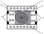
图2为本发明实施例可雾化营养液的MEMS芯片俯视结构示意图。Fig. 2 is a top view structural diagram of a MEMS chip capable of nebulizing nutrient solution according to an embodiment of the present invention.
其中:1、上衬底,2、下衬底,3、多孔阵列,4、通孔阵列,5、营养液仓,6、输液孔,7、PTFE膜,8、氧化硅板,9、Pt温度传感器,10、金属发热丝,11、金属引线,12、橡胶塞,13、密封垫。Among them: 1. Upper substrate, 2. Lower substrate, 3. Porous array, 4. Through hole array, 5. Nutrient solution chamber, 6. Infusion hole, 7. PTFE membrane, 8. Silicon oxide plate, 9. Pt Temperature sensor, 10, metal heating wire, 11, metal lead wire, 12, rubber plug, 13, sealing pad.
具体实施方式detailed description
下面结合本发明实施例的附图对本发明实施例的技术方案进行解释和说明,但下述实施例仅为本发明的优选实施例,并非全部。基于实施方式中的实施例,本领域技术人员在没有做出创造性劳动的前提下所获得其他实施例,都属于本发明的保护范围。The technical solutions of the embodiments of the present invention will be explained and described below in conjunction with the accompanying drawings of the embodiments of the present invention, but the following embodiments are only preferred embodiments of the present invention, not all of them. Based on the examples in the implementation manners, other examples obtained by those skilled in the art without making creative efforts all belong to the protection scope of the present invention.
在下文描述中,出现诸如术语“内”、“外”、“上”、“下”、“左”、“右”等指示方位或者位置关系仅是为了方便描述实施例和简化描述,而不是指示或暗示所指的装置或者元件必须具有特定的方位、以特定的方位构造和操作,因此不能理解为对本发明的限制。In the following description, terms such as "inner", "outer", "upper", "lower", "left", "right" etc. appearing to indicate orientation or positional relationship are only for the convenience of describing the embodiment and simplifying the description, rather than Nothing indicating or implying that a referenced device or element must have a particular orientation, be constructed, and operate in a particular orientation should therefore not be construed as limiting the invention.
一种可雾化营养液的MEMS芯片,请参阅附图1,包括上衬底1、下衬底2、通气模块、营养液仓5、输液孔6、PTFE膜7、氧化硅板8、Pt温度传感器9、金属发热丝10和驱动电路,下衬底2中设有营养液仓5和输液孔6,营养液仓5靠近上衬底1一侧具有开口,输液孔6将营养液仓5与下衬底2外部连通,PTFE膜7封闭开口,上衬底1与下衬底2固定连接,上衬底1中设有通气模块,氧化硅板8固定安装在上衬底1表面,Pt温度传感器9和金属发热丝10均安装在氧化硅板8上,Pt温度传感器9检测金属发热丝10的温度,Pt温度传感器9和金属发热丝10均与驱动电路连接。本实施例通过微机电系统加工工艺,将金属发热丝10、Pt温度传感器9、PTFE膜7以及营养液仓5巧妙地集成为一体,实现了营养液的均匀雾化,有利于人体的吸收,并且生产成本低,硬件体积小,操作便携。上衬底1采用单晶硅材料,下衬底2采用单晶硅或者玻璃材料,下衬底2材料的电阻率高于上衬底1的材料。A MEMS chip capable of atomizing nutrient solution, please refer to attached
通气模块包括多孔阵列3和通孔阵列4,通孔阵列4靠近下衬底2一侧,多孔阵列3位于氧化硅板8与通孔阵列4之间。多孔阵列3的孔径为30纳米至3000纳米,通孔阵列4的孔径为30微米至300微米。多孔阵列3和通孔阵列4向下导热、向上导雾气。The ventilation module includes a
PTFE膜7具有防水透气功能,使得营养液仓5中雾化后的营养液可以通过该膜,而液态的营养液无法通过该膜,从而保证了本实施例雾化功能的正常实现。The
微机电系统雾化营养液的过程为:将营养液从输液孔6注入营养液仓5中,然后用橡胶塞12堵住输液孔6以防止漏液,由于PTFE膜7的存在,液态的营养液无法通过PTFE膜7,因此营养液便被存储在营养液仓5中。此时,通过驱动电路给与金属发热丝10连接的金属引线11施加电流,使得金属发热丝10均匀发热,本实施例微机电系统内部温度持续上升,使得营养液得以雾化,从而由下而上地依次穿过PTFE膜7、通孔阵列4和多孔阵列3,随后穿透出本实施例微机电系统,以供人体吸收。其中,Pt温度传感器9可以实时检测金属发热丝10的温度,当温度超过第一预设值时,驱动电路停止向金属发热丝10供电,从而使得金属发热丝10暂停发热,避免营养液遭到破坏。The process of microelectromechanical system atomizing nutrient solution is: inject the nutrient solution from the
其中,输液孔6内表面加工有螺旋结构,微机电系统包括橡胶塞12,橡胶塞12与输液孔6相配合,防止漏液。螺旋结构能够使橡胶塞12与输液孔6的内表面紧密贴合,实现更良好的密封。Wherein, the inner surface of the
其中,上衬底1与下衬底2之间设有密封垫13。能避免雾化后的营养液经过上衬底1与下衬底2之间粘合的缝隙之间露出。Wherein, a sealing
请参阅附图2,上衬底1表面设有两组金属引线11,金属发热丝10通过一组金属引线11与驱动电路连接,Pt温度传感器9通过另一组金属引线11与驱动电路连接。Pt温度传感器9能够检测到金属发热丝10的温度。Please refer to accompanying drawing 2, two groups of metal leads 11 are arranged on the surface of
其中,金属发热丝10呈螺旋状,使得金属发热丝10在圆域内均匀分布,不同于传统条状发热丝的局部发热,本实施例的螺旋状金属发热丝10更有利于均匀加热。Wherein, the
其中,Pt温度传感器9呈与金属发热丝10相匹配的圆弧状,最大程度上贴近了螺旋状金属发热丝10,有利于温度的采集。当驱动电路检测到Pt温度传感器9的输出温度值大于第一预设值时,驱动电路停止向金属发热丝10供电,当驱动电路检测到Pt温度传感器9的输出温度值小于第二预设值时,驱动电路向金属发热丝10供电。有效避免了温度过高导致营养液营养遭到破坏的问题,同时可以根据患者的需求进行温度调节,从而改变营养液的雾化量。Wherein, the
以上所述,仅为本发明的具体实施方式,但本发明的保护范围并不局限于此,熟悉该本领域的技术人员应该明白本发明包括但不限于附图和上面具体实施方式中描述的内容。任何不偏离本发明的功能和结构原理的修改都将包括在权利要求书的范围中。The above is only a specific embodiment of the present invention, but the scope of protection of the present invention is not limited thereto, and those skilled in the art should understand that the present invention includes but is not limited to the accompanying drawings and the description in the above specific embodiments content. Any modifications that do not depart from the functional and structural principles of the present invention will be included in the scope of the claims.
Claims (10)
Priority Applications (1)
| Application Number | Priority Date | Filing Date | Title |
|---|---|---|---|
| CN202211206603.8ACN115445032A (en) | 2022-09-30 | 2022-09-30 | MEMS chip capable of atomizing nutrient solution |
Applications Claiming Priority (1)
| Application Number | Priority Date | Filing Date | Title |
|---|---|---|---|
| CN202211206603.8ACN115445032A (en) | 2022-09-30 | 2022-09-30 | MEMS chip capable of atomizing nutrient solution |
Publications (1)
| Publication Number | Publication Date |
|---|---|
| CN115445032Atrue CN115445032A (en) | 2022-12-09 |
Family
ID=84307925
Family Applications (1)
| Application Number | Title | Priority Date | Filing Date |
|---|---|---|---|
| CN202211206603.8APendingCN115445032A (en) | 2022-09-30 | 2022-09-30 | MEMS chip capable of atomizing nutrient solution |
Country Status (1)
| Country | Link |
|---|---|
| CN (1) | CN115445032A (en) |
Citations (12)
| Publication number | Priority date | Publication date | Assignee | Title |
|---|---|---|---|---|
| CN102520012A (en)* | 2011-12-06 | 2012-06-27 | 西安交通大学 | MEMS (Micro Electro Mechanical System) technology-based thermal diffusivity sensor chip and manufacturing method thereof |
| CN102593024A (en)* | 2012-01-18 | 2012-07-18 | 中国科学院上海微系统与信息技术研究所 | Method for measuring junction temperature of multi-chip embedded type packaging chip by using integrated resistor |
| CN104768407A (en)* | 2012-09-04 | 2015-07-08 | R·J·雷诺兹烟草公司 | Electronic smoking articles including one or more microheaters |
| CN108158040A (en)* | 2018-01-03 | 2018-06-15 | 云南中烟工业有限责任公司 | The MEMS electronic cigarettes chip and its manufacturing method of a kind of consistent heat generation |
| CN108158039A (en)* | 2018-01-03 | 2018-06-15 | 云南中烟工业有限责任公司 | A kind of MEMS euthermic chips and its manufacturing method for integrating multiple Pt temperature sensors |
| CN208624642U (en)* | 2018-03-30 | 2019-03-22 | 上海新型烟草制品研究院有限公司 | Atomizing core structure and electronic cigarette |
| CN209611997U (en)* | 2019-02-13 | 2019-11-12 | 昆明医科大学第一附属医院 | A kind of wet dressing belt for chemotherapy drug extravasation care |
| CN211750401U (en)* | 2020-01-15 | 2020-10-27 | 河南元亨利贞生物科技有限公司 | Electric heating hot compress medicine bag |
| US20210052008A1 (en)* | 2019-03-25 | 2021-02-25 | China Tobacco Yunnan Industrial Co., Ltd | Plated silicon-based electronic cigarette atomizing chip and preparation method thereof |
| CN214018068U (en)* | 2020-11-18 | 2021-08-24 | 深圳市罗湖区中医院 | Constant temperature hot compress package |
| CN113662250A (en)* | 2021-09-02 | 2021-11-19 | 美满芯盛(杭州)微电子有限公司 | MEMS silicon-based atomizing core and manufacturing method thereof |
| CN114886161A (en)* | 2022-06-07 | 2022-08-12 | 美满芯盛(杭州)微电子有限公司 | MEMS heating atomization core capable of measuring temperature based on Mo heating resistance wire and manufacturing method thereof |
- 2022
- 2022-09-30CNCN202211206603.8Apatent/CN115445032A/enactivePending
Patent Citations (12)
| Publication number | Priority date | Publication date | Assignee | Title |
|---|---|---|---|---|
| CN102520012A (en)* | 2011-12-06 | 2012-06-27 | 西安交通大学 | MEMS (Micro Electro Mechanical System) technology-based thermal diffusivity sensor chip and manufacturing method thereof |
| CN102593024A (en)* | 2012-01-18 | 2012-07-18 | 中国科学院上海微系统与信息技术研究所 | Method for measuring junction temperature of multi-chip embedded type packaging chip by using integrated resistor |
| CN104768407A (en)* | 2012-09-04 | 2015-07-08 | R·J·雷诺兹烟草公司 | Electronic smoking articles including one or more microheaters |
| CN108158040A (en)* | 2018-01-03 | 2018-06-15 | 云南中烟工业有限责任公司 | The MEMS electronic cigarettes chip and its manufacturing method of a kind of consistent heat generation |
| CN108158039A (en)* | 2018-01-03 | 2018-06-15 | 云南中烟工业有限责任公司 | A kind of MEMS euthermic chips and its manufacturing method for integrating multiple Pt temperature sensors |
| CN208624642U (en)* | 2018-03-30 | 2019-03-22 | 上海新型烟草制品研究院有限公司 | Atomizing core structure and electronic cigarette |
| CN209611997U (en)* | 2019-02-13 | 2019-11-12 | 昆明医科大学第一附属医院 | A kind of wet dressing belt for chemotherapy drug extravasation care |
| US20210052008A1 (en)* | 2019-03-25 | 2021-02-25 | China Tobacco Yunnan Industrial Co., Ltd | Plated silicon-based electronic cigarette atomizing chip and preparation method thereof |
| CN211750401U (en)* | 2020-01-15 | 2020-10-27 | 河南元亨利贞生物科技有限公司 | Electric heating hot compress medicine bag |
| CN214018068U (en)* | 2020-11-18 | 2021-08-24 | 深圳市罗湖区中医院 | Constant temperature hot compress package |
| CN113662250A (en)* | 2021-09-02 | 2021-11-19 | 美满芯盛(杭州)微电子有限公司 | MEMS silicon-based atomizing core and manufacturing method thereof |
| CN114886161A (en)* | 2022-06-07 | 2022-08-12 | 美满芯盛(杭州)微电子有限公司 | MEMS heating atomization core capable of measuring temperature based on Mo heating resistance wire and manufacturing method thereof |
Similar Documents
| Publication | Publication Date | Title |
|---|---|---|
| CN107970505B (en) | A portable insulin nebulizer drug delivery device | |
| CN104069571B (en) | Nebulization dosing device for medical nebulization chamber | |
| CN103405835B (en) | Integrated medical vaporizer | |
| CN109876251A (en) | An intelligent nebulizer for pediatric internal medicine | |
| CN107213538B (en) | Medicine storage and atomizing device for aerosol inhalation administration | |
| CN205411859U (en) | Disposable automatic liquid feeding formula atomizing atomizer that heats | |
| CN110013588A (en) | High-performance mesh nebulizer | |
| CN204684370U (en) | A kind of medicinal atomized inhaler controlled based on module | |
| CN115445032A (en) | MEMS chip capable of atomizing nutrient solution | |
| CN209347828U (en) | An atomizing spray device | |
| CN206463303U (en) | A kind of medicinal atomized inhalator | |
| CN209596345U (en) | A kind of nebulizer | |
| CN217091689U (en) | Atomizer capable of automatically switching liquid medicine | |
| CN2456725Y (en) | Inhalation administration and humidifying device through oxygen inhalation control release | |
| CN201727813U (en) | Ultrasonic atomization drug delivery device for both mouth and nose | |
| CN211188609U (en) | Medical multifunctional ultrasonic atomization equipment | |
| WO2018072665A1 (en) | Multi-cavity atomizing apparatus | |
| CN209187543U (en) | A kind of micro- package instrument of drug for Chinese medicine and children prepares nozzle structure | |
| CN113244481A (en) | Split type piezoelectricity driven intelligent insulin pastes | |
| CN209253855U (en) | A kind of microgrid atomizer | |
| CN218961498U (en) | Intelligent atomization device for pediatric nursing | |
| CN204745236U (en) | Atomizing granule heating device with medical atomizer cooperation use | |
| CN216456384U (en) | Nebulizer for pediatric respiratory diseases | |
| CN206045133U (en) | Atomization, the dual-purpose oxygen face mask of humidifying | |
| CN221904843U (en) | Medicine feeding device for medical care |
Legal Events
| Date | Code | Title | Description |
|---|---|---|---|
| PB01 | Publication | ||
| PB01 | Publication | ||
| SE01 | Entry into force of request for substantive examination | ||
| SE01 | Entry into force of request for substantive examination | ||
| RJ01 | Rejection of invention patent application after publication | Application publication date:20221209 | |
| RJ01 | Rejection of invention patent application after publication |