CN115444567A - Systems and methods for instrument interference compensation - Google Patents
Systems and methods for instrument interference compensationDownload PDFInfo
- Publication number
- CN115444567A CN115444567ACN202211061168.4ACN202211061168ACN115444567ACN 115444567 ACN115444567 ACN 115444567ACN 202211061168 ACN202211061168 ACN 202211061168ACN 115444567 ACN115444567 ACN 115444567A
- Authority
- CN
- China
- Prior art keywords
- joints
- computer
- transformation
- point
- interest
- Prior art date
- Legal status (The legal status is an assumption and is not a legal conclusion. Google has not performed a legal analysis and makes no representation as to the accuracy of the status listed.)
- Pending
Links
Images


Classifications
- B—PERFORMING OPERATIONS; TRANSPORTING
- B25—HAND TOOLS; PORTABLE POWER-DRIVEN TOOLS; MANIPULATORS
- B25J—MANIPULATORS; CHAMBERS PROVIDED WITH MANIPULATION DEVICES
- B25J9/00—Programme-controlled manipulators
- B25J9/16—Programme controls
- B25J9/1628—Programme controls characterised by the control loop
- B25J9/1641—Programme controls characterised by the control loop compensation for backlash, friction, compliance, elasticity in the joints
- A—HUMAN NECESSITIES
- A61—MEDICAL OR VETERINARY SCIENCE; HYGIENE
- A61B—DIAGNOSIS; SURGERY; IDENTIFICATION
- A61B34/00—Computer-aided surgery; Manipulators or robots specially adapted for use in surgery
- A61B34/30—Surgical robots
- A—HUMAN NECESSITIES
- A61—MEDICAL OR VETERINARY SCIENCE; HYGIENE
- A61B—DIAGNOSIS; SURGERY; IDENTIFICATION
- A61B34/00—Computer-aided surgery; Manipulators or robots specially adapted for use in surgery
- A61B34/20—Surgical navigation systems; Devices for tracking or guiding surgical instruments, e.g. for frameless stereotaxis
- A—HUMAN NECESSITIES
- A61—MEDICAL OR VETERINARY SCIENCE; HYGIENE
- A61B—DIAGNOSIS; SURGERY; IDENTIFICATION
- A61B34/00—Computer-aided surgery; Manipulators or robots specially adapted for use in surgery
- A61B34/70—Manipulators specially adapted for use in surgery
- A—HUMAN NECESSITIES
- A61—MEDICAL OR VETERINARY SCIENCE; HYGIENE
- A61B—DIAGNOSIS; SURGERY; IDENTIFICATION
- A61B90/00—Instruments, implements or accessories specially adapted for surgery or diagnosis and not covered by any of the groups A61B1/00 - A61B50/00, e.g. for luxation treatment or for protecting wound edges
- A61B90/36—Image-producing devices or illumination devices not otherwise provided for
- A61B90/361—Image-producing devices, e.g. surgical cameras
- A—HUMAN NECESSITIES
- A61—MEDICAL OR VETERINARY SCIENCE; HYGIENE
- A61B—DIAGNOSIS; SURGERY; IDENTIFICATION
- A61B90/00—Instruments, implements or accessories specially adapted for surgery or diagnosis and not covered by any of the groups A61B1/00 - A61B50/00, e.g. for luxation treatment or for protecting wound edges
- A61B90/50—Supports for surgical instruments, e.g. articulated arms
- B—PERFORMING OPERATIONS; TRANSPORTING
- B25—HAND TOOLS; PORTABLE POWER-DRIVEN TOOLS; MANIPULATORS
- B25J—MANIPULATORS; CHAMBERS PROVIDED WITH MANIPULATION DEVICES
- B25J19/00—Accessories fitted to manipulators, e.g. for monitoring, for viewing; Safety devices combined with or specially adapted for use in connection with manipulators
- B25J19/0004—Braking devices
- B—PERFORMING OPERATIONS; TRANSPORTING
- B25—HAND TOOLS; PORTABLE POWER-DRIVEN TOOLS; MANIPULATORS
- B25J—MANIPULATORS; CHAMBERS PROVIDED WITH MANIPULATION DEVICES
- B25J19/00—Accessories fitted to manipulators, e.g. for monitoring, for viewing; Safety devices combined with or specially adapted for use in connection with manipulators
- B25J19/02—Sensing devices
- B25J19/021—Optical sensing devices
- B—PERFORMING OPERATIONS; TRANSPORTING
- B25—HAND TOOLS; PORTABLE POWER-DRIVEN TOOLS; MANIPULATORS
- B25J—MANIPULATORS; CHAMBERS PROVIDED WITH MANIPULATION DEVICES
- B25J9/00—Programme-controlled manipulators
- B25J9/06—Programme-controlled manipulators characterised by multi-articulated arms
- B—PERFORMING OPERATIONS; TRANSPORTING
- B25—HAND TOOLS; PORTABLE POWER-DRIVEN TOOLS; MANIPULATORS
- B25J—MANIPULATORS; CHAMBERS PROVIDED WITH MANIPULATION DEVICES
- B25J9/00—Programme-controlled manipulators
- B25J9/16—Programme controls
- B25J9/1602—Programme controls characterised by the control system, structure, architecture
- B25J9/1607—Calculation of inertia, jacobian matrixes and inverses
- B—PERFORMING OPERATIONS; TRANSPORTING
- B25—HAND TOOLS; PORTABLE POWER-DRIVEN TOOLS; MANIPULATORS
- B25J—MANIPULATORS; CHAMBERS PROVIDED WITH MANIPULATION DEVICES
- B25J9/00—Programme-controlled manipulators
- B25J9/16—Programme controls
- B25J9/1628—Programme controls characterised by the control loop
- B25J9/1653—Programme controls characterised by the control loop parameters identification, estimation, stiffness, accuracy, error analysis
- B—PERFORMING OPERATIONS; TRANSPORTING
- B25—HAND TOOLS; PORTABLE POWER-DRIVEN TOOLS; MANIPULATORS
- B25J—MANIPULATORS; CHAMBERS PROVIDED WITH MANIPULATION DEVICES
- B25J9/00—Programme-controlled manipulators
- B25J9/16—Programme controls
- B25J9/1679—Programme controls characterised by the tasks executed
- B25J9/1682—Dual arm manipulator; Coordination of several manipulators
- A—HUMAN NECESSITIES
- A61—MEDICAL OR VETERINARY SCIENCE; HYGIENE
- A61B—DIAGNOSIS; SURGERY; IDENTIFICATION
- A61B34/00—Computer-aided surgery; Manipulators or robots specially adapted for use in surgery
- A61B34/20—Surgical navigation systems; Devices for tracking or guiding surgical instruments, e.g. for frameless stereotaxis
- A61B2034/2046—Tracking techniques
- A61B2034/2059—Mechanical position encoders
- A—HUMAN NECESSITIES
- A61—MEDICAL OR VETERINARY SCIENCE; HYGIENE
- A61B—DIAGNOSIS; SURGERY; IDENTIFICATION
- A61B34/00—Computer-aided surgery; Manipulators or robots specially adapted for use in surgery
- A61B34/30—Surgical robots
- A61B2034/305—Details of wrist mechanisms at distal ends of robotic arms
- A—HUMAN NECESSITIES
- A61—MEDICAL OR VETERINARY SCIENCE; HYGIENE
- A61B—DIAGNOSIS; SURGERY; IDENTIFICATION
- A61B90/00—Instruments, implements or accessories specially adapted for surgery or diagnosis and not covered by any of the groups A61B1/00 - A61B50/00, e.g. for luxation treatment or for protecting wound edges
- A61B90/36—Image-producing devices or illumination devices not otherwise provided for
- A61B90/37—Surgical systems with images on a monitor during operation
- A61B2090/373—Surgical systems with images on a monitor during operation using light, e.g. by using optical scanners
- A—HUMAN NECESSITIES
- A61—MEDICAL OR VETERINARY SCIENCE; HYGIENE
- A61B—DIAGNOSIS; SURGERY; IDENTIFICATION
- A61B90/00—Instruments, implements or accessories specially adapted for surgery or diagnosis and not covered by any of the groups A61B1/00 - A61B50/00, e.g. for luxation treatment or for protecting wound edges
- A61B90/50—Supports for surgical instruments, e.g. articulated arms
- A61B2090/508—Supports for surgical instruments, e.g. articulated arms with releasable brake mechanisms
- A—HUMAN NECESSITIES
- A61—MEDICAL OR VETERINARY SCIENCE; HYGIENE
- A61B—DIAGNOSIS; SURGERY; IDENTIFICATION
- A61B34/00—Computer-aided surgery; Manipulators or robots specially adapted for use in surgery
- A61B34/30—Surgical robots
- A61B34/35—Surgical robots for telesurgery
- Y—GENERAL TAGGING OF NEW TECHNOLOGICAL DEVELOPMENTS; GENERAL TAGGING OF CROSS-SECTIONAL TECHNOLOGIES SPANNING OVER SEVERAL SECTIONS OF THE IPC; TECHNICAL SUBJECTS COVERED BY FORMER USPC CROSS-REFERENCE ART COLLECTIONS [XRACs] AND DIGESTS
- Y10—TECHNICAL SUBJECTS COVERED BY FORMER USPC
- Y10S—TECHNICAL SUBJECTS COVERED BY FORMER USPC CROSS-REFERENCE ART COLLECTIONS [XRACs] AND DIGESTS
- Y10S901/00—Robots
- Y10S901/02—Arm motion controller
Landscapes
- Engineering & Computer Science (AREA)
- Health & Medical Sciences (AREA)
- Surgery (AREA)
- Life Sciences & Earth Sciences (AREA)
- Robotics (AREA)
- Mechanical Engineering (AREA)
- Public Health (AREA)
- Nuclear Medicine, Radiotherapy & Molecular Imaging (AREA)
- Heart & Thoracic Surgery (AREA)
- Medical Informatics (AREA)
- Molecular Biology (AREA)
- Animal Behavior & Ethology (AREA)
- Biomedical Technology (AREA)
- General Health & Medical Sciences (AREA)
- Veterinary Medicine (AREA)
- Pathology (AREA)
- Oral & Maxillofacial Surgery (AREA)
- Physics & Mathematics (AREA)
- Mathematical Physics (AREA)
- Automation & Control Theory (AREA)
- Manipulator (AREA)
- Accommodation For Nursing Or Treatment Tables (AREA)
Abstract
Translated fromChinese
Description
Translated fromChinese本申请是2015年10月27日提交的名称为“用于器械干扰补偿的系统和 方法”的中国专利申请2019109857431的分案申请,其中中国专利申请 2019109857431是2015年10月27日提交的名称为“用于器械干扰补偿的系 统和方法”的中国专利申请2015800561206(PCT/US2015/057669)的分案申 请。This application is a divisional application of the Chinese patent application 2019109857431 filed on October 27, 2015, entitled "System and method for device interference compensation", wherein the Chinese patent application 2019109857431 is filed on October 27, 2015, and the title is Divisional application of Chinese patent application 2015800561206 (PCT/US2015/057669) for "System and method for device interference compensation".
相关申请related application
本公开要求于2014年10月27日提交的标题为“用于集成手术台的系统 和方法(System and Method for Integrated Operating Table)”的美国临时专利 申请第62/069,245号以及于2015年3月17日提交的标题为“用于减少工具 干扰的系统和方法(Systemand Method for Reducing Tool Disturbances)”美国 临时专利申请号62/134,212的优先权,这两个公开通过引用以其全文结合在 此。This disclosure claims U.S. Provisional Patent Application No. 62/069,245, entitled "System and Method for Integrated Operating Table," filed October 27, 2014 and filed on March 2015. Priority to U.S. Provisional Patent Application No. 62/134,212, entitled "System and Method for Reducing Tool Disturbances," filed on the 17th, both publications are hereby incorporated by reference in their entirety.
技术领域technical field
本公开总体上涉及具有铰接臂的设备的操作,并且更具体地涉及减少对 器械姿态的外部干扰。The present disclosure relates generally to the operation of devices having articulated arms, and more particularly to reducing external disturbances to the posture of the instrument.
背景技术Background technique
越来越多的设备正在被替换为自主和半自主电子设备。这在现今的医院 里面尤其如此,在手术室、介入疗室(interventional suite)、重症监护病房、 急诊室等中具有大批自主的和半自主的电子设备。例如,玻璃温度计和水银 温度计由电子温度计取代,静脉滴注管线现在包括电子监测器和流量调节器, 并且传统的手持式外科手术器械正由计算机辅助医疗设备所取代。More and more devices are being replaced with autonomous and semi-autonomous electronics. This is especially true in today's hospitals, with large numbers of autonomous and semi-autonomous electronic devices in operating rooms, interventional suites, intensive care units, emergency rooms, and the like. For example, glass and mercury thermometers are being replaced by electronic thermometers, IV drip lines now include electronic monitors and flow regulators, and traditional hand-held surgical instruments are being replaced by computer-assisted medical devices.
这些电子设备为操作它们的人员提供了优势和挑战。许多这些电子设备 都可以使一个或多个铰接臂和/或末端执行器进行自主或半自主运动。这些一 个或多个铰接臂和/或末端执行器每个都包括支持这些铰接臂和/或末端执行 器的运动的连杆和铰接关节的组合。在许多情况下,对这些铰接关节进行操 纵以获得位于相应铰接臂和/或末端执行器的连杆和铰接关节的远端处的相应 器械的预期位置和/或取向(统称为期望姿态)。靠近该器械的每个铰接关节为 相应的铰接臂和/或末端执行器提供至少一个自由度,该自由度可以用于操纵 相应器械的位置和/或取向。在许多情况下,相应的铰接臂和/或末端执行器可 以包括允许控制相应器械的X位置、Y位置和Z位置(统称为平移移动)以 及相应器械的滚转、俯仰和偏摆取向(统称为旋转移动)的至少六个自由度。 为了在控制相应器械的姿态方面提供更大的灵活性,相应的铰接臂和/或末端 执行器通常被设计成包括冗余自由度。当存在冗余自由度时,可以使用这些 铰接关节的位置和/或取向的多个不同组合来获得相应器械的相同姿态。These electronic devices present advantages and challenges to those who operate them. Many of these electronic devices enable autonomous or semi-autonomous movement of one or more articulated arms and/or end effectors. These one or more articulated arms and/or end effectors each include a combination of linkages and articulation joints that support the motion of the articulated arms and/or end effectors. In many cases, these articulation joints are manipulated to achieve desired positions and/or orientations (collectively referred to as desired poses) of respective instruments at the distal ends of the links and articulation joints of the respective articulated arms and/or end effectors. Each articulated joint adjacent the instrument provides at least one degree of freedom for a corresponding articulated arm and/or end effector that can be used to manipulate the position and/or orientation of the corresponding instrument. In many cases, the corresponding articulated arms and/or end effectors may include elements that allow control of the corresponding instrument's X, Y, and Z positions (collectively referred to as translational movement) as well as the corresponding instrument's roll, pitch, and yaw orientation (collectively referred to as At least six degrees of freedom for rotational movement). To provide greater flexibility in controlling the pose of the corresponding instrument, the corresponding articulated arm and/or end effector are often designed to include redundant degrees of freedom. When there are redundant degrees of freedom, multiple different combinations of the positions and/or orientations of these articulation joints can be used to obtain the same pose of the corresponding instrument.
当具有铰接臂的设备用于医疗程序时,并不罕见的是铰接臂中的一个或 多个可以在端口部位处与患者对接,使得可以利用器械和/或其它末端执行器 来对于患者的内部解剖结构执行程序。根据该程序,可能期望释放对该铰接 臂的一个或多个关节的锁和/或制动器,以便重新定位该铰接臂的至少一部分。 当释放该锁和/或制动器时,这样可能导致该铰接臂(更重要的是定位在该患 者体内的器械和/或末端执行器的尖端)的位置和/或取向的不期望的移动。这 种不期望的移动可能导致伤害患者、伤害铰接臂和/或末端执行器附近的人员、 损坏铰接臂和/或末端执行器、损坏铰接臂和/或末端执行器附近的其他设备、 破坏无菌区和/或其它不期望的结果。When a device with articulated arms is used in a medical procedure, it is not uncommon for one or more of the articulated arms to interface with the patient at a port site so that instruments and/or other end effectors can be used to access the patient's interior. The anatomy performs the procedure. Depending on the procedure, it may be desirable to release locks and/or brakes on one or more joints of the articulated arm in order to reposition at least a portion of the articulated arm. This may result in undesired movement of the position and/or orientation of the articulated arm (and more importantly the tip of the instrument and/or end effector positioned within the patient) when the lock and/or brake are released. This undesired movement could result in injury to the patient, injury to persons near the articulating arm and/or end effector, damage to the articulating arm and/or end effector, damage to other equipment near the articulating arm and/or end effector, damage to Bacteria and/or other undesired results.
因此,所期望的是,当铰接臂的一个或多个关节的制动器和/或锁被释放 时,使铰接臂中的一个或多个关节校正器械、铰接臂和/或末端执行器中的不 期望的移动。Therefore, it is desirable that when the brake and/or lock of one or more joints of the articulated arm are released, one or more joints in the articulated arm correct the inaccuracies in the instrument, the articulated arm, and/or the end effector. desired move.
发明内容Contents of the invention
与一些实施例一致,一种计算机辅助医疗设备包括铰接臂上的第一关节 组、铰接臂上的第二关节组、以及耦接到该第一关节组和该第二关节组的控 制单元。在一些实施例中,该控制单元被配置为确定由释放一个或多个制动 器引起的对第一关节组的干扰并且使用第二关节组来补偿干扰,以减少该铰 接臂上的关注点的位置的运动。Consistent with some embodiments, a computer-aided medical device includes a first set of joints on an articulated arm, a second set of joints on an articulated arm, and a control unit coupled to the first set of joints and the second set of joints. In some embodiments, the control unit is configured to determine a disturbance to the first set of joints caused by releasing the one or more brakes and to compensate for the disturbance using the second set of joints to reduce the position of the point of interest on the articulated arm exercise.
根据一些实施例,一种控制医疗设备中的运动的方法包括:确定第一保 存变换,该第一保存变换是在干扰之前跨越该医疗设备的铰接臂的第一关节 组的两个坐标系之间的变换;确定第二保存变换,该第二保存变换是跨越该 铰接臂的第二关节组的两个坐标系之间的变换;接收该干扰,该干扰对该第 一关节组中的一个或多个关节的位置进行干扰;确定第三变换,该第三变换 是在该干扰之后跨越该第一关节组的两个坐标系之间的变换;并且确定由该 干扰引起的关注点的预测运动。在一些示例中,由该干扰引起的关注点的预测运动包括:计算基于第一保存变换和第二保存变换的第一位置确定与基于 第三变换和第二保存变换的第二位置确定之间的差。According to some embodiments, a method of controlling motion in a medical device includes determining a first preserved transformation between two coordinate systems spanning a first set of joints of an articulated arm of the medical device prior to disturbance transformation between; determine a second preserved transformation, the second preserved transformation is a transformation between two coordinate systems spanning the second joint group of the articulated arm; receive the disturbance, the disturbance to one of the first joint group or multiple joints; determining a third transformation that is a transformation between two coordinate systems spanning the first joint group after the disturbance; and determining a prediction of a point of interest caused by the disturbance sports. In some examples, predicting the motion of the point of interest caused by the disturbance includes calculating the difference between the first position determination based on the first and second preserved transformations and the second position determination based on the third and second preserved transformations poor.
根据一些实施例,一种控制医疗设备中的运动的方法包括:确定第一保 存变换,该第一保存变换是在干扰之前跨越医疗设备的铰接臂的第一关节组 的两个坐标系之间的变换;确定第二保存变换,该第二保存变换是跨越该铰 接臂的第二关节组的两个坐标系之间的变换;接收干扰,该干扰对第一关节 组中的一个或多个关节的位置进行干扰;确定第三变换,该第三变换是在该 干扰之后跨越第一关节组的两个坐标系之间的变换;并且确定由该干扰引起 的关注点的预测运动。在一些示例中,确定由该干扰引起的关注点的预测运动的步骤包括:计算基于第一保存变换和第二保存变换的第一位置确定与基 于该第三变换和第二保存变换的第二位置确定之间的差。According to some embodiments, a method of controlling motion in a medical device includes determining a first preserved transformation between two coordinate systems spanning a first set of joints of an articulated arm of a medical device prior to disturbance transformation; determine a second preservation transformation, the second preservation transformation is a transformation between two coordinate systems across the second joint group of the articulated arm; receive interference, the interference to one or more of the first joint group perturbing the positions of the joints; determining a third transformation that is a transformation between the two coordinate systems spanning the first set of joints after the perturbation; and determining a predicted motion of the point of interest caused by the perturbation. In some examples, the step of determining the predicted motion of the point of interest caused by the disturbance includes calculating the first position determination based on the first and second preserved transformations and the second position determination based on the third and second preserved transformations. The difference between location determination.
根据一些实施例,一种计算机辅助医疗设备包括:具有成像设备的第一 铰接臂、具有末端执行器的第二铰接臂、耦接到该第一铰接臂和第二铰接臂 的控制单元。在一些示例中,该控制单元被配置为:设置第一参考系,该第 一参考系基于成像设备在第一时间的位置,允许对第一铰接臂的第一干扰使 该成像设备移动离开该成像设备在第一时间的位置,接收用于移动末端执行 器的命令,以及将用于从第一参考系移动末端执行器的命令变换成用于在该 末端执行器的参考系中移动该末端执行器的命令。According to some embodiments, a computer assisted medical device includes a first articulated arm having an imaging device, a second articulated arm having an end effector, a control unit coupled to the first articulated arm and the second articulated arm. In some examples, the control unit is configured to: set a first frame of reference based on the position of the imaging device at a first time, allowing a first disturbance to the first articulated arm to move the imaging device away from the The position of the imaging device at a first time, receiving commands for moving the end effector, and transforming the commands for moving the end effector from a first frame of reference to moving the end effector in the end effector's frame of reference device commands.
与一些实施例一致,一种包括多个机器可读指令的非暂时性机器可读介 质,这些机器可读指令在由与医疗设备相关联的一个或多个处理器执行时适 于使该一个或多个处理器执行包括以下步骤的方法:确定第一保存变换,该 第一保存变换是在干扰之前跨越该医疗设备的铰接臂的第一关节组的两个坐 标系之间的变换;确定第二保存变换,该第二保存变换是跨越该铰接臂的第 二关节组的两个坐标系之间的变换;接收干扰,该干扰对该第一关节组中的 一个或多个关节的位置进行干扰;确定第三变换,该第三变换是在该干扰之后跨越该第一关节组的两个坐标系之间的变换;并且确定由该干扰引起的关 注点的预测运动。在一些示例中,确定由该干扰引起的关注点的预测运动的 步骤包括:计算基于第一保存变换和第二保存变换的第一位置确定与基于第 三变换和第二保存变换的第二位置确定之间的差。Consistent with some embodiments, a non-transitory machine-readable medium comprising a plurality of machine-readable instructions adapted, when executed by one or more processors associated with a medical device, to cause the one or a plurality of processors performing a method comprising the steps of: determining a first preserved transformation, the first preserved transformation being a transformation between two coordinate systems spanning a first set of joints of an articulated arm of the medical device prior to the disturbance; determining a second preservation transformation that is a transformation between two coordinate systems spanning a second joint group of the articulated arm; receiving a disturbance that interferes with the position of one or more joints in the first joint group performing a disturbance; determining a third transformation, the third transformation being a transformation between two coordinate systems spanning the first joint group after the disturbance; and determining a predicted motion of the point of interest caused by the disturbance. In some examples, determining the predicted motion of the point of interest caused by the disturbance includes computing a first position determination based on the first and second preserved transformations and a second position determination based on the third and second preserved transformations Determine the difference between.
附图描述Description of drawings
图1是根据一些实施例的计算机辅助系统的简化图。Figure 1 is a simplified diagram of a computer-aided system according to some embodiments.
图2是示出根据一些实施例的计算机辅助系统的简化图。Figure 2 is a simplified diagram illustrating a computer-aided system according to some embodiments.
图3是根据一些实施例的计算机辅助医疗系统的运动学模型的简化图。Figure 3 is a simplified diagram of a kinematic model of a computer assisted medical system according to some embodiments.
图4是交错释放铰接臂上的制动器的方法的简化图。Figure 4 is a simplified diagram of the method of staggered release of the brakes on the articulating arms.
图5是使用第二关节组来补偿从一个关节组到关注点的干扰的方法的简 化图。Figure 5 is a simplified diagram of a method of using a second joint set to compensate for interference from one joint set to a point of interest.
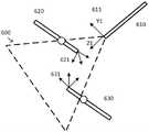
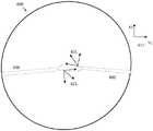
图6A是示出示例性摄像头视图和坐标系统的透视图的简化图。6A is a simplified diagram illustrating a perspective view of an exemplary camera view and coordinate system.
图6B是从传感器或显示器及相关坐标系统的角度示出摄像头视图的简 化图。Figure 6B is a simplified diagram showing a camera view from the perspective of a sensor or display and associated coordinate system.
图7是基于用户命令移动铰接臂同时对该铰接臂中的一个或多个关节的 干扰进行补偿的方法的简化图。7 is a simplified diagram of a method of moving an articulated arm based on user commands while compensating for disturbances in one or more joints in the articulated arm.
图8A-8G是示出结合了本文所述的集成计算机辅助设备和可移动外科手 术台特征的各种计算机辅助设备系统架构的简化示意图。8A-8G are simplified schematic diagrams illustrating various computer-aided device system architectures incorporating the integrated computer-aided device and movable surgical table features described herein.
在附图中,具有相同标记的元件具有相同的或类似的功能。In the drawings, elements with the same symbols have the same or similar functions.
具体实施方式detailed description
在以下描述中,阐明了具体细节以便描述与本公开一致的一些实施例。 然而,对于本领域技术人员显而易见的是,可以在没有这些特定细节中的一 些或所有细节的情况下实践一些实施例。在此公开的具体实施例是示例性的, 而不是限制性的。本领域的技术人员可以实现落入本公开的范围和精神内的 其他元件(尽管没有特别说明)。另外,为了避免不必要的重复,被示为且被 描述为与一个实施例相关的一个或多个特征可与其他实施例相结合,除非另 外具体说明或者该一个或多个特征会使实施例是非功能性的。术语“包括” 意味着包括但不限于,且所包括的一个或多个单独的项目中的每一个应当被 认为是可选的,除非另有说明。类似地,术语“可以”表示项目是可选的。In the following description, specific details are set forth in order to describe some embodiments consistent with the present disclosure. It will be apparent, however, to one skilled in the art that some embodiments may be practiced without some or all of these specific details. The specific embodiments disclosed herein are illustrative rather than restrictive. Those skilled in the art may implement other elements that fall within the scope and spirit of the present disclosure (although not specifically stated). In addition, to avoid unnecessary repetition, one or more features shown and described in relation to one embodiment may be combined with other embodiments, unless specifically stated otherwise or the one or more features make the embodiment is non-functional. The term "comprising" means including but not limited to, and each of the individual item(s) included should be considered optional unless otherwise stated. Similarly, the term "may" indicates that the item is optional.
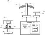
图1是根据一些实施例的计算机辅助系统100的简化图。如图1所示, 计算机辅助系统100包括具有一个或多个可移动臂或铰接臂120的设备110。 一个或多个铰接臂120中的每一个铰接臂支撑一个或多个末端执行器。在一 些实例中,设备110可以与计算机辅助外科手术设备一致。一个或多个铰接 臂120每个都为安装到至少一个铰接臂120的远端的一个或多个器械、外科 手术器械、成像设备和/或类似物提供支撑。在一些实施例中,设备110和操 作者工作站可以对应于由加利福尼亚州(California)森尼维耳市(Sunnyvale)的直觉外科手术公司(Intuitive Surgical,Inc.)商业化的da
设备110经由接口耦接到控制单元130。该接口可以包括一个或多个无线 链路、线缆、连接器和/或总线,并且还可以包括具有一个或多个网络交换和/ 或路由设备的一个或多个网络。控制单元130包括耦接到存储器150的处理 器140。由处理器140对控制单元130的操作进行控制。并且,尽管控制单元 130显示只有一个处理器140,可以理解的是处理器140可以表示控制单元130 中的一个或多个中央处理单元、多核处理器、微处理器、微控制器、数字信 号处理器、现场可编程门阵列(FPGA)、专用集成电路(ASIC)和/或类似设 备。控制单元130可以被实现为加入到计算设备中的一个独立子系统和/或板, 或是实现为虚拟机。在一些实施例中,控制单元可被包括为操作者工作站的 一部分,和/或与该操作者工作站分离地但与之协同地操作。控制单元的一些 实例(如控制单元130)可以包括非暂时性的、有形的机器可读介质,其包括 当由一个或多个处理器(例如处理器140)运行时可导致该一个或多个处理器 来执行方法400的过程的可执行代码。The
存储器150用于存储由控制单元130执行的软件和/或在控制单元130的 操作期间使用的一个或多个数据结构。存储器150可包括一种或多种类型的 机器可读介质。一些普通形式的机器可读介质可包括软盘、软磁盘、硬盘、 磁带、任何其他磁性介质、CD-ROM、任何其他光学介质、穿孔卡、纸带、 具有孔洞图案的任何其他物理介质、RAM、PROM、EPROM、FLASH-EPROM、 任何其他存储器芯片或盒、和/或处理器或计算机适于读取的任何其他介质。Memory 150 is used to store software executed by control unit 130 and/or one or more data structures used during operation of control unit 130. Memory 150 may include one or more types of machine-readable media. Some common forms of machine-readable media may include floppy disks, floppy disks, hard disks, magnetic tape, any other magnetic media, CD-ROMs, any other optical media, punched cards, paper tape, any other physical media with a pattern of holes, RAM, PROM , EPROM, FLASH-EPROM, any other memory chip or cartridge, and/or any other medium suitable for reading by a processor or computer.
如同所示的,存储器150包括支持设备110的自主和/或半自主控制的运 动控制应用程序160。运动控制应用程序160可以包括一个或多个应用程序编 程接口(API),用于从设备110接收位置、运动和/或其他感测信息,与其他 控制单元交换和其他设备(如外科手术台和/或成像设备)相关的位置、运动 和/或避免碰撞的信息,和/或规划设备110、铰接臂120和/或设备110的末端 执行器的运动和/或在该规划中进行辅助。并且,尽管运动控制应用程序160 被描述为软件应用程序,但是运动控制应用程序160可以使用硬件、软件和/ 或硬件和软件的组合来实现。As shown, memory 150 includes a
在一些实施例中,可以在手术室和/或介入疗室中找到计算机辅助系统 100。并且,尽管计算机辅助系统100仅包括一个具有两个铰接臂120的设备 110,但是普通技术人员将理解,计算机辅助系统100可以包括具有与设备110 的设计类似和/或不同的铰接臂和/或末端执行器的任何数量的设备。在一些示 例中,这些设备中的每一个可以包括更少或更多的铰接臂和/或末端执行器。In some embodiments, computer-aided
计算机辅助系统100还包括外科手术台170。类似于一个或多个铰接臂 120,外科手术台170支持台顶部180相对于外科手术台170的底座的铰接式 移动。在一些示例中,台顶部180的铰接式移动可以包括用于改变台顶部180 的高度、倾斜、滑动、特伦德伦伯卧位取向和/或类似方面的支持。尽管未示 出,但外科手术台170可以包括一个或多个控制输入,如用于控制台顶部180 的位置和/或取向的外科手术台命令单元。在一些实施例中,外科手术台170 可以对应于由德国通快医疗系统有限公司(Trumpf Medical Systems GmbH)商业化的一种或多种外科手术台。Computer-aided
外科手术台170还经由相应的接口耦接到控制单元130。该接口可以包括 一个或多个无线链路、线缆、连接器和/或总线,并且还可以包括具有一个或 多个网络交换和/或路由设备的一个或多个网络。在一些实施例中,外科手术 台170可以耦接到与控制单元130不同的控制单元。在一些示例中,运动控 制应用程序160可以包括用于接收与外科手术台170和/或台顶部180相关联 的位置、运动和/或其他感测信息的一个或多个应用程序编程接口(API)。在 一些示例中,运动控制应用程序160可以有助于与碰撞避免相关联的运动规划,适应和/或避免关节和连杆中的运动范围极限以及移动铰接臂、器械、末 端执行器、外科手术台部件等来补偿这些铰接臂、器械、末端执行器、外科 手术台部件等中的其他运动,调整观察设备(如内窥镜)以在该观察设备的 视场内维持和/或放置关注区域和/或一个或多个器械或末端执行器。在一些示 例中,运动控制应用程序160可以规划和/或辅助外科手术台170和/或台顶部 180的运动的规划。在一些示例中,运动控制应用程序160可以防止外科手术 台170和/或台顶部180的运动,如通过使用外科手术台命令单元来防止外科 手术台170和/或台顶部180的移动。在一些示例中,运动控制应用程序160 可以帮助将设备110与外科手术台170配准,以便得知设备110和外科手术 台170之间的几何关系。在一些示例中,该几何关系可以包括为设备110和 外科手术台170保持的坐标系之间的平移和/或一次或多次旋转。The surgical table 170 is also coupled to the control unit 130 via a corresponding interface. The interface may include one or more wireless links, cables, connectors and/or buses, and may also include one or more networks with one or more network switching and/or routing devices. In some embodiments, surgical table 170 may be coupled to a different control unit than control unit 130. In some examples,
控制单元130还可以经由接口耦接到操作者工作站190。操作者工作站 190可以由操作者(如外科医生)使用以控制铰接臂120和末端执行器的移动 和/或操作。为了支持铰接臂120和末端执行器的操作,操作者工作站190包 括用于显示铰接臂120和/或末端执行器中的一个或多个的至少一部分的图像 的显示系统192。例如,在铰接臂120和/或末端执行器正在使用时,当操作 者看到铰接臂120和/或末端执行器是不现实的和/或不可能的时,可以使用显 示系统192。在一些实施例中,显示系统192显示来自由铰接臂120之一或第三铰接臂(未示出)控制的视频捕捉设备(如内窥镜)的视频图像。The control unit 130 may also be coupled to an
操作者工作站190包括具有一个或多个输入控件195或主控件195的控 制台工作空间,输入控件195或主控件195可以用于操作设备110、铰接臂 120和/或安装在铰接臂120上的末端执行器。输入控件195中的每一个可以 耦接到它们自己的铰接臂的远端,使得输入控件195的移动通过操作者工作 站190检测并被传送到控制单元130。为了提供改进的人体工程学,该控制台 工作空间还可以包括一个或多个支持物(如臂靠197),操作者可以在操纵输 入控件195的同时将他们的手臂搁置在臂靠上。在一些示例中,显示系统192 和输入控件195可以由该操作者使用来远程操作铰接臂120和/或安装在铰接 臂120上的末端执行器。在一些实施例中,设备110、操作者工作站190和控 制单元130可以对应于由加利福尼亚州(California)森尼维耳市(Sunnyvale) 的直觉外科手术公司(Intuitive Surgical,Inc.)商业化的da
在一些实施例中,其他配置和/或架构可以与计算机辅助系统100一起使 用。在一些示例中,控制单元130可以被包括作为操作者工作站190和/或设 备110的一部分。在一些实施例中,可以在手术室和/或介入疗室中找到计算 机辅助系统100。并且,尽管计算机辅助系统100仅包括具有两个铰接臂120 的一个设备110,但是普通技术人员将理解,计算机辅助系统100可以包括具 有与设备110类似和/或不同设计的铰接臂和/或末端执行器的任何数量的设 备。在一些示例中,这些设备中的每一个可以包括更少或更多的铰接臂120和/或末端执行器。另外,可以存在附加工作站190以控制可以附接到设备110 的附加臂。另外,在一些实施例中,工作站190可以具有用于控制外科手术 台170的控件。In some embodiments, other configurations and/or architectures may be used with computer-aided
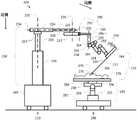
图2是示出根据一些实施例的计算机辅助系统200的简化图。例如,计 算机辅助系统200可以与计算机辅助系统100一致。如图2所示,计算机辅 助系统200包括具有一个或多个铰接臂的计算机辅助设备210和外科手术台 280。虽然在图2中未示出,但是计算机辅助设备210和外科手术台280使用 一个或多个接口和一个或多个控制单元而耦接在一起,使得用于执行计算机 辅助设备210的铰接臂的运动的运动控制应用程序得知至少关于外科手术台 280的运动信息。FIG. 2 is a simplified diagram illustrating a computer-aided
计算机辅助设备210包括各种连杆和关节。在图2的实施例中,该计算 机辅助设备通常分为三组不同的连杆和关节。从装配结构220的近端开始的 是可移动台车215或患者侧台车215。耦接到该装配结构的远端的是形成铰接 臂的一组连杆和装配关节240。并且,耦接到装配关节240的远端的是多关节 操纵器260。在一些示例中,一组装配关节240和操纵器260可以对应于铰接 臂120中的一个。并且,尽管该计算机辅助设备仅示出具有一组装配关节240 及相应的操纵器260,但是普通技术人员将理解,该计算机辅助设备可以包括多于一组的装配关节240及相应的操纵器260,使得该计算机辅助设备配备有 多个铰接臂。Computer aided
如同所示的,计算机辅助设备210安装在可移动台车215上。可移动台 车215使得该计算机辅助设备210能够从一个位置被运往另一个位置,例如 在手术室之间或在手术室内,以更好地将该计算机辅助设备定位在外科手术 台280附近。装配结构220安装在可移动台车215上。如图2所示,装配结 构220包括两部分式柱,该柱包括柱连杆221和连杆222。耦接到柱连杆222 的上端或远端的是肩关节223。耦接到肩关节223的是包括悬臂(boom)连杆224和225的两部分式悬臂。在悬臂连杆225的远端处是腕关节226,并且 耦接到腕关节226的是臂安装平台227。As shown, computer-aided
装配结构220的连杆和关节包括用于改变臂安装平台227的位置和取向 (即姿态)的各种自由度。例如,该两部分式柱通过沿着轴线232上下移动 肩关节223来调整臂安装平台227的高度。另外,臂安装平台227使用肩关 节223来围绕可移动台车215、该两部分式柱和轴线232旋转。使用该两部分 式悬臂沿轴线234来调整臂安装平台227的水平位置。并且,也可以通过使 用腕关节226围绕臂安装平台取向轴线236旋转来调整臂安装平台227的取向。因此,受制于装配结构220中的连杆和关节的运动限制,可以使用两部 分式柱在可移动台车215竖直上方调整臂安装平台227的位置。也可以使用 相应的两部分式悬臂和肩关节223相对于可移动台车215径向地或成角度地 调整臂安装平台227的位置。并且,还可以使用腕关节226来改变臂安装平 台227的角度取向。The links and joints of the
臂安装平台227用作一个或多个铰接臂的安装点。能够相对于可移动台 车215对臂安装平台227的高度、水平位置和取向进行调整提供了一个灵活 装配结构,用于相对于位于可移动台车215附近的将要进行手术或程序的工 作空间对该一个或多个铰接臂进行定位和取向。例如,臂安装平台227可以 定位在患者上方,使得各种铰接臂及其相应的操纵器和器械具有足够的运动 范围以对该患者执行外科手术程序。图2示出了使用第一装配关节242耦接 到臂安装平台227的单个铰接臂。虽然仅示出了一个铰接臂,但是普通技术 人员将理解,可以使用附加的第一装配关节将多个铰接臂耦接到臂安装平台 227。Arm mounting
第一装配关节242形成该铰接臂的最接近患者侧台车215的装配关节240 部分。装配关节240还可包括一组关节和连杆。如图2所示,装配关节240 包括经由一个或多个关节(未明确示出)耦接的连杆244和连杆246。装配关 节240的关节和连杆包括以下能力:使用第一装配关节242围绕轴线252相 对于臂安装平台227来旋转装配关节240,调整第一装配关节242和连杆246 之间的径向或水平距离,沿着轴线254调整连杆246的远端处的操纵器安装 座262相对于臂安装平台227的高度、以及围绕轴线254来旋转操纵器安装 座262。在一些示例中,装配关节240还可以包括附加的关节、连杆和轴,允 许附加的自由度以改变操纵器安装座262相对于臂安装平台227的姿态。The first fitting joint 242 forms the part of the articulating arm that is closest to the
操纵器260经由操纵器安装座262耦接到装配关节240的远端。操纵器 260包括附加的关节264和连杆266,其中器械滑架(carriage)268安装在操 纵器260的远端。器械270安装到器械滑架268。器械270包括轴272,轴272 沿着插入轴线对齐。轴272通常是对齐的,使得其穿过远程运动中心。远程 运动中心274的位置通常相对于操纵器安装座262保持固定的平移关系,使 得操纵器260中的关节264的操作导致轴272围绕远程运动中心274旋转。根据实施例,使用操纵器260的关节264和连杆266中的物理约束、使用加 在关节264允许的运动上的软件约束和/或两者的组合来维持远程运动中心 274相对于操纵器安装座262的固定平移关系。在2013年5月13日提交的标 题为“用于硬件约束的远程中心机器人操纵器的冗余轴和自由度(Redundant Axis and Degree of Freedom for Hardware-Constrained Remote Center Robotic Manipulator)”的美国专利申请号13/906,888中描述了使用通过在关节和连杆 中的物理约束来维持的远程运动中心的计算机辅助外科手术设备的代表性实 施例,并且在2005年5月19日提交的标题为“用于外科手术及其他应用的软件中心和可高度配置的机器人系统(Software Center and Highly ConfigurableRobotic Systems for Surgery and Other Uses)”的美国专利号8,004,229中描述 了使用由软件约束保持的远程运动中心的计算机辅助外科手术设备的代表性 实施例,这两项申请的说明书通过引用以其全文结合在此。在一些示例中, 远程运动中心274可以对应于患者278中的身体开口(如切口部位或身体孔 口)的位置。因为远程运动中心274对应于身体开口,所以当使用器械270 时,远程运动中心274相对于患者278保持静止,以在远程运动中心274处 限制患者278的解剖结构上的应力。在一些示例中,轴272可以穿过位于身 体开口处的套管(未示出)。在一些示例中,具有相对较大的轴或导管外直径 (例如4-5mm或更大)的器械可以使用套管穿过该身体开口,并且对于具有 相对较小的轴或导管外直径(例如2-3mm或更小)的器械可以可选地省略套 管。
在轴272的远端处是末端执行器276。由于关节264和连杆266导致的操 纵器260的自由度可以允许至少控制轴272和/或末端执行器276相对于操纵 器安装座262的滚转、俯仰和偏摆。在一些示例中,操纵器260的自由度还 可以包括使用器械滑架268推动和/或撤回轴272的能力,使得末端执行器276 可以相对于远程运动中心274沿着插入轴线被推动和/或撤回。在一些示例中, 操纵器260可以与用于与由加利福尼亚州(California)森尼维耳市(Sunnyvale) 的直觉外科手术公司(Intuitive Surgical,Inc.)商业化的da
在外科手术或其他医疗程序期间,患者278通常位于外科手术台280上。 外科手术台280包括台座282和台顶部284,其中台座282位于可移动台车 215附近,使得器械270和/或末端执行器276可以由计算机辅助设备210操 纵,同时器械270的轴272在身体开口处插入到患者278体内。外科手术台 280还包括铰接结构290,其包括台座282和台顶部284之间的一个或多个关 节或连杆,使得可对台顶部284相对于台座282的相对位置进行控制,并且因而对患者278相对于台座282的相对位置进行控制。在一些示例中,铰接 结构290可以被配置为使得相对于可以位于台顶部284上方的一点处的虚拟 定义的手术台运动等角点286来控制台顶部284。在一些示例中,等角点286 可以位于患者278的体内。在一些示例中,等角点286可以在身体开口之一 (如对应于远程运动中心274的身体开口部位)处或其附近与该患者的体壁 并置。During a surgery or other medical procedure,
如图2所示,铰接式结构290包括高度调整关节292,使得台顶部284可 以相对于台座282升高和/或降低。铰接结构290还包括关节和连杆,以改变 台顶部284相对于等角点286的倾斜294和特伦德伦伯卧位(Trendelenburg) 296取向。倾斜294允许台顶部284从一侧向另一侧倾斜,使得患者278的右 侧或左侧相对于患者278的另一侧向上旋转(即围绕台顶部284的纵向轴线 或头到脚轴线)。特伦德伦伯卧位296允许台顶部284旋转,使得患者278的 足部抬高(特伦德伦伯卧位)或者患者278的头部抬高(反向特伦德伦伯卧 位)。在一些示例中,可以调整倾斜294和/或特伦德伦伯卧位296旋转以产生 围绕等角点286的旋转。铰接式结构290还包括附加的连杆和关节298,以使 台顶部284沿着纵向(头-尾)轴线相对于台座282滑动,通常具有如图2所 示的向左运动和/或向右运动。As shown in FIG. 2 , the articulating
图8A-8G是示出结合了本文所述的集成计算机辅助设备和可移动外科手 术台特征的各种计算机辅助设备系统架构的简化示意图。各种所示的系统部 件都是依照本文所描述的原理。在这些图示中,为了清楚起见,这些部件被 简化,并且没有示出各种细节,如单独的连杆、关节、操纵器、器械、末端 执行器等,但是它们应当被理解为结合在各种图示的部件中。8A-8G are simplified schematic diagrams illustrating various computer-aided device system architectures incorporating the integrated computer-aided device and movable surgical table features described herein. The various system components shown are in accordance with the principles described herein. In these illustrations, these components are simplified for the sake of clarity, and various details, such as individual linkages, joints, manipulators, instruments, end effectors, etc. are not shown, but they should be understood as being combined in each in the illustrated parts.
在这些架构中,没有示出与一个或多个外科手术器械或器械组相关联的 套管,并且应当理解,套管及其他器械引导设备可选地可以用于具有相对较 大的轴或导管外直径(例如4-5mm或更大)的器械或器械组,并且对于具有 相对较小的轴或导管外直径(例如2-3mm或更小)的器械是可以可选地省略 的。In these configurations, no sleeves are shown associated with one or more surgical instruments or sets of instruments, and it should be understood that sleeves and other instrument guiding devices may optionally be used with relatively large shafts or catheters. An instrument or set of instruments with an outer diameter (eg, 4-5 mm or greater), and may optionally be omitted for instruments with a relatively small shaft or catheter outer diameter (eg, 2-3 mm or less).
同样在这些架构中,远程操作的操纵器应当被理解为包括在外科手术期 间通过使用硬件约束(例如固定的相交器械的俯仰、偏摆和滚转轴线)或软 件约束(例如软件约束的相交器械的俯仰、偏摆和滚转轴线)来限定远程运 动中心的操纵器。限定这种器械旋转轴线的混合(例如硬件约束的滚转轴线 和软件约束的俯仰轴线和偏摆轴线)也是可能的。此外,一些操纵器可以在 程序期间不限定和约束任何外科手术器械旋转轴线,并且一些操纵器可以在 程序期间限定和约束仅一个或两个器械旋转轴线。Also within these frameworks, teleoperated manipulators should be understood to include the use of hardware constraints (such as fixed pitch, yaw, and roll axes of intersecting instruments) or software constraints (such as software-constrained intersecting instrument axes) during surgery. pitch, yaw, and roll axes) to define the remote center of motion of the manipulator. It is also possible to define a mixture of such instrument rotation axes (e.g. a hardware-constrained roll axis and a software-constrained pitch and yaw axis). Additionally, some manipulators may not define and constrain any surgical instrument rotation axes during the procedure, and some manipulators may define and constrain only one or two instrument rotation axes during the procedure.
图8A示出了可移动外科手术台1100和单器械计算机辅助设备1101a。外 科手术台1100包括可移动台顶部1102以及从机械接地的台底座1104延伸以 在远端处支撑台顶部1102的台支撑结构1103。在一些示例中,外科手术台1100 可以与外科手术台170和/或280一致。计算机辅助设备1101a包括远程操作 的操纵器和单器械组件1105a。计算机辅助设备1101a还包括在近侧底座1107a 处机械接地并且延伸以在远端处支撑操纵器和器械组件1105a的支撑结构 1106a。支撑结构1106a被配置为允许组件1105a相对于外科手术台1100移动 并保持在各种固定姿态中。可选地,底座1107a相对于外科手术台1100是永 久固定的或是可移动的。外科手术台1100和计算机辅助设备1101a如本文所 述一起操作。Figure 8A shows a mobile surgical table 1100 and a single instrument computer aided
图8A还示出了可选的第二计算机辅助设备1101b,其示出了可以包括两 个、三个、四个、五个或更多个单独的计算机辅助设备,每个计算机辅助设 备具有相应的单独的远程操作的操纵器以及由相应的支撑结构1106b支撑的 (多个)单器械组件1105b。使计算机辅助设备1101b机械接地,并且与计算 机辅助设备1101a类似地,摆放组件1105b的姿态。外科手术台1100和计算 机辅助设备1101a和1101b一起形成多器械外科手术系统,并且它们如本文所 述一起操作。在一些示例中,计算机辅助设备1101a和/或1101b可以与计算 机辅助设备110和/或210一致。Figure 8A also shows an optional second computer-aided device 1101b, which shows that two, three, four, five or more separate computer-aided devices may be included, each computer-aided device having a corresponding A single teleoperated manipulator and single instrument assembly(s) 1105b supported by a
如图8B所示,示出了另一个可移动外科手术台1100和计算机辅助设备 1111。计算机辅助设备1111是多器械设备,其包括两个、三个、四个、五个 或更多个单独远程操作的操纵器和单器械组件,如代表性的操纵器和器械组 件1105a和1105b所示。计算机辅助设备1111的组件1105a和1105b由组合 支撑结构1112支撑,其允许组件1105a和1105b相对于外科手术台1100作为 一组一起运动并摆放姿态。计算机辅助设备1111的组件1105a和1105b也分 别由相应的单独支撑结构1113a和1113b来支撑,这样允许每个组件1105a和 1105b相对于外科手术台1100且相对于一个或多个其他的组件1105a和1105b 单独地移动和摆放姿态。这种多器械外科手术系统架构的示例是由直觉外科 手术公司(Intuitive Surgical,Inc.)商业化的da Vinci

图8A和8B的计算机辅助设备均被示为在地板处机械接地。但是,一个 或多个这样的计算机辅助设备可以可选地在墙壁或天花板处机械地接地,并 且相对于这样的墙壁或天花板地板是永久固定的或是可移动的。在一些示例 中,计算机辅助设备可以使用轨道或网格系统安装到墙壁或天花板,该轨道 或网格系统允许计算机辅助系统的支撑底座相对于外科手术台移动。在一些 示例中,一个或多个固定的或可释放的安装夹具可以用于将相应的支撑底座 安装到轨道或网格系统。如图8C所示,计算机辅助设备1121a在墙壁处机械接地,并且计算机辅助设备1121b在天花板处机械接地。The computer aids of Figures 8A and 8B are both shown mechanically grounded at the floor. However, one or more such computer-aided devices may optionally be mechanically grounded at a wall or ceiling and be permanently fixed or moveable relative to such wall or ceiling floor. In some examples, the computer-aided device can be mounted to a wall or ceiling using a track or grid system that allows the support base of the computer-aided system to move relative to the surgical table. In some examples, one or more fixed or releasable mounting clamps may be used to mount the corresponding support base to a track or grid system. As shown in FIG. 8C, the computer
此外,计算机辅助设备可以经由可移动外科手术台1100间接地机械接地。 如图8D所示,计算机辅助设备1131a耦接到外科手术台1100的台顶部1102。 计算机辅助设备1131a可以可选地耦接到外科手术台1100的其他部分,如台 支撑结构1103或台座1104,如图8D所示的虚线结构所示。当台顶部1102 相对于台支撑结构1103或台座1104移动时,计算机辅助设备1131a同样相对 于台支撑结构1103或台座1104移动。然而,当计算机辅助设备1131a耦接到 台支撑结构1103或台座1104时,在台顶部1102移动时计算机辅助设备1131a 的底座相对于地面保持固定。当台移动发生时,使器械插入患者体内的身体 开口也可以移动,因为该患者的身体可以相对于台顶部1102移动并改变该身 体开口的位置。因此,对于计算机辅助设备1131a耦接到台顶部1102的实施 例,台顶部1102用作局部机械接地,并且这些身体开口相对于台顶部1102 移动,并且因此也相对于计算机辅助设备1131a移动。图8D还示出,可以可 选地添加第二计算机辅助设备1131b,其配置类似于计算机辅助设备1131a以创建多器械系统。如本文所公开的对包括耦接到外科手术台的一个或多个计 算机辅助设备的系统进行操作。Additionally, computer aids may be indirectly mechanically grounded via the movable surgical table 1100 . As shown in FIG. 8D ,
在一些实施例中,可以是具有相同的或混合的机械接地的计算机辅助设 备的其他组合。例如,系统可以包括在地板处机械接地的一个计算机辅助设 备以及经由外科手术台机械接地到地板的第二计算机辅助设备。如本文所公 开对这种混合式机械接地系统进行操作。In some embodiments, other combinations of computer aids with the same or mixed mechanical grounds are possible. For example, a system may include one computer aid mechanically grounded at the floor and a second computer aid mechanically grounded to the floor via a surgical table. This hybrid mechanical grounding system is operated as disclosed herein.
本发明的创造性方面还包括单个身体开口系统,其中两个或更多个外科 手术器械经由单个身体开口进入身体。这样的系统的示例在2010年8月12 日提交的标题为“外科手术系统器械安装(Surgical System Instrument Mounting)”的美国专利号8,852,208和在2007年6月13日提交的标题为“微 创外科手术系统(Minimally Invasive SurgicalSystem)”的美国专利号9,060,678 中示出,这两个专利都通过引用来结合。图8E示出了远程操作的多器械计算 机辅助设备1141以及如上所述的外科手术台1100。两个或更多个器械1142 各自耦接到相应的操纵器1143,并且器械组1142和器械操纵器1143通过系 统操纵器1144一起移动。系统操纵器1144由支撑组件1145支撑,支撑组件 1145允许系统操纵器1144移动到并固定为各种姿态。与上述描述一致,支撑 组件1145在底座1146处机械接地。两个或更多个器械1142在单个身体开口 处插入患者体内。可选地,器械1142通过单个引导管一起延伸,并且该引导 管可选地延伸穿过套管,如以上引用的参考文献中所述。计算机辅助设备1141 和外科手术台1100如本文所述一起操作。Inventive aspects of the present invention also include single body opening systems, wherein two or more surgical instruments enter the body through a single body opening. Examples of such systems are U.S. Patent Nos. 8,852,208, filed August 12, 2010, entitled "Surgical System Instrument Mounting," and in U.S. Patent No. 8,852,208, filed June 13, 2007, entitled "Minimally Invasive Surgery Surgical System (Minimally Invasive Surgical System)" US Patent No. 9,060,678, both of which are incorporated by reference. Figure 8E shows a teleoperated multi-instrument computer aided
图8F示出了可选地通过耦接到台顶部1102、台支撑结构1103或台座 1104,经由外科手术台1100机械接地的另一个多器械、单个身体开口计算机 辅助设备1151。以上参照图8D的描述也适用于图8F中所示的机械接地选项。 计算机辅助设备1151和外科手术台1100如本文所述一起工作。8F shows another multi-instrument, single body opening computer aided
图8G示出了一个或多个远程操作的多器械单个身体开口计算机辅助设 备1161和一个或多个远程操作的单器械计算机辅助设备1162可以组合以与 如本文所述的外科手术台1100一起操作。计算机辅助设备1161和1162中的 每一个可以直接地或经由另一个结构以如上所述的各种方式机械接地。8G illustrates that one or more teleoperated multi-instrument single body opening computer aids 1161 and one or more teleoperated single instrument computer aids 1162 may be combined to operate with surgical table 1100 as described herein . Each of computer aids 1161 and 1162 may be mechanically grounded in various ways as described above, directly or via another structure.
图3是根据一些实施例的计算机辅助医疗系统的运动学模型300的简化 图。如图3所示,运动学模型300可以包括与许多源和/或设备相关联的运动 学信息。运动学信息是基于计算机辅助医疗设备的连杆和关节以及基于外科 手术台的已知的运动学模型。运动学信息还基于与计算机辅助医疗设备和外 科手术台的关节的位置和/或取向相关联的信息。在一些示例中,与这些关节 的位置和/或取向相关联的信息可以从测量棱柱状关节的线性位置和转动关节 的旋转位置的一个或多个传感器(如编码器)导出。Figure 3 is a simplified diagram of a
运动学模型300包括几个坐标系或坐标系统及变换(如齐次变换),用于 将位置和/或取向从这些坐标系中的一种变换到这些坐标系中的另一种。在一 些示例中,运动学模型300可以用于通过生成如图3中所包含的变换链接所 指示的正向和/或反向/逆变换来允许一个坐标系内的位置和/或取向在任一其 他坐标系中的正向和/或反向映射。在一些示例中,当这些变换被建模为矩阵 形式的齐次变换时,可以使用矩阵乘法来完成所述生成。在一些实施例中, 系统可以使用Denavit-Hartenberg参数和约定(convention)来将坐标参考系 附接到运动学链中的一个或多个点并且在运动学模型300中从一个参考系变 换到另一个参考系。在一些实施例中,运动学模型300可以用于对图2的计 算机辅助设备210和外科手术台280的运动学关系进行建模。
运动学模型300包括用于对外科手术台(如手术台170和/或手术台280) 的位置和/或取向进行建模的台座坐标系305。在一些示例中,台座坐标系305 可以用于相对于与外科手术台相关联的参考点和/或取向对外科手术台上的其 他点进行建模。在一些示例中,该参考点和/或取向可以与该手术台的台座(例 如台座282)相关联。在一些示例中,台座坐标系305可以适于用作计算机辅 助系统的世界坐标系。
运动学模型300还包括台顶部坐标系310,其可用于对表示外科手术台的 台顶部(如台顶部284)的坐标系中的位置和/或取向进行建模。在一些示例 中,台顶部坐标系310可以相对于该台顶部的旋转中心或等角点(如等角点 286)居中。在一些示例中,台顶部坐标系310的Z轴可以相对于其上放置外 科手术台的地板或表面竖直取向和/或垂直于该台顶部的表面。在一些示例中, 台顶部坐标系310的X轴和Y轴可以被取向成捕捉该台顶部的纵向(从头到 脚)和横向(从一侧到另一侧)主轴线。在一些示例中,使用台座到台顶部 的坐标变换315来映射台顶部坐标系310和台座坐标系305之间的位置和/或 取向。在一些示例中,使用外科手术台的铰接结构(如铰接结构290)的一个 或多个运动学模型以及过去的和/或当前的关节传感器读数来确定台座到台顶 部的坐标变换315。在与图2的实施例一致的一些示例中,台座到台顶部的坐 标变换315对与外科手术台相关联的高度、倾斜、特伦德伦伯卧位和/或滑动 设置的组合效应进行建模。
运动学模型300还包括用于对计算机辅助设备(如计算机辅助设备110 和/或计算机辅助设备210)的位置和/或取向进行建模的设备底座坐标系。在 一些示例中,设备底座坐标系320可以用于相对于与计算机辅助设备相关联 的参考点和/或取向来对计算机辅助设备上的其他点进行建模。在一些示例中, 该参考点和/或取向可以与计算机辅助设备(如可移动台车215)的设备底座 相关联。在一些示例中,设备底座坐标系320可以适于用作该计算机辅助系 统的世界坐标系。
为了跟踪外科手术台和该计算机辅助设备之间的位置和/或取向关系,通 常期望在外科手术台和该计算机辅助设备之间进行配准。如图3所示,该配 准可以用于确定台顶部坐标系310和设备底座坐标系320之间的配准变换 325。在一些实施例中,配准变换325可以是台顶部坐标系310和设备底座坐 标系之间的部分变换或全部变换。基于外科手术台和计算机辅助设备之间的 架构布置来确定配准变换325。In order to track the position and/or orientation relationship between the surgical table and the computer-aided device, it is often desirable to perform registration between the surgical table and the computer-aided device. This registration can be used to determine a
在计算机辅助设备被安装到台顶部1102的图8D和图8F的示例中,从台 座到台顶部的坐标变换315来确定配准变换325,并且由此得知计算机辅助设 备被安装到台顶部112。In the example of FIGS. 8D and 8F where the computer-aided equipment is mounted to the
在计算机辅助设备被放置在地板上或安装到墙壁或天花板上的图8A-8C、 图8E和图8F的示例中,通过对设备底座坐标系320和台座坐标系305放置 一些限制来简化配准变换325的确定。在一些示例中,这些限制包括设备底 座坐标系320和台座坐标系305在相同的竖直向上的轴线或Z轴上是一致的。 在假设外科手术台位于水平地板上的情况下,房间的墙壁(例如垂直于该地 板)和天花板(例如平行于该地板)的相对取向是已知的,可以使设备底座 坐标系320和台座坐标系305(或适当的取向变换)保持共同的竖直向上的轴 线或Z轴(或适当的取向变换)。在一些示例中,因为共用Z轴,配准变换 325可以仅对设备底座相对于台顶部围绕台座坐标系305的Z轴的旋转关系 (例如θZ配准)进行建模。在一些示例中,配准变换325还可以可选地对台 座坐标系305和设备底座坐标系320之间的水平偏移(例如XY配准)进行 建模。这是可能的,因为计算机辅助设备和外科手术台之间的竖直(Z)关系 是已知的。因此,台座到台顶部的变换315中的台顶部的高度的变化类似于 设备底座坐标系320中的竖直调整,因为台座坐标系305和设备底座坐标系 320中的竖直轴线是相同的或几乎相同的,使得台座坐标系305和设备底座坐 标系320之间的高度的变化处于彼此的合理公差内。在一些示例中,通过了 解该台顶部(或其等角点)的高度以及θZ和/或XY配准,可以将台座到台顶 部的变换315中的倾斜和特伦德伦伯卧位的调整映射到设备底座坐标系320。 在一些示例中,配准变换325和台座到台顶部的变换315可以用于对计算机 辅助手术设备进行建模,就像是被附接到台顶部,即使其在架构上并没有附 接到台顶部。In the examples of FIGS. 8A-8C , 8E and 8F where the computer aided device is placed on the floor or mounted to a wall or ceiling, registration is simplified by placing some constraints on the device base coordinate
运动学模型300还包括臂安装平台坐标系330,其可以用作与计算机辅助 设备的铰接臂上的最近点相关联的共用坐标系的合适模型。在一些实施例中, 臂安装平台坐标系330可以与臂安装平台(如臂安装平台227)上的便利点相 关联并且相对于其取向。在一些示例中,臂安装平台坐标系330的中心点可 以位于臂安装平台取向轴线236上,其中Z轴与臂安装平台取向轴线236对 齐。在一些示例中,设备底座到臂安装平台的坐标变换335用于在设备底座 坐标系320和臂安装平台坐标系330之间映射位置和/或取向。在一些示例中,计算机辅助设备在该设备底座和该臂安装平台(如装配结构220)之间的连杆 和关节之间的一个或多个运动学模型,连同过去的和/或当前的关节传感器读 数一起,用于确定该设备底座到臂安装平台的坐标变换335。在与图2的实施 例一致的一些示例中,设备底座到臂安装平台的坐标变换335可以对计算机 辅助设备的装配结构部分的两部分式柱、肩关节、两部分式悬臂和腕关节的 组合效应进行建模。The
运动学模型300还包括与计算机辅助设备的每个铰接臂相关联的一组坐 标系及变换。如图3所示,运动学模型300包括用于三个铰接臂的坐标系及 变换,但是普通技术人员将理解,不同的计算机辅助设备可以包括更少和/或 更多(例如,一个、两个、四个、五个或更多)铰接臂。与图2的计算机辅 助设备210的连杆和关节的配置一致,根据安装到该铰接臂的远端的器械的 类型,使用操纵器安装座坐标系、远程运动中心坐标系以及器械、末端执行 器或摄像头坐标系对每个铰接臂进行建模。The
在运动学模型300中,使用操纵器安装座坐标系341、远程运动中心坐标 系342、器械坐标系343、臂安装平台到操纵器安装座变换344、操纵器安装 座到远程运动中心变换345以及远程运动中心到器械变换346来捕捉这些铰 接臂中的第一个铰接臂的运动学关系。操纵器安装座坐标系341表示用于表 示与操纵器(如操纵器260)相关联的位置和/或取向的适当模型。操纵器安 装座坐标系341通常与操纵器安装座(如相应的铰接臂的操纵器安装座262) 相关联。臂安装平台到操纵器安装座变换344则基于在臂安装平台和相应的操纵器安装座之间的计算机辅助设备的连杆和关节(如相应的装配关节240) 的一个或多个运动学模型以及相应的装配关节240的过去的和/或当前的关节 传感器读数。In
远程运动中心坐标系342与安装在操纵器上的器械的远程运动中心(如 相应的操纵器260的相应的远程运动中心274)相关联。然后,操纵器安装座 到远程运动中心变换345则基于在相应的操纵器安装座和相应的远程运动中 心之间的计算机辅助设备的连杆和关节(如相应的操纵器260的相应的关节 264、相应的连杆266以及相应的滑架268)的一个或多个运动学模型以及相 应的关节264的过去的和/或当前的关节传感器读数。当该相应的远程运动中 心相对于相应的操纵器安装座而保持在固定的位置关系时,如在图2的实施例中,操纵器安装座到远程运动中心变换345包括基本上静态的平移分量以 及在操作操纵器和器械时改变的动态旋转分量。The remote center of motion coordinate system 342 is associated with the remote center of motion of the instrument mounted on the manipulator (e.g., the corresponding remote center of
器械坐标系343与位于该器械的远端的末端执行器(如相应器械270上 的相应的末端执行器276)相关联。远程运动中心到器械变换346则基于移动 和/或取向相应的器械以及相应的远程运动中心的计算机辅助设备的连杆和关 节的一个或多个运动学模型以及过去的和/或当前的关节传感器读数。在一些 示例中,远程运动中心到器械变换346考虑了轴(如相应的轴272)穿过远程 运动中心的取向以及该轴相对于远程运动中心被推动和/或撤回的距离。在一 些示例中,可以进一步约束远程运动中心到器械变换346以反映该器械的轴 的插入轴线穿过该远程运动中心并且考虑该轴和末端执行器围绕由该轴限定 的轴线的旋转。The instrument coordinate
在运动学模型300中,使用操纵器安装座坐标系351、远程运动中心坐标 系352、器械坐标系353、臂安装平台到操纵器安装座变换354、安装座到远 程动作中心变换355以及远程动作中心到器械变换356来捕捉这些铰接臂中 的第二个铰接臂的运动学关系。操纵器安装座坐标系351表示用于表示与操 纵器(如操纵器260)相关联的位置和/或取向的适当模型。操纵器安装座坐 标系351与操纵器安装座(如相应的铰接臂的操纵器安装座262)相关联。臂 安装平台到操纵器安装座变换354则基于在臂安装平台和相应的操纵器安装 座之间的计算机辅助设备的连杆和关节(如相应的装配关节240)的一个或多 个运动学模型以及相应的装配关节240的过去的和/或当前的关节传感器读 数。In
远程运动中心坐标系352与铰接臂的操纵器的远程运动中心(如相应的 操纵器260的相应的远程运动中心274)相关联。然后,安装座到远程运动中 心变换355则基于在相应的操纵器安装座和相应的远程运动中心之间的计算 机辅助设备的连杆和关节(如相应的操纵器260的相应的关节264、相应的连 杆266以及相应的滑架268)的一个或多个运动学模型以及相应的关节264的 过去的和/或当前的关节传感器读数。当相应的远程动作中心相对于相应的操 纵器安装座而保持在固定的位置关系时,如在图2的实施例中,安装座到远 程动作中心变换355包括在操作操纵器和器械时不变的基本上静态的平移分 量以及在操作操纵器和器械时改变的动态旋转分量。The remote center of motion coordinate system 352 is associated with the remote centers of motion of the manipulators of the articulated arm (such as the corresponding remote centers of
器械坐标系353与末端执行器、器械、器械和/或安装在铰接臂上的器械 上的末端执行器(如相应的器械270上的相应的末端执行器276)上的点相关 联。远程运动中心到器械变换356则基于移动和/或取向相应的器械及相应的 远程运动中心的计算机辅助设备的连杆和关节的一个或多个运动学模型以及 过去的和/或当前的关节传感器读数。在一些示例中,远程运动中心到器械变 换356考虑了轴(如相应的轴272)穿过远程运动中心的取向以及该轴相对于 该远程运动中心被推动和/或撤回的距离。在一些示例中,可以约束远程运动 中心到器械变换356以反映该器械的轴的插入轴线穿过远程运动中心并且可 以考虑该轴和末端执行器围绕由该轴限定的插入轴线的旋转。The instrument coordinate
在运动学模型300中,使用操纵器安装座坐标系361、远程运动中心坐标 系362、摄像头坐标系363、臂安装平台到操纵器安装座变换364、安装座到 远程运动中心变换365以及远程运动中心到摄像头变换366来捕捉这些铰接 臂中的第三个铰接臂的运动学关系。操纵器安装座坐标系361表示用于表示 与操纵器(如操纵器260)相关联的位置和/或取向的适当模型。操纵器安装 座坐标系361与操纵器安装座(如相应的铰接臂的操纵器安装座262)相关联。 臂安装平台到操纵器安装座变换364则基于在臂安装平台和相应的操纵器安装座之间的计算机辅助设备的连杆和关节(如相应的装配关节240)的一个或 多个运动学模型以及相应的装配关节240的过去的和/或当前的关节传感器读 数。In
远程运动中心坐标系362与该铰接臂的操纵器的远程运动中心(如相应 的操纵器260的相应的远程运动中心274)相关联。然后,安装座到远程运动 中心变换365则基于在相应的操纵器安装座和相应的远程运动中心之间的计 算机辅助设备的连杆和关节(如相应的操纵器260的相应的关节264、相应的 连杆266以及相应的滑架268)的一个或多个运动学模型以及相应的关节264 的过去的和/或当前的关节传感器读数。当相应的远程动作中心相对于相应的 操纵器安装座而保持在固定的位置关系时,如在图2的实施例中,安装座到远程动作中心变换365包括在操作操纵器和器械时不变的基本上静态的平移 分量以及在操作操纵器和器械时改变的动态旋转分量。The remote center of motion coordinate system 362 is associated with the remote center of motion of the manipulator of the articulated arm (e.g., the corresponding remote center of
摄像头坐标系363与安装在该铰接臂上的成像设备(如内窥镜)相关联。 远程运动中心到摄像头变换366则基于移动和/或取向该成像设备及相应的远 程运动中心的计算机辅助设备的连杆和关节的一个或多个运动学模型以及过 去的和/或当前的关节传感器读数。在一些示例中,远程运动中心到摄像头变 换366考虑了轴(如相应的轴272)穿过远程运动中心的取向以及该轴相对于 该远程运动中心被推动和/或撤回的距离。在一些示例中,可以约束远程运动 中心到摄像头变换366以反映该成像设备的轴的插入轴线穿过远程运动中心 并且考虑该成像设备围绕由该轴限定的轴线的旋转。A camera coordinate
在一些实施例中,与摄像头坐标系363相关联的成像设备可以将视频流 传输到操作者工作站,使得使用者可以从摄像头坐标系363观看视频流。例 如,由该成像设备捕捉的视频可以被中继并显示在图1的操作者工作站190 的显示系统192上。在一些实施例中,该成像设备可以被取向成使得其捕捉 与器械坐标系343相关联的器械和/或与器械坐标系353相关联的器械的视频 和/或图像。与器械坐标系343相关联的器械和/或与器械坐标系353相关联的 器械可以由使用者通过控制器(如图1的输入或主控件195)来操作。在一些实施例中,为了允许对这些器械和/或末端执行器的直观操纵,来自这些控件 的用户命令可以与摄像头坐标系363的坐标系统相关。例如,使用这些控件 的向上和向下、向左和向右以及向内和向外的命令可以转换为器械相对于摄 像头坐标系363的向上和向下、向左和向右以及向内和向外的移动。向上和 向下、向左和向右、向内和向外,可以通过坐标系363的X、Y和Z平移轴 线来表示。类似地,滚动、俯仰和偏摆命令可以导致器械相对于摄像头坐标系的滚动、俯仰和偏摆。在一些实施例中,一个或多个处理器(如图1的处 理器140)可以将来自摄像头坐标系363的用户命令转换成器械坐标系343和353中的相应的命令和运动。这些平移命令可以遍及运动学关系。例如,到与 器械坐标系343相关联的器械的命令可以使用变换366从摄像头坐标系363 转到远程运动中心参考系362,然后使用变换365从远程运动中心参考系362 转到安装座坐标系361,使用变换364从安装座坐标系361转到臂安装平台坐 标系330,使用变换344从臂安装平台坐标系330转到操纵器安装座坐标系 341,使用变换345从操纵器安装座坐标系341转到远程运动中心坐标系342, 并且使用变换346从远程运动中心坐标系342转到器械坐标系343。以这种方 式,一个参考系中的已知的任何运动命令都可以被变换为一个或多个其他坐 标系中的相应命令。In some embodiments, an imaging device associated with camera coordinate
如以上讨论并进一步强调的,图3仅仅是不应过度地限制权利要求书的 范围的一个示例。本领域的普通技术人员会认识到许多变化、替换和修改。 根据一些实施例,使用替代配准变换可以在台顶部坐标系310和设备底座坐 标系320之间确定外科手术台和计算机辅助设备之间的配准。当使用替代配 准变换时,通过将该替代配准变换与台座到台顶部变换315的逆/反向变换组 合来确定配准变换325。根据一些实施例,用于对计算机辅助设备进行建模的 坐标系和/或变换可以根据该计算机辅助设备的连杆和关节、其铰接臂、其末端执行器、其操纵器和/或其器械的具体配置而被不同地布置。根据一些实施 例,运动学模型300的坐标系及变换可以用于对与一个或多个虚拟器械和/或 虚拟摄像头相关联的坐标系及变换进行建模。在一些示例中,虚拟器械和/或 摄像头可以与先前存储的和/或锁存的器械位置、由运动导致的器械和/或摄像 头的投影、由外科医生和/或其他人员定义的参考点等相关联。As discussed above and further emphasized, Figure 3 is merely one example which should not unduly limit the scope of the claims. Those of ordinary skill in the art would recognize many variations, substitutions and modifications. According to some embodiments, the registration between the surgical table and the computer-aided device may be determined between the table top coordinate
当正在操作计算机辅助系统(如计算机辅助系统100和/或200)时,目 标之一是最小化和/或消除来自一个或多个关节和/或连杆的干扰和/或移动传 播到(多个)器械、(多个)连杆和/或(多个)关节的一个或多个点的位置。 例如,参考图2,如果在末端执行器276在患者278体内时干扰被传播到末端 执行器276(末端执行器276是示例性的关注点),则对一个或多个关节242 和/或连杆246的干扰可能对患者278造成伤害。When operating a computer-aided system such as computer-aided
在计算机辅助系统的一种操作模式中,外科手术台的一个或多个关节以 及这些铰接臂的关节可以通过使用伺服控件和/或制动器被锁定和/或保持在 适当位置,使得这些关节的运动被完全限制和/或禁止。在一些示例中,这样 可以允许操纵器的关节控制器械在完成期望的程序时不受来自其他关节的运 动的干扰。在一些实施例中,这些操纵器可以被物理地约束以保持远程运动 中心,并且不构成该操纵器的一个或多个关节的运动可能不期望地导致该远 程运动中心移动。在这些示例中,可能有利的是,通过物理和/或伺服控制制 动系统将没有组成该操纵器的关节锁定在适当位置。然而,可能存在允许对 于远程运动中心的移动将是合乎需要的情况,并且因而允许将锁定可以影响 该远程运动中心的位置的一个或多个关节的制动器释放。In one mode of operation of the computer-aided system, one or more joints of the surgical table and the joints of the articulated arms may be locked and/or held in place through the use of servo controls and/or brakes such that movement of the joints are completely restricted and/or prohibited. In some examples, this may allow the joint control instruments of the manipulator to complete the desired procedure without interference from motion from other joints. In some embodiments, the manipulators may be physically constrained to maintain a remote center of motion, and movement of one or more joints that do not constitute the manipulator may undesirably cause the remote center of motion to move. In these examples, it may be advantageous to lock the joints that do not make up the manipulator in place through physical and/or servo-controlled braking systems. However, there may be situations where it would be desirable to allow movement of a remote center of motion, and thus allow release of a brake that locks one or more joints that may affect the position of that remote center of motion.
在一些示例中,器械可在手术期间通过身体开口插入患者体内。在一些 示例中,可以经由外科医生在操作者控制台(如图1的工作站190)的远程操 作来控制这些器械的位置。然而,可能希望支持计算机辅助系统的其他操作 模式,所述其他操纵模式在器械保持通过身体开口插入患者体内时允许铰接 臂的移动。这些其它操作模式可以引入在器械未插入患者的身体开口中时的 操作模式中不存在的风险。在一些示例中,这些风险可以包括但不限于当允 许器械相对于患者移动时伤害患者、器械破坏无菌区域、铰接臂之间的碰撞造成损伤等等。In some examples, an instrument may be inserted into a patient through a body opening during a procedure. In some examples, the position of these instruments can be controlled via remote operation of the surgeon at an operator console (such as
在一般情况下,这些其他操作模式的特征可以在于这样的目标,当在 器械近端的一个或多个关节受到导致该一个或多个关节的位置和/或取向变化 (即移动)的干扰时维持插入患者的开口中的器械相对于患者的点。因为靠 近器械的一个或多个第一关节或干扰关节的干扰导致该器械的位置的变化, 所期望的是在一个或多个第二关节或补偿关节中引入移动,用于补偿由干扰 关节的移动引起的器械的移动。确定干扰的程度和补偿量取决于干扰的类型 和性质,如干扰是否与外科手术台或患者的移动相关联,或者干扰是否局限 于用于控制该器械的铰接臂。In general, these other modes of operation may be characterized by the goal that when one or more joints at the proximal end of the instrument are disturbed causing the position and/or orientation of the one or more joints to change (i.e. move) The point of the instrument inserted into the patient's opening relative to the patient is maintained. Because interference with one or more first or interfering joints close to the instrument causes a change in the position of the instrument, it is desirable to introduce movement in one or more second or compensating joints for compensating for the movement caused by the interfering joints. Movement of an instrument due to movement. Determining the degree of interference and the amount of compensation depends on the type and nature of the interference, such as whether the interference is associated with the movement of the surgical table or the patient, or whether the interference is localized to the articulated arm used to control the instrument.
在这些其他操作模式的一个类别中,当患者没有移动时,使得可以在任 何合适的世界坐标系中监测和保持器械的位置和/或该器械上的点。这可以包 括与铰接臂的受控运动相关联的干扰。在一些示例中,铰接臂的受控运动可 以包括在执行程序之前移动装配该铰接臂的一个或多个关节和/或操纵器。这 样的一个示例包括移动与图2的实施例一致的计算机辅助设备的一个或多个 装配结构,其中臂安装平台227平移并对准以允许装配关节240移动以在程 序期间提供操纵器260中的良好的运动范围。在2014年3月17日提交的标题为“用于与参考目标对准的系统和方法(System and Method for Aligning with aReference Target)”的美国临时专利申请号61/954,261中更详细地描述了这 种类型的运动的示例,该申请通过引用结合在此。这种类别可以进一步包括 在启动其他运动之前与制动器和/或其他关节锁的释放相关联的干扰。在一些 示例中,器械的轴上的外力和/或扭矩(如在器械插入患者体内时由该患者的 体壁施加到该器械上的力和扭矩导致)可以在释放制动器和/或锁且力和/或扭 矩由被释放的关节所吸收时引起该器械的不期望的运动。这种类别还可以包 括由在离合或浮动状态下的铰接臂的操作引起的干扰,如可能在操作者手动 重新定位该铰接臂期间发生的干扰和/或由于该铰接臂与障碍物之间的碰撞而 发生的干扰。在2014年3月17日提交的标题为“用于脱离铰接臂的离合的 系统和方法(Systemand Method for Breakaway Clutching in an Articulated Arm)”的美国临时专利申请号91/954,120中更详细地描述了这种类型的运动 的示例,该申请通过引用结合在此。当计算机辅助设备通过释放一个或多个 制动器或锁来准备集成外科手术台运动并且释放由体壁施加到插入身体开口 的器械上的力和扭矩时,可以发生这种类型的运动的其他示例。在2015年3 月17日提交的标题为“用于集成外科手术台的系统及方法(System and Methodfor Integrated Surgical Table)”的美国临时专利申请号62/134,207以及同时提 交的标题为“用于集成外科手术台的系统及方法(System and Method for IntegratedSurgical Table)”的PCT专利申请中详细描述了这些运动和干扰的类 型,这两个申请都是通过引用以其全文结合在此。In one class of these other modes of operation, when the patient is not moving, the position of the instrument and/or points on the instrument are enabled to be monitored and maintained in any suitable world coordinate system. This can include disturbances associated with the controlled movement of the articulated arm. In some examples, the controlled movement of the articulated arm may include moving one or more joints and/or manipulators that mount the articulated arm prior to performing the procedure. An example of this includes moving one or more assembly structures of computer-aided equipment consistent with the embodiment of FIG. Good range of motion. This is described in more detail in U.S. Provisional Patent Application No. 61/954,261, filed March 17, 2014, entitled "System and Method for Aligning with a Reference Target" An example of this type of motion is incorporated herein by reference. This category may further include disturbances associated with the release of brakes and/or other joint locks prior to initiating other motion. In some examples, external forces and/or torques on the shaft of the instrument (such as those caused by forces and torques applied to the instrument by the patient's body wall as the instrument is inserted into the patient's body) can be applied before releasing the detent and/or locking force. And/or torque is absorbed by the released joint causing undesired movement of the instrument. This category may also include disturbances caused by the operation of the articulated arm in a clutched or floating state, as may occur during manual repositioning of the articulated arm by the operator and/or due to interference between the articulated arm and an obstacle. Interference due to collision. It is described in more detail in U.S. Provisional Patent Application No. 91/954,120, filed March 17, 2014, entitled "System and Method for Breakaway Clutching in an Articulated Arm" An example of this type of motion is incorporated herein by reference. Other examples of this type of motion can occur when the computer-aided device prepares integrated surgical table motion by releasing one or more detents or locks and releases the forces and torques applied by the body wall to instruments inserted into body openings. U.S. Provisional Patent Application No. 62/134,207, filed March 17, 2015, entitled "System and Method for Integrated Surgical Table," and concurrently filed "For Integrated Surgical Table" These types of motion and disturbances are described in detail in the PCT patent application "System and Method for Integrated Surgical Table", both of which are incorporated herein by reference in their entirety.
关于铰接臂的一个或多个关节上的制动器释放,在制动器释放时施加到 该关节上的任何力和/或扭矩可以引起关节及其相应的连杆的运动。这些干扰 通常可以导致附接到这些铰接臂的末端执行器和/或器械的快速且有时较大的 跳跃移动。虽然来自单个制动器释放的任何单个干扰可能很小,但是当多个 关节的制动器被同时释放时的组合干扰可以是相当大的。这些大的跳跃移动 可以导致末端执行器伤害患者。此外,这些跳跃移动对于人类反应来说太快, 因此,即使不是不可能,也很难通过手动控制来补救。减少跳跃并且向使用 者提供反应的能力的一种方法是慢慢地减小每个制动器随时间的制动力和/或 一次释放一个制动器。然而,在外科手术期间,重要的是使任何不必要的时 间消耗最小化,因为在外科手术期间患者的死亡率相对于患者处于外科手术 中的持续时间上升。因此,期望在短时间内(几秒或更少)释放制动器。With respect to brake release on one or more joints of an articulated arm, any force and/or torque applied to that joint when the brake is released may cause movement of the joint and its corresponding links. These disturbances can often result in rapid and sometimes large jump movements of the end effectors and/or instruments attached to the articulated arms. While any individual disturbance from a single brake release may be small, the combined disturbance when the brakes of multiple joints are released simultaneously can be considerable. These large jump movements can cause the end effector to injure the patient. Furthermore, these jumping movements are too fast for human reflexes and are therefore difficult, if not impossible, to remedy by manual control. One way to reduce jumping and provide the user with the ability to react is to slowly reduce the braking force of each brake over time and/or release one brake at a time. During surgery, however, it is important to minimize any unnecessary time wasting, since the mortality rate of patients during surgery increases relative to the duration the patient is in surgery. Therefore, it is desirable to release the brakes in a short period of time (seconds or less).
图4是根据一些实施例的用于交错式制动器释放的示例性方法400的简 化图。在一些示例中,方法400可以用于交错释放一个或多个铰接臂(如图1 的铰接臂120)的关节上的制动器。根据一些实施例,方法400可以包括过程 410-430中的一个或多个,所述过程可以至少部分地以存储在非暂时性的、有 形的机器可读介质上的可执行代码的形式来实现,该可执行代码在一个或多 个处理器(例如,图1的控制单元130中的处理器140)上运行时可以使得该 一个或多个处理器执行过程410-430中的一个或多个。FIG. 4 is a simplified diagram of an
在过程410,确定制动器释放的铰接臂的数量。在一些实施例中,铰接臂 的数量可以预先确定。例如,设备可以用特定数量的铰接臂来硬式编码。在 一些实施例中,使用者可以针对制动器释放设置铰接臂组的数量。例如,使 用工作站(如图1的工作站190)上的按钮和/或开关,使用者和/或操作者能 够选择将要释放制动器的臂和/或臂的数量。在一些实施例中,可以通过到一 个或多个端口和/或其它通信接口的连接来检测铰接臂的数量。例如,计算机 辅助系统(如图1的计算机辅助系统100)可以具有用于释放铰接臂中的一个 或多个制动器的制动器释放模式,并且控制单元130可以通过与这些铰接臂 的通信接口来确定由该系统控制的铰接臂的数量。At
在过程420,确定每个铰接臂的制动器释放的时序。在一些实施例中,每 个制动器释放的时序可以被交错,以确保没有单个制动器与另一个制动器同 时释放。在一些实施例中,铰接臂上的关节可以被设置成快速连续地自动释 放制动器,并且中央控制器(如图1的控制单元130)可以确定如何交错启动 每个臂的每个制动器释放。例如,铰接臂(如图2的铰接臂120)可以具有针 对一组关节(如图2的装配关节240)释放的制动器。假设有四个装配关节, 这些关节可以被快速连续释放,如每0.25秒释放一个。一旦接收到用于制动 器释放的指令,不同制动器的释放之间的时间和释放制动器的顺序可以是预 设的和自动的。这样允许快速可靠的制动器释放,而没有通信和处理时间的 延迟。At
为了确保在另一个铰接臂的制动器释放的同时不释放任何单个铰接臂的 制动器释放,以防止同时制动器释放的计算间隔来发送用于开始每个臂的制 动器释放的命令。例如,当每个铰接臂中的制动器释放之间的间隔为0.2秒时, 可以安排每个臂开始制动器释放彼此间隔0.25秒。在这个示例中,在第一个 臂中释放的四个关节将在0s、0.2s、0.4s和0.6s被释放。下一个臂以及下一 个臂的四个关节的制动器释放将是在0.25秒、0.45秒、0.65秒和0.85秒。第 三个臂将在0.5s、0.7s、0.9s和1.1s释放制动器。最后,第四个臂将在0.75 s、0.95s、1.15s和1.35s释放。本领域的普通技术人员将认识到,存在制动 器释放间隔和命令之间间隔的许多可能性,使得不会同时释放制动器,所有 这些都是本文预期的。确定每个臂在何时开始制动释放器的一个简单的示例 性方法是将臂上的制动器释放之间的时间间隔除以臂的数量。To ensure that the brake release of any single articulated arm is not released at the same time as the brake release of another articulated arm, the command to start the brake release of each arm is sent at a calculated interval to prevent simultaneous brake releases. For example, when the interval between brake releases in each articulated arm is 0.2 seconds, each arm may be arranged to start brake releases 0.25 seconds apart from each other. In this example, the four joints released in the first arm will be released at 0s, 0.2s, 0.4s and 0.6s. The brake releases for the next arm and the four joints of the next arm will be at 0.25 seconds, 0.45 seconds, 0.65 seconds and 0.85 seconds. The third arm will release the brake at 0.5s, 0.7s, 0.9s and 1.1s. Finally, the fourth arm will be released at 0.75s, 0.95s, 1.15s and 1.35s. Those of ordinary skill in the art will recognize that there are many possibilities for brake release intervals and intervals between commands such that the brakes are not released simultaneously, all of which are contemplated herein. A simple exemplary method of determining when each arm starts to brake the release is to divide the time interval between brake releases on the arm by the number of arms.
在一些实施例中,制动器释放的顺序被预先确定。例如,可以以具有最 小运动的关节的制动器到具有最大运动的关节的制动器的顺序来释放制动 器。在一些实施例中,确定致动器释放期间哪些关节引起或移动了最大运动 可以通过经验调整来确定。基于实验,释放用于旋转关节的制动器和/或用于 平行于地板运动的平移关节(有时称为具有水平运动的关节)的制动器倾向 于引起最少量的运动,并且释放用于允许垂直于地板移动的关节(有时称为 具有竖直运动的关节)的制动器倾向于引起最大的运动。在一些实施例中, 力传感器可以指示哪些制动器承受最大的力和/或扭矩,并且确定那些关节将 会移动最多。在一些实施例中,可以基于每个关节的配置和位置来确定制动 器释放的顺序。例如,当用于关节的制动器被释放时,在其运动范围的端部 处的关节不太可能移动。In some embodiments, the sequence of brake releases is predetermined. For example, the brakes may be released in order from the brake of the joint with the least motion to the brake of the joint with the most motion. In some embodiments, determining which joints caused or moved the most motion during actuator release may be determined through empirical adjustments. Based on experimentation, releasing brakes for rotational joints and/or brakes for translational joints moving parallel to the floor (sometimes called joints with horizontal motion) tends to cause the least amount of motion, and releasing brakes for joints that allow motion perpendicular to the floor The actuators of moving joints (sometimes referred to as joints with vertical motion) tend to cause the most motion. In some embodiments, force sensors may indicate which actuators are experiencing the greatest force and/or torque, and determine which joints will move the most. In some embodiments, the order of brake release may be determined based on the configuration and position of each joint. For example, a joint at the end of its range of motion is less likely to move when the brakes for the joint are released.
在一些实施例中,铰接臂可以不与任何其他铰接臂通信。因此,当存在 发送到一个或多个臂的制动器释放命令被延迟时,这样可以导致一个或多个 关节被同时释放。在一些示例中,为了确保同时的制动释放不会发生,每个 机械臂可以共享用于整个系统的全局时钟周期计数,并且每个臂可以被给予 用于释放制动器的时间窗口。例如,如果系统要使所有臂的制动器释放在一 秒的时间帧内开始,则1kHz处理器将在那个时间帧内具有1000个时钟周期。 如果有四个铰接臂,则一秒钟内的时钟周期可以分为具有250个周期的四个窗口。周期0-249可指定为第一个臂,周期250-499可指定为第二个臂,周期 500-749可指定为第三个臂,周期750-999可指定为第四个臂。于是,可用1000 对全局时钟周期进行取模运算(modulo)来确定该时序窗口。以这种方式, 每个窗口每1000个时钟周期重复一次。当臂错过在时钟周期中用于制动器释 放的窗口时,将在该铰接臂的250时钟周期窗口重复时释放该铰接臂的制动 器释放。In some embodiments, an articulated arm may not communicate with any other articulated arm. Thus, this may result in one or more joints being released simultaneously when there is a brake release command sent to one or more arms being delayed. In some examples, to ensure that simultaneous brake releases do not occur, each robotic arm may share a global clock cycle count for the entire system, and each arm may be given a time window for releasing the brakes. For example, if the system were to cause the brake release of all arms to begin within a one second time frame, a 1 kHz processor would have 1000 clock cycles in that time frame. If there are four articulated arms, the clock cycle in one second can be divided into four windows with 250 cycles. Cycles 0-249 can be specified as the first arm, cycles 250-499 can be specified as the second arm, cycles 500-749 can be specified as the third arm, and cycles 750-999 can be specified as the fourth arm. Then, the timing window can be determined by modulo operation (modulo) of the global clock period by 1000. In this way, each window repeats every 1000 clock cycles. When the arm misses the window in clock cycles for brake release, the brake release for the articulated arm will be released when the articulated arm's 250 clock cycle window repeats.
更广泛地说,通过将时间限制的时钟周期数除以臂的数量来确定用于制 动器释放的时间窗口。通过使用按时间限制的时钟周期数对全局时钟计算的 模数来确定对于给定的全局时钟时间的制动器释放窗口。在一些实施例中, 可以向每个时钟周期窗口添加缓冲,以防止在彼此的一个时钟周期内发生制 动器释放。例如,基于250时钟周期窗口,用于制动器释放的窗口可以是每 个臂在249、499、749和999的单个时钟周期。以这种方式,在每个铰接臂 的制动器释放开始之间存在249个时钟周期缓冲,或者基于1kHz处理器是 大约0.25秒。More broadly, the time window for brake release is determined by dividing the number of time-limited clock cycles by the number of arms. The brake release window for a given global clock time is determined by modulo the global clock using the time-limited number of clock cycles. In some embodiments, buffering may be added to each clock cycle window to prevent brake releases from occurring within one clock cycle of each other. For example, based on a 250 clock cycle window, the window for brake release could be a single clock cycle at 249, 499, 749, and 999 for each arm. In this way, there is a buffer of 249 clock cycles, or about 0.25 seconds based on a 1 kHz processor, between the start of brake release of each articulating arm.
在一些实施例中,中央控制器直接确定释放哪个制动器、制动器释放的 顺序以及何时释放。以这种方式,中央控制器可以确保这些制动器中没有制 动器被同时释放。在一些实施例中,可以随时间逐渐释放这些制动器。然而, 方法400被设置为也与二元(binary)制动器一起工作,而不会逐渐减小制动 力。这样允许该方法与存在于遗留系统中的更便宜、不那么复杂的制动器一 起使用。此外,二元制动器宜为更便宜、更可靠和更简单。In some embodiments, the central controller directly determines which brakes to release, the sequence in which the brakes are released, and when. In this way, the central controller can ensure that none of these brakes are released simultaneously. In some embodiments, these brakes may be gradually released over time. However, the
在过程430,根据在过程420建立的制动器释放时序来释放到铰接臂的关 节的制动器。At
在一些实施例中,这些铰接臂的关节可以具有可以逐渐释放的制动器。 在一些示例中,每个制动器可以逐渐随时间同时释放。在一些实施例中,可 以根据在过程420确定的时序来释放制动器,其中制动器在分配的时序窗口 内逐渐释放,和/或逐渐的制动器释放在分配的时序窗口开始时开始。在一些 示例中,制动器的逐渐释放可以通过使控制制动力的信号随着时间斜升来实 现。在一些示例中,斜坡信号可以是电压、电流、脉冲宽度占空比等等。根 据斜坡信号和制动力之间的传递关系,该斜坡信号的值随时间的变化可以是 线性的和/或非线性的。In some embodiments, the joints of these articulated arms may have brakes that can be gradually released. In some examples, each brake may be released simultaneously over time gradually. In some embodiments, the brakes may be released according to the timing determined at
图5是根据一些实施例的用于补偿干扰(如由制动器释放引起的干扰) 的方法500的简化图。在一些示例中,由用于一个或多个关节(统称为第一 组关节或受干扰关节)的制动器的释放引起的干扰可以由一个或多个其他关 节(统称为第二组关节或补偿关节)补偿,使得与铰接臂(关注点)和/或器 械相关联的点最小程度地或完全不受干扰影响。关注点可以是特定关节、远 程运动中心、器械、末端执行器、器械、末端执行器、沿着运动链的点、任 何前述点的近似等的位置。在一些实施例中,这些补偿关节可以提供一个或 多个冗余自由度,用于补偿由受干扰关节的变化引起的移动。FIG. 5 is a simplified diagram of a
在一些示例中,与补偿关节相比,受干扰的关节可以全部在关注点的远 侧或近侧。例如,图2的一组装配关节240可以是受干扰的关节,关节264 可以是补偿关节,并且末端执行器276可以是关注点。在这个示例中,装配 关节240比操纵器260的关节264更远离末端执行器276,操纵器260的关节 264可以是补偿关节。In some examples, the disturbed joints may all be distal or proximal to the point of interest as compared to the compensating joint. For example, set of assembled
在其他示例中,一些受干扰的关节可以位于补偿关节之间。然而,在这 些示例中,运动链可以被分成关节和连接器的子集,使得与该子集内的补偿 关节相比,每个子集在该子集内具有的所有受干扰关节都在子集关注点(其 可以是或可以不是与整个运动链相同的关注点)的近侧或远侧。以这种方式, 用于补偿相对于所有补偿关节全都在关注点的更远侧或近侧的受干扰关节的 模型可以应用于运动链,其中通过使该运动链断开成子运动链而使一些受干 扰关节相对于一个或多个补偿关节在关注点的更近侧并且使一些受干扰关节 相对于一个或多个补偿关节在关注点的更远侧。In other examples, some disturbed joints may be located between compensating joints. However, in these examples, the kinematic chain can be divided into subsets of joints and connectors such that each subset has all disturbed joints within that subset that are in the subset Proximal or distal to a point of interest (which may or may not be the same point of interest as the entire kinematic chain). In this way, a model for compensating for disturbed joints that are more distal or proximal to the point of interest relative to all compensating joints can be applied to a kinematic chain where some The disturbed joints are more proximal to the point of interest relative to the one or more compensating joints and some of the disturbed joints are made more distal to the point of interest relative to the one or more compensating joints.
在实施例的上下文中论述方法500,在该实施例中所有受干扰关节比运动 链中的补偿关节更靠近关注点。然而,本领域普通技术人员将理解,此方法 适用于所有受干扰关节更远离这些补偿关节而不是更接近这些补偿关节的情 况。此外,如上所讨论,此方法还可以应用于这样的情况,其中通过将整个 运动链处理为子运动链的集合而使受干扰关节在运动链中的补偿关节之间错 开,其中可以选择每个子运动链而使得所有受干扰关节相对于一个或多个关 注点在这些补偿关节的近侧或远侧。The
方法500可以包括过程510-560中的一个或多个,所述过程可以至少部分 地用可执行代码的形式来实现,所述可执行代码存储在非暂时性的、有形的 机器可读介质上,当在一个或多个处理器(例如,图1的控制单元130中的 处理器140)上运行时该可执行代码可以使得一个或多个处理器执行过程 510-560中的一个或多个。
在一些实施例中,方法500可以用于通过在一个或多个补偿关节中引入 补偿运动来补偿由于一个或多个受干扰关节中的运动而导致的器械位置的变 化。在一些示例中,当受干扰关节中的运动是由于受控运动、离合运动、制 动器或锁释放等等所引起时,可以使用方法500。在一些示例中,当受干扰关 节中的运动是由于制动器释放所引起时(如在过程430期间),可以使用方法 500。在与图2的实施例一致的一些示例中,一个或多个受干扰关节和/或一个 或多个补偿关节可以包括装配结构220中的任何关节、装配关节240和/或在器械的近侧的操纵器260的任何关节。在一些实施例中,方法500的使用可 以限于当器械、套管等等耦接到相应的铰接臂、末端执行器和/或操纵器的远 端时的操作,使得可以限定该铰接臂、末端执行器和/或操纵器的远程运动中 心。在一些实施例中,方法500可以包括使用来自患者的孔口或切口的阻力 和/或通过计算机辅助设备的操作者来至少部分地保持器械的姿态和/或位置。 在一些实施例中,方法500可以与来自计算机辅助设备的操作者的移动命令 结合应用和/或紧接着来自计算机辅助设备的操作者的移动命令而应用,使得操作者仍然能够控制一个或多个器械的移动。In some embodiments,
在过程510,建立参考坐标系。为了便于计算,过程510可以使用运动链 中的非移动点/固定点作为参考系。例如,关于图2和图3,如果装配关节240 是受干扰关节并且操纵器260的关节是补偿关节,则比装配关节240更靠近 台车215的任何点都可以用作参考系,包括可以是图3的臂安装平台坐标系 330的关节226。In
在过程520,建立从参考坐标系到用于稳固的点(如图2的末端执行器 276)的参考变换。此参考变换可以在对受干扰关节的任何干扰之前建立。在 一些实施例中,此变换可以是用于运动链中的一个或多个关节、器械、连杆 和/或任何其他对象的特定位置的变换。在一些实施例中,参考变换可以由若 干坐标系之间的若干子变换组成。例如,从臂安装平台坐标系330到器械坐 标系353的变换是由变换354、355和356组成的。在一些实施例中,这些变 换可以存储在存储器(如图1的存储器150)中。In
在过程530,检测关节的干扰,并且使用受干扰关节的新位置来确定由干 扰引起的关注点的移动的预测。In
以下是确定由受干扰关节的干扰引起的对关注点的干扰的示例性方法。 在第一步骤,在中断之前跨越受干扰关节的两个坐标系之间的变换可以存储 在存储器(如图1的存储器150)中。在一些示例中,当坐标系中的第一坐标 系在受干扰关节的最近侧的近侧并且坐标系中的第二坐标系在受干扰关节的 最远侧的远侧时,这两个坐标系跨越受干扰关节。在第二步中,跨越补偿关 节的两个坐标系之间的变换可以存储在存储器中。在第三步中,使用第一步 和第二步中的已保存的变换来确定未受干扰的关注点的位置。在一些示例中, 关注点的此位置可以在发生任何干扰或补偿运动之前对该关注点建模。在第 四步中,通过使用跨越受干扰关节的两个坐标系之间的实时/当前变换以及第 二步中的已保存的变换来确定该关注点的估计位置。在一些示例中,可以确 定考虑了受干扰关节而不是补偿关节的变化的关注点的估计位置。在第五步 中,未受干扰的关注点的位置和估计的关注点之间的差异可以用来确定受干 扰关节的运动如何移动关注点。如本领域的普通技术人员将认识到的,跨越 补偿关节的两个坐标系之间的存储的变换可以存储在能够表示齐次变换的任 何合适的数据结构中,如以矩阵的形式等等。在一些示例中,该变换可以被 存储为关节角度和/或位置,从中可以使用补偿关节的一个或多个运动学模型 来重新计算变换。可以针对特定配置和/或特定时间点的配置来进行所存储的 变换。将该方法示例性应用到图3可以包括以下内容,由干扰引起的关节运 动可以改变变换354,但不改变变换355和356。以这种方式,可以通过使用 已改变的变换354和已保存的变换355和356来确定由干扰引起的位置变化 的预测。此外,这样允许将干扰所引起的器械参考系353的运动与由用户命 令引起的致动运动隔离。因此,即使已保存的变换355和356不能用于确定 器械的实际位置,但是其可以用于预测由干扰引起的到关注点的运动。The following is an exemplary method of determining interference to a point of interest caused by interference of a disturbed joint. In a first step, the transformation between the two coordinate systems spanning the disturbed joint prior to interruption may be stored in a memory (such as memory 150 of FIG. 1 ). In some examples, when a first of the coordinate systems is proximal to the most proximal of the disturbed joint and a second of the coordinate systems is distal of the most distal to the disturbed joint, the two coordinates tie across the disturbed joint. In a second step, the transformation between the two coordinate systems across the compensated joint can be stored in memory. In the third step, the saved transformations from the first and second steps are used to locate the undisturbed point of interest. In some examples, this location of the point of interest may model the point of interest before any disturbing or compensating motion occurs. In the fourth step, the estimated position of the point of interest is determined by using the live/current transformation between the two coordinate systems spanning the disturbed joint and the saved transformation from the second step. In some examples, an estimated position of the point of interest may be determined that takes into account changes in the disturbed joint rather than the compensating joint. In the fifth step, the difference between the position of the undisturbed point of interest and the estimated point of interest can be used to determine how the motion of the disturbed joint moves the point of interest. As will be appreciated by those of ordinary skill in the art, the stored transformation between the two coordinate systems across the compensated joint may be stored in any suitable data structure capable of representing a homogeneous transformation, such as in the form of a matrix or the like. In some examples, the transformation may be stored as joint angles and/or positions, from which the transformation may be recalculated using one or more kinematic models of the compensating joint. Stored transformations may be made for a particular configuration and/or configuration at a particular point in time. An exemplary application of this method to FIG. 3 may include that joint motion caused by disturbances may change
在可选过程540,对于现实世界误差来调整在530的预测。在关节之间的 所有连杆都是完全脊形(ridged)的完美世界中,在过程530的预测将与由于 关节的干扰而使关注点移动到的位置完全匹配。然而,由于施加到连杆的力 的量和连杆材料的弯曲强度,关节之间的连杆可弯曲并屈服(give)。例如, 在外科手术期间,操作对象的皮肤将经常遮盖(tent)进入该对象的套管或使 进入该对象的套管缩上去。这种遮盖将在套管上施加力,这转而将力施加到 该设备的连杆和关节上。当制动器被接合时,皮肤被设备抬起以保持其位置, 但是当用于一些关节的制动器被释放时,这些关节将被允许自由移动并且受 到干扰。接着,遮盖的皮肤将移动被释放的关节,直到皮肤不再在关节的移 动方向上施加力。因为皮肤不再在套管上施加力(或施加较小的力),所以关 节之间承载由遮盖引起的力的连杆将会向下弯曲。向下弯曲将经常抵消关节 的一些运动,从而使得基于关节移动的移动预测成为过度估计。这样可以在 过程530引起预测的误差。在过程540,进行调整以考虑该误差来源和预测的 其他误差来源。In
在一些实施例中,误差校正可以是估计在过程530期间预测的平移运动 的误差量的纯量倍数(scalar multiple)。这些估计可以取决于一种或多种因素, 如患者、程序和/或铰接设备的取向。例如,可以有用于儿童、成人、兽医(例 如动物物种)、外科手术区域(例如手臂、腿、胃、胸部、头颅等)等等的设 置。在一些示例中,大概的误差估计可以用于所有情况。在一些实施例中, 在过程530期间针对关注点处的干扰预测的80%-95%(例如85%)的平移运 动和100%的旋转运动之间的单一误差估计可以用作该关注点的误差校正位置。为了便于计算,可以在关注点的坐标系处计算误差校正。以这种方式, 对关注点的平移运动的校正可以用与旋转误差(例如,使用预测的平移干扰 的一部分和预测的旋转干扰的另一部分)不同的方式处理。尽管可以在不同 的参考系处应用校正,但是计算可能变得困难,因为另一个坐标系中的旋转 有助于该关注点的坐标系中的平移运动。在一些实施例中,当省略过程540 时,可以将在过程530期间确定的预测用作误差校正预测。然而,使用在过 程530期间确定的预测可以引入轻微的过度校正。In some embodiments, the error correction may be a scalar multiple of the amount of error estimating the translational motion predicted during
在过程550,确定误差校正预测变换和参考变换之间的差。在过程540期 间确定的误差校正预测变换与在过程520期间确定的参考变换之间的差表示 由干扰引入关注点的误差。除非通过使用铰接臂的一个或多个补偿关节的运 动来补偿误差,否则关注点的放置可以不期望地改变。在一些示例中,可以 通过乘以实际变换和参考变换的相应矩阵和/或矢量表示来确定差。在一些示 例中,差可以表示为通过对参考变换的逆/反向变换与误差校正预测变换进行 组合而确定的误差变换。In
在过程560,基于这些差来确定补偿关节变化。使用在过程550期间确定 的实际变换和参考变换之间的差,确定一个或多个补偿关节的变化。将误差 校正预测变换和参考变换之间的差从参考变换的参考坐标系映射到与每个补 偿关节相关联的一个或多个局部坐标系。实际上,这将来自参考坐标系的关 注点的放置的误差变换为该关注点相对于补偿关节的相对误差。在一些示例 中,使用一个或多个运动学模型来将该差变换到局部坐标系统。在一些示例 中,补偿关节可以包括不是干扰关节之一的铰接臂和/或操纵器的任何关节。 一旦确定了关注点的相对误差,它们可以用于确定每个补偿关节的移动。在 一些示例中,逆雅可比矩阵可以用于将相对误差映射到补偿关节的移动。在 一些示例中,补偿关节中的移动可以作为应用到这些补偿关节的关节速度而 应用。At
在过程570,驱动补偿关节。基于在过程560期间确定的补偿关节的移动, 将一个或多个命令发送到补偿关节中的一个或多个致动器。发送到补偿关节 的命令对由一个或多个受干扰关节的移动引入的对关注点的干扰进行校正, 使得在很少干扰或没有干扰的情况下保持关注点在参考坐标系中的放置。只 要一个或多个补偿关节继续对该关注点的放置进行校正改变,则可以重复过 程530-570以补偿引入到该关注点的位置和放置的任何误差。At
根据一些实施例,可以从不同于关注点的参考点进行校正、驱动或移动 该关注点。这可以允许用于驱动关节移动(如关节定位和速度)的函数和/或 算法的更简单的计算和/或再用。例如,参考图2,可以更容易地计算以针对 操纵器安装座262处的误差而不是末端执行器276处的误差调整计算机辅助 系统200的操纵器260的关节。在一些示例中,系统实施方法500可以为不 同参考点创建包含在过程540期间确定的误差调整预测的参考位置。此参考 点然后可以用于驱动补偿关节以对干扰进行调整。因为关注点的干扰可以由运动链中的其他点(如参考点)处的干扰来表示,所以这是有效的。可以使 用一个或多个参考变换来确定参考位置,如在过程520期间建立的参考变换。 在一些情况下,可以使用参考变换的逆。根据图2,调整末端执行器276的移 动可以包含基于末端执行器276的误差校正预测位置来创建参考操纵器安装 座262的位置,末端执行器276的误差校正预测位置可以由在装配关节240 上的一个或多个制动器的释放期间由对装配关节240的干扰所引起。According to some embodiments, the point of interest may be calibrated, driven or moved from a different reference point than the point of interest. This may allow easier computation and/or reuse of functions and/or algorithms used to drive joint movement (such as joint positioning and velocity). For example, referring to FIG. 2 , it may be easier to calculate to adjust the joints of the
根据一些实施例,过程570可以受到实际限制。在一些示例中,一个或 多个补偿关节的对关注点的位置中的误差进行补偿的能力可以由该一个或多 个补偿关节的运动范围(ROM)极限来限制。在一些示例中,当达到和/或即 将到达一个或多个补偿关节的ROM极限时,可以停止方法500和/或过程570, 并且可以使用一个或多个可见的和/或可听到的误差提示将误差指示给操作 者。在一些示例中,不是停止方法500和/或过程570的操作,而是过程570 可以以修改的形式操作以部分地补偿来自干扰的移动,以便最小化可控误差, 同时向操作者提供由干扰引起的所有移动不是都可被补偿的反馈。在一些示 例中,反馈可以包括指示补偿受到限制和/或一个或多个补偿关节上施加有阻 力的一个或多个可见的和/或可听到的提示。在一些示例中,该阻力可以包括 部分地应用与一个或多个补偿关节相关联的一个或多个制动器和/或在与该一 个或多个补偿关节相关联的一个或多个致动器中应用运动阻力电压和/或信 号。According to some embodiments,
如以上讨论并进一步强调的,图5仅仅是不应过度地限制权利要求书的 范围的一个示例。本领域的普通技术人员会认识到许多变化、替换和修改。 根据一些实施例,方法500可以针对由计算机辅助设备操纵的每个器械独立 地应用。在一些示例中,器械可以包括通过该患者身上的身体开口插入的任 何器械。在一些示例中,补偿关节可以位于计算机辅助设备的臂安装平台(例 如臂安装平台227)的远侧,使得对于每个末端执行器分别应用用于维持末端 执行器的放置的补偿。As discussed above and further emphasized, Figure 5 is merely one example which should not unduly limit the scope of the claims. Those of ordinary skill in the art would recognize many variations, substitutions and modifications. According to some embodiments, the
根据一些实施例,受干扰关节和补偿关节可以不包括铰接臂和/或操纵器 中的各个关节。在一些示例中,补偿关节可以仅包括操纵器的滚转、俯仰和 偏摆关节。在一些示例中,铰接臂和/或操纵器中的其他关节可以被锁定以防 止它们在方法500期间的相对运动。在一些示例中,铰接臂和/或操纵器的一 个或多个非致动关节可以在方法500期间被解锁和/或处于浮动状态,使得可 以通过已解锁关节的变化而至少部分地减少对末端执行器的放置的干扰。在 一些示例中,已解锁关节的变化可以减少补偿关节将被驱动的量。在一些示 例中,可以使用在器械的插入点处来自体壁的阻力和/或由计算机辅助设备的 操作者来至少部分地保持器械的姿态。According to some embodiments, the disturbed and compensating joints may not include individual joints in the articulated arm and/or manipulator. In some examples, the compensation joints may only include the manipulator's roll, pitch, and yaw joints. In some examples, the articulated arm and/or other joints in the manipulator may be locked to prevent their relative movement during
根据一些实施例,可以同时执行过程530-570中的一个或多个。根据一些 实施例,附加条件可以导致方法500的过早终止,如通过将计算机辅助设备 的控制返回给操作者和/或通过暂停计算机辅助设备的操作。在一些示例中, 附加条件可以包括:不能完成补偿移动,操作者使用操作者工作站上的一个 或多个控件和/或使用铰接臂的手动干预和/或超控,使用一个或多个安全联锁 检测到操作者与操作者工作站的脱离接合,计算机辅助设备的位置跟踪误差、 系统故障等等。由于检测到计算机辅助设备的连杆和/或关节之间的即将发生 的碰撞、计算机辅助设备的一个或多个关节的运动范围极限、由患者的移动 引起的不能维持器械姿态等等,使得期望移动是不可能的。在一些示例中, 方法500的过早终止可以引起向该操作者发送误差通知。在一些示例中,该 误差通知可以包括任何可见的和/或可听到的指示符,如文本消息、闪烁灯、 可听声音、口头短语等等。According to some embodiments, one or more of processes 530-570 may be performed concurrently. According to some embodiments, additional conditions may result in premature termination of
在关节的干扰期间或干扰的补偿期间,如当实施图4的方法400和/或图 5的方法500时,仍然允许操作者对器械的远程操作控制是有利的。远程操作 控制允许外科医生进行小调整以抵消干扰和/或在干扰补偿没有完全解决一些 干扰的情况下和/或当存在过补偿时进行小调整。此外,外科医生可以在干扰 期间继续进行程序。为了辅助操作者协同控制系统的一个或多个器械(如图2 的计算机辅助系统200的器械270),该系统可以将控制系统设置为具有直观 的参考系。During disturbance of the joint or during compensation of disturbance, such as when implementing the
在一些实施例中,操作者通过显示系统(如图1的显示系统192)来查看 图2的计算机辅助系统200的器械。显示系统192可以是来自作为器械安装 在计算机辅助系统200的铰接臂上的摄像头(如内窥镜)的视频流。摄像头 可以显示来自可以通过控制器(如图1的输入控件195)控制的来自其他铰接 臂的器械。为了直观控制和命令器械,控制器可以接受显示器的参考系中的 命令,所述参考系可以是成像设备/摄影机/内窥镜的参考系。In some embodiments, the operator views the instruments of the computer-aided
在一些实施例中,当用于补偿或根据用户控制命令驱动关节时,关节的 移动可以基于铰接臂和与该铰接臂相关的末端执行器的配置而是带宽受限 的、速度受限的、带宽受控的和/或速度受控的。例如,相对于图2,当末端 执行器276远离器械滑架268完全延伸时,驱动一个或多个关节的臂的小运 动和小速度移动将在末端执行器276处引起大移动和更快的移动。相反地, 当末端执行器276完全缩回时,这些臂的由于驱动一个或多个关节的大运动 和大速度移动将转变为末端执行器276处的小移动和较慢的速度。类似地, 根据铰接臂向前和/或向后俯仰有多远,偏摆旋转移动和速度将被放大和/或按 比例缩小。In some embodiments, when used to compensate or drive a joint in response to user control commands, the movement of the joint may be bandwidth limited, speed limited, based on the configuration of the articulated arm and the end effector associated with the articulated arm Bandwidth controlled and/or speed controlled. For example, with respect to FIG. 2, when
在一些实施例中,驱动用于补偿的关节可以通过将补偿移动分解成若干 迭代部分而是带宽受限和/或速度受限的。例如,在0.2秒时间跨度上有10个 迭代部分。以这种方式,可以防止补偿关节在非常短的时间段内进行大移动, 从而对受干扰关节造成另外的干扰。例如,当器械接近完全撤回时,在末端 执行器处的小的补偿运动需要一个或多个补偿关节的大运动。一个或多个关 节对于大运动的快速响应可以使受干扰关节颤动,从而引起另外的干扰,并 且有时在补偿期间干扰受干扰关节之间的反馈回路,并且然后补偿该干扰, 这引起了另一干扰。因此,根据一个或多个关节和/或末端执行器的取向,关 节可以是速度受限的。在一些实施例中,可以在所有配置中对关节施加速度 硬限制。In some embodiments, the joints actuated for compensation may be bandwidth-limited and/or speed-limited by decomposing the compensation movement into iterative parts. For example, there are 10 iterations over a 0.2 second time span. In this way, the compensating joint can be prevented from making large movements in a very short period of time, causing additional disturbances to the disturbed joint. For example, small compensatory movements at the end effector require large movements of one or more compensating joints as the instrument approaches full withdrawal. The rapid response of one or more joints to large movements can make the disturbed joint vibrate, causing additional disturbances, and sometimes disturbing the feedback loop between the disturbed joints during compensation, and then compensating for the disturbance, which causes another disturbance. interference. Thus, depending on the orientation of one or more joints and/or the end effector, the joints may be velocity limited. In some embodiments, velocity hard limits may be imposed on the joints in all configurations.
图6A和图6B示出了来自两个不同透视图的示例性摄像头视图600。图 6A是俯视透视图,图6B是成像设备610的传感器的透视图。可以从显示器 (如图1中的操作者工作站190的显示系统192)查看来自图6B的透视图的 摄像头视图600,该显示器从成像设备610接收流式图像捕捉。在一些实施例 中,成像设备610是内窥镜,并且由铰接臂(如图1的铰接臂120和/或图2 的铰接臂)控制。在图6A中,摄像头视图600由虚线描绘,虚线可以表示用 于成像设备610的示例性视场和聚焦区域。在图6B中,从使用者查看显示器 (如图1的操作者工作站190的显示系统192)上的来自成像设备610的视频 流的角度来示出示例性摄像头视图600。在一些实施例中,由成像设备610提 供的视频流可以是立体的。成像设备610可以使用一个或多个传感器来提供 立体视频流。以这种方式,当使用系统(如图1的计算机辅助系统100)时, 操作者可以具有深度知觉。摄像头坐标系611示出了成像设备610的坐标系。 在图6A中,摄像头坐标系611示出了摄像头坐标系611的Z1轴和Y1轴, 其中X1轴(未示出)进入和离开页面。在图6B中,示出了摄像头坐标系611 的X1轴和Y1轴,其中Z1轴(未示出)进入和离开页面。在一些实施例中, 摄像头坐标系611可以是图3的摄像头坐标系363。6A and 6B illustrate example camera views 600 from two different perspectives. 6A is a top perspective view, and FIG. 6B is a perspective view of a sensor of the
图6A和图6B还包括器械620和630,这些器械由一个或多个铰接臂(如 图1的铰接臂120和/或图2的铰接臂)控制。器械620和630可以位于摄像 头视图600内,并且可以由一个或多个使用者或操作者通过使用控件(如图1 的输入控件195)并且从图6B的视角观察器械620和630来操纵。图6A和 图6B还分别从不同的视角示出了器械620和630的坐标系621和631。在一 些示例中,坐标系621和631可以与图3的器械坐标系343和353相同。6A and 6B also include
因为远程操作器械620和630的使用者可以从摄像头视图600的图6B的 视角来观看器械,所以在摄像头坐标系611中实施用户命令可以是有用的。 通过使用运动学模型(如图3的运动学模型300),在摄像头坐标系611中提 供的任何命令可被转换成坐标系621和631中的命令。以这种方式,向上和 向下与摄像头视图相关,其通常可以与使用者的视角一致(in line)。用于向 上和向下移动器械620或630的用户命令可以转换为沿着摄像头坐标系611 的X1轴移动的器械。类似地,用于其他平移运动的用户命令可以遵循摄像头 坐标系611的Y1轴和Z1轴。在一些实施例中,用于旋转运动(如滚动、俯 仰和偏摆)的命令也可以从摄像头坐标系611转换到坐标参考系621和631。Since a user of
在一些实施例中,摄像头坐标系611可以从物理成像设备610脱离。这 在将器械运动与摄像头坐标系固定的一些实施例中可以是有利的。例如,如 果相对于摄像头坐标系来命令器械620和630的位置并且摄像头坐标系被固 定到成像设备610,则对成像设备610的不期望的干扰将转换为对器械620和 630的不期望的干扰。在一些实施例中,使用者可以具有用于与成像设备610 一起移动摄像头坐标系和/或将该摄像头坐标系与成像设备610重新对准的选 项。以这种方式,当成像设备610偏离摄像头坐标系611太远时(如当器械 移动对于使用者来说变得不太直观时),使用者可以重置和/或重新定位摄像头 坐标系。In some embodiments, the camera coordinate
在一些情况下,对多个臂的一个或多个关节的干扰可能影响每个臂的器 械和/或成像设备。这可以例如在若干关节的制动器释放时发生,如在方法400 中讨论的交错制动器释放和/或方法500的制动器释放。此外,在干扰期间, 可期望允许使用者保持对臂、器械和/或成像设备中一个或多个的直观的控制 和操作。In some cases, interference with one or more joints of multiple arms may affect the instruments and/or imaging equipment of each arm. This may occur, for example, upon brake release of several joints, such as the staggered brake release discussed in
图7示出了根据一些实施例的用于在干扰期间维持对一个或多个器械的 直观控制的示例性方法700。在一些示例中,干扰可以发生在计算机辅助系统 (如图1的计算机辅助系统100)的一个或多个铰接臂的一个或多个关节和摄 像头中。Figure 7 illustrates an
在过程710,在成像设备的位置处设置摄像头坐标系。在一些实施例中, 这有时被称为“锁存(latching)”或“已锁存(latched)”。成像设备可以由铰 接臂(如图1的铰接臂120和/或图2的铰接臂)来控制和/或保持。在一些实 施例中,可以通过记录在特定时刻(如在制动器释放和/或引入干扰之前)在 坐标参考系到摄像头坐标参考系之间的变换来设置/锁存摄像头坐标系。在一 些实施例中,可以通过使用运动学模型(如图3的模型300)来确定变换。根 据图3,摄像头坐标系可以是摄像头坐标系363,并且参考系可以是臂安装平台坐标系330。所记录的变换可以是在特定时间点从参考系到摄像头坐标系的 变换,在所述特定时间点具有特定配置的铰接臂控制成像设备。在一些实施 例中,记录该变换可以包括在计算机可读介质(如图1的存储器150)上存储 摄像头坐标系和参考坐标系之间的变换和/或运动学关系。In
在过程720,可以允许和/或引入干扰到系统中。例如,可以释放用于到 一个或多个铰接臂的一个或多个关节的一个或多个制动器。这可以包括释放 控制成像设备和/或器械的铰接臂的一个或多个关节上的制动器。在一些实施 例中,可以通过方法400的交错制动器释放和/或方法500的制动器释放引起 干扰。At
在过程730,对器械和/或成像设备的干扰进行补偿,使得减少和/或消除 由干扰引起的末端执行器和成像设备的移动。在一些实施例中,可以使用图5 的方法500中的一个或多个过程来执行在过程730针对每个器械和成像设备 进行的补偿。在一些实施例中,可以单独留下该成像设备,并允许在无补偿 的情况下干扰该成像设备。At
在过程740,计算机辅助系统可以接收器械运动命令。器械运动命令可以 来自使用者操纵控件(如图1的输入控件195)。器械运动命令可以与干扰同 时发生。At
在过程750,使用在过程710期间记录/存储的变换将在过程740接收到 的命令从在过程710期间记录的摄像头坐标系变换到相应器械的坐标系。在 一些实施例中,由摄像头坐标系表示的物理成像设备可能已经被干扰和移动 开,并且因此不再处于与在710期间记录的摄像头坐标系相同的位置。在一 些示例中,此差异可以导致器械控制的直观水平下降,其可以在任何时间通 过使操作者使用摄像头所附接的铰接臂重新定位摄像头和/或通过重置摄像头 坐标系来校正。At
在过程760,计算机辅助系统根据在过程750从摄像头坐标系变换到器械 参考系中的命令来驱动关节以移动器械。根据一些实施例,可以同时执行过 程710-760中的一个或多个。At
在一些实施例中,760的过程可以与计算机辅助系统驱动关节以补偿干扰 同时发生。例如,驱动关节的用户命令可以叠加到基于干扰补偿来驱动关节 的命令上。如上所述,关节的移动可以是带宽受限的、速度受限的、带宽有 受控的和/或速度受控的。基于叠加在补偿命令之上的用户命令来驱动关节可 以用与以上关于图4和图5讨论的示例类似的方式被控制和/或限制。In some embodiments, the process of 760 may occur concurrently with the computer-assisted system driving the joint to compensate for the disturbance. For example, a user command to drive a joint can be superimposed on a command to drive a joint based on disturbance compensation. As mentioned above, the movement of the joint may be bandwidth limited, velocity limited, bandwidth controlled and/or velocity controlled. Driving joints based on user commands superimposed on compensation commands may be controlled and/or limited in a manner similar to the examples discussed above with respect to FIGS. 4 and 5 .
尽管说明性实施例已被示出并描述,在前面的公开中可以设想许多各种 不同的修改、变化和替换,并且在某些情况下,无需其他特征的相应使用就 可采用这些实施例的一些特征。本领域的普通技术人员会认识到许多变化、 替换和修改。因而,本发明的范围应仅受到以下权利要求书所限制,并且应 领会到,应宽泛地并且是以一种与在此公开的实施例的范围相一致的方式来 解释权利要求书。While illustrative embodiments have been shown and described, many and various modifications, changes and substitutions are conceivable in the foregoing disclosure, and in some cases, the aspects of these embodiments can be employed without the corresponding use of other features. some features. Those of ordinary skill in the art would recognize many changes, substitutions and modifications. Accordingly, the scope of the present invention should be limited only by the following claims, which should be construed broadly and in a manner consistent with the scope of the embodiments disclosed herein.
Claims (26)
Translated fromChineseApplications Claiming Priority (6)
| Application Number | Priority Date | Filing Date | Title |
|---|---|---|---|
| US201462069245P | 2014-10-27 | 2014-10-27 | |
| US62/069,245 | 2014-10-27 | ||
| US201562134212P | 2015-03-17 | 2015-03-17 | |
| US62/134,212 | 2015-03-17 | ||
| PCT/US2015/057669WO2016069659A1 (en) | 2014-10-27 | 2015-10-27 | System and method for instrument disturbance compensation |
| CN201580056120.6ACN107072724B (en) | 2014-10-27 | 2015-10-27 | System and method for device interference compensation |
Related Parent Applications (1)
| Application Number | Title | Priority Date | Filing Date |
|---|---|---|---|
| CN201580056120.6ADivisionCN107072724B (en) | 2014-10-27 | 2015-10-27 | System and method for device interference compensation |
Publications (1)
| Publication Number | Publication Date |
|---|---|
| CN115444567Atrue CN115444567A (en) | 2022-12-09 |
Family
ID=55858277
Family Applications (3)
| Application Number | Title | Priority Date | Filing Date |
|---|---|---|---|
| CN201910985743.1AActiveCN110584789B (en) | 2014-10-27 | 2015-10-27 | System and method for instrument interference compensation |
| CN202211061168.4APendingCN115444567A (en) | 2014-10-27 | 2015-10-27 | Systems and methods for instrument interference compensation |
| CN201580056120.6AActiveCN107072724B (en) | 2014-10-27 | 2015-10-27 | System and method for device interference compensation |
Family Applications Before (1)
| Application Number | Title | Priority Date | Filing Date |
|---|---|---|---|
| CN201910985743.1AActiveCN110584789B (en) | 2014-10-27 | 2015-10-27 | System and method for instrument interference compensation |
Family Applications After (1)
| Application Number | Title | Priority Date | Filing Date |
|---|---|---|---|
| CN201580056120.6AActiveCN107072724B (en) | 2014-10-27 | 2015-10-27 | System and method for device interference compensation |
Country Status (6)
| Country | Link |
|---|---|
| US (5) | US10272569B2 (en) |
| EP (3) | EP4082466B1 (en) |
| JP (4) | JP6676060B2 (en) |
| KR (3) | KR102707904B1 (en) |
| CN (3) | CN110584789B (en) |
| WO (1) | WO2016069659A1 (en) |
Families Citing this family (43)
| Publication number | Priority date | Publication date | Assignee | Title |
|---|---|---|---|---|
| US10624807B2 (en) | 2014-10-27 | 2020-04-21 | Intuitive Surgical Operations, Inc. | System and method for integrated surgical table icons |
| KR102545930B1 (en) | 2014-10-27 | 2023-06-22 | 인튜어티브 서지컬 오퍼레이션즈 인코포레이티드 | System and method for integrated surgical table |
| CN110236853B (en) | 2014-10-27 | 2021-06-04 | 直观外科手术操作公司 | System and method for registration to an operating table |
| WO2016069663A1 (en) | 2014-10-27 | 2016-05-06 | Intuitive Surgical Operations, Inc. | System and method for integrated surgical table motion |
| EP3212107B1 (en) | 2014-10-27 | 2025-04-09 | Intuitive Surgical Operations, Inc. | Medical device with active brake release control |
| KR102479287B1 (en) | 2014-10-27 | 2022-12-20 | 인튜어티브 서지컬 오퍼레이션즈 인코포레이티드 | System and method for monitoring control points during reactive motion |
| EP4082466B1 (en)* | 2014-10-27 | 2025-07-30 | Intuitive Surgical Operations, Inc. | System for instrument disturbance compensation |
| US10603135B2 (en)* | 2014-10-30 | 2020-03-31 | Intuitive Surgical Operations, Inc. | System and method for an articulated arm based tool guide |
| WO2019023390A2 (en) | 2017-07-27 | 2019-01-31 | Intuitive Surgical Operations, Inc. | Medical device handle |
| EP3703602A4 (en)* | 2017-11-02 | 2021-01-13 | Intuitive Surgical Operations, Inc. | SYSTEMS AND PROCEDURES FOR CORRECTING THE SET POINT OF AN ENDEFFECTOR POSITION |
| EP4140431A1 (en)* | 2017-11-10 | 2023-03-01 | Intuitive Surgical Operations, Inc. | Systems and methods for controlling a robotic manipulator or associated tool |
| WO2019191561A1 (en)* | 2018-03-29 | 2019-10-03 | Intuitive Surgical Operations, Inc. | Dual brake setup joint |
| CA3103224A1 (en) | 2018-06-17 | 2019-12-26 | Memic Innovative Surgery Ltd. | Surgical articulated arm |
| CN109330689B (en)* | 2018-07-31 | 2024-01-09 | 深圳市精锋医疗科技股份有限公司 | Slave operation equipment assembly capable of adjusting operation arm and operation robot |
| CN109465630A (en)* | 2018-12-21 | 2019-03-15 | 南京林城亿轮轨道交通技术有限公司 | A kind of intelligence torque operation supervisory systems and control method |
| CN111374775B (en)* | 2018-12-29 | 2024-08-30 | 达科为(深圳)医疗设备有限公司 | Medical robot manipulator |
| JP7560241B2 (en)* | 2019-01-30 | 2024-10-02 | 株式会社安川電機 | Robot System |
| CN109875691B (en)* | 2019-03-16 | 2021-04-06 | 孔祥瑞 | Shaft adjusting method for minimally invasive surgery body surface projection adjusting method |
| CN109953828B (en)* | 2019-05-07 | 2020-06-23 | 北京和华瑞博医疗科技有限公司 | Reference frame coordinate system retrieving method and reference frame coordinate system retrieving device |
| CN110200699B (en)* | 2019-05-21 | 2020-08-18 | 武汉联影智融医疗科技有限公司 | Medical imaging device guided surgical device, calibration method and calibration system |
| JP2021003201A (en)* | 2019-06-25 | 2021-01-14 | ソニー株式会社 | Surgical microscope system, control device and control method |
| CN114375182A (en) | 2019-09-10 | 2022-04-19 | 奥瑞斯健康公司 | System and method for kinematic optimization using shared robot degrees of freedom |
| WO2021111394A1 (en) | 2019-12-05 | 2021-06-10 | Memic Innovative Surgery Ltd. | Orientation of user-input devices for controlling surgical arms |
| EP4631466A2 (en)* | 2020-01-06 | 2025-10-15 | Intuitive Surgical Operations, Inc. | System and method for inter-arm registration |
| IL272830B2 (en)* | 2020-02-20 | 2024-08-01 | Momentis Surgical Ltd | Surgical robotic positioning cart |
| US12370002B2 (en)* | 2020-03-30 | 2025-07-29 | Auris Health, Inc. | Workspace optimization for robotic surgery |
| GB2593741B (en)* | 2020-03-31 | 2024-05-15 | Cmr Surgical Ltd | Configuring a surgical robotic system |
| JP2021171875A (en)* | 2020-04-24 | 2021-11-01 | セイコーエプソン株式会社 | Horizontal articulated robot and horizontal articulated robot system |
| US20230210613A1 (en)* | 2020-06-12 | 2023-07-06 | Covidien Lp | Surgical robotic system with motion integration |
| CN112171674B (en)* | 2020-09-25 | 2022-11-11 | 苏州微创畅行机器人有限公司 | A control method and robot system of a flexible manipulator |
| CN113967071B (en)* | 2020-10-23 | 2023-09-29 | 成都博恩思医学机器人有限公司 | Control method and device for movement of mechanical arm of surgical robot along with operation bed |
| EP4236851A1 (en) | 2020-10-30 | 2023-09-06 | MAKO Surgical Corp. | Robotic surgical system with slingshot prevention |
| WO2022144639A1 (en)* | 2020-12-30 | 2022-07-07 | Auris Health, Inc. | Systems and methods for unified null space motion control |
| EP4277564A1 (en)* | 2021-01-15 | 2023-11-22 | Covidien LP | Surgical robotic system with velocity limits |
| EP4301267A4 (en)* | 2021-03-04 | 2025-04-09 | U.S. Patent Innovations LLC | ROBOTIC SURGICAL SYSTEM AND METHOD FOR COLD ATMOSPHERIC PLASMA |
| CN113349933A (en)* | 2021-07-08 | 2021-09-07 | 杭州柳叶刀机器人有限公司 | Robot system |
| USD1044829S1 (en) | 2021-07-29 | 2024-10-01 | Mako Surgical Corp. | Display screen or portion thereof with graphical user interface |
| US11906009B2 (en) | 2021-07-30 | 2024-02-20 | Corindus, Inc. | Rotational joint assembly for robotic medical system |
| CN114211493B (en)* | 2021-12-23 | 2023-10-27 | 武汉联影智融医疗科技有限公司 | Remote control system and method for mechanical arm |
| CN114888810B (en)* | 2022-06-06 | 2024-02-06 | 佗道医疗科技有限公司 | Anti-collision method for terminal instrument |
| US12397430B2 (en)* | 2022-10-04 | 2025-08-26 | Aescape, Inc. | Method and system for electromechanical safety for robotic manipulators |
| CN115847385B (en)* | 2022-11-17 | 2025-03-18 | 上海微创医疗机器人(集团)股份有限公司 | Adjustment arm control method, device, system, and computer equipment |
| KR102520214B1 (en)* | 2022-12-07 | 2023-04-11 | 주식회사 유에이로보틱스 | A method for driving a collaborative robot capable of preemptive response and a system therefor |
Citations (11)
| Publication number | Priority date | Publication date | Assignee | Title |
|---|---|---|---|---|
| JPH10100085A (en)* | 1996-09-30 | 1998-04-21 | Toshiba Corp | Robot vibration suppression control device and control method thereof |
| CN1985773A (en)* | 2005-12-22 | 2007-06-27 | 天津市华志计算机应用技术有限公司 | Celebral operating robot system based on optical tracking and closed-loop control and its realizing method |
| US20080065108A1 (en)* | 2006-06-13 | 2008-03-13 | Intuitive Surgical, Inc. | Minimally invasive surgical system |
| CN101160104A (en)* | 2005-02-22 | 2008-04-09 | 马科外科公司 | Haptic guidance system and method |
| CN101227870A (en)* | 2005-05-19 | 2008-07-23 | 直观外科手术公司 | Software centric and highly configurable robotic system for surgical and other applications |
| US20140052155A1 (en)* | 1999-09-17 | 2014-02-20 | Intuitive Surgical Operations, Inc. | Systems and methods for cancellation of joint motion using the null-space |
| EP2735278A2 (en)* | 2005-12-27 | 2014-05-28 | Intuitive Surgical Operations, Inc. | Articulate and swapable endoscope for a surgical robot |
| CN103889663A (en)* | 2011-09-28 | 2014-06-25 | Ur机器人有限公司 | Calibration and programming of robots |
| US20140222207A1 (en)* | 2012-08-03 | 2014-08-07 | Stryker Corporation | Surgical Manipulator Capable of Controlling a Surgical Instrument in Multiple Modes |
| CN104039629A (en)* | 2012-01-13 | 2014-09-10 | Zf操作系统有限公司 | Method and device for compensating faults in an electrical steering system |
| US20140276952A1 (en)* | 1999-09-17 | 2014-09-18 | Intuitive Surgical Operations, Inc. | System and methods for positioning a manipulator arm by clutching within a null-perpendicular space concurrent with null-space movement |
Family Cites Families (227)
| Publication number | Priority date | Publication date | Assignee | Title |
|---|---|---|---|---|
| DE3046156C2 (en) | 1980-12-06 | 1983-01-13 | Kuka Schweissanlagen + Roboter Gmbh, 8900 Augsburg | Actuating device for disc brakes |
| DE3119577A1 (en) | 1981-05-16 | 1982-12-02 | Schmitz & Söhne GmbH & Co KG, 5757 Wickede | Operating table with hydraulically movable table elements |
| US4456961A (en)* | 1982-03-05 | 1984-06-26 | Texas Instruments Incorporated | Apparatus for teaching and transforming noncoincident coordinate systems |
| JPS59108691A (en) | 1982-12-13 | 1984-06-23 | 株式会社日立製作所 | Balancer control method |
| DE3312862A1 (en) | 1983-04-09 | 1984-10-11 | Blohm + Voss Ag, 2000 Hamburg | FREE PROGRAMMABLE, MULTI-AXIS ACTUATING ARM UNIT, IN PARTICULAR INDUSTRIAL ROBOTS |
| DE3663618D1 (en) | 1985-10-09 | 1989-07-06 | Siemens Ag | Diagnostic x-ray installation comprising components to be positioned by means of a control device |
| SE464855B (en) | 1986-09-29 | 1991-06-24 | Asea Ab | PROCEDURE OF AN INDUSTRIAL BOTTOM FOR CALIBRATION OF A SENSOR |
| US4991579A (en) | 1987-11-10 | 1991-02-12 | Allen George S | Method and apparatus for providing related images over time of a portion of the anatomy using fiducial implants |
| JPH01252389A (en) | 1988-03-31 | 1989-10-09 | Agency Of Ind Science & Technol | Manipulator and its control method |
| JPH02178708A (en) | 1988-12-28 | 1990-07-11 | Fanuc Ltd | Brake control system for gravity axis |
| US5222499A (en) | 1989-11-15 | 1993-06-29 | Allen George S | Method and apparatus for imaging the anatomy |
| US5279309A (en)* | 1991-06-13 | 1994-01-18 | International Business Machines Corporation | Signaling device and method for monitoring positions in a surgical operation |
| JPH05138583A (en)* | 1991-11-19 | 1993-06-01 | Nachi Fujikoshi Corp | Arm drop preventing device for industrial robot |
| US7074179B2 (en) | 1992-08-10 | 2006-07-11 | Intuitive Surgical Inc | Method and apparatus for performing minimally invasive cardiac procedures |
| US5524180A (en) | 1992-08-10 | 1996-06-04 | Computer Motion, Inc. | Automated endoscope system for optimal positioning |
| US5657429A (en) | 1992-08-10 | 1997-08-12 | Computer Motion, Inc. | Automated endoscope system optimal positioning |
| US5397323A (en) | 1992-10-30 | 1995-03-14 | International Business Machines Corporation | Remote center-of-motion robot for surgery |
| JP3070329B2 (en) | 1993-03-31 | 2000-07-31 | 松下電器産業株式会社 | Industrial robot system |
| JP3540362B2 (en) | 1994-06-14 | 2004-07-07 | オリンパス株式会社 | Surgical manipulator control system and control method |
| US5876325A (en)* | 1993-11-02 | 1999-03-02 | Olympus Optical Co., Ltd. | Surgical manipulation system |
| JP3300144B2 (en) | 1993-12-28 | 2002-07-08 | 株式会社神戸製鋼所 | Weaving control method for multi-axis robot |
| DE4412605B4 (en) | 1994-04-13 | 2005-10-20 | Zeiss Carl | Method for operating a stereotactic adapter |
| US6120433A (en) | 1994-09-01 | 2000-09-19 | Olympus Optical Co., Ltd. | Surgical manipulator system |
| US5784542A (en) | 1995-09-07 | 1998-07-21 | California Institute Of Technology | Decoupled six degree-of-freedom teleoperated robot system |
| WO1997010081A1 (en) | 1995-09-11 | 1997-03-20 | Kabushiki Kaisha Yaskawa Denki | Robot controller |
| JPH09254079A (en)* | 1996-03-22 | 1997-09-30 | Yaskawa Electric Corp | Robot control device |
| JPH09300264A (en) | 1996-05-20 | 1997-11-25 | Nippon Telegr & Teleph Corp <Ntt> | Robot controller |
| EP1028683B1 (en) | 1997-11-07 | 2003-07-16 | Hill-Rom, Inc. | Mobile surgical support apparatus |
| US6035228A (en) | 1997-11-28 | 2000-03-07 | Picker International, Inc. | Frameless stereotactic arm apparatus and method of using same |
| JPH11226062A (en) | 1998-02-18 | 1999-08-24 | Seishiro Yoshihara | Flexible robot arm |
| US6146200A (en) | 1998-06-04 | 2000-11-14 | Sumitomo Wiring Systems, Ltd. | Connector and a cap therefor |
| WO2000007503A1 (en)* | 1998-08-04 | 2000-02-17 | Intuitive Surgical, Inc. | Manipulator positioning linkage for robotic surgery |
| JP4083316B2 (en) | 1998-10-01 | 2008-04-30 | オリンパス株式会社 | Surgical microscope |
| US6659939B2 (en) | 1998-11-20 | 2003-12-09 | Intuitive Surgical, Inc. | Cooperative minimally invasive telesurgical system |
| US6424885B1 (en)* | 1999-04-07 | 2002-07-23 | Intuitive Surgical, Inc. | Camera referenced control in a minimally invasive surgical apparatus |
| JP2000300579A (en) | 1999-04-26 | 2000-10-31 | Olympus Optical Co Ltd | Multifunctional manipulator |
| US6788018B1 (en) | 1999-08-03 | 2004-09-07 | Intuitive Surgical, Inc. | Ceiling and floor mounted surgical robot set-up arms |
| US9517106B2 (en) | 1999-09-17 | 2016-12-13 | Intuitive Surgical Operations, Inc. | Systems and methods for commanded reconfiguration of a surgical manipulator using the null-space |
| US7594912B2 (en) | 2004-09-30 | 2009-09-29 | Intuitive Surgical, Inc. | Offset remote center manipulator for robotic surgery |
| US8271130B2 (en) | 2009-03-09 | 2012-09-18 | Intuitive Surgical Operations, Inc. | Master controller having redundant degrees of freedom and added forces to create internal motion |
| US9510911B2 (en) | 1999-09-17 | 2016-12-06 | Intuitive Surgical Operations, Inc. | System and methods for managing multiple null-space objectives and SLI behaviors |
| US6471167B1 (en) | 2000-03-31 | 2002-10-29 | Poly Vac, Inc. | Surgical tray support system |
| DE50012038D1 (en) | 2000-04-25 | 2006-04-06 | Moeller Wedel Gmbh | Tripod with a surgical microscope |
| JP2004516044A (en) | 2000-08-08 | 2004-06-03 | エスディージーアイ・ホールディングス・インコーポレーテッド | Method and apparatus for improving stereotactic body transplantation |
| FR2819173B1 (en) | 2001-01-09 | 2003-04-11 | Alm | MULTI-SECTIONS MOTORIZED OPERATING TABLE |
| JP3808321B2 (en)* | 2001-04-16 | 2006-08-09 | ファナック株式会社 | Robot controller |
| JP4285926B2 (en)* | 2001-05-22 | 2009-06-24 | オリンパス株式会社 | Surgical equipment holding device |
| JP3616759B2 (en)* | 2001-10-19 | 2005-02-02 | ファナック株式会社 | Servo motor controller that prevents the gravity axis from falling |
| US8010180B2 (en)* | 2002-03-06 | 2011-08-30 | Mako Surgical Corp. | Haptic guidance system and method |
| US20070185376A1 (en) | 2002-03-11 | 2007-08-09 | Wilson Roger F | System and method for positioning a laparoscopic device |
| GB2387672B (en) | 2002-04-12 | 2004-11-24 | Mitsubishi Electric Corp | Robot |
| JP2003299674A (en) | 2002-04-12 | 2003-10-21 | Masasuke Shiraishi | Operation table device |
| AU2003257309A1 (en) | 2002-08-13 | 2004-02-25 | Microbotics Corporation | Microsurgical robot system |
| DE10249786A1 (en) | 2002-10-24 | 2004-05-13 | Medical Intelligence Medizintechnik Gmbh | Referencing method for relating robot to workpiece, in medical applications, by relating reference point using x and y position data obtained from at least two images picked up using camera mounted on robot arm |
| JP4270889B2 (en) | 2003-01-15 | 2009-06-03 | オリンパス株式会社 | Medical instrument holding device |
| JP2004216022A (en) | 2003-01-17 | 2004-08-05 | Mizuho Co Ltd | Operation table |
| JP2004223128A (en) | 2003-01-27 | 2004-08-12 | Hitachi Ltd | Medical practice support apparatus and method |
| US20110015521A1 (en) | 2003-03-27 | 2011-01-20 | Boulder Innovation Group, Inc. | Means of Tracking Movement of Bodies During Medical Treatment |
| JP2004358239A (en) | 2003-05-15 | 2004-12-24 | Olympus Corp | Medical care equipment holding device |
| US9002518B2 (en) | 2003-06-30 | 2015-04-07 | Intuitive Surgical Operations, Inc. | Maximum torque driving of robotic surgical tools in robotic surgical systems |
| US7860550B2 (en) | 2004-04-06 | 2010-12-28 | Accuray, Inc. | Patient positioning assembly |
| US8160205B2 (en) | 2004-04-06 | 2012-04-17 | Accuray Incorporated | Robotic arm for patient positioning assembly |
| CA2513202C (en) | 2004-07-23 | 2015-03-31 | Mehran Anvari | Multi-purpose robotic operating system and method |
| US9072535B2 (en) | 2011-05-27 | 2015-07-07 | Ethicon Endo-Surgery, Inc. | Surgical stapling instruments with rotatable staple deployment arrangements |
| US20060025668A1 (en) | 2004-08-02 | 2006-02-02 | Peterson Thomas H | Operating table with embedded tracking technology |
| US8413271B2 (en) | 2004-10-29 | 2013-04-09 | Stryker Corporation | Patient support apparatus |
| WO2006069288A2 (en) | 2004-12-20 | 2006-06-29 | Williams Gilbert J | Overhead mount for a medical robot for use with medical scanning equipment |
| US7763015B2 (en) | 2005-01-24 | 2010-07-27 | Intuitive Surgical Operations, Inc. | Modular manipulator support for robotic surgery |
| US7837674B2 (en) | 2005-01-24 | 2010-11-23 | Intuitive Surgical Operations, Inc. | Compact counter balance for robotic surgical systems |
| US9265679B2 (en) | 2005-02-22 | 2016-02-23 | Roger P Jackson | Cantilevered patient positioning support structure |
| US20140033434A1 (en) | 2005-02-22 | 2014-02-06 | Roger P. Jackson | Cantilevered patient positioning support structure |
| JP2006263894A (en)* | 2005-03-25 | 2006-10-05 | Seiko Epson Corp | Motor brake release device for articulated robot |
| US7516924B2 (en) | 2005-03-28 | 2009-04-14 | Compview Corporation | Articulated boom for positioning video and medical equipment in hospital operating rooms |
| CN101222889A (en) | 2005-05-12 | 2008-07-16 | Om外科手术(Uk)有限公司 | System, method and tool for ensuring correct insertion of an artificial hip joint |
| GB0516276D0 (en)* | 2005-08-08 | 2005-09-14 | Crampton Stephen | Robust cmm arm with exoskeleton |
| JP5186369B2 (en) | 2005-08-10 | 2013-04-17 | ミズホ・オーソペディック・システムズ・インク | Treatment table with controlled operation and method of using the same |
| JP4053557B2 (en) | 2005-10-07 | 2008-02-27 | ファナック株式会社 | Servo motor stop control method and servo motor control apparatus |
| DE102005054230A1 (en) | 2005-11-14 | 2007-05-24 | Maquet Gmbh & Co. Kg | Method and device for bidirectional IR data transmission between an operating table and an operating device |
| US7741802B2 (en)* | 2005-12-20 | 2010-06-22 | Intuitive Surgical Operations, Inc. | Medical robotic system with programmably controlled constraints on error dynamics |
| EP1815949A1 (en)* | 2006-02-03 | 2007-08-08 | The European Atomic Energy Community (EURATOM), represented by the European Commission | Medical robotic system with manipulator arm of the cylindrical coordinate type |
| EP1815950A1 (en) | 2006-02-03 | 2007-08-08 | The European Atomic Energy Community (EURATOM), represented by the European Commission | Robotic surgical system for performing minimally invasive medical procedures |
| US8219178B2 (en) | 2007-02-16 | 2012-07-10 | Catholic Healthcare West | Method and system for performing invasive medical procedures using a surgical robot |
| CN100478142C (en) | 2006-04-05 | 2009-04-15 | 中国科学院自动化研究所 | Pose sensing system and method for mobile robot |
| FR2899460B1 (en) | 2006-04-10 | 2008-07-11 | Steris Surgical Technologies S | MOTORIZED TABLE GUIDING DEVICE COMPRISING A TABLE COMMANDING UNIT |
| DE602006007823D1 (en) | 2006-05-16 | 2009-08-27 | Abb Ab | Control system for an industrial robot |
| NL1031827C2 (en) | 2006-05-17 | 2007-11-20 | Univ Eindhoven Tech | Operation robot. |
| JP4953282B2 (en)* | 2006-05-18 | 2012-06-13 | 株式会社ニデック | Ophthalmic surgery support device |
| FR2901122B1 (en) | 2006-05-18 | 2008-08-22 | Steris Surgical Technologies Sas | GUIDE DEVICE FOR OPERATING TABLE COMPRISING GUIDING ARMS SUITABLE TO BE FIXED REMOVABLY ON THE TABLE, AND OPERATING TABLE COMPRISING SUCH GUIDING ARMS |
| WO2007136769A2 (en) | 2006-05-19 | 2007-11-29 | Mako Surgical Corp. | Method and apparatus for controlling a haptic device |
| WO2007135609A2 (en) | 2006-05-24 | 2007-11-29 | Koninklijke Philips Electronics, N.V. | Coordinate system registration |
| CN2910169Y (en) | 2006-05-24 | 2007-06-13 | 上海健医实业有限公司 | Automatic operating table |
| WO2007146984A2 (en)* | 2006-06-13 | 2007-12-21 | Intuitive Surgical, Inc. | Control system configured to compensate for non-ideal actuator-to-joint linkage characteristics in a medical robotic system |
| US8551076B2 (en)* | 2006-06-13 | 2013-10-08 | Intuitive Surgical Operations, Inc. | Retrograde instrument |
| US20090192523A1 (en)* | 2006-06-29 | 2009-07-30 | Intuitive Surgical, Inc. | Synthetic representation of a surgical instrument |
| US10008017B2 (en) | 2006-06-29 | 2018-06-26 | Intuitive Surgical Operations, Inc. | Rendering tool information as graphic overlays on displayed images of tools |
| US9718190B2 (en) | 2006-06-29 | 2017-08-01 | Intuitive Surgical Operations, Inc. | Tool position and identification indicator displayed in a boundary area of a computer display screen |
| ES2298051B2 (en) | 2006-07-28 | 2009-03-16 | Universidad De Malaga | ROBOTIC SYSTEM OF MINIMALLY INVASIVE SURGERY ASSISTANCE ABLE TO POSITION A SURGICAL INSTRUMENT IN RESPONSE TO THE ORDER OF A SURGEON WITHOUT FIXING THE OPERATING TABLE OR PRIOR CALIBRATION OF THE INSERT POINT. |
| US20080125649A1 (en) | 2006-09-18 | 2008-05-29 | Andreas Meyer | Automatic object tracking in a region of interest |
| EP1915963A1 (en)* | 2006-10-25 | 2008-04-30 | The European Atomic Energy Community (EURATOM), represented by the European Commission | Force estimation for a minimally invasive robotic surgery system |
| US7954682B2 (en) | 2007-01-10 | 2011-06-07 | Ethicon Endo-Surgery, Inc. | Surgical instrument with elements to communicate between control unit and end effector |
| CN101720269B (en) | 2007-02-23 | 2014-04-16 | 英泰斯特股份有限公司 | Test head manipulator |
| EP1974870A1 (en) | 2007-03-30 | 2008-10-01 | Abb Research Ltd. | An industrial robot having a plurality of independently controlled electromagnetic brakes |
| JP4505618B2 (en)* | 2007-04-11 | 2010-07-21 | 株式会社日立製作所 | Manipulator device |
| US20130338679A1 (en) | 2007-05-04 | 2013-12-19 | Technische Universiteit Eindhoven | Surgical Robot |
| CN101049248A (en) | 2007-05-18 | 2007-10-10 | 西安工业大学 | Optical, magnetic, electric composite navigational surgery positioning device and method |
| JP2008307618A (en) | 2007-06-12 | 2008-12-25 | Denso Wave Inc | Robot control device |
| US9469034B2 (en) | 2007-06-13 | 2016-10-18 | Intuitive Surgical Operations, Inc. | Method and system for switching modes of a robotic system |
| US9096033B2 (en)* | 2007-06-13 | 2015-08-04 | Intuitive Surgical Operations, Inc. | Surgical system instrument sterile adapter |
| US9138129B2 (en) | 2007-06-13 | 2015-09-22 | Intuitive Surgical Operations, Inc. | Method and system for moving a plurality of articulated instruments in tandem back towards an entry guide |
| US9084623B2 (en) | 2009-08-15 | 2015-07-21 | Intuitive Surgical Operations, Inc. | Controller assisted reconfiguration of an articulated instrument during movement into and out of an entry guide |
| US8620473B2 (en) | 2007-06-13 | 2013-12-31 | Intuitive Surgical Operations, Inc. | Medical robotic system with coupled control modes |
| EP2157929A4 (en) | 2007-06-15 | 2017-11-15 | Orthosoft, Inc. | Computer-assisted surgery system and method |
| FR2920376B1 (en) | 2007-08-31 | 2009-12-18 | Renault Sas | SYSTEM FOR CONTROLLING THE LOOSENING OF AN AUTOMATIC PARKING BRAKE DEVICE ON BOARD A MOTOR VEHICLE |
| CN201082167Y (en) | 2007-09-17 | 2008-07-09 | 刘衍民 | All-directional rotating camera shooting device above operating table |
| US9050120B2 (en) | 2007-09-30 | 2015-06-09 | Intuitive Surgical Operations, Inc. | Apparatus and method of user interface with alternate tool mode for robotic surgical tools |
| CN101888920B (en) | 2007-12-07 | 2012-10-03 | 株式会社安川电机 | Robot movement regulating method, robot system, and robot movement regulating device |
| US8400094B2 (en) | 2007-12-21 | 2013-03-19 | Intuitive Surgical Operations, Inc. | Robotic surgical system with patient support |
| KR100961428B1 (en) | 2008-02-20 | 2010-06-09 | (주)미래컴퍼니 | Integrated bed surgical robot |
| JP4508246B2 (en) | 2008-02-21 | 2010-07-21 | 株式会社デンソーウェーブ | Robot electromagnetic brake control device and robot electromagnetic brake abnormality determination method |
| JP4443615B2 (en) | 2008-02-27 | 2010-03-31 | トヨタ自動車株式会社 | Power assist device and control method thereof |
| ES2377627T3 (en) | 2008-04-18 | 2012-03-29 | Pirelli Tyre S.P.A. | Process and apparatus for assembling tires |
| JP4508263B2 (en) | 2008-04-24 | 2010-07-21 | トヨタ自動車株式会社 | Power assist device and control method thereof |
| US7720322B2 (en) | 2008-06-30 | 2010-05-18 | Intuitive Surgical, Inc. | Fiber optic shape sensor |
| CN100577125C (en) | 2008-08-06 | 2010-01-06 | 北京航空航天大学 | Long bone fracture traction reduction navigation device |
| US8500728B2 (en) | 2008-08-18 | 2013-08-06 | Encision, Inc. | Enhanced control systems including flexible shielding and support systems for electrosurgical applications |
| DE102008041866B3 (en) | 2008-09-08 | 2010-04-29 | Deutsches Zentrum für Luft- und Raumfahrt e.V. | Method for checking a brake of a robot |
| WO2010044852A2 (en) | 2008-10-14 | 2010-04-22 | University Of Florida Research Foundation, Inc. | Imaging platform to provide integrated navigation capabilities for surgical guidance |
| US9138891B2 (en) | 2008-11-25 | 2015-09-22 | Intouch Technologies, Inc. | Server connectivity control for tele-presence robot |
| US8483800B2 (en) | 2008-11-29 | 2013-07-09 | General Electric Company | Surgical navigation enabled imaging table environment |
| KR101061987B1 (en) | 2008-12-12 | 2011-09-05 | 주식회사 이턴 | Bed-Mounted Surgical Robot |
| WO2010068005A2 (en) | 2008-12-12 | 2010-06-17 | Rebo | Surgical robot |
| US8641621B2 (en) | 2009-02-17 | 2014-02-04 | Inneroptic Technology, Inc. | Systems, methods, apparatuses, and computer-readable media for image management in image-guided medical procedures |
| JP2010194101A (en) | 2009-02-25 | 2010-09-09 | Hitachi Medical Corp | Surgery management system |
| US8418073B2 (en) | 2009-03-09 | 2013-04-09 | Intuitive Surgical Operations, Inc. | User interfaces for electrosurgical tools in robotic surgical systems |
| US8423182B2 (en) | 2009-03-09 | 2013-04-16 | Intuitive Surgical Operations, Inc. | Adaptable integrated energy control system for electrosurgical tools in robotic surgical systems |
| US8918211B2 (en) | 2010-02-12 | 2014-12-23 | Intuitive Surgical Operations, Inc. | Medical robotic system providing sensory feedback indicating a difference between a commanded state and a preferred pose of an articulated instrument |
| US9492927B2 (en) | 2009-08-15 | 2016-11-15 | Intuitive Surgical Operations, Inc. | Application of force feedback on an input device to urge its operator to command an articulated instrument to a preferred pose |
| US8545515B2 (en) | 2009-09-23 | 2013-10-01 | Intuitive Surgical Operations, Inc. | Curved cannula surgical system |
| KR101948703B1 (en)* | 2009-11-13 | 2019-02-15 | 인튜어티브 서지컬 오퍼레이션즈 인코포레이티드 | Curved cannula and robotic manipulator |
| US8521331B2 (en) | 2009-11-13 | 2013-08-27 | Intuitive Surgical Operations, Inc. | Patient-side surgeon interface for a minimally invasive, teleoperated surgical instrument |
| DE102009047219A1 (en) | 2009-11-27 | 2011-06-01 | Robert Bosch Gmbh | Method and device for operating an internal combustion engine |
| WO2011109041A1 (en) | 2010-03-04 | 2011-09-09 | Mako Surgical Corp. | System with brake to limit manual movement of member and control system for same |
| JP5454499B2 (en)* | 2010-03-19 | 2014-03-26 | 株式会社デンソーウェーブ | Robot system |
| US8621954B1 (en)* | 2010-06-04 | 2014-01-07 | University Of Washington Through Its Center For Commercialization | Systems and methods for gravity compensation |
| US8141558B2 (en) | 2010-06-16 | 2012-03-27 | Biosense Webster (Israel), Ltd. | Position dependent interference cancellation |
| JP2012005557A (en) | 2010-06-23 | 2012-01-12 | Terumo Corp | Medical robot system |
| DE102010027248A1 (en)* | 2010-07-15 | 2012-01-19 | Sensodrive Gmbh | Holding device for an instrument |
| DE102010038800B4 (en) | 2010-08-02 | 2024-03-07 | Kuka Deutschland Gmbh | Medical workplace |
| US20120071752A1 (en) | 2010-09-17 | 2012-03-22 | Sewell Christopher M | User interface and method for operating a robotic medical system |
| WO2012045529A1 (en) | 2010-10-07 | 2012-04-12 | International Business Machines Corporation | Raid array transformation |
| KR101598773B1 (en) | 2010-10-21 | 2016-03-15 | (주)미래컴퍼니 | Method and device for controlling/compensating movement of surgical robot |
| US9101379B2 (en) | 2010-11-12 | 2015-08-11 | Intuitive Surgical Operations, Inc. | Tension control in actuation of multi-joint medical instruments |
| DE102010051633A1 (en) | 2010-11-17 | 2012-05-24 | Ondal Medical Systems Gmbh | Carrying system with operator assistance |
| US9119655B2 (en)* | 2012-08-03 | 2015-09-01 | Stryker Corporation | Surgical manipulator capable of controlling a surgical instrument in multiple modes |
| US8584281B2 (en) | 2011-04-07 | 2013-11-19 | Mizuho Orthopedic Systems, Inc | Surgery table having coordinated motion |
| US20150113733A1 (en) | 2011-04-07 | 2015-04-30 | Mark Diel | Surgery table having coordinated motion |
| WO2012155050A2 (en)* | 2011-05-12 | 2012-11-15 | The Johns Hopkins University | Electromagnetic tracking system and methods of using same |
| US9259289B2 (en) | 2011-05-13 | 2016-02-16 | Intuitive Surgical Operations, Inc. | Estimation of a position and orientation of a frame used in controlling movement of a tool |
| JP5754707B2 (en)* | 2011-05-20 | 2015-07-29 | 国立大学法人東京工業大学 | Crutch walking support machine |
| CN102429726A (en) | 2011-08-03 | 2012-05-02 | 哈尔滨工业大学 | Image navigation-based parallel robot-assisted artificial cervical intervertebral disc replacement surgery positioning method |
| EP2755591B1 (en) | 2011-09-16 | 2020-11-18 | Auris Health, Inc. | System for displaying an image of a patient anatomy on a movable display |
| US8986228B2 (en) | 2011-09-19 | 2015-03-24 | Trimanus Medical, Inc. | Method and apparatus for monitoring surgical traction |
| US20130085510A1 (en) | 2011-09-30 | 2013-04-04 | Ethicon Endo-Surgery, Inc. | Robot-mounted surgical tables |
| FI125658B (en) | 2011-10-12 | 2015-12-31 | Merivaara Oy | Method for controlling an operating table using a portable device |
| US8912746B2 (en) | 2011-10-26 | 2014-12-16 | Intuitive Surgical Operations, Inc. | Surgical instrument motor pack latch |
| US9089466B2 (en) | 2011-12-20 | 2015-07-28 | Safer Care, LLC | Apparatus and methods for orienting or moving surfaces |
| US8464720B1 (en) | 2012-01-10 | 2013-06-18 | Alessio Pigazzi | Method of securing a patient onto an operating table when the patient is in the trendelenburg position and apparatus therefor including a kit |
| DE102012003479A1 (en) | 2012-02-21 | 2013-08-22 | Kuka Roboter Gmbh | Method and device for carrying out a manipulator process |
| DE102012008812A1 (en)* | 2012-04-25 | 2013-10-31 | Fraunhofer-Gesellschaft zur Förderung der angewandten Forschung e.V. | X-ray source with module and detector for optical radiation |
| WO2013163458A2 (en) | 2012-04-25 | 2013-10-31 | Innovative System Solutions, Inc | Apparatus, system and method for tensioning an emergency brake system |
| US10039473B2 (en) | 2012-05-14 | 2018-08-07 | Intuitive Surgical Operations, Inc. | Systems and methods for navigation based on ordered sensor records |
| EP2854687B1 (en) | 2012-06-01 | 2022-08-24 | Intuitive Surgical Operations, Inc. | Systems for avoiding collisions between manipulator arms using a null-space |
| CN104334109B (en) | 2012-06-01 | 2017-06-23 | 直观外科手术操作公司 | Systems and methods for reconfiguration of commands of a surgical manipulator using null space |
| CN107595392B (en) | 2012-06-01 | 2020-11-27 | 直观外科手术操作公司 | Avoidance of manipulator arm collisions with patient using null space |
| KR102386692B1 (en) | 2012-06-01 | 2022-04-14 | 인튜어티브 서지컬 오퍼레이션즈 인코포레이티드 | Redundant axis and degree of freedom for hardware-constrained remote center robotic manipulator |
| DE102012209594B3 (en) | 2012-06-06 | 2013-06-06 | Leica Microsystems (Schweiz) Ag | Stand for e.g. spatial positioning of surgical microscope, has actuator comprising set of pivot bearings that is smaller than or equal to set of pivot bearings of another actuator, where pivot bearings are pivotable at pivot axes |
| CN102715924B (en) | 2012-06-15 | 2014-08-13 | 中国人民解放军第四军医大学 | Retractor apparatus available for omnibearing surgical incision regulation |
| EP2863827B1 (en) | 2012-06-21 | 2022-11-16 | Globus Medical, Inc. | Surgical robot platform |
| US9642606B2 (en) | 2012-06-27 | 2017-05-09 | Camplex, Inc. | Surgical visualization system |
| US9615728B2 (en) | 2012-06-27 | 2017-04-11 | Camplex, Inc. | Surgical visualization system with camera tracking |
| US9326788B2 (en) | 2012-06-29 | 2016-05-03 | Ethicon Endo-Surgery, Llc | Lockout mechanism for use with robotic electrosurgical device |
| CN102727312A (en) | 2012-07-03 | 2012-10-17 | 张春霖 | Surgical robot bone benchmark determining method based on in vitro marker |
| CN107198567B (en) | 2012-08-03 | 2021-02-09 | 史赛克公司 | Systems and methods for robotic surgery |
| KR102184960B1 (en) | 2012-08-15 | 2020-12-01 | 인튜어티브 서지컬 오퍼레이션즈 인코포레이티드 | Movable surgical mounting platform controlled by manual motion of robotic arms |
| KR102283182B1 (en)* | 2012-08-15 | 2021-07-29 | 인튜어티브 서지컬 오퍼레이션즈 인코포레이티드 | User initiated break-away clutching of a surgical mounting platform |
| EA027466B1 (en) | 2012-11-13 | 2017-07-31 | Общество с ограниченной ответственностью "Эйдос-Медицина" | Hybrid laparoscopic simulator |
| CN103027818B (en) | 2012-11-29 | 2015-04-15 | 天津大学 | Close-range seed implantation robot and bed connection-type automatic control operating table |
| CN105188590B (en) | 2012-12-10 | 2019-04-26 | 直观外科手术操作公司 | Collision avoidance during controlled movement of an image capture device and an actuatable device movable arm |
| DE202014000027U1 (en) | 2013-01-09 | 2014-01-31 | Deutsches Zentrum für Luft- und Raumfahrt e.V. | surgical robots |
| DE102013002818A1 (en) | 2013-02-19 | 2014-08-21 | Rg Mechatronics Gmbh | Holding device for a surgical instrument and a lock and method for operating a robot with such a holding device |
| JP5716769B2 (en) | 2013-02-21 | 2015-05-13 | 株式会社安川電機 | Robot simulator, robot teaching apparatus, and robot teaching method |
| CN108143497B (en) | 2013-03-15 | 2020-06-26 | 直观外科手术操作公司 | System and method for tracking a path using null space |
| EP2969407B1 (en) | 2013-03-15 | 2022-11-02 | Intuitive Surgical Operations, Inc. | System for managing multiple null-space objectives and sli behaviors |
| US9702349B2 (en)* | 2013-03-15 | 2017-07-11 | ClearMotion, Inc. | Active vehicle suspension system |
| WO2014146119A1 (en) | 2013-03-15 | 2014-09-18 | Intuitive Surgical Operations, Inc. | Systems and methods for facilitating access to edges of cartesian-coordinate space using the null space |
| KR102214811B1 (en) | 2013-03-15 | 2021-02-10 | 인튜어티브 서지컬 오퍼레이션즈 인코포레이티드 | Systems and methods for using the null space to emphasize manipulator joint motion anisotropically |
| CN105050527B (en)* | 2013-03-15 | 2018-03-27 | 圣纳普医疗(巴巴多斯)公司 | Intelligent positioning system and method therefor |
| US9408557B2 (en) | 2013-03-18 | 2016-08-09 | Orthosensor Inc. | System and method to change a contact point of the muscular-skeletal system |
| KR20140126473A (en) | 2013-04-23 | 2014-10-31 | 삼성전자주식회사 | Marker and method for estimating surgical instrument pose using the same |
| US9283048B2 (en) | 2013-10-04 | 2016-03-15 | KB Medical SA | Apparatus and systems for precise guidance of surgical tools |
| EP3060157B1 (en) | 2013-10-24 | 2019-12-11 | Auris Health, Inc. | System for robotic-assisted endolumenal surgery |
| JP5746308B2 (en) | 2013-11-26 | 2015-07-08 | ファナック株式会社 | Servo control device with a function to reduce the brake fall amount |
| DE102013020697B4 (en) | 2013-12-04 | 2023-07-06 | Kuka Roboter Gmbh | Method and control means for controlling a robot |
| CN103720514B (en) | 2013-12-13 | 2016-03-23 | 北京柏惠维康科技有限公司 | For the parameter optimization method of the surgical robot of operative space |
| KR20170035831A (en)* | 2014-03-14 | 2017-03-31 | 시냅티브 메디컬 (바베이도스) 아이엔씨. | Intelligent positioning system and methods therefore |
| KR102360482B1 (en) | 2014-03-17 | 2022-02-10 | 인튜어티브 서지컬 오퍼레이션즈 인코포레이티드 | Methods and devices for tele-surgical table registration |
| KR102300251B1 (en) | 2014-03-17 | 2021-09-09 | 인튜어티브 서지컬 오퍼레이션즈 인코포레이티드 | Automatic push-out to avoid range of motion limits |
| EP4248901A3 (en) | 2014-03-17 | 2023-11-29 | Intuitive Surgical Operations, Inc. | System and method for breakaway clutching in an articulated arm |
| US10258414B2 (en) | 2014-03-17 | 2019-04-16 | Intuitive Surgical Operations, Inc. | Methods and devices for table pose tracking using fudicial markers |
| KR102470468B1 (en) | 2014-03-17 | 2022-11-25 | 인튜어티브 서지컬 오퍼레이션즈 인코포레이티드 | System and method for aligning with a reference target |
| JP6486380B2 (en) | 2014-03-17 | 2019-03-20 | インテュイティブ サージカル オペレーションズ, インコーポレイテッド | Method for controlling the motion of an underactuated joint of a surgical setup structure |
| WO2016069663A1 (en) | 2014-10-27 | 2016-05-06 | Intuitive Surgical Operations, Inc. | System and method for integrated surgical table motion |
| EP4082466B1 (en) | 2014-10-27 | 2025-07-30 | Intuitive Surgical Operations, Inc. | System for instrument disturbance compensation |
| EP3212107B1 (en) | 2014-10-27 | 2025-04-09 | Intuitive Surgical Operations, Inc. | Medical device with active brake release control |
| US10624807B2 (en) | 2014-10-27 | 2020-04-21 | Intuitive Surgical Operations, Inc. | System and method for integrated surgical table icons |
| CN110236853B (en) | 2014-10-27 | 2021-06-04 | 直观外科手术操作公司 | System and method for registration to an operating table |
| KR102545930B1 (en) | 2014-10-27 | 2023-06-22 | 인튜어티브 서지컬 오퍼레이션즈 인코포레이티드 | System and method for integrated surgical table |
| KR102479287B1 (en) | 2014-10-27 | 2022-12-20 | 인튜어티브 서지컬 오퍼레이션즈 인코포레이티드 | System and method for monitoring control points during reactive motion |
| WO2016069998A1 (en) | 2014-10-30 | 2016-05-06 | Intuitive Surgical Operations, Inc. | System and method for articulated arm stabilization |
| US10603135B2 (en) | 2014-10-30 | 2020-03-31 | Intuitive Surgical Operations, Inc. | System and method for an articulated arm based tool guide |
| JP6056838B2 (en) | 2014-11-28 | 2017-01-11 | 株式会社安川電機 | Brake diagnostic device and brake diagnostic method |
| US10258419B2 (en) | 2015-09-25 | 2019-04-16 | Ethicon Llc | Methods for hybrid robotic laparoscopic surgery |
| CN109310473B (en) | 2016-09-19 | 2023-02-17 | 直观外科手术操作公司 | Base positioning system for a steerable arm and related methods |
| JP6987851B2 (en) | 2016-09-19 | 2022-01-05 | インテュイティブ サージカル オペレーションズ, インコーポレイテッド | Positioning indicator system for remotely controllable arms and related methods |
| US10856948B2 (en) | 2017-05-31 | 2020-12-08 | Verb Surgical Inc. | Cart for robotic arms and method and apparatus for registering cart to surgical table |
| EP3740150A4 (en) | 2018-01-17 | 2021-11-03 | Auris Health, Inc. | SURGICAL ROBOTIC SYSTEMS WITH IMPROVED ROBOTIC ARMS |
| CN112770689B (en) | 2018-09-26 | 2024-07-19 | 奥瑞斯健康公司 | Systems and instruments for suction and irrigation |
- 2015
- 2015-10-27EPEP22178252.7Apatent/EP4082466B1/enactiveActive
- 2015-10-27EPEP25186077.1Apatent/EP4599785A2/enactivePending
- 2015-10-27CNCN201910985743.1Apatent/CN110584789B/enactiveActive
- 2015-10-27CNCN202211061168.4Apatent/CN115444567A/enactivePending
- 2015-10-27KRKR1020237029497Apatent/KR102707904B1/enactiveActive
- 2015-10-27CNCN201580056120.6Apatent/CN107072724B/enactiveActive
- 2015-10-27KRKR1020227044043Apatent/KR102574095B1/enactiveActive
- 2015-10-27JPJP2017540988Apatent/JP6676060B2/enactiveActive
- 2015-10-27EPEP15855456.8Apatent/EP3212108B1/enactiveActive
- 2015-10-27USUS15/522,073patent/US10272569B2/enactiveActive
- 2015-10-27KRKR1020177003481Apatent/KR102479311B1/enactiveActive
- 2015-10-27WOPCT/US2015/057669patent/WO2016069659A1/enactiveApplication Filing
- 2019
- 2019-02-13USUS16/275,232patent/US11130231B2/enactiveActive
- 2020
- 2020-03-11JPJP2020041503Apatent/JP6882566B2/enactiveActive
- 2021
- 2021-05-06JPJP2021078666Apatent/JP7176037B2/enactiveActive
- 2021-08-27USUS17/459,175patent/US11806875B2/enactiveActive
- 2022
- 2022-11-09JPJP2022179250Apatent/JP7563838B2/enactiveActive
- 2023
- 2023-09-26USUS18/474,388patent/US12179359B2/enactiveActive
- 2024
- 2024-11-19USUS18/952,907patent/US20250073899A1/enactivePending
Patent Citations (11)
| Publication number | Priority date | Publication date | Assignee | Title |
|---|---|---|---|---|
| JPH10100085A (en)* | 1996-09-30 | 1998-04-21 | Toshiba Corp | Robot vibration suppression control device and control method thereof |
| US20140052155A1 (en)* | 1999-09-17 | 2014-02-20 | Intuitive Surgical Operations, Inc. | Systems and methods for cancellation of joint motion using the null-space |
| US20140276952A1 (en)* | 1999-09-17 | 2014-09-18 | Intuitive Surgical Operations, Inc. | System and methods for positioning a manipulator arm by clutching within a null-perpendicular space concurrent with null-space movement |
| CN101160104A (en)* | 2005-02-22 | 2008-04-09 | 马科外科公司 | Haptic guidance system and method |
| CN101227870A (en)* | 2005-05-19 | 2008-07-23 | 直观外科手术公司 | Software centric and highly configurable robotic system for surgical and other applications |
| CN1985773A (en)* | 2005-12-22 | 2007-06-27 | 天津市华志计算机应用技术有限公司 | Celebral operating robot system based on optical tracking and closed-loop control and its realizing method |
| EP2735278A2 (en)* | 2005-12-27 | 2014-05-28 | Intuitive Surgical Operations, Inc. | Articulate and swapable endoscope for a surgical robot |
| US20080065108A1 (en)* | 2006-06-13 | 2008-03-13 | Intuitive Surgical, Inc. | Minimally invasive surgical system |
| CN103889663A (en)* | 2011-09-28 | 2014-06-25 | Ur机器人有限公司 | Calibration and programming of robots |
| CN104039629A (en)* | 2012-01-13 | 2014-09-10 | Zf操作系统有限公司 | Method and device for compensating faults in an electrical steering system |
| US20140222207A1 (en)* | 2012-08-03 | 2014-08-07 | Stryker Corporation | Surgical Manipulator Capable of Controlling a Surgical Instrument in Multiple Modes |
Also Published As
| Publication number | Publication date |
|---|---|
| KR20230003637A (en) | 2023-01-06 |
| EP4082466B1 (en) | 2025-07-30 |
| JP2021130003A (en) | 2021-09-09 |
| US20170334067A1 (en) | 2017-11-23 |
| JP7176037B2 (en) | 2022-11-21 |
| WO2016069659A1 (en) | 2016-05-06 |
| US11806875B2 (en) | 2023-11-07 |
| JP2017533795A (en) | 2017-11-16 |
| CN107072724B (en) | 2019-10-25 |
| US20250073899A1 (en) | 2025-03-06 |
| US20210387338A1 (en) | 2021-12-16 |
| JP2020110618A (en) | 2020-07-27 |
| EP3212108A4 (en) | 2018-10-24 |
| KR102574095B1 (en) | 2023-09-06 |
| US20190176327A1 (en) | 2019-06-13 |
| CN110584789B (en) | 2022-09-20 |
| EP4599785A2 (en) | 2025-08-13 |
| JP6882566B2 (en) | 2021-06-02 |
| KR102707904B1 (en) | 2024-09-23 |
| EP3212108B1 (en) | 2022-08-17 |
| EP4082466A1 (en) | 2022-11-02 |
| EP3212108A1 (en) | 2017-09-06 |
| US12179359B2 (en) | 2024-12-31 |
| US11130231B2 (en) | 2021-09-28 |
| JP6676060B2 (en) | 2020-04-08 |
| KR102479311B1 (en) | 2022-12-20 |
| US20240009837A1 (en) | 2024-01-11 |
| US10272569B2 (en) | 2019-04-30 |
| CN107072724A (en) | 2017-08-18 |
| CN110584789A (en) | 2019-12-20 |
| KR20170074840A (en) | 2017-06-30 |
| JP7563838B2 (en) | 2024-10-08 |
| KR20230129615A (en) | 2023-09-08 |
| JP2023025015A (en) | 2023-02-21 |
Similar Documents
| Publication | Publication Date | Title |
|---|---|---|
| JP7563838B2 (en) | SYSTEM AND METHOD FOR INSTRUMENT DISTURBANCE COMPENSATION - Patent application | |
| JP7361751B2 (en) | Medical device with active brake release control | |
| JP7128224B2 (en) | Systems and methods for integrated operating table motion |
Legal Events
| Date | Code | Title | Description |
|---|---|---|---|
| PB01 | Publication | ||
| PB01 | Publication | ||
| SE01 | Entry into force of request for substantive examination | ||
| SE01 | Entry into force of request for substantive examination |