CN115443106A - Systems and methods for surgical procedures with torque-driven guidewires - Google Patents
Systems and methods for surgical procedures with torque-driven guidewiresDownload PDFInfo
- Publication number
- CN115443106A CN115443106ACN202180030600.0ACN202180030600ACN115443106ACN 115443106 ACN115443106 ACN 115443106ACN 202180030600 ACN202180030600 ACN 202180030600ACN 115443106 ACN115443106 ACN 115443106A
- Authority
- CN
- China
- Prior art keywords
- guidewire
- locking mechanism
- cutting assembly
- lumen
- assembly
- Prior art date
- Legal status (The legal status is an assumption and is not a legal conclusion. Google has not performed a legal analysis and makes no representation as to the accuracy of the status listed.)
- Pending
Links
- 238000000034methodMethods0.000titleclaimsabstractdescription48
- 238000001356surgical procedureMethods0.000titledescription4
- 238000005520cutting processMethods0.000claimsabstractdescription422
- 239000000463materialSubstances0.000claimsabstractdescription358
- 238000010168coupling processMethods0.000claimsabstractdescription179
- 230000008878couplingEffects0.000claimsabstractdescription177
- 238000005859coupling reactionMethods0.000claimsabstractdescription177
- 230000007246mechanismEffects0.000claimsabstractdescription139
- 230000002262irrigationEffects0.000claimsabstractdescription85
- 238000003973irrigationMethods0.000claimsabstractdescription85
- 238000005086pumpingMethods0.000claimsabstractdescription64
- 230000004044responseEffects0.000claimsdescription43
- 230000005291magnetic effectEffects0.000claimsdescription9
- 239000000696magnetic materialSubstances0.000claimsdescription8
- 230000000977initiatory effectEffects0.000claimsdescription3
- 239000003550markerSubstances0.000claims1
- 238000011010flushing procedureMethods0.000description21
- PXHVJJICTQNCMI-UHFFFAOYSA-NNickelChemical compound[Ni]PXHVJJICTQNCMI-UHFFFAOYSA-N0.000description8
- 150000001875compoundsChemical class0.000description8
- 238000010926purgeMethods0.000description8
- 230000006378damageEffects0.000description7
- 229910052751metalInorganic materials0.000description7
- 239000002184metalSubstances0.000description7
- 210000000056organAnatomy0.000description7
- 238000003860storageMethods0.000description7
- 208000031481Pathologic ConstrictionDiseases0.000description6
- 229910000831SteelInorganic materials0.000description6
- RTAQQCXQSZGOHL-UHFFFAOYSA-NTitaniumChemical compound[Ti]RTAQQCXQSZGOHL-UHFFFAOYSA-N0.000description6
- 238000003780insertionMethods0.000description6
- 230000037431insertionEffects0.000description6
- 239000007788liquidSubstances0.000description6
- 230000008569processEffects0.000description6
- 239000010959steelSubstances0.000description6
- 229910052719titaniumInorganic materials0.000description6
- 239000010936titaniumSubstances0.000description6
- 229910045601alloyInorganic materials0.000description5
- 239000000956alloySubstances0.000description5
- 239000007789gasSubstances0.000description5
- 239000004033plasticSubstances0.000description5
- 230000002000scavenging effectEffects0.000description5
- 229920000049Carbon (fiber)Polymers0.000description4
- 239000004917carbon fiberSubstances0.000description4
- 239000003302ferromagnetic materialSubstances0.000description4
- 239000012530fluidSubstances0.000description4
- VNWKTOKETHGBQD-UHFFFAOYSA-NmethaneChemical compoundCVNWKTOKETHGBQD-UHFFFAOYSA-N0.000description4
- 229910052759nickelInorganic materials0.000description4
- 210000002784stomachAnatomy0.000description4
- 230000009471actionEffects0.000description3
- 229910052782aluminiumInorganic materials0.000description3
- XAGFODPZIPBFFR-UHFFFAOYSA-NaluminiumChemical compound[Al]XAGFODPZIPBFFR-UHFFFAOYSA-N0.000description3
- 210000000013bile ductAnatomy0.000description3
- 210000003238esophagusAnatomy0.000description3
- 238000003384imaging methodMethods0.000description3
- 208000014674injuryDiseases0.000description3
- 238000005304joiningMethods0.000description3
- 238000005259measurementMethods0.000description3
- 239000000203mixtureSubstances0.000description3
- 230000003287optical effectEffects0.000description3
- 238000012545processingMethods0.000description3
- 230000036262stenosisEffects0.000description3
- 208000037804stenosisDiseases0.000description3
- 230000000007visual effectEffects0.000description3
- 208000032544CicatrixDiseases0.000description2
- XEEYBQQBJWHFJM-UHFFFAOYSA-NIronChemical compound[Fe]XEEYBQQBJWHFJM-UHFFFAOYSA-N0.000description2
- 230000008901benefitEffects0.000description2
- 238000005553drillingMethods0.000description2
- 239000003814drugSubstances0.000description2
- 229940079593drugDrugs0.000description2
- 238000009558endoscopic ultrasoundMethods0.000description2
- 238000007689inspectionMethods0.000description2
- 230000000670limiting effectEffects0.000description2
- 238000002595magnetic resonance imagingMethods0.000description2
- 238000012986modificationMethods0.000description2
- 230000004048modificationEffects0.000description2
- HLXZNVUGXRDIFK-UHFFFAOYSA-Nnickel titaniumChemical compound[Ti].[Ti].[Ti].[Ti].[Ti].[Ti].[Ti].[Ti].[Ti].[Ti].[Ti].[Ni].[Ni].[Ni].[Ni].[Ni].[Ni].[Ni].[Ni].[Ni].[Ni].[Ni].[Ni].[Ni].[Ni]HLXZNVUGXRDIFK-UHFFFAOYSA-N0.000description2
- 229910001000nickel titaniumInorganic materials0.000description2
- 210000000277pancreatic ductAnatomy0.000description2
- 231100000241scarToxicity0.000description2
- 230000037387scarsEffects0.000description2
- 239000007787solidSubstances0.000description2
- 230000008733traumaEffects0.000description2
- XLYOFNOQVPJJNP-UHFFFAOYSA-NwaterSubstancesOXLYOFNOQVPJJNP-UHFFFAOYSA-N0.000description2
- 208000012266Needlestick injuryDiseases0.000description1
- 208000037581Persistent InfectionDiseases0.000description1
- 208000027418Wounds and injuryDiseases0.000description1
- 210000002565arterioleAnatomy0.000description1
- 210000001367arteryAnatomy0.000description1
- 230000004888barrier functionEffects0.000description1
- 230000000903blocking effectEffects0.000description1
- 210000001736capillaryAnatomy0.000description1
- 239000002775capsuleSubstances0.000description1
- 238000006243chemical reactionMethods0.000description1
- 239000011248coating agentSubstances0.000description1
- 238000000576coating methodMethods0.000description1
- 229910017052cobaltInorganic materials0.000description1
- 239000010941cobaltSubstances0.000description1
- GUTLYIVDDKVIGB-UHFFFAOYSA-Ncobalt atomChemical compound[Co]GUTLYIVDDKVIGB-UHFFFAOYSA-N0.000description1
- 210000001072colonAnatomy0.000description1
- 238000002591computed tomographyMethods0.000description1
- 230000007797corrosionEffects0.000description1
- 238000005260corrosionMethods0.000description1
- 238000013461designMethods0.000description1
- 238000003745diagnosisMethods0.000description1
- 230000008034disappearanceEffects0.000description1
- 210000000613ear canalAnatomy0.000description1
- 230000000694effectsEffects0.000description1
- 238000002674endoscopic surgeryMethods0.000description1
- 238000005516engineering processMethods0.000description1
- 239000000284extractSubstances0.000description1
- 238000000605extractionMethods0.000description1
- 238000012632fluorescent imagingMethods0.000description1
- 229920002313fluoropolymerPolymers0.000description1
- 239000004811fluoropolymerSubstances0.000description1
- 238000002594fluoroscopyMethods0.000description1
- 230000006870functionEffects0.000description1
- 230000002496gastric effectEffects0.000description1
- 239000011521glassSubstances0.000description1
- 229910052736halogenInorganic materials0.000description1
- 150000002367halogensChemical class0.000description1
- 230000035876healingEffects0.000description1
- 229910052742ironInorganic materials0.000description1
- 210000003734kidneyAnatomy0.000description1
- 210000002429large intestineAnatomy0.000description1
- 230000003902lesionEffects0.000description1
- 210000004185liverAnatomy0.000description1
- 238000004020luminiscence typeMethods0.000description1
- 238000002483medicationMethods0.000description1
- QSHDDOUJBYECFT-UHFFFAOYSA-NmercuryChemical compound[Hg]QSHDDOUJBYECFT-UHFFFAOYSA-N0.000description1
- 229910052753mercuryInorganic materials0.000description1
- 229910001092metal group alloyInorganic materials0.000description1
- 210000003739neckAnatomy0.000description1
- 230000001338necrotic effectEffects0.000description1
- 229910052754neonInorganic materials0.000description1
- GKAOGPIIYCISHV-UHFFFAOYSA-Nneon atomChemical compound[Ne]GKAOGPIIYCISHV-UHFFFAOYSA-N0.000description1
- 210000001331noseAnatomy0.000description1
- 239000002674ointmentSubstances0.000description1
- 230000037361pathwayEffects0.000description1
- 229920000642polymerPolymers0.000description1
- -1polytetrafluoroethylenePolymers0.000description1
- 229920001343polytetrafluoroethylenePolymers0.000description1
- 239000004810polytetrafluoroethyleneSubstances0.000description1
- 238000010298pulverizing processMethods0.000description1
- 230000008439repair processEffects0.000description1
- 239000005060rubberSubstances0.000description1
- 238000007790scrapingMethods0.000description1
- 238000000926separation methodMethods0.000description1
- 230000035939shockEffects0.000description1
- 230000011664signalingEffects0.000description1
- 210000000813small intestineAnatomy0.000description1
- 238000006467substitution reactionMethods0.000description1
- 230000001360synchronised effectEffects0.000description1
- 230000001225therapeutic effectEffects0.000description1
- 230000007704transitionEffects0.000description1
- 238000002604ultrasonographyMethods0.000description1
- 210000003462veinAnatomy0.000description1
- 210000000264venuleAnatomy0.000description1
- 238000005406washingMethods0.000description1
Images


Classifications
- A—HUMAN NECESSITIES
- A61—MEDICAL OR VETERINARY SCIENCE; HYGIENE
- A61B—DIAGNOSIS; SURGERY; IDENTIFICATION
- A61B17/00—Surgical instruments, devices or methods
- A61B17/32—Surgical cutting instruments
- A61B17/320016—Endoscopic cutting instruments, e.g. arthroscopes, resectoscopes
- A61B17/32002—Endoscopic cutting instruments, e.g. arthroscopes, resectoscopes with continuously rotating, oscillating or reciprocating cutting instruments
- A—HUMAN NECESSITIES
- A61—MEDICAL OR VETERINARY SCIENCE; HYGIENE
- A61B—DIAGNOSIS; SURGERY; IDENTIFICATION
- A61B17/00—Surgical instruments, devices or methods
- A61B17/22—Implements for squeezing-off ulcers or the like on inner organs of the body; Implements for scraping-out cavities of body organs, e.g. bones; for invasive removal or destruction of calculus using mechanical vibrations; for removing obstructions in blood vessels, not otherwise provided for
- A—HUMAN NECESSITIES
- A61—MEDICAL OR VETERINARY SCIENCE; HYGIENE
- A61B—DIAGNOSIS; SURGERY; IDENTIFICATION
- A61B17/00—Surgical instruments, devices or methods
- A61B17/32—Surgical cutting instruments
- A61B17/3205—Excision instruments
- A61B17/3207—Atherectomy devices working by cutting or abrading; Similar devices specially adapted for non-vascular obstructions
- A61B17/320758—Atherectomy devices working by cutting or abrading; Similar devices specially adapted for non-vascular obstructions with a rotating cutting instrument, e.g. motor driven
- A—HUMAN NECESSITIES
- A61—MEDICAL OR VETERINARY SCIENCE; HYGIENE
- A61B—DIAGNOSIS; SURGERY; IDENTIFICATION
- A61B90/00—Instruments, implements or accessories specially adapted for surgery or diagnosis and not covered by any of the groups A61B1/00 - A61B50/00, e.g. for luxation treatment or for protecting wound edges
- A61B90/39—Markers, e.g. radio-opaque or breast lesions markers
- A—HUMAN NECESSITIES
- A61—MEDICAL OR VETERINARY SCIENCE; HYGIENE
- A61B—DIAGNOSIS; SURGERY; IDENTIFICATION
- A61B17/00—Surgical instruments, devices or methods
- A61B2017/00017—Electrical control of surgical instruments
- A61B2017/00022—Sensing or detecting at the treatment site
- A—HUMAN NECESSITIES
- A61—MEDICAL OR VETERINARY SCIENCE; HYGIENE
- A61B—DIAGNOSIS; SURGERY; IDENTIFICATION
- A61B17/00—Surgical instruments, devices or methods
- A61B2017/00831—Material properties
- A61B2017/00876—Material properties magnetic
- A—HUMAN NECESSITIES
- A61—MEDICAL OR VETERINARY SCIENCE; HYGIENE
- A61B—DIAGNOSIS; SURGERY; IDENTIFICATION
- A61B17/00—Surgical instruments, devices or methods
- A61B17/22—Implements for squeezing-off ulcers or the like on inner organs of the body; Implements for scraping-out cavities of body organs, e.g. bones; for invasive removal or destruction of calculus using mechanical vibrations; for removing obstructions in blood vessels, not otherwise provided for
- A61B2017/22038—Implements for squeezing-off ulcers or the like on inner organs of the body; Implements for scraping-out cavities of body organs, e.g. bones; for invasive removal or destruction of calculus using mechanical vibrations; for removing obstructions in blood vessels, not otherwise provided for with a guide wire
- A61B2017/22049—Means for locking the guide wire in the catheter
- A—HUMAN NECESSITIES
- A61—MEDICAL OR VETERINARY SCIENCE; HYGIENE
- A61B—DIAGNOSIS; SURGERY; IDENTIFICATION
- A61B17/00—Surgical instruments, devices or methods
- A61B17/22—Implements for squeezing-off ulcers or the like on inner organs of the body; Implements for scraping-out cavities of body organs, e.g. bones; for invasive removal or destruction of calculus using mechanical vibrations; for removing obstructions in blood vessels, not otherwise provided for
- A61B2017/22094—Implements for squeezing-off ulcers or the like on inner organs of the body; Implements for scraping-out cavities of body organs, e.g. bones; for invasive removal or destruction of calculus using mechanical vibrations; for removing obstructions in blood vessels, not otherwise provided for for crossing total occlusions, i.e. piercing
- A—HUMAN NECESSITIES
- A61—MEDICAL OR VETERINARY SCIENCE; HYGIENE
- A61B—DIAGNOSIS; SURGERY; IDENTIFICATION
- A61B17/00—Surgical instruments, devices or methods
- A61B17/32—Surgical cutting instruments
- A61B17/320016—Endoscopic cutting instruments, e.g. arthroscopes, resectoscopes
- A61B17/32002—Endoscopic cutting instruments, e.g. arthroscopes, resectoscopes with continuously rotating, oscillating or reciprocating cutting instruments
- A61B2017/320032—Details of the rotating or oscillating shaft, e.g. using a flexible shaft
- A—HUMAN NECESSITIES
- A61—MEDICAL OR VETERINARY SCIENCE; HYGIENE
- A61B—DIAGNOSIS; SURGERY; IDENTIFICATION
- A61B17/00—Surgical instruments, devices or methods
- A61B17/32—Surgical cutting instruments
- A61B2017/320052—Guides for cutting instruments
- A—HUMAN NECESSITIES
- A61—MEDICAL OR VETERINARY SCIENCE; HYGIENE
- A61B—DIAGNOSIS; SURGERY; IDENTIFICATION
- A61B90/00—Instruments, implements or accessories specially adapted for surgery or diagnosis and not covered by any of the groups A61B1/00 - A61B50/00, e.g. for luxation treatment or for protecting wound edges
- A61B90/39—Markers, e.g. radio-opaque or breast lesions markers
- A61B2090/3966—Radiopaque markers visible in an X-ray image
- A—HUMAN NECESSITIES
- A61—MEDICAL OR VETERINARY SCIENCE; HYGIENE
- A61B—DIAGNOSIS; SURGERY; IDENTIFICATION
- A61B2217/00—General characteristics of surgical instruments
- A61B2217/002—Auxiliary appliance
- A61B2217/005—Auxiliary appliance with suction drainage system
- A—HUMAN NECESSITIES
- A61—MEDICAL OR VETERINARY SCIENCE; HYGIENE
- A61B—DIAGNOSIS; SURGERY; IDENTIFICATION
- A61B2217/00—General characteristics of surgical instruments
- A61B2217/002—Auxiliary appliance
- A61B2217/007—Auxiliary appliance with irrigation system
Landscapes
- Health & Medical Sciences (AREA)
- Surgery (AREA)
- Life Sciences & Earth Sciences (AREA)
- Medical Informatics (AREA)
- Animal Behavior & Ethology (AREA)
- Engineering & Computer Science (AREA)
- Biomedical Technology (AREA)
- Heart & Thoracic Surgery (AREA)
- Veterinary Medicine (AREA)
- Molecular Biology (AREA)
- Nuclear Medicine, Radiotherapy & Molecular Imaging (AREA)
- General Health & Medical Sciences (AREA)
- Public Health (AREA)
- Orthopedic Medicine & Surgery (AREA)
- Vascular Medicine (AREA)
- Oral & Maxillofacial Surgery (AREA)
- Pathology (AREA)
- Surgical Instruments (AREA)
- Media Introduction/Drainage Providing Device (AREA)
Abstract
Translated fromChinese
Description
Translated fromChinese相关申请的交叉引用Cross References to Related Applications
本申请要求于2020年2月25日提交的题目为“采用扭矩驱动导丝进行内窥镜手术的系统和方法”的美国临时申请号62/981,302的权益和优先权,其全部公开内容出于任何和所有目的被援引纳入本文。This application claims benefit of and priority to U.S. Provisional Application No. 62/981,302, filed February 25, 2020, entitled "System and Method for Endoscopic Surgery Using a Torque-Driven Guidewire," the entire disclosure of which is filed by Any and all purposes are hereby incorporated by reference.
背景技术Background technique
外科手术工具可被插入身体器官或空腔中以用于检查。医生或外科医生可通过外科手术工具中的相机检查或观察器官或空腔。外科手术工具可切开或者切割器官或空腔内的组织,并且将该组织从身体移除。Surgical tools may be inserted into body organs or cavities for examination. A camera in a surgical tool allows a doctor or surgeon to examine or view an organ or cavity. Surgical tools open or cut tissue within an organ or cavity and remove the tissue from the body.
发明内容Contents of the invention
至少一方面涉及用于将材料从内腔或管道移除的系统。该系统可包括从导丝近端延伸至导丝远端的导丝。该系统可包括切割组件。该切割组件可包括从管近端延伸至管远端的柔性管。切割组件可包括联接至管远端的切割工具,该切割工具被构造用于移除材料。切割组件可包括锁定机构,其构造为与所述导丝联接,以接收由联接至所述导丝近端的电机提供的扭矩,从而旋转切割工具来移除材料。At least one aspect relates to a system for removing material from a lumen or conduit. The system can include a guidewire extending from a proximal end of the guidewire to a distal end of the guidewire. The system can include a cutting assembly. The cutting assembly may include a flexible tube extending from a proximal end of the tube to a distal end of the tube. The cutting assembly may include a cutting tool coupled to the distal end of the tube configured to remove material. The cutting assembly may include a locking mechanism configured to couple with the guidewire to receive torque provided by a motor coupled to the proximal end of the guidewire to rotate the cutting tool to remove material.
至少一个方面涉及用于将材料从内腔或管道移除的方法。该方法可包括将导丝插入内窥镜工作通道进入内腔或管道,导丝从导丝近端延伸至导丝远端。该方法可包括采用导丝将切割组件移至材料,该切割组件包括从管近端延伸至管远端的柔性管、联接至管远端的切割工具以及锁定机构。该方法可包括将切割组件的锁定机构与导丝的联接组件联接。该方法可包括响应于导丝接收由联接至导丝近端的电机提供的扭矩,通过切割工具从内腔或管道移除材料。该方法可包括通过切割工具取出从内腔或管道移除的材料。At least one aspect relates to a method for removing material from a lumen or conduit. The method may include inserting a guidewire into a working channel of an endoscope into a lumen or tract, the guidewire extending from a proximal end of the wire to a distal end of the guidewire. The method may include moving a cutting assembly including a flexible tube extending from a proximal end of the tube to a distal end of the tube, a cutting tool coupled to the distal end of the tube, and a locking mechanism using a guidewire to the material. The method may include coupling a locking mechanism of the cutting assembly with a coupling assembly of the guidewire. The method may include removing material from the lumen or tract with the cutting tool in response to the guidewire receiving torque provided by a motor coupled to the proximal end of the guidewire. The method may include withdrawing material removed from the lumen or tract through the cutting tool.
下面详细讨论这些和其他方面以及实施例。前述信息和以下具体说明包括各个方面和实施例的说明性示例,并且提供了用于理解要求保护的方面和实施例的性质和特征的概述或框架。附图提供了对各个方面和实施例的说明和进一步理解,并且并入且构成了本说明书的一部分。These and other aspects and embodiments are discussed in detail below. The foregoing information and the following detailed description include illustrative examples of various aspects and embodiments, and provide an overview or framework for understanding the nature and character of the claimed aspects and embodiments. The accompanying drawings provide illustration and a further understanding of various aspects and embodiments, and are incorporated in and constitute a part of this specification.
附图说明Description of drawings
附图并非按比例绘制。不同图中的相同附图标记和命名指代相同元件。为了清晰起见,并非在每幅图都标记每个部件。在附图中:The figures are not drawn to scale. The same reference numbers and designations in different figures refer to the same elements. For purposes of clarity, not every component may be labeled in every drawing. In the attached picture:
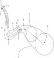
图1A是根据本发明实施例的位于内腔或管道内的材料移除系统的示意图。1A is a schematic illustration of a material removal system within a lumen or conduit, according to an embodiment of the present invention.
图1B是根据本发明实施例的位于内腔或管道内的材料移除系统的立体图。Figure IB is a perspective view of a material removal system within a lumen or conduit in accordance with an embodiment of the present invention.
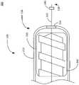
图1C示出了根据本发明实施例的立体图。Figure 1C shows a perspective view according to an embodiment of the present invention.
图1D示出了根据本发明实施例的联接至联接组件的切割组件的锁定机构的立体图。1D illustrates a perspective view of a locking mechanism of a cutting assembly coupled to a coupling assembly in accordance with an embodiment of the present invention.
图2A示出了根据本发明实施例的导丝、切割组件、电机和联接组件的俯视横截面图。2A shows a top cross-sectional view of a guidewire, cutting assembly, motor, and coupling assembly, according to an embodiment of the present invention.
图2B示出了根据本发明实施例的导丝、切割组件、电机和联接组件的俯视横截面图。2B shows a top cross-sectional view of a guidewire, cutting assembly, motor, and coupling assembly, according to an embodiment of the present invention.
图2C示出了根据本发明实施例的切割组件的主视图。Figure 2C shows a front view of a cutting assembly according to an embodiment of the invention.
图2D示出了根据本发明实施例的联接组件的主视图。Figure 2D shows a front view of a coupling assembly according to an embodiment of the present invention.
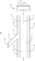
图3A示出了根据本发明实施例的材料移除系统的侧向横截面图,其包括切割工具、导丝、电机和联接组件。3A illustrates a side cross-sectional view of a material removal system including a cutting tool, guide wire, motor, and coupling assembly, according to an embodiment of the present invention.
图3B示出了根据本发明实施例的包括切割工具的材料移除系统的俯视横截面图。3B illustrates a top cross-sectional view of a material removal system including a cutting tool, according to an embodiment of the invention.
图3C示出了根据本发明实施例的包括切割工具的材料移除系统的主视图。Figure 3C shows a front view of a material removal system including a cutting tool in accordance with an embodiment of the present invention.
图4示出了根据本发明实施例的材料移除系统的放大横截面图。Figure 4 shows an enlarged cross-sectional view of a material removal system according to an embodiment of the invention.
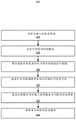
图5是材料移除系统的使用方法流程图。5 is a flowchart of a method of using the material removal system.
具体实施方式detailed description
本发明将通过应与附图结合理解的以下描述得到更全面地理解。在本说明书中,相同标记指代本发明的各实施例中的相似元件。在本说明书中,权利要求是关于实施例来解释的。本领域技术人员将容易理解,本文描述的方法、设备和系统仅是示例性的,并且可以在不背离本发明的精神和范围的情况下进行变化。The present invention will be more fully understood from the following description when read in conjunction with the accompanying drawings. In this specification, like symbols refer to like elements in various embodiments of the invention. In this specification, the claims are interpreted with respect to the embodiments. Those skilled in the art will readily appreciate that the methods, devices and systems described herein are exemplary only and changes may be made without departing from the spirit and scope of the invention.
A.外科手术方案概述A. Surgical Protocol Overview
本文提供的技术涉及改进的材料移除系统,其能够有效且精确地从内腔或管道取出或移除狭窄、瘢痕或肿物。改进的材料移除系统可操纵通过柔性内窥镜或者作为经皮手术的部分并且透视地操纵进入患者的空腔或器官中以切割或切开狭窄、瘢痕或肿物。该改进的材料移除系统可在不必使用另一个抽吸装置或钻孔装置的情况下取回组织的清除样品。Technology provided herein relates to improved material removal systems capable of efficiently and precisely extracting or removing strictures, scars, or masses from lumens or tracts. The improved material removal system is maneuverable through a flexible endoscope or as part of a percutaneous procedure and perspectively into a patient's cavity or organ to cut or dissect strictures, scars or masses. The improved material removal system can retrieve cleared samples of tissue without having to use another suction device or drilling device.
材料移除系统可用于各种应用中。在其他实施例中,材料移除系统可在以下说明书的B部分中进行详细描述。但是,应理解的是,本发明的范围并不限于单一类型的材料移除系统,例如用于胃肠(“GI”)镜或经皮手术,而是扩展到任何类型的柔性切割组件,包括但不限于支气管镜、胃镜、喉镜或可用于治疗患者的其他医疗装置。材料移除系统可治疗身体的各个部位或部分,例如耳朵、食道、胃、小肠、大肠、胰管或其他中空内腔。Material removal systems are used in a variety of applications. In other embodiments, a material removal system can be described in detail in Section B of the description below. However, it should be understood that the scope of the present invention is not limited to a single type of material removal system, such as for gastrointestinal ("GI") endoscopic or percutaneous procedures, but extends to any type of flexible cutting assembly, including But not limited to bronchoscopes, gastroscopes, laryngoscopes, or other medical devices that may be used to treat patients. Material removal systems treat various parts or parts of the body, such as the ear, esophagus, stomach, small intestine, large intestine, pancreatic duct, or other hollow lumens.
B.材料移除系统和方法B. Material Removal Systems and Methods
根据本发明的材料移除系统及其方法可包括多个部件,比如导丝、切割组件和至少一个外部装置。该至少一个外部装置可包括例如电机、泵送装置或显示装置。手持件可联接至部件,操作者可采用该手持件控制部件。作为内窥镜手术的部分或作为涉及经由针刺皮肤而接近器官或其他组织的经皮手术的部分,操作者可将导丝插入腔体。操作者可在内腔或管道内引航导丝以到达材料。操作者可手动推动导丝,或者电机可旋转导丝以操纵该线。操作者可采用透视或内窥镜超声成像方式为该导丝引航。操作者还可采用立体定位机器人辅助导航来引航该导丝。A material removal system and method thereof according to the present invention may include a plurality of components, such as a guide wire, a cutting assembly, and at least one external device. The at least one external device may comprise, for example, a motor, a pumping device or a display device. A handpiece can be coupled to the component with which the operator can control the component. The operator may insert a guidewire into the lumen as part of an endoscopic procedure or as part of a percutaneous procedure involving access to an organ or other tissue via a needle stick in the skin. An operator may navigate a guidewire within the lumen or conduit to reach the material. An operator can manually push the guide wire, or a motor can rotate the guide wire to manipulate the wire. The operator can navigate the guidewire using fluoroscopy or endoscopic ultrasound imaging. The operator can also use stereotaxic robotic assisted navigation to navigate the wire.
在导丝靠近材料后,操作者可沿着导丝将切割组件引导至材料。操作者可沿着导丝操纵该切割组件直至切割组件的锁定机构定位为联接至导丝的联接组件。通过将锁定机构联接至联接组件,操作者或电机可旋转导丝,这将引起导丝使锁定机构旋转,这将引起联接至锁定机构的切割工具切割内腔或管道内的材料。操作者还可使锁定机构与联接组件脱离接合以沿着导丝操纵切割组件。切割组件还可以包括例如使用泵送装置的排出机构(例如冲洗、清洗、传输或将冲洗材料提供到内腔或管道中并且提供至材料的其他特征)。一旦切割工具切割材料,操作者就可以取出材料。切割组件可以连接到泵送装置以取出材料。泵送装置可以联接到手持件或成为手持件的一部分,操作者可以使用该手持件从内腔或管道中抽吸材料。After the guide wire is in proximity to the material, the operator can guide the cutting assembly along the guide wire to the material. The operator can manipulate the cutting assembly along the guidewire until the locking mechanism of the cutting assembly is positioned to couple to the coupling assembly of the guidewire. By coupling the locking mechanism to the coupling assembly, an operator or a motor can rotate the guide wire, which will cause the guide wire to rotate the locking mechanism, which will cause a cutting tool coupled to the locking mechanism to cut material within the lumen or tract. The operator can also disengage the locking mechanism from the coupling assembly to steer the cutting assembly along the guidewire. The cutting assembly may also include an ejection mechanism (eg, flushing, washing, conveying, or other features that provide flushing material into the lumen or conduit and to the material), eg, using a pumping device. Once the cutting tool cuts the material, the operator can remove the material. The cutting assembly can be connected to a pumping device to remove material. The pumping device may be coupled to or be part of a handpiece that an operator may use to pump material from a lumen or conduit.
参见图1A,示出了内腔或管道110和材料移除系统115的示意图100。该内腔或管道110可包括位于一部分内腔或管道110内的材料112。材料移除系统115可包括导丝120和切割组件130。该导丝120可包括联接组件140。切割组件130可包括锁定机构150和切割工具160。该切割工具160可包括一片或多片刀片165。Referring to FIG. 1A , a schematic 100 of a lumen or
例如,进一步参见图1A,为了执行从胆管中移除材料112的手术,可(例如采用超声内镜(EUS))将导丝120引入该胆管。切割组件130可沿着导丝120移至材料112所在的目标位置。导丝120的联接组件140可联接至切割工具160的锁定机构150,并且锁定机构150可驱动该切割工具160以移除材料112。For example, referring further to FIG. 1A , to perform a procedure to remove material 112 from a bile duct, a
该内腔或管道110可为各种类型中的一种,比如为动脉、微动脉、毛细血管、微静脉或静脉。该内腔或管道110还可为软管、导管或凹窝,例如为耳道、鼻道、胆管、肠、食道或胃。示意图100可示出内腔或管道110的一部分。该内腔或管道110的长度可例如为600微米、5厘米、10英寸、100英寸、10米、20米等。内腔或管道110的横截面可例如为1平方毫米至500平方毫米,或者在一些实施例中为2.5平方厘米、10平方厘米、20平方厘米、30平方厘米等。在一些实施例中,示意图100可将内腔或管道110替换或互换为可经由体腔或通过外科手术进入的人体其他部位,例如中空器官、软管、导管、通路或其他凹窝。空腔可以包括例如肠管、窦、内腔、管道或其他天然中空或窦。在一些实施例中,诸如切开手臂或胃创建通往内腔或管道110内的材料112的空腔。在一些实施例中,内腔或管道110可包括材料112。The lumen or
材料112可称作以下其他描述性术语,比如内腔或管道110内的物体、组织或者内容物,并且能够与上述其他描述性术语互换使用。材料112可在内腔或管道110内随时间推移变得明显,以缩窄或者阻挡内腔或管道的路径或开口。例如,由于对内腔或管道110造成损坏或损伤(例如慢性感染)而形成了该材料112。材料112可以是操作者能够从内腔或管道110中移除、取出、检查或收集的液体、固体或液体和固体的组合。内腔或管道110的壁可以接收关于内腔或管道110损坏的指示。狭窄或肿物可以填充或堵住内腔或管道110的损坏部分。内腔或管道110的堵塞物或阻塞物可称作材料112。
在一些实施例中,可采用距离传感器确定材料112的尺寸(例如长度、宽度或高度)。该距离传感器可以测量导丝120横穿经过材料112的距离。在一些实施例中,距离传感器可以测量导丝120横穿经过内腔或管道110的距离。在一些实施例中,材料移除系统115可以基于该距离确定材料112的尺寸。例如,该距离传感器可以测量导丝120穿过材料112的距离。该距离传感器可以基于表示材料112的接触或压力的指示开始测量。导丝120可穿过材料112。一旦导丝120穿过材料,距离传感器不会接收到表示材料的接触或压力的指示,这指示材料112的尽头。该距离传感器可以基于接触材料112和材料112消失之间测得的距离确定材料112的尺寸。在一些实施例中,距离传感器可执行计算,例如在距离测量值的起点和终点之间做减法以确定材料112的尺寸。在一些实施例中,导丝120可包括用于确定材料112的尺寸的相机或观察仪器。In some embodiments, a distance sensor may be used to determine a dimension (eg, length, width, or height) of
导丝120可在内腔或管道110内引航。导丝120操纵进入内腔或管道110。该导丝120可在内腔或管道110内引航以到达材料112。导丝120可由金属、钢、塑料、钛、镍、碳纤维或其他合金中的至少一种构成。导丝120可包括编成,该编成包括至少一种用于插入到内腔或管道110中的化合物,例如聚合物、亲水性材料、镍钛诺、含氟聚合物或两种或多种化合物的组合,以提高导丝120的耐用性、润滑性、柔韧性或耐腐蚀性。该化合物可使该导丝120在被引航的同时还能发光。导丝120对x射线或类似辐射是不透射线的。发出的光允许操作者采用荧光成像技术操纵导丝120。该导丝120可包括一个或多个纹理或凹槽,比如螺旋、扭转、回纹或其他突起或雕刻图案。
导丝120可包括导丝近端124和导丝远端128。导丝120可包括位于导丝远端128处的联接组件140。导丝120可利用导丝远端128插入内腔或管道110中。导丝120可沿着内腔或管道110的路径引航以到达内腔或管道110内的至少一个材料112(即物体、组织等)。内腔或管道110内的材料112可为病变。导丝120可引航经过治疗位置。导丝120可与材料112接触。在一些实施例中,导丝120可构造为引航1、2、3、4、5、6、7、8、9或10毫米进入材料112。在一些实施例中,导丝120可构造为引航1、2、3、4、5、6、7、8、9或10毫米穿过材料112。
导丝120可包括或联接至一个或多个传感器,例如接近传感器、电磁传感器、光学立体定向传感器、相机、光传感器、光源、压力传感器、雷达传感器、流量传感器、弯曲传感器、冲击传感器、距离传感器或用于检查内腔或管道110的其他传感器。一个或多个传感器可例如位于导丝120的导丝远端128上或导丝120内部。传感器可提供用于引航导丝120通过内腔或管道110的数据。在一些实施例中,材料移除系统115可采用一个或多个传感器来确定材料112的位置。在一些实施例中,材料移除系统115可采用一个或多个传感器来检查或研究内腔或管道110内的材料112。例如,可采用驱动装置(未示出)或由操作者手动操纵导丝120穿过内腔或管道110。光源可以包括发光二极管(“LED”)、白炽灯、节能灯、卤素灯、氖灯或其他类型的照明元件。光源可以发光,并且相机可以开始记录。相机可以接收内腔或管道110的各个图像并将图像传输到显示装置(未示出)以显示给操作者。显示装置可以基于接收到的视觉信息生成或显示图像,以供操作者观察内腔或管道110内部。导丝120的相机可以使材料112可视化并且提供材料112的指示。基于导丝120的相机未接收到材料112的指示,可操纵导丝120以穿过材料112。在一些实施例中,导丝120或一个或多个传感器可以接收第二材料112的指示。
传感器可确定内腔或管道110的存在。传感器可确定或检测待移除的材料112的存在。材料移除系统112可使用传感器基于与材料112的接触来识别材料112。例如,导丝120可包括压力传感器。压力传感器可接收关于接触、推动、密度或指示材料112的其他压力信息的指示。类似于先前的示例,导丝120可被操纵进入内腔或管道110并且在内腔或管道110进行引航。导丝120可采用压力传感器接收材料112的压力指示。导丝120可在接收到关于压力指示的同时穿过材料112。导丝120可基于未接收到压力指示而穿过材料。Sensors may determine the presence of lumen or
导丝120可以是出于医疗目的插入内腔或管道110内的柔性线。导丝120可为柔性的,以不会对内腔或管道110或导丝120造成损伤、撕裂、创伤或其他损坏。柔性的导丝120可有助于导丝120在内腔或管道110内引航。例如,内腔或管道110可包括曲线、隆起或其他非线性路径。材料112可位于穿过内腔或管道110内的非线性路径。导丝120可推动、碰撞或冲击内腔或管道110壁以折转经过内腔或管道110的非线性路径。柔性导丝120可在导丝通往材料112的同时降低损坏内腔或管道110的机会。
导丝120可为柔性线圈、引航线、动力线或编织物。导丝120的形状例如为圆柱体、圆锥体或其他棱柱。导丝120可由金属、钢、镍、钛、镍钛诺或其他金属合金中的至少一种构成。导丝120可具有长度。该长度可为10、20、30、40、50、60、70、80、90、100、110、120、130、140、150、160、170、180、190、200、210、220、230、240、250、260、270、280、290、300、310、320、330、340、350、360、370、380、390、400、410、420、430、440、450、460、470、480、490、500、510、520、530、540、550、560、570、580、590、600、610、620、630、640、650、660、670、680、690、700、710、720、730、740、750、760、770、780、790、800、810、820、830、840、850、860、870、880、890、900、910、920、930、940、950、960、970、980、990或1000厘米。导丝120的长度可大于切割组件130的长度。例如,导丝120的长度可为50厘米,切割组件130的长度可为75厘米。导丝120的直径尺寸能够使导丝120插入内腔或管道110中。该直径可为100、200、300、400、500、600、700、800、900或1000纳米。导丝120的直径可允许将导丝120插入切割组件130中以在内腔或管道110内提供通往材料112的路线或引航路径。
导丝120的柔性允许即使在其弯曲部段中也能够保持性能。例如,内腔或管道110壁可弯曲120度。切割组件130(包括位于切割组件130内的部件,比如导丝120)可弯曲120度。弯曲导丝120可在120度弯曲的情况下保持旋转性能。在一些实施例中,护套或衬套包围住导丝120以避免导丝120的外表面和其他表面之间产生摩擦接触。在一些实施例中,聚四氟乙烯(“PFTE”)涂覆导丝120以减小导丝120的外表面和其他表面(比如内腔或管道110的内壁)之间的摩擦接触。在一些实施例中,导丝120的外直径小于其中引航切割组件130的工具通道的直径。例如,在一些实施例中,导丝120的外直径可位于1至4毫米的范围内。在一些实施例中,导丝120的长度超过切割组件130的长度。The flexibility of
导丝120的导丝远端128可包括至少一个传感器以将导丝120引航进入内腔或管道110。该导丝远端128还可包括至少一个传感器以定位材料112。在一些实施例中,操作者引航导丝远端128经过材料112。操作者然后可提供切割组件130以清除材料112。传感器可位于导丝120的导丝远端128。导丝120可包括凹槽或图案比如螺旋、扭转或突起,以有助于切割组件130的运动。在一些实施例中,导丝120还可包括衬套,该衬套围绕导丝120安装以便切割组件130在穿过导丝120时进行操纵。在一些实施例中,衬套可防止空气或其他流体在切割组件130和导丝120之间漏出。The guidewire
在一些实施例中,导丝120可为可伸长线或可回缩线。该导丝120可经由手动操作或者通过电子操作装置伸长或回缩。导丝120可构造为联接至切割组件130,例如联接至切割组件130的锁定机构150。例如,导丝120的导丝近端124可被构造为靠近联接至切割组件130的管远端138。在一些实施例中,导丝120可在长度上伸长以增大导丝近端124和导丝远端128之间的距离。在一些实施例中,导丝120可回缩以减小导丝近端124和导丝远端128之间的距离。例如,导丝120可伸长以操纵导丝远端128穿过材料112。切割组件130可朝向导丝120的导丝远端128操纵。随着切割组件130朝向导丝远端128操纵,导丝120回缩例如以阻止导丝远端128基于切割组件130的运动而运动。In some embodiments, guidewire 120 can be an extendable wire or a retractable wire. The
切割组件130可从导丝近端124穿进内腔或管道110并且穿到导丝远端128以到达材料112。在一些实施例中,切割组件130还可包括围绕导丝120安装的衬套,以使切割组件130通过穿过导丝120在内腔或管道110内操纵。在一些实施例中,衬套可防止空气或其他流体在切割组件130和导丝120之间漏出。Cutting
切割组件130和导丝120可具有类似成分。例如,切割组件130可包括金属、钢、塑料、钛、镍、碳纤维或其他合金。切割组件130可与导丝120成分不同。例如,导丝120可由钢制成,而切割组件130可由金属和塑料制成。切割组件130可被构造为具有更高或更低的密度、更高或更低的展延性、更高或更低的柔性或易于穿过内腔或管道110的其他特征。该切割组件130可为编织衬套。Cutting
切割组件130可包括管远端138和管近端134。管近端134可称作切割组件130的底座、起点或基点。管远端138可称作切割组件130的尖端或前端。在一些实施例中,切割组件130可包括固定至切割组件130的管远端138的导丝120。在一些实施例中,导丝远端128延伸出切割组件130的管近端134。在一些实施例中,导丝远端128通过锁定机构延伸出切割组件130的管远端138。导丝120可伸长或可回缩以增加或减小导丝120的长度。例如,导丝120联接至切割组件130的管远端138。在一些实施例中,导丝120伸长以增加位于管远端138和导丝120的导丝远端128之间的导丝120的长度。在一些实施例中,切割组件130可在导丝120回缩的同时朝向材料112操纵。例如,导丝120随着切割组件130朝向导丝远端128操纵而回缩。Cutting
切割组件130可包括或联接至位于管远端138的一个或多个传感器,例如光传感器、电磁传感器、光学立体定向传感器、压力传感器、冲击传感器、流量传感器、雷达传感器、位置传感器或距离传感器。在一些实施例中,一个或多个传感器可位于切割组件130的不同部位或位置,比如管近端134,或者位于管近端134和管远端138之间。在一些实施例中,切割组件130检测内腔或管道110的存在或检测材料。该切割组件130可配设有至少一个传感器,该传感器能够与至少一个外部装置(比如位于切割组件130外部的传感器处理部件(未示出))通信,以确定材料112的相对于由传感器指示的内腔或管道110的其余位置的厚度。该传感器可以包括例如温度传感器、压力传感器、电阻传感器、冲击传感器、超声传感器或用于医学检查的其他传感器。在一些实施例中,材料112的类型至少与组织的阻抗或密度相关联。传感器可收集温度信息和其他感测信息,并且为传感器处理单元提供对应于此信息的信号。随后,传感器处理单元可识别该材料112的类型。在一些实施例中,传感器可为电传感器。Cutting
在将切割组件130插入内腔或管道110之前可将切割组件130联接到导丝120。切割组件130可被操纵通过空腔,并且从管近端134进入内腔或管道110至管远端138。切割组件130可以使用导丝120穿过内腔或管道110。类似于先前描述的导丝120的示例,切割组件130可以使用压力传感器接收内腔或管道110内的材料112的指示。操作者可以使用切割组件130对材料112(或在内腔或管道110中)执行手术,例如使用例如连接到管近端134的外部装置来取出、检查或收集材料112。Cutting
切割组件130可被操作进入内腔或管道110。类似于导丝120,切割组件130可通过开口或空腔插入。切割组件130可为柔性的切割组件130,从而可转动、弯曲或以其他方式引航通过内腔或管道110的弯曲。类似于导丝120,切割组件130可为柔性的,以不会在内腔或管道110内或者对切割组件130造成损伤、撕裂、创伤或其他损坏。例如,切割组件130操纵进入包括弯曲部分的内腔或管道110。该切割组件130可经由导丝120引航穿过内腔或管道110。导丝120可与内腔或管道110壁接触,从而切割组件130可到达内腔或管道110壁以引航通过内腔或管道110的弯曲部分。切割组件130可到达内腔或管道110的弯曲部分。切割组件130可响应于到达或者与内腔或管道110接触而开始弯曲或转动,从而切割组件130在沿着导丝120引航通过内腔或管道110的同时弯曲穿过内腔或管道110的弯曲部分。Cutting
在一些实施例中,切割组件130可被插入内窥镜或具有器械通道的任意其他医疗装置的器械通道或工作通道。该器械通道可限定出由构造用于切割组件130的附接衬套围出的中空部分或入口。该附接可增大切割组件130的直径、为切割组件130提供另外的形状、纹理、凹槽或其他特征,或者提供用于在内腔或管道110内穿过的壳体。In some embodiments, cutting
切割组件130可沿着导丝120进行操作,例如到达导丝120的导丝近端124。切割组件130可插入内腔或管道110,穿过内腔或管道110,与内腔或管道110接触,到达内腔或管道110内的材料,或使用导丝120以其他方式穿过内腔或管道110。切割组件130可从导丝120的导丝近端124穿至导丝120的导丝远端128。Cutting
导丝120的联接组件140可与切割组件130的锁定机构150联接。在一些实施例中,联接组件140可包括至少一个凹槽、至少一个孔或至少一个凹窝,以联接至锁定机构150的至少一个突出部分或者与其安装在一起。在一些实施例中,联接组件140可包括至少一个突起部分以联接至切割组件130的锁定机构150的至少一个凹槽、凹窝或保持件或者与其联接在一起。联接组件140可包括突起部分和凹窝以与锁定机构150联接在一起。突起部分和凹窝可包括销互连件、磁体、摩擦配合凹槽或其他附接特征。The
联接组件140可联接、链接或连接至切割组件130的锁定机构150。例如,切割组件130可沿着导丝120运动以到达内腔或管道110内的联接组件140。该导丝120可旋转,其使联接组件140旋转,其也将在联接至锁定机构150时旋转。导丝120的旋转可包括例如导丝近端134的旋转或导丝远端128的旋转。联接组件140可响应于导丝远端128的旋转或导丝近端124的旋转而旋转。
联接组件140可位于导丝远端128。该联接组件140距离导丝远端128有一定距离。该联接组件140与导丝远端128的距离可容纳内腔或管道110内材料112的尺寸和长度。该距离可为1、2、3、4、5、6、7、8、9、10、11、12、13、14、15、16、17、18、19、20、21、22、23、24、25、26、27、28、29、30、31、32、33、34、35、36、37、38、39、40、41、42、43、44、45、46、47、48、49、50、51、52、53、54、55、56、57、58、59、60、61、62、63、64、65、66、67、68、69、70、71、72、73、74、75、76、77、78、79、80、81、82、83、84、85、86、87、88、89、90、91、92、93、94、95、96、97、98、99、100厘米。在一些实施例中,联接组件140重新布置在导丝120的不同位置。例如,联接组件140联接至距导丝120的导丝远端128的1厘米处。内腔或管道110内的材料112可具有长度。该长度可为1、2、3、4、5、6、7、8、9、10、11、12、13、14、15、16、17、18、19、20、21、22、23、24、25、26、27、28、29、30、31、32、33、34、35、36、37、38、39、40、41、42、43、44、45、46、47、48、49、50、51、52、53、54、55、56、57、58、59、60、61、62、63、64、65、66、67、68、69、70、71、72、73、74、75、76、77、78、79、80、81、82、83、84、85、86、87、88、89、90、91、92、93、94、95、96、97、98、99或100毫米。该导丝120可穿过材料112的第一侧到达材料112的第二侧。例如,材料112可将联接组件140从距离导丝远端128的1厘米的位置推动到距离导丝远端128的10厘米的位置。A
构成联接组件140由类似于例如导丝120、切割组件130、切割工具160或锁定机构150的材料构成。联接组件140位于导丝120的包括例如位于导丝远端128处或距导丝远端128一定距离的部分。距导丝远端128的距离可例如包括至少1毫米、5厘米、10厘米或距导丝远端128为2英寸。联接组件140可与内腔或管道110内的材料112接触。该联接组件140可距离材料112一定距离。该距离可为1、2、3、4、5、6、7、8、9、10、11、12、13、14、15、16、17、18、19、20、21、22、23、24、25、26、27、28、29、30、31、32、33、34、35、36、37、38,39、40、41、42、43、44、45、46、47、48、49、50、51、52、53、54、55、56、57、58、59、60、61、62、63,64、65、66、67、68、69、70、71、72、73、74、75、76、77、78、79、80、81、82、83、84、85、86、87、88,89、90、91、92、93、94、95、96、97、98、99或100毫米。联接组件140的尺寸类似于锁定机构150。例如,联接组件140和锁定机构150的直径均为0.5、1、2、3、4、5、6、7、8、9或10毫米。联接组件140可包括与锁定机构150对置的中空部分或突起部分。突起部分的中空部分可包括与锁定机构150类似的形状,比如十字形、方形、三角形或其他几何形状。例如,如果锁定机构150包括十字形中空部分,联接组件140可包括构造成与锁定机构150联接的十字形突起部分。
联接组件140可包括或联接至第二电机。在一些实施例中,联接组件140可包括或联接至第二电机。该联接组件140可响应于接收信号而开始旋转。因此,导丝120、切割工具160、锁定机构150或导丝近端124和导丝远端128之间的任意部分可以与等效旋转或扭矩串接地或同步地旋转。The
锁定机构150可包括用于与联接组件140联接的孔、路径、间隙或中空区域。该导丝120经由锁定机构150的中空区域从管远端134至管远端138穿过锁定机构150。在一些实施例中,锁定机构150可包括位于锁定机构150的一部分上的突起,该突起例如位于锁定机构的中心位置、边缘或中心位置和边缘之间。
该锁定机构150可位于切割工具160的中心或中间。在一些实施例中,锁定机构150可包围导丝120,导丝例如穿过锁定机构150的中空部分。切割组件130可通过内腔或管道110穿过由锁定机构150包围的导线120。锁定机构150可包括至少一个中空区域,比如中心、边缘或中心和边缘之间。锁定机构150的中空部分可为各种形状,比如十字形、矩形、正方形、圆形、三角形或其他几何形状。锁定机构150可以包括厚度。厚度可以是1、2、3、4、5、6、7、8、9或10毫米。锁定机构150可以包括区域。该区域可为1、2、3、4、5、6、7、8、9或10平方毫米。切割组件130可包括突出部分。突出部可以从锁定机构150突出一段距离。该距离可以是100纳米、500纳米、1毫米。该距离也可以是2、3、4、5、6、7、8、9或10毫米。在一些实施例中,锁定机构150可以包括至少一个中空部分和至少一个突出部分以促进与联接组件140接合。The
切割组件130的锁定机构150可沿着导丝120操纵或被操纵至联接组件140。该切割组件130可到达或定位到联接组件140附近,比如距离联接组件140为1毫米、1厘米或1英寸。响应于或随后接近联接组件140,锁定机构150可朝向联接组件定位或拉动。锁定机构150可响应于与联接组件140的接触而联接至或附接至联接组件140。The
具体参见图1C和1D,示出了关于联接至联接组件140的锁定机构的说明。切割组件130可通过沿着导丝120朝向导丝远端128运动而从图1C转换到图1D。在一些实施例中,联接组件140被定位在与导丝120的导丝远端128一定距离处。例如,如图1C所示,切割组件130可采用锁定机构150与距导丝远端128一定距离的联接组件140联接。例如通过操作者将切割组件手动插入内腔或管道110内或通过构造为沿着导丝120操纵切割组件130的电力运行装置,切割组件130可朝向联接组件140操纵。在一些实施例中,操作者可沿着导丝120推动、驱动或移动该切割组件130。如图1D所示,切割组件130可联接至联接组件140或与联接组件140锁定在一起。切割组件130可接收关于附接至联接组件140的指示。切割组件130可为连接到切割组件130的至少一个外部装置提供该指示,该外部装置例如为显示装置、音频装置、手持件或其他信号装置。在一些实施例中,联接组件140可以是用于将切割组件130和导丝120联接的中间部件。Referring specifically to Figures 1C and ID, an illustration of the locking mechanism coupled to the
锁定机构150可通过至少一种联接技术与联接组件140联接,该联接技术比如为摩擦配合、销互连、扭矩配合、旋转联接、卡环、销互连、磁体、摩擦配合槽或互锁或将多个部件连接在一起的其他联接或紧固技术。锁定机构150的突起可与联接组件140联接。在一些实施例中,锁定机构150可包括至少一个中空部分和至少一个突起部分以与联接组件140联接。例如,切割组件130可采用导丝120穿过内腔或管道110。切割组件130可到达位于一部分导丝120处比如导丝远端128处的联接组件140。切割组件130可采用与切割工具160接触的锁定机构150联接至联接组件140。在一些实施例中,联接组件140和锁定机构150可包括构造为在两个部件之间联接的中空部分或突起部分。例如,联接组件140可包括与锁定机构150对置的突起部分或中空部分,比如以实现摩擦配合、销互连、扭转锁定或其他连接特征。The
磁力也能将联接组件140联接至锁定机构150。在一些实施例中,联接组件140和锁定机构150可由磁性材料或铁磁材料构成以在两个部件之间提供磁吸力。铁磁材料可为铁、镍或钴。锁定机构150可附接至、拉入或者朝向由至少一种铁磁材料构成的联接组件拉动。在一些实施例中,锁定机构150可由铁磁材料构成,联接组件140可由磁性材料构成。当锁定机构150位于联接组件140的范围内时,切割组件130可拉至联接组件140。该范围表示锁定机构150磁性联接至联接组件140的距离,比如1、2、3、4、5、6、7、8、9或10厘米。Magnetic force can also couple
切割工具160可从内腔或管道110切除材料112。穿过内腔或管道的切割组件130能够用切割工具160切割、移除、刮除或清除材料112。在一些实施例中,切割工具160从内腔或管道110清除或切割材料112。切割工具160可将材料112切成足够小的块,切割组件130可取出该块使得在无需将切割组件130从内腔或管道110移除的情况下切割组件130收集已清除的材料112。在一些实施例中,响应于将材料112清除成清除材料的切割工具160,切割组件130可从内腔或管道110吸入、拿出或泵出清除材料112。清除材料112可被收集入凹槽并且从切割工具160的远端向下穿到切割工具160的近端以收集清除材料112。切割工具160可将清除材料从切割组件130的管远端138抽出至管近端134。Cutting
切割工具160可采用刻在切割工具160内的凹槽或凹窝从内腔或管道110捕获或收集清除材料112。清除可包括涉及从内腔或管道110分离出材料112或一部分材料112的任意动作。因此,包括但不限于以下动作也是清除的示例:完全或部分地取出、切开、切割、切碎、切片、粉碎。在一些实施例中,切割工具160手动操作或者可采用清除材料112的任何其他方式,使得切割工具160例如通过下文描述的抽吸通道222从内腔或管道110取回已清除的材料112。切割工具160能以多种速度旋转以切割材料112,该速度例如为1000转每分钟(“RPM”)、5000RPM、10000RPM、20000RPM、30000RPM、40000RPM或50000RPM。Cutting
切割工具160可以包括剪刀、刀片、锯或任何其他锋利的工具。切割工具160可以包括切割、切开或取出机构中的至少一种类型,例如风扇、轴向刀具、钻头、钩子、扩孔锥、铣刀或其他切割工具或装置。切割工具160可包括从切割工具160的远端穿到切割工具160的近端的螺旋凹槽,其被构造为沿着螺旋凹槽使清除材料112穿过。切割工具160可由一种或多种材料制成,比如钢、塑料、碳纤维、钛、铝、金属或用于切割材料112的其他合金。在一些实施例中,切割工具160包括不透射线的切割尖端。Cutting
切割工具160可联接至或靠近切割组件130的管远端138。切割工具160可包括近端和远端,近端位于与导丝近端124类似的位置,远端位于管远端134或切割组件130的尖端。切割工具160可包括长度。在一些实施例中,该长度类似于切割组件130。在一些实施例中,长度为1、2、3、4、5、6、7、8、9、10、11、12、13、14、15、16、17、18、19、20、21、22、23、24、25、26、27、28、29、30、31、32、33、34、35、36、37、38、39、40、41、42、43、44、45、46、47、48、49、50、51、52、53、54、55、56、57、58、59、60、61、62、63、64、65、66、67、68、69、70、71、72、73、74、75、76、77、78、79、80、81、82、83、84、85、86、87、88、89、90、91、92、93、94、95、96、97、98、99或100厘米。A
现参见图1C,切割工具160可包括风扇叶片165a-c(统称为风扇叶片165)。风扇叶片165可以由一种或多种用于切割或切开材料112的材料组成,该材料例如为金属、钛、铝或合金。切割工具160可以包括一片或多片刀片,例如图1C所示的三片刀片。在一些实施例中,切割工具160包括1、2、3、4、5、6、7、8、9、10、20、30、40、50、60、70、80、90或100片风扇叶片165。Referring now to FIG. 1C , cutting
切割工具160还可在外套管210的一侧露出,例如在如图3A所示的切割窗口310处,以相对于导丝120或切割组件130的运动切向或侧向切割。切割工具160联接到切割组件130的外套管210,例如外套管210内的凹槽,以旋转切割工具160。在一些实施例中,切割工具160可以距内套管220一定距离,例如与内套管220相距1毫米、2毫米或3毫米。在一些实施例中,切割组件130不包括内套管220,而仅包括被外套管210包围的切割工具160。切割工具160可以包括锁定机构150。Cutting
在锁定机构150联接到联接组件140之后,切割工具160可以旋转。切割工具160可以包括锁定机构150。切割工具160可以与锁定机构150一起旋转。切割工具160可以例如通过包括线性致动器执行轴向切割,该线性致动器与导丝120联接以响应于导丝120的旋转沿着切割组件130的轴线被驱动。在一些实施例中,切割工具160可以被手动致动,使得切割工具160可以通过机械力的转换运行,该机械力由操作者施加或者使用涡轮机、电机230或任何其他用于致动切割工具160的力产生部件来自动地致动。After the
参见图2A-D,材料移除系统200可包括导丝120、切割组件130、电机230和泵送装置240。材料移除系统200可为图1中示出的材料移除系统115。切割组件130包括切割工具160、锁定机构150、外套管210、内套管220、抽吸通道222和冲洗通道225。在一些实施例中,外套管210可选择性地包括凹窝215。在一些实施例中,未示出的手持件可联接至导丝120、切割组件130、电机230和泵送装置240。操作者可采用手持件来控制导丝120、切割组件130、电机230、泵送装置240或任意其他外部装置。在一些实施例中,手持件可被构造为同步控制多个部件,使得在泵送装置250提供抽吸和冲洗实体的同时切割工具正在旋转。在一些实施例中,手持件可单独控制每个部件,比如仅开始旋转电机230或仅采用泵送装置240开始抽吸。Referring to FIGS. 2A-D ,
外套管210可为切割组件130的壳体、外管、外壳或主体。外套管210可包围切割组件130的管远端138或尖端。外套管210在切割组件130的管远端138处可包括开口,比如切割窗口310。外套管210的一部分径向壁可限定出围绕外套管210的一部分半径延伸的开口。在一些实施例中,操作者可从切割材料112接收或取回清除材料。
外套管210的形状可被设计为或成型为例如圆柱体、棱柱、锥体或其他形状。外套管210可为柔性的。外套管210可以被折弯或弯曲至任何度数。在一些实施例中,外套管210可被折弯和弯曲至10、20、30、40、50、60、70、80、90、100、110、120、130、140、150、160、170或180度。外套管210可包括厚度。该厚度可为10纳米、20纳米、1毫米、2毫米、3毫米、4毫米或5毫米。外套管210可以包括宽度。宽度可以是1毫米、2毫米、3毫米、4毫米、5毫米或1厘米。外套管210可以包括长度。长度可以是1米、2米、3米、4米、5米、6米、7米、8米、9米、10米、50米、100米等。外套管210可以包括横截面积,例如0.6平方毫米、1平方毫米、1.9平方毫米等。外套管210可由比如金属、钢、塑料、橡胶、玻璃、碳纤维、钛、铝或其他合金的材料制成。The
内套管220可例如通过采用包括在外套管210内或位于内套管220上的凹槽、凹窝或螺栓相对于外套管210旋转。现参见图2B,外套管210可选择性地包括将切割工具160联接至外套管210的凹窝215。切割工具160可独立于外套管210旋转。例如,电机230可致动导丝120旋转,以对联接至切割工具160的联接组件140施加旋转。切割工具160可在外套管210的凹窝215内旋转。凹窝215可便于将切割工具160定位在切割组件130内,使得在旋转过程中切割工具160不会与切割组件130的管远端138分开或分离。
返回参见图2A-D,外套管210可至少部分围绕内套管220。在一些实施例中,内套管220切除掉抽吸入或以其他方式进入管远端138的开口的任何材料。内套管220可包括位于切割组件130的管远端138处的开口,使得由切割工具160切除的材料经由管远端138处的开口进入。内套管220的管远端138可包括切割部段,而内套管220的导丝近端124可为敞开的,使得通过切割部段进入内套管220的管远端138的材料112可穿过内套管220的导丝近端124。在一些实施例,导丝120附接至内套管220,以引起内套管220随着切割工具160沿着内套管220的纵轴线旋转。如果外套管210未附接至内套管220或导丝120,内套管220可相对于外套管210旋转。在一些实施例中,内套管220可沿着基本纵向的轴线相对于外套管210旋转,这在旋转过程中为内套管220提供了更多的稳定性。Referring back to FIGS. 2A-D , the
内套管220的长度类似于或小于外套管210。该长度可为1、2、3、4、5、6、7、8、9、10、11、12、13、14、15、16、17、18、19、20、21、22、23、24、25、26、27、28、29、30、31、32、33、34、35、36、37、38、39、40、41、42、43、44、45、46,47、48、49、50、51、52、53、54、55、56、57、58、59、60、61、62、63、64、65、66、67、68、69、70、71、72、73、74、75、76、77、78、79、80、81、82、83、84、85、86、87、88、89、90、91、92、93、94、95、96、97、98、99或100厘米。内套管220可设计为便于清除一个或多个材料112并且移除在单个手术中相关联的清除材料112。内套管220可被布置在外套管210内。内套管220可与切割组件130的外套管210联接。内套管220可由与外套管210相类似的材料构成。类似于外套管210,内套管220可以是柔性的。The length of the
内套管220可联接至至少一个外部装置,比如泵送装置240。内套管220可提供采用泵送装置240将包括材料112的一个或多个实体抽出、牵引或拖拽远离内腔或管道110的路径。例如,操作者可将切割组件130插入内腔或管道110中。切割组件130可采用导丝120操纵至材料112。切割组件130可采用泵为内腔或管道110提供或推进冲洗材料,比如水或空气。切割组件130可采用泵送装置240抽出、收集或接收一部分材料112(或清除材料112)。收集的材料112可通过内套管220转移至外部收集装置(未示出)以供检查或收集。在一些实施例中,内套管220是与切割组件130或外套管210分开的部件。The
在一些实施例中,内套管220可以配备有可注射染料组分,操作者可以利用该可注射染料组分在透视引导下确定狭窄的程度或标记内腔或管道110内的特定区域。在其他实施例中,操作者可以用切割工具160标记特定区域,无需使用可注射染料。In some embodiments, the
在一些实施例中,内套管220可包括多个管,比如第一内套管和第二内套管。第一内套管可联接有或连接至第一泵送装置。第二内套管可联接有或连接至第二泵送装置。第一泵送装置可连接至包括冲洗材料比如化合物或气体的容器。第一泵送装置可将冲洗材料排入内腔或管道110。第二泵连接至收集装置,比如不同的容器。第二泵送装置可将材料112从内腔或管道110取出、抽出或收集到不同的容器中以存储。例如,操作者可将切割组件130沿着导丝120引导至内腔或管道110内的材料112。切割组件130可联接至联接组件140。电机230可使导丝120开始旋转。联接组件140可响应于电机230的旋转而开始旋转。切割组件160可随着联接组件140旋转以清除内腔或管道110内的材料112。第一内套管可提供空气和水以采用第一泵送装置辅助切割工具160的清除过程。第二内套管可采用第二泵送装置从内腔或管道110取出清除材料112。在一些实施例中,第一泵送装置和第二泵送装置可同步地或同时地提供冲洗材料和取出材料112。In some embodiments,
内套管220可为中空的,使得内套管220的内壁可限定出至少一部分抽吸通道222。在一些实施例中,导丝120的外壁可被构造为限定出抽吸通道222的另一部分,该抽吸通道的另一部分流体联接至抽吸通道222的由切割组件130的内套管220的内壁限定出的部分。在一些实施例中,内套管220可包括衬套,导丝120位于该衬套内。在一些实施例中,包围导丝120的衬套还限定出抽吸通道222。该衬套可以是导丝120和抽吸通道222之间的屏障。因此,通过防止空气通过导丝120或内套管220逸出或进入,衬套可允许抽吸通道222在抽吸通道222的长度上保持抽吸力。The
抽吸通道222可延伸经过切割组件130的长度。抽吸通道222的位于切割组件130的管远端138处的近端可接收抽吸力。抽吸力引起至少一个材料112引入外套管210的靠近抽吸通道222远端的开口内,该材料然后可被切割组件130的内套管220切割。抽吸力可从内腔或管道110抽吸、取出、吸入或以其他方式取回位于抽吸通道222远端处的材料,并且抽出材料112经过抽吸通道222到达抽吸通道222的近端。由此,可部分基于由外套管210的内周限定的抽吸通道222的尺寸确定位于管远端138处的开口尺寸。
内套管220和外套管210具有间隔、区域或间隙。在一些实施例中,该间隔包括例如为0.1、0.2、0.3、0.4、0.5、0.6、0.7、0.8、0.9、1.0、2、3、4或5毫米的间隙。在一些实施例中。外套管210可例如经由位于外套管210的管远端138处的外套管210的凹槽联接至切割工具160。在一些实施例中,内套管220可位于外套管210和切割工具160之间,使得内套管220包围切割工具160。在一些实施例中,内套管220可围绕内套管220的纵轴线并且相对于外套管210旋转。例如,独立于并且相对于外套管210,导丝120可经由联接至锁定机构150的联接组件140旋转而引起内套管220旋转。外套管210和内套管220之间的间隔可限定出冲洗通道225。
冲洗通道225可为内腔或管道110提供冲洗材料。在一些实施例中,冲洗通道225可为抽吸通道222提供冲洗材料。冲洗材料能够存储在位于切割组件130的外部或内部的贮存室或容器(未示出)中。在一些实施例中,切割组件130可通过开口接收冲洗材料,如在图4中更加详细的描述。外部装置比如泵送装置240可推动材料经过冲洗通道225。操作者可将冲洗材料应用至内腔或管道110。操作者可应用冲洗材料以疏通位于内腔或管道110内的开口(例如阻塞内腔或管道110的损坏部分)。操作者可应用冲洗材料以为内腔或管道110提供药膏或其他药物,从而促进内腔或管道110的损坏部分的愈合过程。在另一个示例中,操作者可至少将液体或气体泵送入冲洗通道225以促进对位于内腔或管道110内的材料112进行清除处理。
切割组件130可限定出冲洗通道225。在一些实施例中,外套管210的内壁可限定出冲洗通道225。在一些实施例中,内套管220的外壁可限定出冲洗通道225。在一些实施例中,内套管220的外壁和外套管210的内壁可限定出一部分冲洗通道225。在一些实施例中,冲洗通道225可从冲洗入口延伸至外套管210的例如位于管远端138处的开口。在一些实施例中,内套管220的内壁可用于防止穿过抽吸通道222的任何材料112穿过壁逃离。在一些实施例中,内套管220的外壁可防止冲洗材料穿过冲洗通道225通过内套管220的壁流入抽吸通道222。在一些实施例中,冲洗通道225具有与抽吸通道222所描述的类似功能,比如用于抽吸材料112。Cutting
材料移除系统200的电机230可联接至导丝120以使导丝120旋转。电机230可为导丝120提供旋转、扭矩或信号。电机230可为导丝120的导丝近端124提供旋转。联接组件140可接收从导丝120的导丝近端124穿过到达导丝远端128的扭矩。锁定机构150可从联接组件140处接收旋转力。例如,当电机230(即由操作者手动或电动地供能)对导丝120开启或施加旋转时,锁定机构150可从联接组件140处接收旋转力。
电机230可通过旋转导丝120使联接组件140旋转。导丝120可将在导丝近端处接收到的扭矩传递至联接组件140,联接组件进一步将扭矩传递至切割组件130的锁定机构150以引起切割组件130的切割工具160旋转。电机230可使导丝120开始旋转。作为回应,联接组件140可随后旋转。例如,电机230可使导丝120开始旋转30度。作为回应,联接组件140可旋转30度。在一些实施例中,电机230可使导丝120的导丝近端124开始旋转。提供给导丝120的导丝近端124的扭矩会引起导丝远端128旋转。响应于或紧接着电机230开始的旋转,联接组件140可在导丝120的导丝远端128处或距该导丝远端一定距离处旋转。例如,电机230可使导丝120的导丝近端124开始旋转60度。提供至导丝120的导丝近端124的扭矩会引起导丝远端128对应旋转60度。响应于或紧接着电机230开始的旋转,联接组件140可在导丝120的导丝远端128处或距导丝远端一定距离处提供60度旋转。
电机230可通过导丝120向联接组件140传送包括旋转或扭矩信息的信号。导丝120可类似于构造为传送或接收信号的线缆或线。联接组件140可包括构造为接收用于开始旋转的信号的控制器。该联接组件140可接收由电机230提供的表示旋转、扭矩或其他信息的信号。例如,操作者可手动或致动该电机230以向联接件传送施加90度旋转的信号。电机230可发出传送至联接组件140的信号。类似于电机230,联接组件140可响应于接收到的信号施加90度的旋转。The
电机230和联接组件140的等效旋转可以提供与切割工具160的使用相关的改善的精度、切削精度、控制性和功耗。联接组件140的旋转匹配电机230的旋转可以通过从导丝近端124到导丝远端128提供均匀分布的动力、旋转或扭矩来促进控制切割工具160。在联接组件140未固定至导丝120的情况下,切割工具160可旋转或提供大于或小于电机230的扭矩,这会引入更小的精度并且需要更多的能耗以旋转特定角度。例如,在导丝120的导丝近端124和导丝远端128之间未等效旋转的情况下,电机230可旋转30度,位于导丝远端128处的切割工具160可旋转15度。在一些实施例中,导丝近端124处和导丝远端128处之间的旋转差异与导丝120和切割组件130的长度有关。在此实施例中,作为一个示例,电机230可为管近端134提供90度旋转,并且如果切割工具位于距离管近端134为5米,切割工具可开始旋转60度。在另一个示例中,如果切割工具160位于距离管近端134为10米,由电机230施加的90度旋转可转换成切割工具160的30度旋转。The equivalent rotation of the
电机230可向导丝120供应电流。电机230可向导丝120的导丝近端124供应电流。导丝120中的电流可为导丝120中的传感器供能。在一些实施例中,穿过切割组件的管或通道的单独导管可携载电线以为导丝120提供能量。来自电源的电流可使联接组件140磁化。联接组件140将与切割组件130的锁定机构150联接至磁化的导丝120。在一些实施例中,锁定机构150和联接组件140形成了电连接,以使导丝120中的电流流动至联接组件140和锁定机构150。在一些实施例中,响应于阻断来自电机230的电能,磁场终止,从而终止流向由磁性材料构成的导丝120的电流。当导丝120消磁时,联接组件140将与切割组件130的锁定机构150分离。The
电机230可向切割组件130供应电流。电机230可向切割组件130的管近端134供应电流。在一些实施例中,切割组件130经由锁定机构150从导丝120处接收电流。切割组件130中的电流可向切割组件130供能。在一些实施例中,切割组件130中的电流可向切割工具160供能。在一些实施例中,切割组件130中的电流可向切割组件130中的传感器供能。在一些实施例中,电机230沿着导丝120推动、驱动或移动切割组件130。电机230可位于切割组件130的外部。
操作者可手动或电动地操作电机230。在一些实施例中,手持件可包括可调阀以控制由电机230施加的能量值。电机230可连接至电源,其被构造用于接收电能。电机230可为液压的、气动的、电动的或压电的。电机230的部件可例如包括转子、轴承、定子和电机控制器。在一些实施例中,电机230为材料移除系统200的部分,从而材料移除系统200是一种独立式装置、工具或部件。在一些实施例中,电机230可采用交流电(“AC”)或直流电(“DC”)运行。电机230可将电能转换为机械能以启动电机230内的至少一个部件或机构。在一些实施例中,电机230的致动自动地致动泵送装置240以取出已切除的材料112。An operator may manually or electrically operate the
泵送装置240可从内腔或管道110取回、取出或收集清除材料112。泵送装置240可经由抽吸通道222从内腔或管道110抽出、吸出或拽出材料112。泵送装置240开启抽吸特征或抽吸力以在管远端138处从内腔或管道110取出清除材料112或冲洗材料,使冲洗材料穿过抽吸通道222到达管近端134。泵送装置240还可在内腔或管道110内套管220抽出液体、流体或气体。例如,切割组件130可到达材料112并且开始清除过程以将来自内腔或管道110的材料112切割或切成小块或清除材料112。泵送装置240可响应于清除材料112而启动。因此,清除材料112可被抽吸、吸出或抽入切割组件130的内套管220中以取回或取出材料112。在一些实施例中,泵送装置240可包括收集盒或收集舱,其用于存储采用泵送装置240从内腔或管道110取出的清除材料、切割材料或冲洗材料。在一些实施例中,收集盒流体联接至抽吸通道222的近端。
在一些实施例中,泵送装置240可通过第一内套管向内腔或管道110提供冲洗材料,并且通过第二内套管从内腔或管道110取出至少一种材料112。在一些实施例中,切割组件130不包括泵送装置240。另外,泵送装置240可构造为提供冲洗材料或朝向材料112将其提供进内腔或管道110。In some embodiments,
泵送装置240可推动、提供、传送或引入一种或多种材料进入内腔或管道110。例如,泵送装置240可将气体、液体或其他化合物提供到内腔或管道110中。所提供的材料可有助于材料112的清除过程。提供的材料还可为内腔或管道110的损坏部分提供治疗方案。例如,内腔或管道110壁可包括狭窄部分。泵送装置240可提供涂层材料或化合物以遮住、覆盖或修护该狭窄部分。泵送装置240可从存储室中抽出该冲洗材料并且将该冲洗材料推入内腔或管道110。在一些实施例中,可包括两个泵送装置,例如一个用于经由抽吸通道222进行抽吸,一个用于经由冲洗通道225提供材料。The
泵送装置240可经由导丝120提供冲洗材料。在一些实施例中,导丝近端124可连接至构造用于提供冲洗材料的泵送装置240。导丝120可包括递送通道(未示出),其构造为在导丝近端124处接收冲洗材料,并在导丝远端128处释放冲洗材料。冲洗材料可冲洗内腔或管道110。在一些实施例中,由于导丝120在内腔或管道110内引航至材料112,冲洗材料可冲洗材料112。
泵送装置240可经由冲洗通道225提供冲洗材料。泵送装置240可控制冲洗材料流经切割组件130的冲洗通道225。在一些实施例中,泵送装置240可提供推动特征,以经由切割组件130推动、传送或以其他方式将冲洗材料提供至内腔或管道110中。泵送装置240可经由冲洗通道225提供冲洗材料。泵送装置240可联接至切割组件130的管近端134。在一些实施例中,泵送装置240可经由管近端134连接至抽吸通道222。泵送装置240可连接至切割组件130的冲洗通道225。泵送装置240可包括多个部件。多个部件可例如包括外壳、叶轮、背板、轴和轴密封件。泵送装置240可位于切割组件130的外部。操作者可通过信号或机械触发启动泵送装置240。在一些实施例中,手持件可包括可调阀,以控制由泵送装置240供给的抽吸的冲洗量。
参见图3A-C,示出了材料移除系统300,具有带有切割窗口310的切割组件130的各个视图。除了图1和2的描述和示例之外,以下说明详细描述了材料移除系统300。Referring to FIGS. 3A-C , a
切割窗口310可接收内腔或管道110内的材料112。该切割窗口310可定位在外套管219的一侧。相对于导丝120或切割组件130的运动,切割窗口310能够切向或侧向切割材料112。在一些实施例中,外套管210可包括切割窗口310。切割窗口310可包括用于露出切割工具160的中空结构,该真空结构的形状比如呈圆形、椭圆形、矩形或其他几何形状。切割窗口310可包括直径。该直径可为1毫米、2毫米、3毫米、4毫米或5毫米。切割窗口310可包括挖空,其可为切割组件130的一部分。例如,切割窗口310可包括0.4毫米的挖空。Cutting
切割窗口310可被构造为使切割工具160经由切割窗口310能切割、切开或清除内腔或管道110内的材料112。例如,切割组件130联接至联接组件140。电机230可以使导丝120开始旋转。联接组件140的旋转可等效于电机230或导丝近端124的旋转。固定至锁定机构150的切割工具160可随着联接组件140旋转以开始清除过程。例如,切割组件130可通过旋转切割工具160穿过材料112以在切割组件130的切割窗口310中接收材料112而开始清除或切割过程。切割组件130可经由切割窗口310接收材料112的一个或多个部分,并且采用切割工具160来清除材料112。泵送装置240可通过内套管220从内腔或管道110抽吸或抽出清除材料112。Cutting
参见图4,示出了材料移除系统400的放大横截面视图。除了图1-3的描述和示例之外,以下说明详细描述了材料移除系统400。该横截面视图可说明切割组件130的一部分。具体地,切割组件130可包括具有连接件近端414和连接件远端418的灌洗连接件410。Referring to FIG. 4 , an enlarged cross-sectional view of a
灌洗连接件410可以是用于向切割组件130提供冲洗材料的管状件。内套管220的外壁和外套管210的内壁之间的间隙可限定出冲洗通道225的一部分。冲洗材料可流经灌洗连接件410自连接件近端414至连接件远端418的的部分并朝向切割工具160通过冲洗通道225部分。来自冲洗通道225的冲洗材料随后可散布或将冲洗材料至内腔或管道110中。冲洗材料可冲洗该材料112。内套管220可限定出抽吸通道222的一部分,剪掉或切除的材料以及冲洗材料通过该抽吸通道的一部分可从切割工具160流向切割组件130的管近端134。
灌洗连接件410可以是从外套管210起与管远端138成一定角度地延伸的Y端口。该角度可为5、10、15、20、25、30、35、40、45、50、55、60、65、70、75、80、85、90、95、100、105、110、115、120、125、130、135、140、145、150、155、160、165、170、175或180度。在一些实施例中,灌洗连接件410可位于切割组件130的插入内腔或管道110的部分的外部。在一些实施例中,外套管210可从灌洗连接件410的连接件远端418延伸至切割组件130的管近端134,其可位于内腔或管道110的外部。在一些实施例中,灌洗连接件410可为切割组件130的分离部件,从而灌洗连接件410不会随着电机230致动导丝120旋转而旋转。该灌洗连接件410可为外部冲洗材料进入冲洗通道225提供稳定的开口。
灌洗连接件410的连接件近端414可将灌洗连接件410联接至外套管210的开口。该灌洗连接件410可在连接件近端414处与外套管210的内壁联接。在一些实施例中,灌洗连接件410的连接件远端418可按压配合入切割组件130的外套管210的管近端134。在一些实施例中,灌洗连接件410的连接件近端414可连接至切割组件130的管近端134。Connector
灌洗连接件410的连接件远端418可以是构造为接收流入冲洗通道225的冲洗材料的冲洗进入端口。该连接件远端418可从外部贮存室或容器接收冲洗材料。灌洗连接件410的连接件远端418可连接至泵送装置240以接收并且推动冲洗材料通过冲洗通道225。连接至灌洗连接件410的泵送装置240可不同于连接至抽吸通道222并且构造成抽吸材料112的泵送装置。Connection
参见图5,示出了本文描述的材料移除系统115、材料移除系统200、材料移除系统300或材料移除系统400的使用方法500。本文描述的部件的各个实施例可执行方法500。在内腔或管道的内部和外部均可重复该方法500或其步骤,例如以处理待移除的多个材料。Referring to FIG. 5 , there is shown a method 500 of using
在510处,导丝(例如导丝120)操纵进入内腔或管道(例如内腔或管道110)。在一些实施例中,导丝作为包括用于诊断和治疗的一个或多个步骤的外科手术的部分,操作者可例如通过收集至少一个样品、移除至少一个材料(例如材料112)或拓宽狭窄的腔道来插入导丝。操作者可以通过识别体腔例如窦道、内腔或其他天然中空或窦来引入空腔。导丝可通过该空腔操纵进入内腔或管道。该空腔可为体腔或身体内部的空间,比如口、耳、鼻、食道、胰管或结肠。至少一种外科手术,例如经皮手术、切割、钻孔或切开可以形成空腔。形成的空腔可以位于各个不同部位,例如手臂、胃、肝脏、颈部或肾脏。在一些实施例中,操纵导丝是经皮手术的部分,其涉及经由皮肤的针刺进入器官或其他组织。该导丝还可操纵通过内窥镜的工作通道。在一个示例中,导丝从切割组件的管近端操纵至切割组件的管远端。该导丝可操纵通过锁定机构的中空部分。At 510, a guidewire (eg, guidewire 120) is steered into a lumen or tract (eg, lumen or duct 110). In some embodiments, the guidewire is used as part of a surgical procedure that includes one or more steps for diagnosis and treatment, and the operator can, for example, collect at least one sample, remove at least one material (eg, material 112 ), or widen the stenosis. lumen for the insertion of the guide wire. The operator may introduce a cavity by identifying a body cavity such as a sinus tract, lumen, or other natural hollow or sinus. A guidewire can be steered through this cavity into a lumen or tract. The cavity may be a body cavity or space inside the body, such as the mouth, ear, nose, esophagus, pancreatic duct or colon. At least one surgical procedure, such as percutaneous surgery, cutting, drilling, or incision, may create the cavity. The resulting cavity can be in various places, such as the arm, stomach, liver, neck, or kidney. In some embodiments, the steerable guidewire is part of a percutaneous procedure, which involves needle sticking through the skin into an organ or other tissue. The guidewire can also be steered through the working channel of the endoscope. In one example, the guidewire is steered from the proximal end of the tube of the cutting assembly to the distal end of the tube of the cutting assembly. The guide wire is steerable through the hollow portion of the locking mechanism.
导丝可操纵至内腔或管道内的材料。例如,操作者可采用非侵入式成像技术比如X射线、超声波、磁共振成像(“MRI”)或计算机断层(“CT”)扫描来确定材料的位置。在一些实施例中,操作者可将导丝推动、驱动或以其他方式引航进入内腔或管道。在一些实施例中,驱动装置比如机器人辅助力可将导丝推动、驱动或以其他方式引航进入内腔或管道。在一些实施例中,其他电力供能装置可将导丝推动、驱动或以其他方式引航进入内腔或管道。在一些实施例中,响应于至少与内腔或管道的接触,导丝通过晃动、转动或调整引航方向而操纵经过内腔或管道。导丝可包括使导丝在被引航的同时不透射线的化合物。发光允许操作者使用荧光成像技术操纵导丝。附件可有助于识别内腔或管道内的材料,例如以接收视觉反馈来指示内腔或管道中的材料。在一些实施例中,在内腔或管道中引航导丝并使用一个或多个传感器可以识别材料。在一些实施例中,相机或光源可以识别材料。操作者可以使用显示装置查看从相机或光源传输的数据。The guidewire is steerable to the material within the lumen or conduit. For example, the operator may employ non-invasive imaging techniques such as x-rays, ultrasound, magnetic resonance imaging ("MRI") or computed tomography ("CT") scans to determine the location of the material. In some embodiments, an operator may push, drive, or otherwise navigate a guidewire into a lumen or tract. In some embodiments, a driving device, such as a robotic force assist, may push, drive or otherwise navigate the guidewire into the lumen or tract. In some embodiments, other electrically powered devices may push, drive or otherwise navigate the guidewire into the lumen or tract. In some embodiments, in response to at least contact with the lumen or tract, the guidewire is steered through the lumen or tract by rocking, turning, or adjusting the direction of navigation. The guidewire may include a compound that renders the guidewire radiopaque while being piloted. Luminescence allows the operator to manipulate the guidewire using fluorescent imaging techniques. The accessory may facilitate identification of material within the lumen or conduit, for example to receive visual feedback to indicate material within the lumen or conduit. In some embodiments, navigating a guidewire in a lumen or tract and using one or more sensors can identify the material. In some embodiments, a camera or light source can identify the material. The operator can use the display device to view the data transmitted from the camera or light source.
在一些实施例中,泵送装置经由导丝的递送通道提供冲洗材料以在导丝远端处释放。随着导丝在内腔或管道220内引航至材料,泵送装置可冲洗空腔、内腔或管道。In some embodiments, the pumping device provides irrigation material via the delivery channel of the guidewire for release at the guidewire distal end. As the guidewire is navigated to the material within the lumen or
导丝可到达材料。该导丝可基于例如采用一个或多个传感器在内腔或管道内感测阻碍物而到达材料。连接至导丝的显示装置可显示由相机拍摄的材料图像。在一些实施例中,响应于到达材料,终止了引航或驱动导丝。在一些实施例中,响应于与材料接触,终止了引航或驱动导丝。在一些实施例中,响应于穿过材料,终止了引航或驱动导丝。导丝可穿过材料,例如通过位于内腔或管道内的材料。导丝的导丝远端可定位在距离材料一定距离处。该距离可为距材料1、2、3、4、5、6、7、8、9、10、11、12、13、14、15、16、17、18、19、20、21、22、23、24、25、26、27、28、29、30、31、32、33、34、35、36、37、38、39、40、41、42、43、44、45、46、47、48、49、50、51、52、53、54、55、56、57、58、59、60、61、62、63、64、65、66、67、68、69、70、71、72、73、74、75、76、77、78、79、80、81、82、83、84、85、86、87、88、89、90、91、92、93、94、95、96、97、98、99或100毫米。The guide wire can reach the material. The guidewire may reach the material based on sensing obstructions within the lumen or tract, eg, with one or more sensors. A display device attached to the guidewire displays images of the material captured by the camera. In some embodiments, piloting or driving the guidewire is terminated in response to reaching the material. In some embodiments, the guiding or driving of the guidewire is terminated in response to contact with the material. In some embodiments, the guiding or driving of the guidewire is terminated in response to passing through the material. A guidewire may be threaded through material, such as through material located within a lumen or tract. The guidewire distal end of the guidewire may be positioned at a distance from the material. The distance can be 1, 2, 3, 4, 5, 6, 7, 8, 9, 10, 11, 12, 13, 14, 15, 16, 17, 18, 19, 20, 21, 22, 23, 24, 25, 26, 27, 28, 29, 30, 31, 32, 33, 34, 35, 36, 37, 38, 39, 40, 41, 42, 43, 44, 45, 46, 47, 48, 49, 50, 51, 52, 53, 54, 55, 56, 57, 58, 59, 60, 61, 62, 63, 64, 65, 66, 67, 68, 69, 70, 71, 72, 73, 74, 75, 76, 77, 78, 79, 80, 81, 82, 83, 84, 85, 86, 87, 88, 89, 90, 91, 92, 93, 94, 95, 96, 97, 98, 99 or 100 mm.
在520处,切割组件(例如切割组件130)沿着导丝操纵。在一些实施例中,切割组件与导丝分开地操纵进入内腔或管道。例如,在插入导丝之后,切割组件经由空腔操纵进入内腔或管道。操作者可将包围导丝的切割组件插入内腔或管道。操作者可采用至少一个外部装置,比如电机或显示装置以辅助引航切割组件。切割组件可沿着导丝操纵以继续进入内腔或管道。At 520, a cutting assembly, such as cutting
在一些实施例中,随着切割组件沿着导丝操纵,切割组件可将进入或穿过切割组件的导丝缩回或拉回。在朝向材料运动的同时,切割组件可推动导丝近端或者对导丝近端施力。导丝可响应于施加至导丝近端的力缩回,以终止导丝的导丝远端进一步延伸。在一些实施例中,切割组件可例如通过手动操作或电机使导丝伸长或回缩。回缩的导丝可例如存储在位于切割组件内部或外部的导丝存储器中。导丝可回缩以减小导丝的导丝近端和导丝远端之间的长度。In some embodiments, the cutting assembly may retract or pull back the guidewire entering or passing through the cutting assembly as the cutting assembly is maneuvered along the guidewire. While moving toward the material, the cutting assembly may push or apply force to the proximal end of the guidewire. The guidewire is retractable in response to a force applied to the proximal end of the guidewire to terminate further extension of the distal guidewire end of the guidewire. In some embodiments, the cutting assembly can extend or retract the guidewire, eg, manually or by a motor. The retracted guidewire may be stored, for example, in a guidewire storage located inside or outside of the cutting assembly. The guidewire is retractable to reduce the length between the proximal and distal ends of the guidewire.
切割组件可穿过内腔或管道。切割组件可从导丝近端操纵以进入内腔或管道并且穿至导丝远端以到达材料。切割组件可在穿过导丝的同时将冲洗材料引入内腔或管道。例如,在此时,导丝在内腔或管道内位于远离切割组件的管远端一定距离处。切割组件可朝向导丝的导丝远端操纵或拉动自身。切割组件可采用导丝在内腔或管道中操纵。例如,如果导丝在第一位置和第二位置之间包括40度弯曲,切割组件可从第一位置起类似于导丝地弯曲40度移动,并且朝向第二位置操纵。第一位置可位于切割组件的锁定机构靠近导丝近端的位置。第二位置可位于切割组件的锁定机构靠近材料的位置。在一些实施例中,切割组件可沿着导丝操纵至导丝的联接组件(例如联接组件140)。The cutting assembly can pass through the lumen or the conduit. The cutting assembly is maneuverable from the proximal end of the guidewire to enter the lumen or tract and to the distal end of the guidewire to access the material. The cutting assembly can introduce irrigation material into the lumen or conduit while passing the guidewire. For example, at this point, the guidewire is located within the lumen or conduit at a distance from the distal end of the tube of the cutting assembly. The cutting assembly can steer or pull itself toward the guidewire distal end of the guidewire. The cutting assembly can be steered within the lumen or conduit using a guide wire. For example, if the guidewire includes a 40 degree bend between the first position and the second position, the cutting assembly can be moved from the first position similar to the guidewire's 40 degree bend, and steered toward the second position. The first position may be at a position where the locking mechanism of the cutting assembly is proximate to the proximal end of the guidewire. The second position may be where the locking mechanism of the cutting assembly is proximate to the material. In some embodiments, the cutting assembly is steerable along the guidewire to a coupling assembly (eg, coupling assembly 140 ) of the guidewire.
在530处,切割组件的锁定机构(例如锁定机构150)与导丝的联接组件联接。切割组件可沿着导丝朝向联接组件操纵。切割组件通过将锁定机构联接至联接组件而与导丝联接。锁定机构可采用一种或多种接合、锁定或联接技术与联接组件联接,该接合、锁定或联接技术比如是摩擦配合、销互连、扭矩配合、旋转联接、卡环或用于将多个部件互锁或连接在一起的其他联接或紧固技术。例如,如果锁定机构包括圆形中空部分,联接组件可包括与锁定机构联接的圆形突出部分。At 530, a locking mechanism of the cutting assembly, such as
锁定机构可经由磁力与联接组件联接。例如,切割组件可采用导丝到达联接组件。切割组件可靠近或接近联接组件,比如距联接组件1、2、3、4、5、6、7、8、9或10厘米。联接组件和锁定机构之间的磁力可吸引或拉动切割组件的锁定机构以与联接组件的磁体联接。例如,切割组件可朝向位于导丝上的联接组件操纵。切割组件可靠近位于磁力或电磁力范围内的一定距离。锁定机构可吸引联接组件(或反之亦然)。随后,举个例子,具有锁定机构的切割组件可朝向联接组件拉动。一旦锁定机构与联接组件接触,锁定机构可与联接组件联接。The locking mechanism can be coupled to the coupling assembly via magnetic force. For example, the cutting assembly may use a guidewire to reach the coupling assembly. The cutting assembly may be close to or close to the coupling assembly, such as 1, 2, 3, 4, 5, 6, 7, 8, 9 or 10 centimeters from the coupling assembly. The magnetic force between the coupling assembly and the locking mechanism can attract or pull the locking mechanism of the cutting assembly to couple with the magnet of the coupling assembly. For example, a cutting assembly may be steered toward a coupling assembly located on a guidewire. The cutting assembly may be brought close to a distance within the range of magnetic or electromagnetic forces. The locking mechanism can attract the coupling assembly (or vice versa). Then, for example, the cutting assembly with the locking mechanism can be pulled toward the coupling assembly. Once the locking mechanism is in contact with the coupling assembly, the locking mechanism can be coupled with the coupling assembly.
锁定机构可经由电磁力与联接组件联接。在一些实施例中,切割组件可将电能引导至锁定机构以通过电磁力联接锁定机构与联接组件。在一些实施例中,电机为导丝施加电流,以使导丝可经由电磁力与锁定机构联接。电流还可将电能引导至切割工具。电机可连续提供电能。在一些实施例中,通过停电,锁定机构与联接组件脱离接合。磁场通过阻断电能而终止,以终止电流流至由磁性材料制成的导丝。电能可终止于联接组件或锁定机构。当导丝消磁时,联接组件将与切割组件的锁定机构分离。The locking mechanism is couplable with the coupling assembly via electromagnetic force. In some embodiments, the cutting assembly can direct electrical energy to the locking mechanism to couple the locking mechanism to the coupling assembly by electromagnetic force. In some embodiments, the motor applies current to the guidewire such that the guidewire can be coupled to the locking mechanism via electromagnetic force. The current can also direct electrical energy to the cutting tool. The electric motor can provide electric energy continuously. In some embodiments, the locking mechanism is disengaged from the coupling assembly by a power failure. The magnetic field is terminated by blocking the electrical energy to stop the flow of current to the guidewire made of magnetic material. Power can be terminated at the coupling assembly or locking mechanism. When the guidewire is demagnetized, the coupling assembly will disengage from the locking mechanism of the cutting assembly.
在540处,导丝的联接组件致动切割组件的切割工具(例如切割工具160)。导丝可响应于在导丝近端接收施加的旋转力或扭矩而旋转。联接至导丝的导丝近端的电机可提供扭矩。在一些实施例中,操作者可对导丝施加手动或机械旋转。电机可在导丝的导丝近端提供扭矩。施加的旋转可从导丝的导丝近端穿至导丝的导丝远端。例如,电机可为导丝的导丝近端提供扭矩。扭矩可从导丝的导丝近端穿至导丝的导丝远端。At 540, the coupling assembly of the guidewire actuates the cutting tool (eg, cutting tool 160) of the cutting assembly. The guidewire is rotatable in response to receiving an applied rotational force or torque at the proximal end of the guidewire. A motor coupled to the proximal end of the guidewire may provide torque. In some embodiments, the operator may apply manual or mechanical rotation to the guidewire. The motor provides torque at the proximal end of the guidewire. The applied rotation may pass from the proximal wire end of the guidewire to the distal wire end of the guidewire. For example, the motor may provide torque to the proximal end of the guidewire. The torque may be threaded from the proximal wire end of the guide wire to the distal wire end of the guide wire.
导丝可使联接组件旋转。联接组件可响应于接收由电机提供的扭矩而旋转。联接至锁定机构的联接组件可为用于从内腔或管道中清除或移除材料的切割工具提供旋转。举个例子,电机可为导丝提供180度旋转。导丝可使旋转力从导丝近端穿至导丝远端。导丝远端在此示例中可从电机处接收180度的旋转。因此,联接组件可旋转180度。A guide wire allows rotation of the coupling assembly. The coupling assembly is rotatable in response to receiving torque provided by the motor. A coupling assembly coupled to a locking mechanism may provide rotation for a cutting tool for clearing or removing material from a lumen or conduit. For example, the motor can provide 180 degrees of rotation for the guide wire. The guidewire allows rotational force to pass from the proximal end of the guidewire to the distal end of the guidewire. The distal end of the guidewire can receive a 180 degree rotation from the motor in this example. Thus, the coupling assembly can be rotated 180 degrees.
在一些实施例中,电机为第一电机,第一电机可使联接组件的第二电机旋转,该第二电机被构造为响应于导丝接收由第一电机提供的信号而旋转。第一电机可经由导丝为联接组件提供信号。该信号可指定用于转动联接组件的旋转。该旋转可为10、20、30、40、50、60、70、80、90、100、110、120、130、140、150、160、170、180、190、200、210、220、230、240、250、260、270、280、290、300、310、320、330、340、350或360度。第二电机可基于信号中指定的旋转而随后旋转。在一些实施例中,联接组件的旋转与导丝接收到由第一电机提供的扭矩同步进行。第一电机可为导丝的导丝近端提供多次旋转。该多次旋转可从导丝近端朝向导丝的导丝远端穿过。位于导丝上的联接组件可与第一电机提供的多次旋转中的每一次同步旋转。例如,第一电机可提供30度旋转以及信号以使联接组件再旋转30度。响应于第一电机提供的扭矩,联接组件可基于提供的扭矩旋转30度。响应于信号,第二电机然后可使联接组件再旋转30度。In some embodiments, the motor is a first motor that can rotate a second motor of the coupling assembly configured to rotate in response to the guidewire receiving a signal provided by the first motor. The first motor can provide a signal to the coupling assembly via the guidewire. This signal may specify the rotation used to rotate the coupling assembly. The rotation can be 10, 20, 30, 40, 50, 60, 70, 80, 90, 100, 110, 120, 130, 140, 150, 160, 170, 180, 190, 200, 210, 220, 230, 240, 250, 260, 270, 280, 290, 300, 310, 320, 330, 340, 350 or 360 degrees. The second motor may subsequently rotate based on the rotation specified in the signal. In some embodiments, rotation of the coupling assembly is synchronized with the guidewire receiving torque provided by the first motor. The first motor may provide a plurality of rotations of the proximal guidewire end of the guidewire. The plurality of rotations may be passed from the proximal end of the guidewire towards the distal end of the guidewire. A coupling assembly on the guidewire is rotatable synchronously with each of the plurality of rotations provided by the first motor. For example, a first motor may provide 30 degrees of rotation and a signal to rotate the coupling assembly another 30 degrees. In response to the torque provided by the first electric machine, the coupling assembly is rotatable by 30 degrees based on the provided torque. In response to the signal, the second motor can then rotate the coupling assembly an additional 30 degrees.
在550处,切割组件的切割工具将材料从内腔或管道移除。操作者可响应于将切割组件的管远端定位在材料处或材料附近而使切割组件开始旋转。在一些实施例中,操作者致动手持件以致动切割组件。在一些实施例中,操作者可致动电机以启动切割组件。切割组件的定位可指例如与材料接触,距离材料0.1毫米(mm)、0.2mm、0.3mm、0.4mm、0.5mm、1mm、1.5mm、2.0mm、2.5mm、3.0mm、4.0mm或5.0mm。切割组件可响应于导丝的旋转而移除材料。At 550, the cutting tool of the cutting assembly removes material from the lumen or conduit. The operator may initiate rotation of the cutting assembly in response to positioning the distal end of the tube of the cutting assembly at or near the material. In some embodiments, the operator actuates the handpiece to actuate the cutting assembly. In some embodiments, the operator can actuate the motor to activate the cutting assembly. Positioning of the cutting assembly may mean, for example, contact with the material, 0.1 millimeter (mm), 0.2 mm, 0.3 mm, 0.4 mm, 0.5 mm, 1 mm, 1.5 mm, 2.0 mm, 2.5 mm, 3.0 mm, 4.0 mm, or 5.0 mm from the material . The cutting assembly can remove material in response to rotation of the guidewire.
切割组件的切割工具可在第一电机为导丝提供扭矩的同时在内腔或管道中切割材料。切割工具可响应于接收由第一电机提供的扭矩而旋转以将材料从内腔或管道中移除。切割组件可继续操纵通过内腔或管道以移除材料的其他部分。例如,联接组件可指示定位材料,从而响应于将锁定机构与联接组件联接,第一电机可为导丝的导丝近端提供扭矩。随后,切割工具可响应于导丝接收由第一电机提供的扭矩而旋转。在一些实施例中,切割工具经由切割窗口切向地或者从一侧地切割材料。在一些实施例中,切割组件穿过可位于内腔或管道内的材料,以穿透、切割或清除该材料。在一些实施例中,在锁定机构与联接组件联接之后,第一电机可提供连续旋转。在一些其他的实施例中,除了锁定机构与联接组件联接之外,第一电机可在切割组件运动的同时提供旋转,并且如果切割组件停止运动则终止该旋转。The cutting tool of the cutting assembly cuts material in the lumen or conduit while the first motor provides torque to the guidewire. The cutting tool is rotatable to remove material from the lumen or conduit in response to receiving torque provided by the first motor. The cutting assembly can continue to be manipulated through the lumen or conduit to remove other portions of material. For example, the coupling assembly may indicate positioning material such that the first motor may provide torque to the guidewire proximal end of the guidewire in response to coupling the locking mechanism with the coupling assembly. Subsequently, the cutting tool may rotate in response to the guidewire receiving torque provided by the first motor. In some embodiments, the cutting tool cuts material tangentially or sideways through the cutting window. In some embodiments, the cutting assembly passes through material, which may be located within a lumen or tract, to penetrate, cut or remove the material. In some embodiments, the first motor may provide continuous rotation after the locking mechanism is coupled with the coupling assembly. In some other embodiments, instead of the locking mechanism being coupled with the coupling assembly, the first motor may provide rotation while the cutting assembly is moving, and terminate the rotation if the cutting assembly stops moving.
切割组件可在切割材料的同时将冲洗材料引入内腔或管道。操作者控制经由泵送装置提供至冲洗通道(例如冲洗通道225)的冲洗材料的体积。在一些实施例中,材料移除系统经由灌洗连接件(例如灌洗连接件410)接收冲洗材料。泵送装置可通过切割组件的冲洗通道提供或传送冲洗材料以促进清除或切割过程。冲洗材料可包括液体、气体或其他化合物以软化或分解材料。该冲洗材料可例如通过施加气态材料以软化、散开或分解该材料而促进将材料清除成清除材料的过程。因此,提供冲洗材料可辅助采用切割组件执行清除过程。在另一个示例中,冲洗材料可以例如通过疏通狭窄或缩窄的管道或通过向内腔或管道内的治疗区域提供药物来帮助治愈内腔或管道。The cutting assembly introduces flushing material into the lumen or conduit while cutting the material. The operator controls the volume of irrigation material provided to the irrigation channel (eg, irrigation channel 225 ) via the pumping device. In some embodiments, the material removal system receives irrigation material via an irrigation connection (eg, irrigation connection 410 ). A pumping device may provide or deliver irrigation material through the irrigation channel of the cutting assembly to facilitate the removal or cutting process. Flushing materials may include liquids, gases, or other compounds to soften or break down the material. The flushing material may facilitate the process of removing the material into cleared material, for example by applying a gaseous material to soften, disperse, or decompose the material. Accordingly, providing flushing material may assist in the removal process performed with the cutting assembly. In another example, the irrigation material may help heal the lumen or tract, for example, by unclogging a narrowed or constricted tract or by delivering medication to a treatment area within the lumen or tract.
切割组件可采用至少一个附接至切割组件的传感器来确定已经被清除的材料,比如采用压力传感器、阻抗传感器、相机、倾斜传感器或冲击传感器。清除材料可以通过缺少材料的倾斜、冲击或视觉反馈来确定。The cutting assembly may employ at least one sensor attached to the cutting assembly to determine material that has been removed, such as a pressure sensor, impedance sensor, camera, tilt sensor, or impact sensor. Cleared material can be determined by tilt, impact or visual feedback of missing material.
在560处,材料移除系统可从内腔或管道取出清除材料。该材料移除系统可随着其清除该材料而收集该材料。在清除该材料的同时,材料移除系统可将清除材料取出或吸入进入抽吸通道(例如抽吸通道222)。泵送装置可抽出或取回清除材料以进行收集或存储。清除材料可被存储在位于材料移除系统外部的容器或贮存室中。材料移除系统115可随着切割组件穿过内腔或管道或随着切割组件清除该材料而取回清除材料。泵送装置可施加大于或等于50毫米汞柱(mmHg)的真空压力。泵送装置可施加小于或等于750mmHg的真空压力以通过抽吸通道取出清除材料。在材料移除系统切割材料之后,清除材料可被存储在贮存室中。操作者可响应于从内腔或管道取出清除材料而移除材料移除系统和导丝。At 560, the material removal system may remove purge material from the lumen or conduit. The material removal system can collect the material as it removes the material. While removing the material, the material removal system may draw or draw the removal material into a suction channel (eg, suction channel 222 ). A pumping device pumps out or retrieves cleared material for collection or storage. The purge material may be stored in a container or storage chamber located external to the material removal system. The
虽然本发明公开了材料移除系统的各个实施例,包括但不限于导丝和切割组件,导丝可进给通过材料移除系统的长度,切割组件可被附接至材料移除系统的尖端,本发明的范围并不旨在限定于这样的实施例或一般的材料移除系统。相反,本发明的范围拓展成能够采用单一工具从内腔或管道内清除和移除组织和/或坏死材料的任意装置。由此,本发明的范围拓展成改进的材料移除系统,该系统可以本文描述的一些或所有部件来构建。例如,本文还公开了改进的材料移除系统,其具有整合的切割组件并且构造为联接至联接组件。另外,材料移除系统还可包括预设导管,其沿着切割组件的长度延伸从而切割组件无需限定抽吸通道或冲洗通道。在其他实施例中,还预设了抽吸通道,但是抽吸通道被制成使得抽吸通道经过清洁和净化以用于多个受试者。同样地,切割工具或切割组件也可以是材料移除系统的一部分,但是也能够进行清洁或净化以用于多个受试者。另外,本领域技术人员应理解,构成材料移除系统的任意或所有的部件均可被构建成现有材料移除系统或新设计的材料移除系统以用于从内腔或管道内清除和移除材料。While the present invention discloses various embodiments of a material removal system, including but not limited to a guide wire and a cutting assembly, the guide wire may be fed through the length of the material removal system and the cutting assembly may be attached to the tip of the material removal system However, the scope of the present invention is not intended to be limited to such embodiments or material removal systems in general. Rather, the scope of the present invention extends to any device capable of clearing and removing tissue and/or necrotic material from a lumen or tract with a single tool. Thus, the scope of the present invention extends to improved material removal systems that may be constructed from some or all of the components described herein. For example, also disclosed herein are improved material removal systems having an integrated cutting assembly and configured to couple to a coupling assembly. In addition, the material removal system may also include a preset conduit that extends along the length of the cutting assembly so that the cutting assembly need not define a suction or irrigation channel. In other embodiments, a suction channel is also preset, but made such that the suction channel is cleaned and decontaminated for use with multiple subjects. Likewise, a cutting tool or cutting assembly may also be part of a material removal system, but also be capable of being cleaned or decontaminated for use with multiple subjects. In addition, those skilled in the art will understand that any or all of the components that make up the material removal system can be constructed into an existing material removal system or a newly designed material removal system for clearing and Remove material.
现在已经描述的一些说明性实施例已通过示例方式呈现,显而易见的是以上描述是说明性而非限制性的。具体而言,尽管本文所呈现的许多示例涉及方法动作或系统元件的特定组合,但是那些动作和那些元件可以以其它方式组合以实现相同的目的。结合一个实施例所讨论的动作、元件和特征不旨在被排除在其他实施例中的类似作用之外。Having now described some illustrative embodiments having been presented by way of example, it should be apparent that the foregoing description is illustrative and not restrictive. In particular, although many of the examples presented herein involve specific combinations of method acts or system elements, those acts and those elements may be combined in other ways to achieve the same ends. Acts, elements and features discussed in connection with one embodiment are not intended to be excluded from a similar effect in other embodiments.
本文使用的措辞和术语是出于描述的目的并且不应被视为限制。本文中“包含”、“包括”、“具有”、“含有”、“涉及”、“特征在于”、“其特征是”及其变型的使用意味着包涵其后列出的项目、其等同物和附加项目、以及仅由其后列出的项目组成的替代实施例。在一个实施例中,本文所述的系统和方法由所述的元件、动作或部件中的一个、一个以上的每种组合或全部组成。The phraseology and terminology used herein are for the purpose of description and should not be regarded as limiting. The use of "comprising", "comprising", "having", "containing", "involving", "characterized by", "which is characterized by" and variations thereof herein is meant to encompass the items listed thereafter, their equivalents and additional items, and alternative embodiments consisting solely of the items listed thereafter. In one embodiment, the systems and methods described herein consist of one, each combination of more than one, or all of the elements, actions, or components described herein.
本文以单数形式提及的系统和方法的实施例或元件或动作的任何引用也可以涵盖包括多个这些元件的实施例,并且本文以复数形式提及的任何实施例或元件或动作也可以包涵仅包括单个元件的实施例。单数或复数形式的引用不旨在将当前所公开的系统或方法、它们的部件、动作或元件限制为单个或多个构造。对基于任何信息、动作或元件的任何动作或元件的引用可以包括其中动作或元件至少部分基于任何信息、动作或元件的实施例。Any reference herein to an embodiment or element or act of a system and method referred to in the singular may also encompass an embodiment comprising a plurality of such elements, and any reference to any embodiment or element or act referred to herein in the plural may also encompass An embodiment comprising only a single element. References in singular or plural are not intended to limit the presently disclosed systems or methods, their parts, acts or elements to a single or plural configuration. References to any act or element being based on any information, act or element may include embodiments in which the act or element is based at least in part on any information, act or element.
本文公开的任何实施例可以与任何其它实施例或实施例组合,并且对“实施例”、“一些实施例”、“一个实施例”等的引用不一定是互斥的,并且旨在表示结合该实施例描述的特定特征、结构或特性可以包括在至少一个实施例中。本文所用的这些术语不一定都指同一实施例。任何实施例都可以包含性地或排他性地以与本文所公开的方面和实施例一致的任何方式与任何其它实施例组合。Any embodiment disclosed herein may be combined with any other embodiment or embodiments, and references to "embodiments," "some embodiments," "one embodiment," etc. are not necessarily mutually exclusive and are intended to mean that combinations A particular feature, structure, or characteristic described in this embodiment can be included in at least one embodiment. These terms are not necessarily all referring to the same embodiment as used herein. Any embodiment can be combined with any other embodiment, inclusively or exclusively, in any manner consistent with the aspects and embodiments disclosed herein.
在附图中、具体实施方式中或任何权利要求中的技术特征之后带有附图标记的地方,已经包括附图标记以增加附图、具体实施方式和权利要求的可理解性。因此,附图标记存在与否对任何权利要求元件的范围都没有任何限制作用。Where a technical feature in the drawings, in the detailed description or in any claim is followed by a reference number, the reference number has been included to increase the intelligibility of the drawings, the detailed description and the claims. Accordingly, the presence or absence of a reference sign shall have no limiting effect on the scope of any claim element.
在不脱离本文所述的系统和方法的特性的情况下,本文所述的系统和方法可以以其它特定形式实施。进一步的相对平行、垂直、竖直或其它定位或取向描述包括完全竖直、平行或垂直定位的+/-10%或+/-10度内的变型。除非另有明确说明,“约”、“大约”、“基本上”或其它程度术语包括给定测量值、单位或范围的+/-10%的变型。联接元件可以彼此直接或用居间元件电联接、机械联接或物理联接。因此,本文所述的系统和方法的范围由所附权利要求而不是前述描述来表示,并且落入权利要求的等同物的含义和范围内的改变被涵盖在其中。The systems and methods described herein may be embodied in other specific forms without departing from the characteristics of the systems and methods described herein. Further relative parallel, perpendicular, vertical or other orientation or orientation descriptions include variations within +/- 10% or +/- 10 degrees of a completely vertical, parallel or perpendicular orientation. Unless expressly stated otherwise, terms of "about", "approximately", "substantially" or other degrees include +/-10% variations of a given measurement, unit or range. Linked elements may be electrically, mechanically or physically coupled to each other directly or with intervening elements. The scope of the systems and methods described herein is thus indicated by the appended claims rather than the foregoing description, and changes which come within the meaning and range of equivalency of the claims are intended to be embraced therein.
术语“联接”及其变型包括两个构件直接或间接彼此连结。这种连结可以是不可移动的(如永久的或固定的)或可移动的(如可移除的或可拆卸的)。这种连结可以通过两个构件直接与彼此联接或联接至彼此、使用单独的居间构件或彼此联接的任何附加中间构件来与彼此联接的两个构件、或使用与两个构件中的一个一体形成为单一整体的居间构件来与彼此联接的两个构件来实现。如果“联接”或其变型修改为附加术语(如直接联接),则以上所提供的“联接”的一般定义修改为附加术语的简单语言含义(如“直接联接”意味着两个构件没有任何单独的居间构件的连结),从而导致比以上所提供的“联接”的一般定义更窄的定义。这种联接可以是机械的、电的或流体的。The term "coupled" and variations thereof include the direct or indirect joining of two elements to each other. Such linkages may be immovable (eg, permanent or fixed) or movable (eg, removable or detachable). This connection may be by the two members being coupled directly to or to each other, by using a separate intervening member or any additional intermediate member coupled to each other, by using two members which are integrally formed with one of the two members Realized as a single integral intermediate member with two members coupled to each other. If "joint" or its variants are modified to an additional term (such as direct coupling), the general definition of "joint" provided above is modified to the plain language meaning of the additional term (such as "direct coupling" means that two components do not have any separate connection of intervening members), resulting in a narrower definition than the general definition of "joint" provided above. This coupling can be mechanical, electrical or fluid.
对“或”的引用可以被解释为包含性的,因此使用“或”描述的任何术语可以表示单个、一个以上和全部的所描述术语中的任何一种。“至少‘A’和‘B’中的一个”可以只包括‘A’、只包括‘B’、以及包括‘A’和‘B’。结合“包括”或其它开放术语使用的这种引用可以包括附加项目。References to "or" may be construed as inclusive, whereby any term described using "or" may mean any of a single, more than one and all of the described terms. "At least one of 'A' and 'B'" may include only 'A', only 'B', and both 'A' and 'B'. Such references used in conjunction with "comprising" or other open terms may include additional items.
在本质上不脱离本文所公开的主题的教导和优点的情况下,可以出现所述元件和动作的修改,比如尺寸、大小、结构、形状和各元件的比例、参数值、安装布置、使用材料、颜色、取向的变型。例如,示出为一体形成的元件可以由多个部分或元件构成,元件的位置可以反置或以其它方式变化,并且离散元件的性质或数量或位置可以更改或变化。在不脱离本发明的范围的情况下,还可以在所公开的元件和操作的设计、操作条件和布置中进行其它替换、修改、改变和省略。Modifications of the elements and actions described, such as dimensions, sizes, structures, shapes and proportions of elements, parameter values, mounting arrangements, materials used, may occur without materially departing from the teachings and advantages of the subject matter disclosed herein. , color, and orientation variants. For example, elements shown as integrally formed may be constructed of multiple parts or elements, the position of elements may be reversed or otherwise varied, and the nature or number or positions of discrete elements may be altered or varied. Other substitutions, modifications, changes and omissions may also be made in the design, operating conditions and arrangement of the disclosed elements and operations without departing from the scope of the invention.
本文中对元件的位置的引用(如“顶”、“底”、“上”、“下”)仅用于描述附图中各元件的取向。应当注意,各元件的取向可根据其它示例性实施例而变化,并且这种变化旨在被本发明所包含。References herein to the position of elements (eg, "top," "bottom," "upper," "lower") are merely used to describe the orientation of the elements in the drawings. It should be noted that the orientation of various elements may vary according to other exemplary embodiments, and such variations are intended to be encompassed by the present invention.
Claims (20)
Applications Claiming Priority (3)
| Application Number | Priority Date | Filing Date | Title |
|---|---|---|---|
| US202062981302P | 2020-02-25 | 2020-02-25 | |
| US62/981302 | 2020-02-25 | ||
| PCT/US2021/019417WO2021173671A1 (en) | 2020-02-25 | 2021-02-24 | Systems and methods for surgical procedures using torque driven guide wire |
Publications (1)
| Publication Number | Publication Date |
|---|---|
| CN115443106Atrue CN115443106A (en) | 2022-12-06 |
Family
ID=75108810
Family Applications (1)
| Application Number | Title | Priority Date | Filing Date |
|---|---|---|---|
| CN202180030600.0APendingCN115443106A (en) | 2020-02-25 | 2021-02-24 | Systems and methods for surgical procedures with torque-driven guidewires |
Country Status (7)
| Country | Link |
|---|---|
| US (2) | US11690640B2 (en) |
| EP (1) | EP4110205A1 (en) |
| JP (1) | JP2023514646A (en) |
| CN (1) | CN115443106A (en) |
| AU (1) | AU2021227209B2 (en) |
| CA (1) | CA3169289A1 (en) |
| WO (1) | WO2021173671A1 (en) |
Families Citing this family (2)
| Publication number | Priority date | Publication date | Assignee | Title |
|---|---|---|---|---|
| EP4110205A1 (en)* | 2020-02-25 | 2023-01-04 | Interscope, Inc. | Systems and methods for surgical procedures using torque driven guide wire |
| CN116250899A (en)* | 2021-12-10 | 2023-06-13 | 上海鸿脉医疗科技有限公司 | Rotary grinding system and rotary grinding control handle thereof |
Citations (10)
| Publication number | Priority date | Publication date | Assignee | Title |
|---|---|---|---|---|
| JPH04114641A (en)* | 1990-09-04 | 1992-04-15 | Disco Abrasive Syst Ltd | Thrombus remover |
| US5318576A (en)* | 1992-12-16 | 1994-06-07 | Plassche Jr Walter M | Endovascular surgery systems |
| US5360432A (en)* | 1992-10-16 | 1994-11-01 | Shturman Cardiology Systems, Inc. | Abrasive drive shaft device for directional rotational atherectomy |
| CN102697534A (en)* | 2006-06-30 | 2012-10-03 | 阿瑟罗迈德公司 | Atherectomy devices and methods |
| US20150032024A1 (en)* | 2011-12-02 | 2015-01-29 | Interscope, Inc. | Methods and apparatus for removing material from within a mammalian cavity using an insertable endoscopic instrument |
| CN105705101A (en)* | 2013-07-31 | 2016-06-22 | 阿瑟罗迈德公司 | Atherectomy devices |
| US20180235653A1 (en)* | 2017-02-20 | 2018-08-23 | Cardiovascular Systems, Inc. | Systems, methods and devices for removal of thrombus and/or soft plaque |
| CN109350178A (en)* | 2018-12-05 | 2019-02-19 | 上海微创心脉医疗科技股份有限公司 | thrombectomy device |
| CN110402109A (en)* | 2017-03-14 | 2019-11-01 | Prc心电光学 | For being navigated, being dredged to the patch in artery or entirely shut and clean system and method |
| CN110573099A (en)* | 2017-05-03 | 2019-12-13 | 美敦力瓦斯科尔勒公司 | tissue removal catheter |
Family Cites Families (2)
| Publication number | Priority date | Publication date | Assignee | Title |
|---|---|---|---|---|
| US20200281619A1 (en)* | 2017-10-03 | 2020-09-10 | Interscope, Inc. | Insertable endoscopic instrument for tissue removal with retractable tool at cutting tip |
| EP4110205A1 (en)* | 2020-02-25 | 2023-01-04 | Interscope, Inc. | Systems and methods for surgical procedures using torque driven guide wire |
- 2021
- 2021-02-24EPEP21713214.1Apatent/EP4110205A1/ennot_activeWithdrawn
- 2021-02-24JPJP2022550976Apatent/JP2023514646A/ennot_activeCeased
- 2021-02-24CNCN202180030600.0Apatent/CN115443106A/enactivePending
- 2021-02-24USUS17/184,080patent/US11690640B2/enactiveActive
- 2021-02-24WOPCT/US2021/019417patent/WO2021173671A1/ennot_activeCeased
- 2021-02-24CACA3169289Apatent/CA3169289A1/enactivePending
- 2021-02-24AUAU2021227209Apatent/AU2021227209B2/ennot_activeExpired - Fee Related
- 2023
- 2023-06-20USUS18/338,116patent/US20230329740A1/ennot_activeAbandoned
Patent Citations (10)
| Publication number | Priority date | Publication date | Assignee | Title |
|---|---|---|---|---|
| JPH04114641A (en)* | 1990-09-04 | 1992-04-15 | Disco Abrasive Syst Ltd | Thrombus remover |
| US5360432A (en)* | 1992-10-16 | 1994-11-01 | Shturman Cardiology Systems, Inc. | Abrasive drive shaft device for directional rotational atherectomy |
| US5318576A (en)* | 1992-12-16 | 1994-06-07 | Plassche Jr Walter M | Endovascular surgery systems |
| CN102697534A (en)* | 2006-06-30 | 2012-10-03 | 阿瑟罗迈德公司 | Atherectomy devices and methods |
| US20150032024A1 (en)* | 2011-12-02 | 2015-01-29 | Interscope, Inc. | Methods and apparatus for removing material from within a mammalian cavity using an insertable endoscopic instrument |
| CN105705101A (en)* | 2013-07-31 | 2016-06-22 | 阿瑟罗迈德公司 | Atherectomy devices |
| US20180235653A1 (en)* | 2017-02-20 | 2018-08-23 | Cardiovascular Systems, Inc. | Systems, methods and devices for removal of thrombus and/or soft plaque |
| CN110402109A (en)* | 2017-03-14 | 2019-11-01 | Prc心电光学 | For being navigated, being dredged to the patch in artery or entirely shut and clean system and method |
| CN110573099A (en)* | 2017-05-03 | 2019-12-13 | 美敦力瓦斯科尔勒公司 | tissue removal catheter |
| CN109350178A (en)* | 2018-12-05 | 2019-02-19 | 上海微创心脉医疗科技股份有限公司 | thrombectomy device |
Also Published As
| Publication number | Publication date |
|---|---|
| JP2023514646A (en) | 2023-04-06 |
| US20230329740A1 (en) | 2023-10-19 |
| US11690640B2 (en) | 2023-07-04 |
| US20210267620A1 (en) | 2021-09-02 |
| WO2021173671A1 (en) | 2021-09-02 |
| CA3169289A1 (en) | 2021-09-02 |
| AU2021227209B2 (en) | 2024-08-29 |
| AU2021227209A1 (en) | 2022-09-22 |
| EP4110205A1 (en) | 2023-01-04 |
Similar Documents
| Publication | Publication Date | Title |
|---|---|---|
| JP6397126B2 (en) | Endoscope including a torque generating element or torque delivery element disposed within an insertable portion of an endoscope and a surgical cutting assembly insertable into the endoscope | |
| US20230329740A1 (en) | Systems and methods for surgical procedures using torque driven guide wire | |
| US20220125459A1 (en) | Mechanisms for controlling rotation of outer cannula for use in endoscopic tool | |
| JP7285278B2 (en) | An endoscope and an endoscope-insertable surgical cutting assembly that includes a torque-producing or torque-delivering element disposed within an insertable portion of the endoscope | |
| US20220110651A1 (en) | Systems and methods for removing materials from the pancreas using an endoscopic surgical tool | |
| CN109561921B (en) | Small diameter endoscopic surgical instruments | |
| JP6386663B2 (en) | Endoscope including a torque generating element or torque delivery element disposed within an insertable portion of an endoscope and a surgical cutting assembly insertable into the endoscope | |
| JP7361022B2 (en) | Insertable endoscopic instrument for removing tissue using a retractable tool at the cutting tip | |
| US20230404610A1 (en) | Systems and methods for multidirectional articulation | |
| CN116997299A (en) | System for multidirectional bending |
Legal Events
| Date | Code | Title | Description |
|---|---|---|---|
| PB01 | Publication | ||
| PB01 | Publication | ||
| SE01 | Entry into force of request for substantive examination | ||
| SE01 | Entry into force of request for substantive examination |