CN115438679A - Bar code visual identification device on column - Google Patents
Bar code visual identification device on columnDownload PDFInfo
- Publication number
- CN115438679A CN115438679ACN202210994839.6ACN202210994839ACN115438679ACN 115438679 ACN115438679 ACN 115438679ACN 202210994839 ACN202210994839 ACN 202210994839ACN 115438679 ACN115438679 ACN 115438679A
- Authority
- CN
- China
- Prior art keywords
- column
- rotating
- bar code
- identification
- identification device
- Prior art date
- Legal status (The legal status is an assumption and is not a legal conclusion. Google has not performed a legal analysis and makes no representation as to the accuracy of the status listed.)
- Pending
Links
Images


Classifications
- G—PHYSICS
- G06—COMPUTING OR CALCULATING; COUNTING
- G06K—GRAPHICAL DATA READING; PRESENTATION OF DATA; RECORD CARRIERS; HANDLING RECORD CARRIERS
- G06K7/00—Methods or arrangements for sensing record carriers, e.g. for reading patterns
- G06K7/10—Methods or arrangements for sensing record carriers, e.g. for reading patterns by electromagnetic radiation, e.g. optical sensing; by corpuscular radiation
- G06K7/14—Methods or arrangements for sensing record carriers, e.g. for reading patterns by electromagnetic radiation, e.g. optical sensing; by corpuscular radiation using light without selection of wavelength, e.g. sensing reflected white light
- G06K7/1404—Methods for optical code recognition
- G06K7/1439—Methods for optical code recognition including a method step for retrieval of the optical code
- G06K7/1456—Methods for optical code recognition including a method step for retrieval of the optical code determining the orientation of the optical code with respect to the reader and correcting therefore
- G—PHYSICS
- G06—COMPUTING OR CALCULATING; COUNTING
- G06K—GRAPHICAL DATA READING; PRESENTATION OF DATA; RECORD CARRIERS; HANDLING RECORD CARRIERS
- G06K7/00—Methods or arrangements for sensing record carriers, e.g. for reading patterns
- G06K7/10—Methods or arrangements for sensing record carriers, e.g. for reading patterns by electromagnetic radiation, e.g. optical sensing; by corpuscular radiation
- G06K7/10009—Methods or arrangements for sensing record carriers, e.g. for reading patterns by electromagnetic radiation, e.g. optical sensing; by corpuscular radiation sensing by radiation using wavelengths larger than 0.1 mm, e.g. radio-waves or microwaves
- G06K7/10366—Methods or arrangements for sensing record carriers, e.g. for reading patterns by electromagnetic radiation, e.g. optical sensing; by corpuscular radiation sensing by radiation using wavelengths larger than 0.1 mm, e.g. radio-waves or microwaves the interrogation device being adapted for miscellaneous applications
- G06K7/10415—Methods or arrangements for sensing record carriers, e.g. for reading patterns by electromagnetic radiation, e.g. optical sensing; by corpuscular radiation sensing by radiation using wavelengths larger than 0.1 mm, e.g. radio-waves or microwaves the interrogation device being adapted for miscellaneous applications the interrogation device being fixed in its position, such as an access control device for reading wireless access cards, or a wireless ATM
- G06K7/10425—Methods or arrangements for sensing record carriers, e.g. for reading patterns by electromagnetic radiation, e.g. optical sensing; by corpuscular radiation sensing by radiation using wavelengths larger than 0.1 mm, e.g. radio-waves or microwaves the interrogation device being adapted for miscellaneous applications the interrogation device being fixed in its position, such as an access control device for reading wireless access cards, or a wireless ATM the interrogation device being arranged for interrogation of record carriers passing by the interrogation device
- G06K7/10435—Methods or arrangements for sensing record carriers, e.g. for reading patterns by electromagnetic radiation, e.g. optical sensing; by corpuscular radiation sensing by radiation using wavelengths larger than 0.1 mm, e.g. radio-waves or microwaves the interrogation device being adapted for miscellaneous applications the interrogation device being fixed in its position, such as an access control device for reading wireless access cards, or a wireless ATM the interrogation device being arranged for interrogation of record carriers passing by the interrogation device the interrogation device being positioned close to a conveyor belt or the like on which moving record carriers are passing
- G—PHYSICS
- G06—COMPUTING OR CALCULATING; COUNTING
- G06K—GRAPHICAL DATA READING; PRESENTATION OF DATA; RECORD CARRIERS; HANDLING RECORD CARRIERS
- G06K7/00—Methods or arrangements for sensing record carriers, e.g. for reading patterns
- G06K7/10—Methods or arrangements for sensing record carriers, e.g. for reading patterns by electromagnetic radiation, e.g. optical sensing; by corpuscular radiation
- G06K7/10544—Methods or arrangements for sensing record carriers, e.g. for reading patterns by electromagnetic radiation, e.g. optical sensing; by corpuscular radiation by scanning of the records by radiation in the optical part of the electromagnetic spectrum
- G06K7/10821—Methods or arrangements for sensing record carriers, e.g. for reading patterns by electromagnetic radiation, e.g. optical sensing; by corpuscular radiation by scanning of the records by radiation in the optical part of the electromagnetic spectrum further details of bar or optical code scanning devices
- G06K7/10861—Methods or arrangements for sensing record carriers, e.g. for reading patterns by electromagnetic radiation, e.g. optical sensing; by corpuscular radiation by scanning of the records by radiation in the optical part of the electromagnetic spectrum further details of bar or optical code scanning devices sensing of data fields affixed to objects or articles, e.g. coded labels
Landscapes
- Physics & Mathematics (AREA)
- Engineering & Computer Science (AREA)
- Health & Medical Sciences (AREA)
- Electromagnetism (AREA)
- Toxicology (AREA)
- General Health & Medical Sciences (AREA)
- Artificial Intelligence (AREA)
- Computer Vision & Pattern Recognition (AREA)
- General Physics & Mathematics (AREA)
- Theoretical Computer Science (AREA)
- Computer Networks & Wireless Communication (AREA)
- Specific Conveyance Elements (AREA)
Abstract
Translated fromChinese
Description
Translated fromChinese技术领域technical field
本申请涉及条码读取领域,特别涉及一种柱状物上条码视觉识别装置。The present application relates to the field of barcode reading, in particular to a barcode visual recognition device on a pillar.
背景技术Background technique
条码识别技术是在计算机应用和实践中产生并发展起来的自动识别技术。在电动汽车行业中,电池的应用也越来越广泛,尤其是圆柱形锂电池在电动汽车上的应用越来越普及。电池在生产过程中需要进行X光检测设备的透视检测。在检测前需要对电池进行极耳干扰纠偏,由于在电池生产工艺上,电池的条码与电池极耳存在固定的位置关系,所以通过找到条码的位置,进而调整电池内部的极耳位置,使得X射线在检测过程中,避免极耳对检测的干扰。Barcode recognition technology is an automatic recognition technology produced and developed in computer application and practice. In the electric vehicle industry, the application of batteries is becoming more and more extensive, especially the application of cylindrical lithium batteries in electric vehicles is becoming more and more popular. During the production process, the battery needs to be inspected by X-ray inspection equipment. Before testing, it is necessary to rectify the tab interference of the battery. Since there is a fixed positional relationship between the barcode of the battery and the tab of the battery in the battery production process, the position of the tab inside the battery is adjusted by finding the position of the barcode, so that X During the detection process of rays, avoid the interference of the tabs on the detection.
现有技术中对极耳干扰纠偏往往是根据极耳和条码的对应位置关系,通过扫描器扫描电池,若扫描到条码,则确定该电池处于正确的位置上,同时记录该电池的信息,用于下一工序的分析,若无法扫描到条码,则工作人员手动调整电池位置到正确位置上。In the prior art, the correction of the tab interference is often based on the corresponding positional relationship between the tab and the bar code, and the battery is scanned by the scanner. If the bar code is scanned, it is determined that the battery is in the correct position, and the information of the battery is recorded at the same time. In the analysis of the next process, if the barcode cannot be scanned, the staff will manually adjust the position of the battery to the correct position.
可见现有技术中存在手动调整电池位置使电池X检测效率较低的问题。It can be seen that there is a problem in the prior art that the detection efficiency of the battery X is low due to manual adjustment of the battery position.
发明内容Contents of the invention
本申请实施例的目的在于提供一种柱状物上条码视觉识别装置,旨在解决目前电池X检测效率较低,耗时耗力,人工成本非常高的问题。The purpose of the embodiments of the present application is to provide a visual recognition device for barcodes on pillars, aiming at solving the current problems of low battery X detection efficiency, time-consuming and labor-consuming, and very high labor costs.
为此,本申请的实施例是这样实现的:一种柱状物上条码视觉识别装置,包括:For this reason, the embodiment of the present application is realized like this: a kind of bar code visual identification device on the pillar, comprises:
机架,所述机架上设置有动力源;A frame, the frame is provided with a power source;
送料装置,设置于所述机架上,其上有若干柱状物,所述送料装置用于在动力源的驱动下间歇输送所述柱状物,所述柱状物侧面具有条码;The feeding device is arranged on the frame, and there are several pillars on it, the feeding device is used for intermittently conveying the pillars driven by the power source, and the side of the pillars has a barcode;
第一识别装置,位于所述送料装置一侧,用于确定经过其识别范围的柱状物上是否具有条码;The first identification device is located on one side of the feeding device and is used to determine whether there is a barcode on the column passing through its identification range;
转动装置,用于转动所述第一识别装置识别范围内的柱状物,直至所述第一识别装置的识别范围内出现条码;A rotating device, used to rotate the column within the recognition range of the first recognition device until a barcode appears within the recognition range of the first recognition device;
第二识别装置,所述第二识别装置用于扫描经过所述转动装置转动的柱状物上的条码。A second identification device, the second identification device is used to scan the barcode on the column rotated by the rotation device.
本申请实施例提供的一种柱状物上条码视觉识别装置,通过送料装置实现柱状物的输送,通过转动装置与第一识别装置的相互配合实现了柱状物的自动转动,将条码一侧旋转至正对第一识别装置处,旋转到正对位置后,保持柱状物的相对位置不变,使柱状物进入第二识别装置,待第二识别装置扫描识别条码特征信息后,通过转动装置,将柱状物转动固定的角度,固定的角度为根据工艺参数事先预设的角度,把所有经过条码视觉识别装置的柱状物上的条码面对的方向统一,便于后续工序的检测。本申请的上述方案实现了柱状物条码的自动扫描,将条码面对的方向统一到一个方向上,便于后需工序的检测,生产效率大大提高,相应的,生产成本也大幅度降低。The embodiment of the present application provides a visual recognition device for barcodes on pillars. The conveying of pillars is realized through the feeding device, and the automatic rotation of the pillars is realized through the mutual cooperation of the rotating device and the first identification device. One side of the barcode is rotated to Facing the first identification device, after rotating to the facing position, keep the relative position of the column unchanged, and let the column enter the second identification device. After the second identification device scans and recognizes the characteristic information of the barcode, by rotating the device, the The column rotates at a fixed angle. The fixed angle is the angle preset according to the process parameters, so that all the barcodes on the columns passing through the barcode visual recognition device face in the same direction, which is convenient for the detection of the subsequent process. The above scheme of the present application realizes the automatic scanning of barcodes on pillars, unifies the directions facing barcodes into one direction, facilitates the detection of subsequent processes, greatly improves production efficiency, and correspondingly, greatly reduces production costs.
附图说明Description of drawings
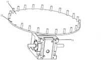
图1是本申请的一个实施例所提供的一种柱状物上条码视觉识别装置的整体结构示意图;FIG. 1 is a schematic diagram of the overall structure of a barcode visual recognition device on a column provided by an embodiment of the present application;
图2是本申请的一个实施例所提供的一种送料装置的结构示意图;Fig. 2 is a schematic structural view of a feeding device provided by an embodiment of the present application;
图3是本申请的一个实施例所提供的一种转动装置的结构示意图;Fig. 3 is a schematic structural diagram of a rotating device provided by an embodiment of the present application;
图4是本申请的一个实施例所提供的第一识别装置的结构示意图;Fig. 4 is a schematic structural diagram of a first identification device provided by an embodiment of the present application;
图5是本申请的一个实施例所提供的第二识别装置的结构示意图。Fig. 5 is a schematic structural diagram of a second identification device provided by an embodiment of the present application.
附图中:1、送料装置;2、转动装置;3、第一识别装置;4、第二识别装置;5、机架;6、柱状物;11、转动盘;12放置槽;13、间歇旋转机构;21、主动轮;22、伺服电机;23、从动轮;24、第一滑动块;25、第二滑动块;26、第三滑动块;27、第一弹性件;28、凸轮;29、第三转动轮;30、第二转动轮;31、第三滑动槽;32、第二滑动槽;33、第一转动轮。In the drawings: 1. Feeding device; 2. Rotating device; 3. First identification device; 4. Second identification device; 5. Rack; Rotary mechanism; 21, driving wheel; 22, servo motor; 23, driven wheel; 24, first sliding block; 25, second sliding block; 26, third sliding block; 27, first elastic member; 28, cam; 29, the third rotating wheel; 30, the second rotating wheel; 31, the third sliding groove; 32, the second sliding groove; 33, the first rotating wheel.
具体实施方式detailed description
为了使本申请的目的、技术方案及优点更加清楚明白,以下结合附图及实施例,对本申请进行进一步详细说明。应当理解,此处所描述的具体实施例仅仅用以解释本申请,并不用于限定本申请。In order to make the purpose, technical solution and advantages of the present application clearer, the present application will be further described in detail below in conjunction with the accompanying drawings and embodiments. It should be understood that the specific embodiments described here are only used to explain the present application, and are not intended to limit the present application.
以下结合具体实施例对本申请的具体实现进行详细描述。The specific implementation of the present application will be described in detail below in conjunction with specific embodiments.
如图1所示,为本申请实施例提供的一种柱状物上条码视觉识别装置的整体结构示意图,包括:送料装置1、转动装置2、第一识别装置3、第二识别装置4、机架5以及动力源;As shown in Figure 1, it is a schematic diagram of the overall structure of a barcode visual recognition device on a column provided in the embodiment of the present application, including: a feeding device 1, a rotating device 2, a
机架5,机架5上设置有动力源;
送料装置1,设置于机架5上,其上有若干柱状物6,送料装置1用于在动力源6的驱动下间歇输送柱状物6,柱状物6侧面具有条码;The feeding device 1 is arranged on the
第一识别装置3,位于送料装置1一侧,用于确定经过其识别范围的柱状物6上是否具有条码;The
转动装置2,用于转动第一识别装置3识别范围内的柱状物6,直至第一识别装置3的识别范围内出现条码;The rotating device 2 is used to rotate the
第二识别装置4,第二识别装置4用于扫描经过转动装置2转动的柱状物6上的条码。The
在本实施例的一种情况中,送料装置1可以为直线传送带的方式,也可以为旋转给料装置,本实施例为旋转给料装置。In one case of this embodiment, the feeding device 1 may be in the form of a linear conveyor belt, or may be a rotary feeding device, and this embodiment is a rotary feeding device.
在本实施例的一种情况中,识别范围为第一识别装置3镜头物的方端面到被拍摄柱状物6表面的物理距离为半径,形成的一段扇形区域,识别时识别范围内只有一个柱状物6,只对一个柱状物6进行识别。In one case of this embodiment, the recognition range is a fan-shaped area formed by the physical distance from the square end face of the lens object of the
在本实施例的一种情况中,第一识别装置3可以为工业相机。In one case of this embodiment, the
在本实施例的一种情况中,第二识别装置4可以为扫描器。In one case of this embodiment, the
在本实施例的一种情况中,柱状物6为圆柱状物体,例如瓶子、电池等,本实施例为电池。In one case of this embodiment, the
在本实施例的一种情况中,条码可为一维条码、二维条码或者三维条码。In one case of this embodiment, the barcode may be a one-dimensional barcode, a two-dimensional barcode or a three-dimensional barcode.
在本实施例的一种情况中,条码可能出现在第一识别装置3识别区域内任意位置,本实施例中条码通过转动装置2转动柱状物6,使其处于第一识别装置3的识别区域内,即柱状物6需正对第一识别装置3,来被第一识别装置3识别。In one case of this embodiment, the barcode may appear at any position within the identification area of the
在本实施例的一种情况中,送料装置1间歇送料的间歇时长根据工艺参数确定,本实施例中间歇时长为1秒。In one case of this embodiment, the intermittent duration of intermittent feeding by the feeding device 1 is determined according to process parameters, and the intermittent duration in this embodiment is 1 second.
在本实施例的一种情况中,送料装置1 用于在动力源的驱动下间歇输送柱状物6,第一识别装置3和第二识别装置4位于送料装置1一侧,同时两者一一对应设置有一个转动装置,柱状物6在第一识别装置3和第二识别装置4的识别区域内停留的间歇时长相同,第一识别装置3处于持续工作状态,用于确定经过其识别范围的柱状物6上是否具有条码,若未出现条码则第一识别装置3将未出现条码信息反馈到转动装置2,转动装置2在柱状物6停留的间歇时长内旋转柱状物6直至第一识别装置3的识别范围内出现条码,经过第一识别装置3的柱状物6,进入第二识别装置4的识别区域,第二识别装置4扫描柱状物6上的条码的特征信息。本申请通过设置两个识别装置的目的主要使是改变柱状物6上条码正对的方向,并且扫描记录条码的特征信息,为下一工序提前做好准备,两者之间的配合工作更加协调,使整个视觉识别装置的工作效率更高。In one case of this embodiment, the feeding device 1 is used to intermittently convey the
如图2所示,作为本申请的一种优选实施例,送料装置1包括转动盘11,转动盘11周向设置有若干放置槽12,放置槽12用于放置所述柱状物6,放置槽12均匀分布在转动盘11最外圈;间歇转动机构13,间歇转动机构13用于驱动转动盘11间歇转动,间歇转动机构13的出力轴与转动盘11固定连接,带动转动盘11间歇旋转,间歇转动机构13的入力轴与动力源连接。As shown in Fig. 2, as a kind of preferred embodiment of the present application, feeding device 1 comprises rotating
在本实施例的一种情况中,放置槽12为圆形凹槽,其直径比柱状物6大。设置较大直径放置槽12的目的是为柱状物6提供一个可移动转动的空间,同时可适应不同直径大小的柱状物6。In one case of this embodiment, the placing
在本实施例的一种情况中,间歇转动机构13可以为棘轮机构、槽轮机构、连杆机构和不完全齿轮机构等,本实施例中间歇转动机构13为凸轮分割器。In one case of this embodiment, the intermittent
如图4-5所示,作为本申请的一种优选实施例,第一识别装置3安置于所述机架5上,第一识别装置3用于识别经过其识别范围的柱状物6上条码是否正对第一识别装置3,以确定是否通过与之对应的转动装置2转动所述柱状物6;As shown in Figures 4-5, as a preferred embodiment of the present application, the
第二识别装置4安置于所述机架5上,第二识别装置4用于扫描已正对第一识别装置3的柱状物6的条码的特征信息,所述条码的特征信息包括条码的码制、长度和有无校验位。The
在本实施例的一种情况中,第二识别装置4安装在可调节识别角度支架上。以适应条码在柱状物6上不规则处的识别。In one case of this embodiment, the
在本实施例的一种情况中,若条码存在缺陷,则第二识别装置4进行多次的扫描,缺陷条码的特征信息无法被识别,将该未识别的条码与该柱状物关联标记,便于工作人员在下一工序中将该柱状物6捡出。In one case of this embodiment, if there is a defect in the barcode, the
在本实施例的一种情况中,第一识别装置3处于持续的工作下,实时反馈识别区域条码信息。In one case of this embodiment, the
如图4-图5所示,作为本申请的一种优选实施例,第一识别装置3和第二识别装置4对应设置有转动装置2,柱状物6被第一识别装置3扫描时其与第一识别装置3之间的相对位置,与其被第二识别装置4扫描时其与第二识别装置4的相对位置相同,举例说明,当某一个柱状物6上条码正对第一识别装置3时,第一识别装置3与该条码的连线的延长线指向转动盘11的圆心,当该柱状物6由转动盘11的旋转被到第二识别装置4扫描时,第二识别装置4与该条码的连线的延长线同样指向转动盘11的圆心,即第一识别装置3和第二识别装置4沿转动盘11外沿,呈扇形布置,两者的识别方向都指向转动盘11的圆心。在第二识别装置4对应设置转动装置,可以在第二识别装置4识别条码的特征信息后,再通过与第二识别装置4对应的转动装置转动柱状物6,使其转动一定的角度,来方便后续的检测等步骤。As shown in Figures 4-5, as a preferred embodiment of the present application, the
在本实施例的一种情况中,第一识别装置3的数量为两个。In one case of this embodiment, there are two
在本实施例的一种情况中,第二识别装置4的数量为一个。In one case of this embodiment, the number of the
如图3所示,作为本申请的一种优选实施例,转动装置2包括:转动机构,用于带动柱状物6旋转,转动机构可以设置多个能各自单独控制柱状物6旋转的部件,并且上述部件与识别装置一一对应,各个转动机构根据各个对应设置的第一识别装置3所反馈的条码信息,各自单独控制各自的柱状物6旋转;推拉装置,用于推动柱状物6与转动机构抵接,以使转动机构带动柱状物6旋转,推拉装置中设置有与转动机构一一对应的部件,通过驱动组件能同时对各个转动机构对应的各个柱状物6进行推拉,以使被送料装置1运送过来的柱状物6被夹紧,然后方便其被转动、识别。As shown in Figure 3, as a preferred embodiment of the present application, the rotating device 2 includes: a rotating mechanism for driving the rotation of the
在本实施例的一种情况中,转动机构为电机驱动转动轮的形式。In one case of this embodiment, the rotating mechanism is in the form of a motor-driven rotating wheel.
在本实施例的一种情况中,推拉装置为凸轮机构和滑槽滑块配合的形式。In one case of this embodiment, the push-pull device is in the form of a cam mechanism cooperating with a sliding block of the chute.
如图3所示,作为本申请的一种优选实施例,转动机构包括:主动轮21,主动轮21转动安装在机架5上,用于带动柱状物6旋转;伺服电机22,伺服电机22的主动轴上设置有主动轮21,伺服电机22用于驱动主动轮21旋转;As shown in Figure 3, as a kind of preferred embodiment of the present application, the rotating mechanism comprises: driving
推拉装置包括:驱动组件,驱动组件安装在机架5上,用于将动力与推拉装置连接,为推拉装置提供动力;传动组件,传动组件安装在机架5上,用于将驱动组件提供的动力传递到柱状物6。The push-pull device includes: a drive assembly, the drive assembly is installed on the
在本实施例的一种情况中,驱动组件与送料装置1的动力来源相同。In one case of this embodiment, the power source of the driving assembly and the feeding device 1 is the same.
在本实施例的一种情况中,传动组件为滑槽滑块结构。In one case of this embodiment, the transmission assembly is a chute slider structure.
如图3所示,作为本申请的一种优选实施例,传动组件包括:第一滑动块24,第一滑动块24横向滑动安装于机架5上,用于推动柱状物6与主动轮21抵接;从动轮23,从动轮23转动设置在第一滑动块24上,用于与主动轮23一同将柱状物6夹住;第二滑动块25,第二滑动块25滑动安装在机架5上,用于带动第一滑动块24滑动;驱动组件包括:第三滑动块26,第三滑动块26竖向滑动安装在机架5上,用于带动第二滑动块25滑动;凸轮28,凸轮28与所动力源5同步转动,用于使第三滑动块26间歇在竖直方向上滑动;第一弹性件27,第一弹性件27一端固定在第三滑动块26上,另一端固定在机架5上,用于使第三滑动块26与凸轮28抵接。As shown in Figure 3, as a preferred embodiment of the present application, the transmission assembly includes: a first sliding
在本实施例的一种情况中,第三滑动块26的形状为L形板,L形板靠近第二滑动块25的一端设置有第三滑动槽31,第三滑动槽31滑动配合第二滑动块25上的第二转动轮30,将第三滑动块26的上下移动转变成第二滑动块25的横向移动,L形板靠近凸轮28的一端转动设有与凸轮28配合的第三转动轮29,第三转动轮29将凸轮28的转动转变成第三滑动块26的移动,L形板中间处固定连接第一弹性件27的一端,第一弹性件27另一端固定连接在机架5上,第一弹性件27使第三滑动块26与凸轮28抵接。In one case of this embodiment, the third sliding
在本实施例的一种情况中,第一弹性件27为弹簧。In one case of this embodiment, the first
在本实施例的一种情况中,第二滑动块25的形状为T形板,T形板靠近转动盘11的一端设置有三个第二滑动槽32,第二滑动槽32配合第一滑动块24上的第一转动轮33,将第二滑动块25的横向移动转变成三个第一滑动块24沿转动盘11径向的移动,T形板靠近第三滑动块26的一端设置有第二转动轮30,第二转动轮30与第三滑动块26上的第三滑动槽31滑动配合。In one case of this embodiment, the second sliding
在本实施例的一种情况中,第二滑动块25的形状根据第一滑动块24的数量确定,本实施例中第一滑动块24的数量为三个。In one case of this embodiment, the shape of the second sliding
在本实施例的一种情况中,第一滑动块24在第二滑动块25的下方,第一滑动块24上设置有与第二滑动块25上第二滑动槽32配合的第一转动轮33,第一滑动块24转动设置有从动轮23,用于与主动轮21夹持柱状物6,从动轮23的数量为四个,上下两两布置。In one case of this embodiment, the first sliding
在本实施例的一种情况中,从动轮6可为固定的夹持角度,也可选择为弹性连接的方式,改变其夹持角度,能夹持不同直径的柱状物。In one case of this embodiment, the driven
如图1所示,作为本申请的一种优选实施例,第一识别装置3为工业相机,工业相机数量为两个;工业相机一一对应设置有转动装置2;第二识别装置4为扫描器,扫描器数量为一个;扫描器对应设置有转动装置2;转动装置2用于使柱状物6旋转固定角度,所述固定角度为预设的固定数值。As shown in Figure 1, as a preferred embodiment of the present application, the
示例性的,在本实施例中,工业相机的数量为两个,扫描器的数量为一个,三者呈扇形依次布置在转动盘11的一侧,主动轮21的数量为三个,与工业相机和扫描器一一对应,扇形的弧度与转动盘11的弧度相同,相互之间等距,主动轮21一一对应的转动盘6上设置有放置槽12,放置槽12均匀布置在转动盘11的外圈上,放置槽12的直径较柱状物6的大,柱状物6放置在放置槽12内,可以滑动。条码识别装置工作时,柱状物6进入工业相机的识别区域对应的主动轮21和从动轮23之间,此时转动盘11间歇的停止旋转,柱状物6在每个主动轮21和从动轮23之间停留的间隔时长相同,工业相机持续工作,实时的判断识别区域内条码是否正对工业相机,并将反馈信息发送给伺服电机22,伺服电机22依此判断是否需要带动柱状物6旋转。比如,柱状物6在被主动轮和从动轮夹持并被第一个工业相机识别时,存在两种情况,一种情况是:柱状物6条码处在正对工业相机的位置,此时无需旋转柱状物6;一种情况是:柱状物6条码不处在正对工业相机的位置,此时需要转送柱状物6,但又存在两种情况,一种情况是:在间隔时长内,柱状物6上条码可以被转动到正对工业相机的位置,一种情况是:在间隔时长内,柱状物6经过转动后其上条码仍然无法正对工业相机。因此,柱状物6在第一个工业相机识别后,若柱状物6上的条码已正对工业相机,则柱状物6被第二个工业相机识别时,柱状物6无需旋转;若柱状物6上的条码仍未正对工业相机,则柱状物6被第二个工业相机识别时,柱状物6被转动装置转动,使条码正对工业相机。柱状物6经过两个主动轮21和从动轮23之间后,条码已在正对工业相机的位置,然后进入扫描器识别区域对应的主动轮21和从动轮23之间,待扫描器识别条码特征信息后,主动轮21带动柱状物6旋转固定的角度,所述固定角度为预设的固定数值,将所有经过条码识别装置的柱状物上条码面对的方向统一,便于下一工序的检测。Exemplarily, in this embodiment, the number of industrial cameras is two, the number of scanners is one, and the three are arranged in a fan shape on one side of the
设置两个工业相机并对应设置有两个转动装置的目的是,避免通过一个转动装置转动主动轮时,在一个主动轮21和从动轮23之间内柱状物停留的间隔时长无法使柱状物6上条码通过主动轮21旋转到正对工业相机的位置。工业相机的数量与柱状物停留的间隔时长相关,本实施例中,间隔时长内,柱状物旋转的最大角度为180°,则工业相机设置有两个,可以理解的,间隔时长内,柱状物旋转的最大角度为120°,则工业相机设置有3个。通过设置两个工业相机以及两个转动装置,使送料装置和转动装置在时间上的配合更加合理,两者之间的配合工作更加协调,使整个视觉识别装置的工作效率更高。The purpose of arranging two industrial cameras and correspondingly having two rotating devices is to avoid that when the driving wheel is rotated by a rotating device, the length of the interval between the stay of the column between a
转动装置2是这样工作的:动力源6在驱动转动盘11间歇旋转的同时,通过凸轮28、第三滑动块26、第二滑动块25使第一滑动块24间歇的移动,柱状物6停留在主动轮21和从动轮23之间的同时,第一滑动块24推动柱状物6与主动轮抵接,当柱状物6需要移动时,第一滑动块24与柱状物6分离。示例性的,凸轮28在动力源6的驱动下转动,当凸轮28的凸缘推动第三滑动块26向上移动,第三滑动块26上第三滑动槽31配合第二转动轮30滑动,第二转动轮25被第三滑动槽30向前推动同时带动第二滑动块25向前,第二滑动块25上第二滑动槽32向前,第一转动轮33被第二滑动槽32向前推动同时带动第一滑动块24向转动盘11径向方向移动,从而第一滑动块24与柱状物6分离。转动装置2和送料装置1通过同一动力源驱动,并使送料装置1和推拉装置之间以固定的时间间隔配合工作,来对柱状物6的条码进行逐一识别。The rotating device 2 works like this: when the
在本实施例的一种情况中,视觉识别装置还包括控制系统,该控制系统与上述的送料装置、第一识别装置、第二识别装置、转动装置等直接或者间接连接,用于控制上述机构的协调工作;进一步的,该控制系统中存储有控制程序,该控制程序被运行时,可以控制上述机构执行上述的操作流程。当然,在另一种情况中,可以理解,条码识别装置还可通过半自动的形式实现,其中的部分操作流程也可以由人工配合实现,比如,控制扫描器识别区域等,具体不作限制。In one case of this embodiment, the visual identification device further includes a control system, which is directly or indirectly connected to the above-mentioned feeding device, first identification device, second identification device, rotating device, etc., and is used to control the above-mentioned mechanism further, the control system stores a control program, and when the control program is run, it can control the above-mentioned mechanism to execute the above-mentioned operation flow. Of course, in another case, it can be understood that the barcode recognition device can also be realized in a semi-automatic form, and some of the operation procedures can also be realized manually, such as controlling the scanner recognition area, etc., without specific limitation.
上文的实施例中,提供了一种柱状物上条码视觉识别装置,通过送料装置、第一识别装置、第二识别装置、转动装置等的巧妙配合,实现了柱状物上条码的自动识别;综合来看,上述条码识别装置实现了条码的全自动识别,生产效率大大提高,相应的,生产成本也大幅度降低。In the above embodiment, a barcode visual recognition device on a pillar is provided, through the ingenious cooperation of the feeding device, the first recognition device, the second recognition device, the rotating device, etc., the automatic recognition of the barcode on the pillar is realized; On the whole, the above-mentioned barcode recognition device realizes the automatic recognition of barcodes, the production efficiency is greatly improved, and correspondingly, the production cost is also greatly reduced.
以上所述仅为本申请的较佳实施例而已,并不用以限制本申请,凡在本申请的精神和原则之内所作的任何修改、等同替换和改进等,均应包含在本发明的保护范围之内。The above is only a preferred embodiment of the application, and is not intended to limit the application. Any modifications, equivalent replacements and improvements made within the spirit and principles of the application should be included in the protection of the present invention. within range.
Claims (10)
Priority Applications (1)
| Application Number | Priority Date | Filing Date | Title |
|---|---|---|---|
| CN202210994839.6ACN115438679A (en) | 2022-08-18 | 2022-08-18 | Bar code visual identification device on column |
Applications Claiming Priority (1)
| Application Number | Priority Date | Filing Date | Title |
|---|---|---|---|
| CN202210994839.6ACN115438679A (en) | 2022-08-18 | 2022-08-18 | Bar code visual identification device on column |
Publications (1)
| Publication Number | Publication Date |
|---|---|
| CN115438679Atrue CN115438679A (en) | 2022-12-06 |
Family
ID=84243133
Family Applications (1)
| Application Number | Title | Priority Date | Filing Date |
|---|---|---|---|
| CN202210994839.6APendingCN115438679A (en) | 2022-08-18 | 2022-08-18 | Bar code visual identification device on column |
Country Status (1)
| Country | Link |
|---|---|
| CN (1) | CN115438679A (en) |
Citations (6)
| Publication number | Priority date | Publication date | Assignee | Title |
|---|---|---|---|---|
| US20050279419A1 (en)* | 2004-06-21 | 2005-12-22 | Dennis Tribble | Automated use of a vision system to unroll a label to capture and process drug identifying indicia present on the label |
| CN210155699U (en)* | 2019-09-20 | 2020-03-17 | 苏州新实医疗科技有限公司 | A full information acquisition equipment for blake bottle |
| CN111077331A (en)* | 2019-12-25 | 2020-04-28 | 中科精瓒(武汉)医疗技术有限公司 | Sample disc of thrombelastogram instrument |
| CN212624055U (en)* | 2020-05-25 | 2021-02-26 | 南京玄铁自动化科技有限公司 | Code reading device for realizing 360-degree rotation of columnar product |
| CN213365524U (en)* | 2020-12-14 | 2021-06-04 | 湖州职业技术学院 | Automatic logistics information detecting device |
| CN114339046A (en)* | 2021-12-30 | 2022-04-12 | 中元汇吉生物技术股份有限公司 | Image acquisition method, device, equipment and medium based on automatic rotation test tube |
- 2022
- 2022-08-18CNCN202210994839.6Apatent/CN115438679A/enactivePending
Patent Citations (6)
| Publication number | Priority date | Publication date | Assignee | Title |
|---|---|---|---|---|
| US20050279419A1 (en)* | 2004-06-21 | 2005-12-22 | Dennis Tribble | Automated use of a vision system to unroll a label to capture and process drug identifying indicia present on the label |
| CN210155699U (en)* | 2019-09-20 | 2020-03-17 | 苏州新实医疗科技有限公司 | A full information acquisition equipment for blake bottle |
| CN111077331A (en)* | 2019-12-25 | 2020-04-28 | 中科精瓒(武汉)医疗技术有限公司 | Sample disc of thrombelastogram instrument |
| CN212624055U (en)* | 2020-05-25 | 2021-02-26 | 南京玄铁自动化科技有限公司 | Code reading device for realizing 360-degree rotation of columnar product |
| CN213365524U (en)* | 2020-12-14 | 2021-06-04 | 湖州职业技术学院 | Automatic logistics information detecting device |
| CN114339046A (en)* | 2021-12-30 | 2022-04-12 | 中元汇吉生物技术股份有限公司 | Image acquisition method, device, equipment and medium based on automatic rotation test tube |
Similar Documents
| Publication | Publication Date | Title |
|---|---|---|
| CN110340534B (en) | High-speed laser coding machine and coding method | |
| CN110315346B (en) | Automated processing system and automated processing method | |
| CN107234615B (en) | Workpiece placement system, workpiece placement device and workpiece placement control method | |
| CN103909069A (en) | Full-automatic intelligent sheet selection machine for neodymium-iron-boron magnetic workpieces based on machine vision | |
| CN209858453U (en) | Liquid crystal display panel inspection machine | |
| CN113858818A (en) | Marking system | |
| CN108759679B (en) | Coffee boiler size detection equipment and detection method | |
| CN109420849A (en) | A kind of automatic laser marking machine | |
| CN113290323A (en) | Tire laser marking machine and marking method | |
| CN106645193A (en) | On-line detection apparatus | |
| CN111010563A (en) | A mobile phone camera module multifunctional test equipment | |
| CN114918868A (en) | Assembly mechanism for flexible mixed wire and control method thereof | |
| CN110626587A (en) | Labeling system, labeling method and labeling device | |
| CN207900078U (en) | A kind of automation lock screw marking equipment | |
| CN113102600A (en) | Automatic stamping system | |
| CN115438679A (en) | Bar code visual identification device on column | |
| CN112536539B (en) | Laser processing equipment loading system and method | |
| CN111300364A (en) | Integrated intelligent material warehouse | |
| WO2020082505A1 (en) | Marker rod assembly device, fully automatic production line and marker rod assembly method | |
| CN210549493U (en) | Automatic change system of processing | |
| CN110369335B (en) | Automatic AOI Backlight Inspection Equipment | |
| CN115945884B (en) | Novel automatic check ring assembly equipment | |
| CN213792895U (en) | Automatic detection device of wireless charger | |
| CN216990354U (en) | Tire laser marking machine | |
| CN217393026U (en) | Gear product automated inspection machine |
Legal Events
| Date | Code | Title | Description |
|---|---|---|---|
| PB01 | Publication | ||
| PB01 | Publication | ||
| SE01 | Entry into force of request for substantive examination | ||
| SE01 | Entry into force of request for substantive examination |