CN115437136A - A double-light multi-magnification aiming optical system - Google Patents
A double-light multi-magnification aiming optical systemDownload PDFInfo
- Publication number
- CN115437136A CN115437136ACN202211226591.5ACN202211226591ACN115437136ACN 115437136 ACN115437136 ACN 115437136ACN 202211226591 ACN202211226591 ACN 202211226591ACN 115437136 ACN115437136 ACN 115437136A
- Authority
- CN
- China
- Prior art keywords
- light
- imaging subsystem
- magnification
- group
- objective lens
- Prior art date
- Legal status (The legal status is an assumption and is not a legal conclusion. Google has not performed a legal analysis and makes no representation as to the accuracy of the status listed.)
- Pending
Links
Images

Classifications
- G—PHYSICS
- G02—OPTICS
- G02B—OPTICAL ELEMENTS, SYSTEMS OR APPARATUS
- G02B23/00—Telescopes, e.g. binoculars; Periscopes; Instruments for viewing the inside of hollow bodies; Viewfinders; Optical aiming or sighting devices
- G02B23/02—Telescopes, e.g. binoculars; Periscopes; Instruments for viewing the inside of hollow bodies; Viewfinders; Optical aiming or sighting devices involving prisms or mirrors
- G02B23/04—Telescopes, e.g. binoculars; Periscopes; Instruments for viewing the inside of hollow bodies; Viewfinders; Optical aiming or sighting devices involving prisms or mirrors for the purpose of beam splitting or combining, e.g. fitted with eyepieces for more than one observer
- G—PHYSICS
- G02—OPTICS
- G02B—OPTICAL ELEMENTS, SYSTEMS OR APPARATUS
- G02B7/00—Mountings, adjusting means, or light-tight connections, for optical elements
- G02B7/02—Mountings, adjusting means, or light-tight connections, for optical elements for lenses
- G02B7/04—Mountings, adjusting means, or light-tight connections, for optical elements for lenses with mechanism for focusing or varying magnification
- G02B7/10—Mountings, adjusting means, or light-tight connections, for optical elements for lenses with mechanism for focusing or varying magnification by relative axial movement of several lenses, e.g. of varifocal objective lens
Landscapes
- Physics & Mathematics (AREA)
- General Physics & Mathematics (AREA)
- Optics & Photonics (AREA)
- Astronomy & Astrophysics (AREA)
- Lenses (AREA)
Abstract
Translated fromChinese
Description
Translated fromChinese技术领域technical field
本发明涉及光学系统领域,特别是涉及一种双光多倍率瞄准光学系统。The invention relates to the field of optical systems, in particular to a dual-light multi-magnification collimating optical system.
背景技术Background technique
当前,红外-可见光双光瞄准镜广泛应用于狩猎领域,使全天候狩猎成为可能,但在某些狩猎场景中,对于距离瞄准镜一定距离的目标而言,其体形过小或者环境场景范围过大,会导致难以在环境中找到目标,尤其是在夜间的环境中。另外对于想要观察目标细节的需求,目前的单倍率瞄准镜难以满足,即使某些双光瞄准镜提供数码变焦,即通过缩放图像尺寸的方式来放大目标,然而这种方式也会把图像内在的像差成比例放大,造成图像变得不清晰。At present, infrared-visible light dual-light sights are widely used in the field of hunting, making all-weather hunting possible, but in some hunting scenes, for targets at a certain distance from the sight, their body size is too small or the scope of the environmental scene is too large , which can make it difficult to find targets in the environment, especially at night. In addition, the current single-magnification scope is difficult to meet the demand for observing the details of the target. Even if some dual-optical scopes provide digital zoom, that is, to zoom in on the target by scaling the image size, this method will also magnify the image. The aberration is proportionally enlarged, causing the image to become unclear.
因此,需要一种双光瞄准光学系统,可以在范围较大且复杂的环境下可快速地搜索目标,同时也能够对目标的具体细节信息进行观察,以提高狩猎体验,以及对于具有广阔场地的畜牧业而言,使用该系统可以全天候大范围搜寻和小范围锁定入侵物种(如狼、老鼠等),对于保护场地和饲养动物具有重要的意义。Therefore, there is a need for a dual-light aiming optical system, which can quickly search for targets in a large and complex environment, and can also observe the specific details of the target to improve the hunting experience, and for those with a wide field. As far as animal husbandry is concerned, the system can be used to search in a large area around the clock and lock invasive species (such as wolves, mice, etc.) in a small area, which is of great significance for protecting the site and raising animals.
发明内容Contents of the invention
本发明的目的是提供一种双光多倍率瞄准光学系统,可以同时进行两种波段光的成像,并且放大倍率可改变,可以进行不同大小视野范围的观察,使得使用本瞄准光学系统可以在范围较大且复杂的环境下快速地搜索目标,也能够对目标的具体细节进行观察。The purpose of the present invention is to provide a dual-light multi-magnification aiming optical system, which can simultaneously perform imaging of two wavebands of light, and the magnification can be changed, and observation of different sizes of field of view can be performed, so that the aiming optical system can be used in a range of It can quickly search for targets in a large and complex environment, and can also observe the specific details of the target.
为实现上述目的,本发明提供如下技术方案:To achieve the above object, the present invention provides the following technical solutions:
一种双光多倍率瞄准光学系统,包括第一成像子系统、第二成像子系统以及目镜,所述第一成像子系统和所述第二成像子系统分别用于捕获物方光线的不同波段光线并基于捕获到的光线进行成像,还分别使成像获得的第一图像和第二图像的光线入射至所述目镜;A dual-light multi-magnification aiming optical system, including a first imaging subsystem, a second imaging subsystem, and an eyepiece, the first imaging subsystem and the second imaging subsystem are used to capture different wavelength bands of object-side light light and perform imaging based on the captured light, and respectively make the light of the first image and the second image obtained by imaging enter the eyepiece;
其中,所述第一成像子系统和所述第二成像子系统共用共口径物镜,所述共口径物镜的焦距可改变,使得所述第一成像子系统和所述第二成像子系统的放大倍率可改变。Wherein, the first imaging subsystem and the second imaging subsystem share a common-aperture objective lens, and the focal length of the common-aperture objective lens can be changed, so that the magnification of the first imaging subsystem and the second imaging subsystem The magnification can be changed.
可选地,所述共口径物镜包括固定组和移动组,所述固定组的位置不变,所述移动组相对于所述固定组的距离可改变,以改变所述共口径物镜的焦距,使得所述第一成像子系统和所述第二成像子系统的放大倍率可改变;Optionally, the common-aperture objective lens includes a fixed group and a moving group, the position of the fixed group remains unchanged, and the distance of the moving group relative to the fixed group can be changed to change the focal length of the common-aperture objective lens, making the magnification of the first imaging subsystem and the second imaging subsystem variable;
其中,当所述移动组相对于所述固定组的距离不同时,所述共口径物镜的焦距不同,对应的物方视场角也不同。Wherein, when the distances between the moving group and the fixed group are different, the focal lengths of the common-aperture objective lenses are different, and the corresponding object field angles are also different.
可选地,所述共口径物镜的镜筒内沿轴向在所述移动组的两侧分别设置有电磁部,所述移动组的边缘设置有具备永磁体特性的固定结构件;Optionally, in the lens barrel of the common-aperture objective lens, electromagnetic parts are respectively arranged on both sides of the moving group along the axial direction, and fixed structural members with permanent magnet characteristics are arranged on the edge of the moving group;
当任一所述电磁部对所述固定结构件产生磁吸力时,所述固定结构件带动所述移动组向该所述电磁部移动,使所述移动组移动至该电磁部对应的移动组位置,各个所述电磁部对应的移动组位置相对于所述固定组的距离分别不同。When any of the electromagnetic parts generates a magnetic attraction force on the fixed structure, the fixed structure drives the moving group to move to the electromagnetic part, so that the moving group moves to the corresponding moving group of the electromagnetic part The position of the moving group corresponding to each electromagnetic part is different from the fixed group.
可选地,在所述镜筒内,在每个所述电磁部对应的移动组位置处设置有用于固定所述移动组的限位槽。Optionally, in the lens barrel, a limit slot for fixing the moving group is provided at a position of the moving group corresponding to each electromagnetic part.
可选地,所述限位槽包括第一限位结构件和第二限位结构件,所述第一限位结构件和所述第二限位结构件之间的间隔形成槽;Optionally, the limit groove includes a first limit structure and a second limit structure, and the interval between the first limit structure and the second limit structure forms a groove;
所述第一限位结构件比所述第二限位结构件靠近对应的所述电磁部,所述固定结构件仅可正向通过所述第一限位结构件,所述固定结构件可正向以及反向通过所述第二限位结构件,正向是指背离对应的所述电磁部的方向,反向是指朝向对应的所述电磁部的方向。The first limit structure is closer to the corresponding electromagnetic part than the second limit structure, the fixed structure can only pass through the first limit structure in the forward direction, and the fixed structure can The forward direction and the reverse direction pass through the second limiting structure, the forward direction refers to the direction away from the corresponding electromagnetic part, and the reverse direction refers to the direction toward the corresponding electromagnetic part.
可选地,所述第一限位结构件设置有传感器,所述传感器用于检测所述第一限位结构件是否与所述固定结构件接触,以当检测到所述第一限位结构件与所述固定结构件接触时控制对应的所述电磁部停止产生磁吸力。Optionally, the first limit structure is provided with a sensor, and the sensor is used to detect whether the first limit structure is in contact with the fixed structure, so that when the first limit structure is detected When the component is in contact with the fixed structural component, the corresponding electromagnetic part is controlled to stop generating magnetic attraction force.
可选地,所述第一成像子系统包括所述共口径物镜、分光转向元件、转向组件和转向融合元件,所述第二成像子系统包括所述共口径物镜、所述分光转向元件、图像处理装置和所述转向融合元件;Optionally, the first imaging subsystem includes the common-aperture objective lens, the light splitting turning element, a turning assembly, and a turning fusion element, and the second imaging subsystem includes the common-aperture objective lens, the light splitting turning element, an image a treatment device and said steering fusion element;
所述分光转向元件设置于所述共口径物镜的出光光路上,用于将通过所述共口径物镜进入的物方光线中第一波段光线分出,使第一波段光线经过所述转向组件折转传播方向后入射至所述转向融合元件,以及将通过所述共口径物镜进入的物方光线中第二波段光线分出,使第二波段光线入射至所述图像处理装置;The light splitting and turning element is arranged on the light exit path of the common-aperture objective lens, and is used to separate the first-waveband light from the object-side light entering through the common-aperture objective lens, so that the first-waveband light is refracted by the turning assembly After turning the propagation direction, it enters the steering fusion element, and separates the second-waveband light from the object-side light entering through the common-aperture objective lens, so that the second-waveband light is incident on the image processing device;
所述图像处理装置用于基于接收到的第二波段光线进行光电转换和成像并将成像获得的所述第二图像显示,使显示的所述第二图像的光线入射至所述转向融合元件,所述目镜设置于所述转向融合元件的出光一侧,所述转向融合元件用于将所述第一图像的光线和第二图像的光线融合并进入所述目镜。The image processing device is used to perform photoelectric conversion and imaging based on the received light of the second wavelength band and display the second image obtained by imaging, so that the light of the displayed second image enters the steering fusion element, The eyepiece is disposed on the light output side of the steering fusion element, and the steering fusion element is used to fuse the light of the first image and the light of the second image into the eyepiece.
可选地,所述第一成像子系统还包括设置于所述分光转向元件和所述转向融合元件之间的第一中继透镜组,所述第一中继透镜组用于校正由所述分光转向元件出射的第一波段光线的光束口径和波前;Optionally, the first imaging subsystem further includes a first relay lens group disposed between the light splitting and turning element and the turning and fusion element, the first relay lens group is used to correct the The beam aperture and wavefront of the first-band light emitted by the light splitting and diverting element;
所述第二成像子系统还包括设置于所述图像处理装置和所述转向融合元件之间的第二中继透镜组,所述第二中继透镜组用于将所述图像处理装置显示的第二图像成像到所述转向融合元件中,以校正所述第二图像光线的光束口径和波前。The second imaging subsystem also includes a second relay lens group disposed between the image processing device and the steering fusion element, the second relay lens group is used to display the image processing device A second image is imaged into the steering fusion element to correct the beam aperture and wavefront of the light rays of the second image.
可选地,所述第一中继透镜组和所述第二中继透镜组使到达所述转向融合元件的所述第一图像光线的光束口径和波前,分别与到达所述转向融合元件的所述第二图像光线的光束口径和波前一致。Optionally, the first relay lens group and the second relay lens group make the beam aperture and wavefront of the first image light reaching the steering fusion element respectively different from those reaching the steering fusion element The beam aperture of the second image light is consistent with the wavefront.
可选地,所述转向组件包括设置于所述分光转向元件和所述第一中继透镜组之间的转向元件,以及设置于所述第一中继透镜组和所述转向融合元件之间的转向元件。Optionally, the turning assembly includes a turning element arranged between the light splitting turning element and the first relay lens group, and a turning element arranged between the first relay lens group and the turning fusion element steering components.
可选地,所述图像处理装置包括依次连接的光电传感器、图像处理系统和显示屏,所述光电传感器用于基于接收到的第二波段光线进行光电转换,所述图像处理系统用于将获得的成像信息进行处理,所述显示屏用于将处理后的成像信息以可见光的形式显示。Optionally, the image processing device includes a photoelectric sensor, an image processing system and a display screen connected in sequence, the photoelectric sensor is used to perform photoelectric conversion based on the received light of the second wavelength band, and the image processing system is used to obtain The imaging information is processed, and the display screen is used to display the processed imaging information in the form of visible light.
可选地,所述第一成像子系统还包括标有分划线的透光的分划板,所述分划板设置于所述分光转向元件的第一波段光线的出射光路上,且位于所述共口径物镜的焦平面上;所述图像处理装置的显示屏设置有分划线。Optionally, the first imaging subsystem further includes a light-transmitting reticle marked with a reticle, and the reticle is arranged on the outgoing optical path of the light of the first wavelength band of the light splitting and diverting element, and is located at On the focal plane of the common-aperture objective lens; the display screen of the image processing device is provided with a reticle.
可选地,在所述分划板的一侧设置有照明器件,所述照明器件用于出射光以照亮所述分划线。Optionally, an illuminating device is provided on one side of the reticle, and the illuminating device is used to emit light to illuminate the reticle.
由上述技术方案可知,本发明所提供的一种双光多倍率瞄准光学系统,包括第一成像子系统、第二成像子系统以及目镜,第一成像子系统和第二成像子系统分别用于捕获物方光线的不同波段光线并基于捕获到的光线进行成像,还分别使成像获得的第一图像和第二图像的光线入射至目镜。其中,第一成像子系统和第二成像子系统共用共口径物镜,共口径物镜的焦距可改变,使得第一成像子系统和第二成像子系统的放大倍率可改变。It can be seen from the above technical solution that a dual-light multi-magnification aiming optical system provided by the present invention includes a first imaging subsystem, a second imaging subsystem and an eyepiece, and the first imaging subsystem and the second imaging subsystem are respectively used for Light rays of different wavelength bands of the object-side light are captured and imaging is performed based on the captured light rays, and the light rays of the first image and the second image obtained by imaging are respectively incident on the eyepiece. Wherein, the first imaging subsystem and the second imaging subsystem share a common-aperture objective lens, and the focal length of the common-aperture objective lens can be changed, so that the magnification of the first imaging subsystem and the second imaging subsystem can be changed.
因此,本发明的双光多倍率瞄准光学系统可以同时进行两种波段光的成像,并且放大倍率可改变,可以进行不同大小视野范围的观察,当调节本瞄准光学系统的放大倍率较小时,可以使用本瞄准光学系统在范围较大且复杂的环境下搜索目标,使用本瞄准光学系统对目标的具体细节进行观察时,可以调节本瞄准光学系统的放大倍率较大。因此使用本瞄准光学系统可以在范围较大且复杂的环境下快速地搜索目标,也能够对目标的具体细节进行观察。Therefore, the dual-light multi-magnification aiming optical system of the present invention can perform imaging of two kinds of waveband lights simultaneously, and the magnification can be changed, and observation of different sizes of field of view can be carried out. When the magnification of the adjustment of the aiming optical system is small, Use the aiming optical system to search for targets in a large and complex environment. When using the aiming optical system to observe the specific details of the target, the magnification of the aiming optical system can be adjusted to be larger. Therefore, the aiming optical system can be used to quickly search for a target in a large and complex environment, and can also observe specific details of the target.
附图说明Description of drawings
为了更清楚地说明本发明实施例或现有技术中的技术方案,下面将对实施例或现有技术描述中所需要使用的附图作简单地介绍,显而易见地,下面描述中的附图仅仅是本发明的一些实施例,对于本领域普通技术人员来讲,在不付出创造性劳动的前提下,还可以根据这些附图获得其他的附图。In order to more clearly illustrate the technical solutions in the embodiments of the present invention or the prior art, the following will briefly introduce the drawings that need to be used in the description of the embodiments or the prior art. Obviously, the accompanying drawings in the following description are only These are some embodiments of the present invention. Those skilled in the art can also obtain other drawings based on these drawings without creative work.
图1为本发明一实施例提供的一种双光多倍率瞄准光学系统的结构框图;Fig. 1 is a structural block diagram of a dual-light multi-magnification aiming optical system provided by an embodiment of the present invention;
图2为本发明一实施例提供的一种双光多倍率瞄准光学系统的结构示意图;Fig. 2 is a schematic structural diagram of a dual-light multi-magnification aiming optical system provided by an embodiment of the present invention;
图3为本发明一实施例的共口径物镜的移动组的示意图。FIG. 3 is a schematic diagram of a moving group of a common-aperture objective lens according to an embodiment of the present invention.
说明书附图中的附图标记包括:The reference signs in the accompanying drawings of the specification include:
人眼-100,共口径物镜-101,分光转向元件-102,分划板-103,转向元件-104,第一中继透镜组-105,图像处理装置-106,第二中继透镜组-107,转向融合元件-108,目镜-109,固定组-110,移动组-111,光电传感器-112,显示屏-113,镜筒-114;Human eye-100, common aperture objective lens-101, beam splitting and turning element-102, reticle-103, turning element-104, first relay lens group-105, image processing device-106, second relay lens group- 107, steering fusion element-108, eyepiece-109, fixed group-110, moving group-111, photoelectric sensor-112, display screen-113, lens barrel-114;
第一电磁部-201,第二电磁部-202,固定结构件-203,第一限位结构件-204,第二限位结构件-205。The first electromagnetic part-201, the second electromagnetic part-202, the fixed structure part-203, the first limit structure part-204, and the second limit structure part-205.
具体实施方式detailed description
为了使本技术领域的人员更好地理解本发明中的技术方案,下面将结合本发明实施例中的附图,对本发明实施例中的技术方案进行清楚、完整地描述,显然,所描述的实施例仅仅是本发明一部分实施例,而不是全部的实施例。基于本发明中的实施例,本领域普通技术人员在没有做出创造性劳动前提下所获得的所有其他实施例,都应当属于本发明保护的范围。In order to enable those skilled in the art to better understand the technical solutions in the present invention, the technical solutions in the embodiments of the present invention will be clearly and completely described below in conjunction with the drawings in the embodiments of the present invention. Obviously, the described The embodiments are only some of the embodiments of the present invention, not all of them. Based on the embodiments of the present invention, all other embodiments obtained by persons of ordinary skill in the art without making creative efforts shall fall within the protection scope of the present invention.
本实施例提供一种双光多倍率瞄准光学系统,包括第一成像子系统、第二成像子系统以及目镜,所述第一成像子系统和所述第二成像子系统分别用于捕获物方光线的不同波段光线并基于捕获到的光线进行成像,还分别使成像获得的第一图像和第二图像的光线入射至所述目镜;This embodiment provides a dual-light multi-magnification aiming optical system, including a first imaging subsystem, a second imaging subsystem, and an eyepiece, and the first imaging subsystem and the second imaging subsystem are respectively used to capture the The rays of different wavelength bands of light are imaged based on the captured light, and the light rays of the first image and the second image obtained by imaging are respectively incident on the eyepiece;
其中,所述第一成像子系统和所述第二成像子系统共用共口径物镜,所述共口径物镜的焦距可改变,使得所述第一成像子系统和所述第二成像子系统的放大倍率可改变。Wherein, the first imaging subsystem and the second imaging subsystem share a common-aperture objective lens, and the focal length of the common-aperture objective lens can be changed, so that the magnification of the first imaging subsystem and the second imaging subsystem The magnification can be changed.
第一成像子系统的物镜和第二成像子系统的物镜为同一透镜组,两者共用共口径物镜作为物镜。那么,第一成像子系统和第二成像子系统的视场角相同,放大倍率相同。The objective lens of the first imaging subsystem and the objective lens of the second imaging subsystem are the same lens group, and both share a common aperture objective lens as the objective lens. Then, the first imaging subsystem and the second imaging subsystem have the same field of view and the same magnification.
本实施例的双光多倍率瞄准光学系统可以同时进行两种波段光的成像,并且成像倍率可改变,可以进行不同大小视野范围的观察,当调节本瞄准光学系统的放大倍率较小时,可以使用本瞄准光学系统在范围较大且复杂的环境下搜索目标,使用本瞄准光学系统对目标的具体细节进行观察时,可以调节本瞄准光学系统的放大倍率较大。因此使用本瞄准光学系统可以在范围较大且复杂的环境下快速地搜索目标,也能够对目标的具体细节进行观察。The dual-light multi-magnification aiming optical system of this embodiment can simultaneously perform imaging of two wavebands of light, and the imaging magnification can be changed, and observation of different sizes of field of view can be performed. When the magnification of the aiming optical system is adjusted to be small, it can be used The aiming optical system searches for targets in a large and complex environment. When using the aiming optical system to observe the specific details of the target, the magnification of the aiming optical system can be adjusted to be larger. Therefore, the aiming optical system can be used to quickly search for a target in a large and complex environment, and can also observe specific details of the target.
第一波段光线可以是可见光,第二波段光线可以是红外光,那么本瞄准光学系统可以同时进行可见光成像以及红外光成像,能够用于全天候观测;并且,通过目镜可以观察到基于第一波段光线成像的第一图像和基于第二波段光线成像的第二图像融合的图像,那么,本瞄准光学系统可以通过可见光-红外光图像融合技术实现全天候的观测。The first band of light can be visible light, and the second band of light can be infrared light, then the aiming optical system can simultaneously perform visible light imaging and infrared light imaging, which can be used for all-weather observation; and, through the eyepiece can be observed based on the first band of light If the imaged first image is fused with the second image based on the second waveband light imaging, then the aiming optical system can realize all-weather observation through visible light-infrared light image fusion technology.
本实施例中,对共口径物镜的结构不做限定,共口径物镜可包括但不限于凸透镜、凹透镜、球面透镜或者非球面透镜中的任意一种或者任意多种的组合。可以根据实际需要对共口径物镜进行光学设计。In this embodiment, the structure of the common-aperture objective lens is not limited, and the common-aperture objective lens may include, but not limited to, any one or any combination of convex lenses, concave lenses, spherical lenses, or aspheric lenses. The optical design of the co-aperture objective lens can be carried out according to actual needs.
可选地,共口径物镜可包括固定组和移动组,所述固定组的位置不变,所述移动组相对于所述固定组的距离可改变,以改变所述共口径物镜的焦距,使得所述第一成像子系统和所述第二成像子系统的放大倍率可改变。其中,当所述移动组相对于所述固定组的距离不同时,所述共口径物镜的焦距不同,对应的物方视场角也不同。移动组相对于固定组的距离不同,共口径物镜的焦距不同,第一成像子系统以及第二成像子系统的视场角以及放大倍率不同。在实际应用中,可以通过移动共口径物镜中的移动组,改变移动组相对于固定组的距离,来实现调节本瞄准光学系统的放大倍率及视场角。可选地,可通过但不限于电动方式、手动方式或者磁吸方式调整移动组相对于固定组的位置。Optionally, the common-aperture objective lens can include a fixed group and a moving group, the position of the fixed group is constant, and the distance of the moving group relative to the fixed group can be changed to change the focal length of the common-aperture objective lens, so that The magnification of the first imaging subsystem and the second imaging subsystem can be changed. Wherein, when the distances between the moving group and the fixed group are different, the focal lengths of the common-aperture objective lenses are different, and the corresponding object field angles are also different. The distance between the moving group and the fixed group is different, the focal length of the common-aperture objective lens is different, and the field angle and magnification of the first imaging subsystem and the second imaging subsystem are different. In practical application, the magnification and field angle of the aiming optical system can be adjusted by moving the moving group in the common-aperture objective lens and changing the distance between the moving group and the fixed group. Optionally, the position of the moving group relative to the fixed group can be adjusted by, but not limited to, an electric method, a manual method or a magnetic attraction method.
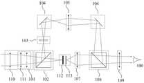
可选地在一具体实例中,共口径物镜中移动组相对于固定组的距离可以为第一距离L1或者第二距离L2,所述移动组相对于所述固定组的距离为第一距离L1时,所述共口径物镜的焦距为f1,对应的物方视场角为θ1,所述移动组相对于所述固定组的距离为第二距离L2时,所述共口径物镜的焦距为f2,对应的物方视场角为θ2,f1和f2不同,θ1和θ2不同。示例的可参考图2,图2为一实施例提供的一种双光多倍率瞄准光学系统的结构示意图,如图所示,本瞄准光学系统中,共口径物镜101包括固定组110和移动组111,固定组110的位置不变,移动组111可移动,相对于固定组110的距离可改变。Optionally, in a specific example, the distance between the moving group and the fixed group in the common-aperture objective lens can be the first distance L1 or the second distance L2, and when the distance between the moving group and the fixed group is the first distance L1 , the focal length of the common-aperture objective lens is f1, and the corresponding object field angle is θ1, and when the distance between the moving group and the fixed group is the second distance L2, the focal length of the common-aperture objective lens is f2, The corresponding object field angle is θ2, f1 and f2 are different, and θ1 and θ2 are different. For an example, please refer to FIG. 2 . FIG. 2 is a schematic structural diagram of a dual-light multi-magnification aiming optical system provided by an embodiment. As shown in the figure, in this aiming optical system, the common-
在实际应用中,可以先根据第二成像子系统中的探测器靶面确定共口径物镜101成像的像高,然后,根据像高设计共口径物镜101的焦距、视场角。具体,根据第二成像子系统中的探测器靶面确定共口径物镜101成像的像高为y′,根据公式y′=f*tan(θ),当y′不变时,焦距f的改变会造成物方视场角θ的改变,本实施例中,两个不同的焦距f1和f2,分别对应着不同的视场角θ1和θ2,因此,当将本瞄准光学系统切换为不同的焦距时,会获得不同大小的视野范围的两种波段光的融合图像,本瞄准光学系统可以通过改变放大倍率从而改变视野大小,优化了狩猎体验。In practical applications, the image height of the common-
另外,由于第一成像子系统和第二成像子系统共用共口径物镜101作为物镜,对于双光通道中由第一中继透镜组105和目镜109构成的系统以及由第二中继透镜组107和目镜109构成的系统而言,光线在出瞳的最大视野θ3为定值,所以整个瞄准光学系统的两个视觉放大率为Γ1=tan(θ3)/tan(θ1)和Γ2=tan(θ3)/tan(θ2),根据以上描述,即可以对目标选择不同的放大倍率进行观测。In addition, since the first imaging subsystem and the second imaging subsystem share the common-
本实施例中,对共口径物镜101中移动组111的移动方式不做限定。可选地,在共口径物镜101的镜筒内设置有多个电磁部,各个所述电磁部分别位于沿所述镜筒轴向的不同位置,在所述移动组的边缘设置有固定结构件,通过所述电磁部对所述固定结构件产生磁吸力,使得所述固定结构件带动所述移动组向所述电磁部移动,使所述移动组移动至该电磁部对应的移动组位置,各个所述电磁部对应的移动组位置相对于所述固定组的距离分别不同。具体地,所述共口径物镜101的镜筒114内沿轴向在所述移动组111的两侧分别设置有电磁部,所述移动组111的边缘设置有具备永磁体特性的固定结构件203;当任一所述电磁部对所述固定结构件203产生磁吸力时,所述固定结构件203带动所述移动组111向该所述电磁部移动,使所述移动组111移动至该电磁部对应的移动组位置。比如,要将移动组111移动至相对于固定组110的距离为第一距离L1的位置时,则控制该位置对应的电磁部产生磁吸力,由于受到磁吸力的作用,移动组111上的固定结构件与移动组111一起会朝向该电磁部运动,从而使移动组111移动至相对于固定组110的距离为第一距离L1的位置。电磁部可以是在通电时具有磁性,产生磁吸力,不通电时不具有磁性,电磁部可采用但不限于电磁线圈。固定结构件为固定移动组111镜片的结构件,可具有永磁体的特性。In this embodiment, there is no limitation on the moving manner of the moving
可选地,可以在镜筒内,在每个电磁部对应的移动组位置处设置有用于固定所述移动组111的限位槽,用于承接移动组111和限定移动组111的位置。本实施例中,对限位槽的结构不做限定。可选地,限位槽可包括第一限位结构件和第二限位结构件,所述第一限位结构件和所述第二限位结构件之间的间隔形成槽。进一步地,所述第一限位结构件比所述第二限位结构件靠近对应的所述电磁部,所述固定结构件仅可正向通过所述第一限位结构件,所述固定结构件可正向以及反向通过所述第二限位结构件,正向是指背离对应的所述电磁部的方向,反向是指朝向对应的所述电磁部的方向。进一步优选地,第一限位结构件设置有传感器,所述传感器用于检测所述第一限位结构件是否与所述固定结构件接触,以当检测到所述第一限位结构件与所述固定结构件接触时控制对应的所述电磁部停止产生磁吸力。Optionally, a limit slot for fixing the moving
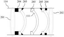
示例地可参考图3,图3为一实施例的共口径物镜的移动组的示意图,如图所示,在共口径物镜101的镜筒114内设置有第一电磁部201和第二电磁部202。在第一电磁部201的一侧设置有第一限位结构件204和第二限位结构件205,以构成与第一电磁部201对应的限位槽,该第一限位结构件204比该第二限位结构件205更靠近第一电磁部201。在第二电磁部202的一侧设置有第一限位结构件204和第二限位结构件205,以构成与第二电磁部202对应的限位槽,该第一限位结构件204比该第二限位结构件205更靠近第二电磁部202。在移动组111的边缘设置有固定结构件203。As an example, reference can be made to Fig. 3, which is a schematic diagram of a moving group of a co-aperture objective lens of an embodiment, as shown in the figure, a first
当第一电磁部201通电时,由于受到磁吸力作用,固定结构件203与移动组111一起朝向第一电磁部201方向运动,通过第二限位结构件205直到与第一限位结构件204接触。第一限位结构件204具有传感器,当探测到与移动组111的固定结构件203接触时,使得第一电磁部201自动断电,此时移动组111由第一限位结构件204和第二限位结构件205共同固定住。其中,固定结构件203不可反向通过第一限位结构件204,第一限位结构件204对固定结构件203起到反向限制的作用。固定结构件203可正向以及反向通过第二限位结构件205,当移动组111需要改变位置时,则另一端的第二电磁部202通电,同时,第一电磁部201一侧的第二限位结构件205通过机构调节不具有反向限制作用,移动组则受到磁吸力作用被吸引到通电的第二电磁部202一侧的限位槽中。示例地可参考图3所示,第一电磁部201可以是电磁线圈,第二电磁部202可以是电磁线圈。第一限位结构件204可以是方形限位结构件,第二限位结构件205可以是三角形限位结构件。When the first
可选地,第一成像子系统包括所述共口径物镜、分光转向元件、转向组件和转向融合元件,所述第二成像子系统包括所述共口径物镜、所述分光转向元件、图像处理装置和所述转向融合元件,所述分光转向元件设置于所述共口径物镜的出光光路上,用于将通过所述共口径物镜进入的物方光线中第一波段光线分出,使第一波段光线经过所述转向组件折转传播方向后入射至所述转向融合元件,以及将通过所述共口径物镜进入的物方光线中第二波段光线分出,使第二波段光线入射至所述图像处理装置;所述图像处理装置用于基于接收到的第二波段光线进行光电转换以及将成像获得的所述第二图像显示,使显示的所述第二图像的光线入射至所述转向融合元件,所述目镜设置于所述转向融合元件的出光一侧,所述转向融合元件用于将所述第一图像的光线和第二图像的光线融合并进入所述目镜。Optionally, the first imaging subsystem includes the common-aperture objective lens, the light-splitting turning element, a turning assembly, and a turning fusion element, and the second imaging subsystem includes the common-aperture objective lens, the light-splitting turning element, and an image processing device and the turning and fusion element, the light splitting and turning element is arranged on the light-emitting optical path of the common-aperture objective lens, and is used to separate the light of the first waveband from the object-side light entering through the common-aperture objective lens, so that the first waveband The light is incident on the steering fusion element after being deflected by the steering assembly, and the second-band light is separated from the object-side light that enters through the common-aperture objective lens, so that the second-waveband light is incident on the image processing device; the image processing device is used to perform photoelectric conversion based on the received light of the second wavelength band and display the second image obtained by imaging, so that the light of the displayed second image enters the steering fusion element , the eyepiece is disposed on the light output side of the steering fusion element, and the steering fusion element is used to fuse the light of the first image and the light of the second image into the eyepiece.
可选地,分光转向元件可以是将通过共口径物镜进入的物方光线中第一波段光线反射/透射,实现将物方光线中第一波段光线分出,以及将物方光线中第二波段光线透射/反射,以将物方光线中第二波段光线分出。示例的可参考图1和图2,图1为一实施例提供的一种双光多倍率瞄准光学系统的结构框图,如图所示,本瞄准光学系统中,作为物镜的共口径物镜101捕获物方光线,使捕获的物方光线入射至分光转向元件102。分光转向元件102设置于共口径物镜101的出光光路上,分光转向元件102将物方光线中第一波段光线反射出,使第一波段光线以与原始传播方向呈90°夹角的方向出射;以及分光转向元件102使物方光线中第二波段光线透射,使第二波段光线沿原始传播方向传播,汇聚至图像处理装置106。Optionally, the light splitting and diverting element can reflect/transmit the first-band light in the object-side light that enters through the common-aperture objective lens, so as to separate the first-waveband light from the object-side light, and divide the second-waveband light from the object-side light Light transmission/reflection to separate the second-band light from the object light. Examples can refer to Fig. 1 and Fig. 2, Fig. 1 is a structural block diagram of a dual-light multi-magnification aiming optical system provided by an embodiment, as shown in the figure, in this aiming optical system, the co-aperture
可选地,图像处理装置106可包括依次连接的光电传感器112、图像处理系统(在图2中未示出)和显示屏113,所述光电传感器112用于基于接收到的第二波段光线进行光电转换,所述图像处理系统用于将获得的成像信息进行处理,所述显示屏113用于将处理后的成像信息以可见光的形式显示。如图2所示,光电传感器112位于分光转向元件102的第二波段光线的出射光路上,且位于共口径物镜101的焦平面上,使得由共口径物镜101捕获的物方光线中第二波段光线能够在光电传感器112上清晰成像。Optionally, the
本实施例中,对光电传感器112的类型不做限定,若第二波段光线为红外光,光电传感器112采用红外传感器。本实施例中,对显示屏113的类型不做限定,优选显示屏113采用微型显示屏,显示屏113显示的图像形式包含但不局限于灰度图像、伪彩色图像或者轮廓图。优选地,在图像处理装置106的显示屏113设置有分划线,在目镜视野中显示屏113上的分划线显现出,根据分划线可以获得被观测物体的相对位置信息。可选地,显示屏113上的分划线可以是十字刻线。In this embodiment, the type of the
优选地,第一成像子系统还可包括标有分划线的透光的分划板103,所述分划板103设置于所述分光转向元件102的第一波段光线的出射光路上,且位于所述共口径物镜101的焦平面上,使得由共口径物镜101捕获的物方光线中第一波段光线能够在分划板103处清晰成像。可参考图1和图2所示,分划板103位于由共口径物镜101经过分光转向元件102对第一波段光线成像的位置,分划板103作为辅助器件,在目镜视野中分划板103上的分划线显现出,对场景中的目标起到定位和测距的作用。可选地,分划板103上的分划线可以是十字刻线。Preferably, the first imaging subsystem may further include a light-transmitting
进一步优选地,第一成像子系统还包括设置于所述分光转向元件102和所述转向融合元件108之间的第一中继透镜组105,所述第一中继透镜组105用于校正由所述分光转向元件102出射的第一波段光线的光束口径和波前。通过第一中继透镜组105将经过分划板103后的第一波段光线成像到转向融合元件108中,通过第一中继透镜组105校正由第一波段光线成像的第一图像的光束口径和波前。Further preferably, the first imaging subsystem further includes a first
所述第二成像子系统还包括设置于所述图像处理装置106和所述转向融合元件108之间的第二中继透镜组107,所述第二中继透镜组107用于将所述图像处理装置106显示的第二图像成像到所述转向融合元件108中,以校正所述第二图像光线的光束口径和波前。The second imaging subsystem also includes a second
由图像处理系统处理后的第二图像以可见光的形式呈现于显示屏113上,在该显示屏113上同时也会显示电子分划线信息,图像和电子分划线经过第二中继透镜组107后与第一成像子系统通道的光线进行融合,能够融合的条件为两个通道的光线入射到转向融合元件108的光束口径大小和波前一致,针对此,优选地,第一中继透镜组105和第二中继透镜组107使到达所述转向融合元件108的所述第一图像光线的光束口径和波前,分别与到达所述转向融合元件108的所述第二图像光线的光束口径和波前一致。两个通道的中继透镜组可以通过设置特定的放大倍率和像差校正实现这一功能。融合的形式可以为第二图像融合进第一成像子系统通道的图像中,包括但不限于以轮廓,伪彩色和灰度图像等形式叠加到第一波段光线图像中。在人眼观测到融合图像中同样包括两个通道的分划线,当两个系统融合较好时,两个十字线完全重合;当融合较差时,需要调整图像处理装置106中显示屏113的图像相对位置,使两个十字线基本重合。The second image processed by the image processing system is presented on the
本实施例中,对第一中继透镜组105、第二中继透镜组107的结构不做限定,第一中继透镜组105、第二中继透镜组107可包括但不限于凸透镜、凹透镜、球面透镜或者非球面透镜中的任意一种或者任意多种的组合。可以根据实际需要对共口径物镜进行光学设计。In this embodiment, the structures of the first
分光转向元件102可以采用但不限于棱镜,比如图2所示采用正方体棱镜,通过其对角面进行分光。转向融合元件108可以采用但不限于棱镜,比如图2所示采用正方体棱镜,通过其对角面将两通道光线汇合。The light splitting and diverting
可选地,转向组件可包括设置于所述分光转向元件102和所述第一中继透镜组105之间的转向元件104,以及设置于所述第一中继透镜组105和所述转向融合元件108之间的转向元件104。可参考图1和图2所示,经过分划板103后的光线被位于所述第一中继透镜组105之前的转向元件104反射,使光线以与原始传播方向为90°夹角的方向传播而入射至第一中继透镜组105,经过第一中继透镜组105后的光线被位于所述第一中继透镜组105之后的转向元件104反射,使光线折转90°传播而入射至转向融合元件108。Optionally, the steering assembly may include a
转向融合元件108将第一图像的光线和第二图像的光线融合并进入目镜109,使两部分图像光线能够以光轴重合的形式入射到目镜109中,最终被人眼100所观测。目镜109将融合后的光线在出瞳处以平行光出射,供用户用眼睛观测,同时,目镜109还起到校正第一成像子系统通道光线的剩余像差和第二成像子系统通道光线的剩余像差的作用。Turning to the
优选地,在所述分划板103的一侧设置有照明器件,所述照明器件用于出射光以照亮所述分划线。在白天时,照明器件不开启即不发光,第一成像子系统中分划板103的十字刻线以灰黑色被人眼所观察到,在夜晚可以开启照明器件即照明器件发出光,照亮分划板103的十字刻线,被照亮的十字刻线以银色显示。Preferably, an illuminating device is provided on one side of the
以上对本发明所提供的一种双光多倍率瞄准光学系统进行了详细介绍。本文中应用了具体个例对本发明的原理及实施方式进行了阐述,以上实施例的说明只是用于帮助理解本发明的方法及其核心思想。应当指出,对于本技术领域的普通技术人员来说,在不脱离本发明原理的前提下,还可以对本发明进行若干改进和修饰,这些改进和修饰也落入本发明权利要求的保护范围内。The above is a detailed introduction to the dual-light multi-magnification collimating optical system provided by the present invention. In this paper, specific examples are used to illustrate the principle and implementation of the present invention, and the descriptions of the above embodiments are only used to help understand the method and core idea of the present invention. It should be pointed out that for those skilled in the art, without departing from the principle of the present invention, some improvements and modifications can be made to the present invention, and these improvements and modifications also fall within the protection scope of the claims of the present invention.
Claims (13)
Translated fromChinesePriority Applications (1)
| Application Number | Priority Date | Filing Date | Title |
|---|---|---|---|
| CN202211226591.5ACN115437136A (en) | 2022-10-09 | 2022-10-09 | A double-light multi-magnification aiming optical system |
Applications Claiming Priority (1)
| Application Number | Priority Date | Filing Date | Title |
|---|---|---|---|
| CN202211226591.5ACN115437136A (en) | 2022-10-09 | 2022-10-09 | A double-light multi-magnification aiming optical system |
Publications (1)
| Publication Number | Publication Date |
|---|---|
| CN115437136Atrue CN115437136A (en) | 2022-12-06 |
Family
ID=84251069
Family Applications (1)
| Application Number | Title | Priority Date | Filing Date |
|---|---|---|---|
| CN202211226591.5APendingCN115437136A (en) | 2022-10-09 | 2022-10-09 | A double-light multi-magnification aiming optical system |
Country Status (1)
| Country | Link |
|---|---|
| CN (1) | CN115437136A (en) |
Citations (8)
| Publication number | Priority date | Publication date | Assignee | Title |
|---|---|---|---|---|
| JP2005274796A (en)* | 2004-03-23 | 2005-10-06 | Fuji Photo Film Co Ltd | Lens device and camera module |
| WO2006113705A2 (en)* | 2005-04-18 | 2006-10-26 | Raytheon Company | Multi-magnification viewing and aiming scope |
| CN101086547A (en)* | 2006-06-09 | 2007-12-12 | 鸿富锦精密工业(深圳)有限公司 | Lens module |
| CN108152973A (en)* | 2017-12-13 | 2018-06-12 | 北京华航无线电测量研究所 | A kind of visible ray and medium-wave infrared Shared aperture complex optics |
| CN111897086A (en)* | 2020-09-01 | 2020-11-06 | 重庆金山医疗器械有限公司 | A zoom structure, zoom objective lens, zoom method and electronic endoscope |
| CN112859322A (en)* | 2021-02-10 | 2021-05-28 | 光速视觉(北京)科技有限公司 | Electronic eyepiece, eyepiece adapter and telescope |
| CN113589502A (en)* | 2021-07-05 | 2021-11-02 | 湖北华中光电科技有限公司 | Large-visual-field visible light and near-infrared light common-path zooming imaging system |
| CN114205505A (en)* | 2021-12-14 | 2022-03-18 | 合肥英睿系统技术有限公司 | Double-light preposed aiming device, adjusting method thereof and aiming system |
- 2022
- 2022-10-09CNCN202211226591.5Apatent/CN115437136A/enactivePending
Patent Citations (8)
| Publication number | Priority date | Publication date | Assignee | Title |
|---|---|---|---|---|
| JP2005274796A (en)* | 2004-03-23 | 2005-10-06 | Fuji Photo Film Co Ltd | Lens device and camera module |
| WO2006113705A2 (en)* | 2005-04-18 | 2006-10-26 | Raytheon Company | Multi-magnification viewing and aiming scope |
| CN101086547A (en)* | 2006-06-09 | 2007-12-12 | 鸿富锦精密工业(深圳)有限公司 | Lens module |
| CN108152973A (en)* | 2017-12-13 | 2018-06-12 | 北京华航无线电测量研究所 | A kind of visible ray and medium-wave infrared Shared aperture complex optics |
| CN111897086A (en)* | 2020-09-01 | 2020-11-06 | 重庆金山医疗器械有限公司 | A zoom structure, zoom objective lens, zoom method and electronic endoscope |
| CN112859322A (en)* | 2021-02-10 | 2021-05-28 | 光速视觉(北京)科技有限公司 | Electronic eyepiece, eyepiece adapter and telescope |
| CN113589502A (en)* | 2021-07-05 | 2021-11-02 | 湖北华中光电科技有限公司 | Large-visual-field visible light and near-infrared light common-path zooming imaging system |
| CN114205505A (en)* | 2021-12-14 | 2022-03-18 | 合肥英睿系统技术有限公司 | Double-light preposed aiming device, adjusting method thereof and aiming system |
Similar Documents
| Publication | Publication Date | Title |
|---|---|---|
| CA2822076C (en) | Active imaging device having field of view and field of illumination with corresponding rectangular aspect ratios | |
| EP2115515B1 (en) | Common-aperture optical system incorporating a light sensor and a light source | |
| CA2838764C (en) | Multiple spectral single image sighting system using single objective lens set | |
| US9494787B1 (en) | Direct view zoom scope with single focal plane and adaptable reticle | |
| CN104020557A (en) | Monocular and quasibinocular transformation observing optical device | |
| KR20160091909A (en) | Telecentric lens | |
| KR101469060B1 (en) | Omnidirectional Optic System | |
| US3173012A (en) | Telescope system for simultaneously viewing two superposed images of the same objectat different magnifications | |
| SE451282B (en) | BINOCULES CONSIDERATION TO VIEW THE SAME PICTURE WITH BADA OGONEN AT THE SAME TIME | |
| US10178372B2 (en) | Long focal length monocular 3D imager | |
| CN112305739B (en) | Infrared dual-band imaging optical system combining common optical path wide and narrow fields of view | |
| CN115437136A (en) | A double-light multi-magnification aiming optical system | |
| US10690892B2 (en) | Telecentric lens | |
| KR102586564B1 (en) | Transmission/reflection hybrid common optical system using off-axis optical system and method for correcting off-axis aberration using the same | |
| CN107688236A (en) | Roll over shaft type astronomical telescope pupil and spectrograph slit monitoring method and its equipment | |
| RU2277254C2 (en) | Device for detecting optical-electronical objects (variants) | |
| KR101608404B1 (en) | Single lens Microscope for three dimensional image | |
| KR20150071420A (en) | LASER Tracking and Pointing Optical System having Pluralized Optical Telescopes | |
| US7466481B2 (en) | Binocular with disparate fields of view | |
| US4568153A (en) | Binocular telescope | |
| US4881796A (en) | Single-aperture multi-spectral reticle projector | |
| CN220288408U (en) | Combined aiming system and optical system thereof | |
| WO2020110233A1 (en) | Set of negative meniscus lenses, wide-angle optical system, imaging device, and projection device | |
| EP4485045A1 (en) | Combined sighting system and optical system thereof | |
| RU2699125C1 (en) | Surveillance device-sights with built-in laser range finder |
Legal Events
| Date | Code | Title | Description |
|---|---|---|---|
| PB01 | Publication | ||
| PB01 | Publication | ||
| SE01 | Entry into force of request for substantive examination | ||
| SE01 | Entry into force of request for substantive examination | ||
| TA01 | Transfer of patent application right | Effective date of registration:20250508 Address after:Building C, International Science and Technology Innovation Center, Bajiaowan Central Innovation Zone, No. 3 Nanchang Street, Yantai Area, China (Shandong) Pilot Free Trade Zone, Yantai City, Shandong Province 264000 Applicant after:YANTAI RAYTRON TECHNOLOGY Co.,Ltd. Country or region after:China Address before:230012 northeast corner of the intersection of Dayu road and xifeihe Road, Xinzhan District, Hefei City, Anhui Province Applicant before:INFIRAY TECHNOLOGIES CO.,LTD. Country or region before:China | |
| TA01 | Transfer of patent application right |