CN115434686A - Method for inhibiting edge-bottom water coning of heterogeneous fault block heavy oil reservoir and application - Google Patents
Method for inhibiting edge-bottom water coning of heterogeneous fault block heavy oil reservoir and applicationDownload PDFInfo
- Publication number
- CN115434686A CN115434686ACN202211153679.9ACN202211153679ACN115434686ACN 115434686 ACN115434686 ACN 115434686ACN 202211153679 ACN202211153679 ACN 202211153679ACN 115434686 ACN115434686 ACN 115434686A
- Authority
- CN
- China
- Prior art keywords
- well
- bottom water
- edge
- heavy oil
- water
- Prior art date
- Legal status (The legal status is an assumption and is not a legal conclusion. Google has not performed a legal analysis and makes no representation as to the accuracy of the status listed.)
- Granted
Links
Images


Classifications
- E—FIXED CONSTRUCTIONS
- E21—EARTH OR ROCK DRILLING; MINING
- E21B—EARTH OR ROCK DRILLING; OBTAINING OIL, GAS, WATER, SOLUBLE OR MELTABLE MATERIALS OR A SLURRY OF MINERALS FROM WELLS
- E21B43/00—Methods or apparatus for obtaining oil, gas, water, soluble or meltable materials or a slurry of minerals from wells
- E21B43/32—Preventing gas- or water-coning phenomena, i.e. the formation of a conical column of gas or water around wells
- E—FIXED CONSTRUCTIONS
- E21—EARTH OR ROCK DRILLING; MINING
- E21B—EARTH OR ROCK DRILLING; OBTAINING OIL, GAS, WATER, SOLUBLE OR MELTABLE MATERIALS OR A SLURRY OF MINERALS FROM WELLS
- E21B43/00—Methods or apparatus for obtaining oil, gas, water, soluble or meltable materials or a slurry of minerals from wells
- E21B43/30—Specific pattern of wells, e.g. optimising the spacing of wells
- G—PHYSICS
- G06—COMPUTING OR CALCULATING; COUNTING
- G06F—ELECTRIC DIGITAL DATA PROCESSING
- G06F30/00—Computer-aided design [CAD]
- G06F30/20—Design optimisation, verification or simulation
- G06F30/23—Design optimisation, verification or simulation using finite element methods [FEM] or finite difference methods [FDM]
- G—PHYSICS
- G06—COMPUTING OR CALCULATING; COUNTING
- G06Q—INFORMATION AND COMMUNICATION TECHNOLOGY [ICT] SPECIALLY ADAPTED FOR ADMINISTRATIVE, COMMERCIAL, FINANCIAL, MANAGERIAL OR SUPERVISORY PURPOSES; SYSTEMS OR METHODS SPECIALLY ADAPTED FOR ADMINISTRATIVE, COMMERCIAL, FINANCIAL, MANAGERIAL OR SUPERVISORY PURPOSES, NOT OTHERWISE PROVIDED FOR
- G06Q50/00—Information and communication technology [ICT] specially adapted for implementation of business processes of specific business sectors, e.g. utilities or tourism
- G06Q50/02—Agriculture; Fishing; Forestry; Mining
- Y—GENERAL TAGGING OF NEW TECHNOLOGICAL DEVELOPMENTS; GENERAL TAGGING OF CROSS-SECTIONAL TECHNOLOGIES SPANNING OVER SEVERAL SECTIONS OF THE IPC; TECHNICAL SUBJECTS COVERED BY FORMER USPC CROSS-REFERENCE ART COLLECTIONS [XRACs] AND DIGESTS
- Y02—TECHNOLOGIES OR APPLICATIONS FOR MITIGATION OR ADAPTATION AGAINST CLIMATE CHANGE
- Y02A—TECHNOLOGIES FOR ADAPTATION TO CLIMATE CHANGE
- Y02A10/00—TECHNOLOGIES FOR ADAPTATION TO CLIMATE CHANGE at coastal zones; at river basins
- Y02A10/40—Controlling or monitoring, e.g. of flood or hurricane; Forecasting, e.g. risk assessment or mapping
Landscapes
- Engineering & Computer Science (AREA)
- Life Sciences & Earth Sciences (AREA)
- Mining & Mineral Resources (AREA)
- Physics & Mathematics (AREA)
- Geology (AREA)
- Theoretical Computer Science (AREA)
- Geochemistry & Mineralogy (AREA)
- General Life Sciences & Earth Sciences (AREA)
- Business, Economics & Management (AREA)
- Fluid Mechanics (AREA)
- Environmental & Geological Engineering (AREA)
- General Physics & Mathematics (AREA)
- Tourism & Hospitality (AREA)
- Geometry (AREA)
- Primary Health Care (AREA)
- Marketing (AREA)
- General Business, Economics & Management (AREA)
- Human Resources & Organizations (AREA)
- General Health & Medical Sciences (AREA)
- Computer Hardware Design (AREA)
- Evolutionary Computation (AREA)
- Strategic Management (AREA)
- General Engineering & Computer Science (AREA)
- Economics (AREA)
- Health & Medical Sciences (AREA)
- Marine Sciences & Fisheries (AREA)
- Animal Husbandry (AREA)
- Agronomy & Crop Science (AREA)
- Investigation Of Foundation Soil And Reinforcement Of Foundation Soil By Compacting Or Drainage (AREA)
- Geophysics And Detection Of Objects (AREA)
Abstract
Translated fromChinese
Description
Translated fromChinese技术领域technical field
本发明属于油气田开发技术领域,具体涉及到一种抑制非均质断块稠油油藏边底水锥进的方法及应用。The invention belongs to the technical field of oil and gas field development, and in particular relates to a method and application for suppressing edge-bottom water coning in heterogeneous fault-block heavy oil reservoirs.
背景技术Background technique
随着常规轻质油储量的减少,断块稠油油藏在非常规能源接替发挥着有力的支持与推动作用。而对于边水活跃的非均质断块稠油油藏,不规则的井网极易引起储层边底水的不均匀推进,不合理的生产制度引起油井与水体之间形成优势通道,油井过早见水进入高含水阶段,最终影响整个断块油藏的采收率。目前对于存在边底水和高渗带的断块稠油油藏,储层纵向及平面上高渗透条带的存在引起平面驱替不均衡,极易造成油藏严重水淹。With the reduction of conventional light oil reserves, fault-block heavy oil reservoirs play a strong role in supporting and promoting the succession of unconventional energy sources. However, for heterogeneous fault-block heavy oil reservoirs with active edge water, irregular well patterns can easily cause uneven advancement of edge and bottom water in the reservoir, and unreasonable production systems cause the formation of dominant channels between oil wells and water bodies. Premature water breakthrough enters the high water cut stage, which ultimately affects the recovery of the entire fault block reservoir. At present, for fault-block heavy oil reservoirs with edge-bottom water and high-permeability zones, the existence of high-permeability strips in the vertical and horizontal planes of the reservoirs will cause unbalanced plane displacement, which will easily cause serious water flooding of the reservoirs.
该类油藏生产油井在步井和生产制度的制定上需要重点考虑以下几点。其一,受高渗带和边底水的影响,底水容易沿高渗带突进,油井含水上升非常迅速;其二,边底水油藏油水分布复杂,在油井见水后含水率上升加快,产油量大幅度下降,严重甚至会导致油井只产水不产油;其三,边底水油藏中剩余油分布形式多样且复杂,生产成本相对较高,非均质性强导致层间矛盾突出,层间干扰较为严重;其四,常规投产效果较差,主要体现为供液较差,底水锥进和边水推进导致油井过早见水,使无水采油时间缩短;其五,断块稠油油藏注采井网不规则,容易导致某些部位注水不奏效,水驱动用程度低。The production wells of this type of reservoir need to focus on the following points in the formulation of well planning and production systems. First, affected by the high permeability zone and edge-bottom water, the bottom water is easy to rush along the high-permeability zone, and the water cut of the oil well rises very rapidly; second, the distribution of oil and water in the edge-bottom water reservoir is complicated, and the water cut rises faster after the oil well breaks through , the oil production will drop sharply, which may even cause oil wells to only produce water but not oil; third, the distribution of remaining oil in edge-bottom water reservoirs is diverse and complex, the production cost is relatively high, and strong heterogeneity leads to formation The conflicts among them are prominent, and interlayer interference is relatively serious; fourth, the effect of conventional production is poor, which is mainly reflected in poor liquid supply, bottom water coning and edge water advancement lead to premature water breakthrough in oil wells, shortening the time for water-free oil recovery; Fifth, the irregular injection-production well pattern in fault-block heavy oil reservoirs may easily lead to ineffective water injection in some parts, and the degree of water driving is low.
影响此类油藏开发的因素主要有边底水规模、油层厚度、纵向非均质性、油水相渗特征、原油粘度等。在油藏开发过程中地层能量下降不大的情况下,边水规模对于单井的生产效果影响不大。随着油层厚度的增加,底水锥进所驱动的原油量增加,油井累积产油量增加。而油水相渗特征的影响主要体现在初期低含水饱和度、油相渗透率高的阶段,中后期随着含水饱和度上升、油相渗透率快速下降后,影响相对减小。Factors affecting the development of such reservoirs mainly include the scale of edge and bottom water, thickness of oil layer, vertical heterogeneity, characteristics of oil-water phase permeability, crude oil viscosity, etc. In the case of little drop in formation energy during reservoir development, the scale of edge water has little effect on the production effect of a single well. With the increase of oil layer thickness, the amount of crude oil driven by bottom water coning increases, and the cumulative oil production of oil wells increases. The influence of oil-water phase permeability characteristics is mainly reflected in the initial stage of low water saturation and high oil phase permeability, and the influence is relatively reduced in the middle and later stages with the increase of water saturation and the rapid decline of oil phase permeability.
针对此类边底水断块油藏开采时含水迅速上升的问题,目前尚未有较好的控水方案,基本上是通过调节井自身的生产制度的方法来抑制含水上升。因此,基于现有的边底水断块油藏开采方式,尝试通过打一口新井来抑制边水入侵、底水锥进速度,为提高边底水非均质断块油藏的采收率提供技术支撑和理论依据。Aiming at the rapid increase of water cut during the exploitation of such edge-bottom water fault block reservoirs, there is no good water control plan at present. Basically, the water cut rise is suppressed by adjusting the production system of the well itself. Therefore, based on the existing mining methods of fault-block reservoirs with edge-bottom water, it is attempted to suppress edge-water intrusion and bottom-water coning speed by drilling a new well, which provides a basis for improving the recovery of heterogeneous fault-block reservoirs with edge-bottom water. Technical support and theoretical basis.
发明内容Contents of the invention
本部分的目的在于概述本发明的实施例的一些方面以及简要介绍一些较佳实施例。在本部分以及本申请的说明书摘要和发明名称中可能会做些简化或省略以避免使本部分、说明书摘要和发明名称的目的模糊,而这种简化或省略不能用于限制本发明的范围。The purpose of this section is to outline some aspects of embodiments of the invention and briefly describe some preferred embodiments. Some simplifications or omissions may be made in this section, as well as in the abstract and titles of this application, to avoid obscuring the purpose of this section, the abstract and titles, and such simplifications or omissions should not be used to limit the scope of the invention.
本发明提供了一种控制非均质断块稠油油藏边底水入侵的开采技术,可以模拟边底水非均质断块稠油油藏水驱生产过程,监测水驱稠油动态开发,预测非均质断块油藏目标井进入高含水阶段时间。其目的在于:通过油藏数值模拟预测目标井进入高含水阶段时间,提出一种在低位置打一口旁井来延缓高位目标井含水上升的新方案,从而抑制断块稠油油藏边底水锥进。。The invention provides a mining technology for controlling edge-bottom water intrusion in heterogeneous fault-block heavy oil reservoirs, which can simulate the water flooding production process of edge-bottom water heterogeneous fault-block heavy oil reservoirs, and monitor the dynamic development of water flooding heavy oil , to predict the time when the target well enters the high water cut stage in the heterogeneous fault block reservoir. The purpose is to predict the time when the target well enters the high water cut stage through numerical simulation of the reservoir, and propose a new plan to drill a side well at a low position to delay the water cut rise of the high target well, thereby suppressing the edge and bottom water of fault block heavy oil reservoirs Cone into. .
鉴于上述和/或现有技术中存在的问题,提出了本发明。In view of the problems mentioned above and/or in the prior art, the present invention is proposed.
因此,本发明的目的是,克服现有技术中的不足,提供一种抑制非均质断块稠油油藏边底水锥进的方法。Therefore, the object of the present invention is to overcome the deficiencies in the prior art and provide a method for suppressing edge-bottom water coning in heterogeneous fault-block heavy oil reservoirs.
为解决上述技术问题,本发明提供了如下技术方案:包括,In order to solve the above technical problems, the present invention provides the following technical solutions: including,
利用CMG数值模拟器建立目标区块的油藏数值模型;Use the CMG numerical simulator to establish the reservoir numerical model of the target block;
根据模型确定目标井和旁井的井位垂向距离、横向距离及生产制度;Determine the vertical distance, lateral distance and production system of the target well and side wells according to the model;
在目标井旁引入旁井实现控制边底水锥进。A side well is introduced next to the target well to control side and bottom water coning.
作为本发明所述的一种优选方案,其中:所述CMG数值模拟器的输入包括,边底水断块稠油油藏目标区块储层地质资料、生产动态资料、测井资料和油层流体物性资料。As a preferred solution of the present invention, wherein: the input of the CMG numerical simulator includes, edge and bottom water fault block heavy oil reservoir target block reservoir geological data, production dynamic data, logging data and reservoir fluid physical data.
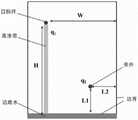
作为本发明所述的一种优选方案,其中:所述目标井与边底水垂向距离为H,与边底水边界的横向距离为为W,产量为q1;所述旁井与边底水的初始垂向距离为L1,与边底水边界的初始横向距离为L2。As a preferred solution of the present invention, wherein: the vertical distance between the target well and the edge-bottom water is H, the lateral distance from the edge-bottom water boundary is W, and the output is q1 ; The initial vertical distance from the bottom water is L1 , and the initial lateral distance from the bottom water boundary is L2 .
作为本发明所述的一种优选方案,其中:所述确定旁井的井位垂向距离,包括,As a preferred solution of the present invention, wherein: the determination of the vertical distance of the well location of the side well includes,
旁井以与目标井相同的产量q1生产;The side well produces with the same outputq1 as the target well;
调整垂向距离L1,使旁井与目标井与边底水距离的比值为0<L1/H<1,通过建立的油藏数值模型,预测目标井含水率超过80%的时间Tw1;Adjust the vertical distance L1 so that the ratio of the distance between the side well and the target well and the edge and bottom water is 0<L1 /H<1, and predict the time Tw1 when the water cut of the target well exceeds 80% through the established numerical model of the reservoir ;
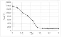
以Tw1为评价指标,绘制横坐标为L1/H、纵坐标为Tw1的优化图版,优选得到旁井与边底水的垂向距离L1*。Taking Tw1 as the evaluation index, drawing the optimization chart with L1 /H on the abscissa and Tw1 on the ordinate, the vertical distance L1 * between the side well and the bottom water is optimally obtained.
作为本发明所述的一种优选方案,其中:所述确定旁井的井位横向距离,包括,As a preferred solution of the present invention, wherein: the determination of the lateral distance of the well location of the side well includes,
旁井以与目标井相同的产量q1生产,与边底水的垂向距离为L1*;The side well produces at the same production rate q1 as the target well, and the vertical distance from the edge and bottom water is L1 *;
调整旁井与边底水边界的横向距离为L2,使旁井与目标井距边界的比值为0<L2/W<1,通过建立的油藏数值模型,预测目标井含水率超过80%的时间Tw2;Adjust the lateral distance between the side well and the edge-bottom water boundary to be L2 , so that the ratio of the distance between the side well and the target well is 0<L2 /W<1. Through the established numerical model of the reservoir, it is predicted that the water cut of the target well exceeds 80 % of time Tw2 ;
以Tw2为评价指标,绘制横坐标为L2/W、纵坐标为Tw2的优化图版,优选旁井与边底水边界的横向距离L2*。Taking Tw2 as the evaluation index, draw the optimization chart with L2 /W on the abscissa and Tw2 on the ordinate, and optimize the lateral distance L2 * between the side well and the edge and bottom water boundary.
作为本发明所述的一种优选方案,其中:所述确定旁井的生产制度,包括,旁井井位垂向距离为L1*、横向距离为L2*;As a preferred solution of the present invention, wherein: the determination of the production system of the side well includes, the vertical distance of the well location of the side well is L1 *, and the lateral distance is L2 *;
调整旁井的产量q2,使其产量与目标井产量比值为0<q2/q1<3,通过建立的油藏数值模型,预测目标井含水率超过80%的时间Tw3;Adjust the production q2 of the side well so that the ratio of production to the production of the target well is 0<q2 /q1 <3, and predict the time Tw3 when the water cut of the target well exceeds 80% through the established numerical model of the reservoir;
以Tw3为评价指标,绘制横坐标为q2/q1、纵坐标为Tw3的优化图版,优选旁井产量q*。Taking Tw3 as the evaluation index, draw an optimization chart with q2 /q1 on the abscissa and Tw3 on the ordinate, and optimize the output q* of the side well.
本发明的再一目的是,克服现有技术中的不足,提供一种抑制非均质断块稠油油藏边底水锥进的方法的应用。Another object of the present invention is to overcome the deficiencies in the prior art and provide the application of a method for suppressing edge-bottom water coning in heterogeneous fault-block heavy oil reservoirs.
为解决上述技术问题,本发明提供了如下技术方案:所述应用包括,油气储层的驱替生产过程以及生产动态分析。In order to solve the above technical problems, the present invention provides the following technical solutions: the application includes the displacement production process of oil and gas reservoirs and production dynamic analysis.
本发明有益效果:Beneficial effects of the present invention:
(1)本发明较为针对具有边底水的非均质断块稠油油藏,由于高渗带的存在导致目标井含水上升迅速,本发明在低构造部位打一口控水旁井,能够更好的将底水引到旁井周围,可以很好的减缓底水突进速度,提高储层平面动用程度,提高原油采收率。(1) The present invention is more aimed at the heterogeneous fault-block heavy oil reservoirs with edge and bottom water. Due to the existence of the high permeability zone, the water content of the target well rises rapidly. If the bottom water is well diverted to the side wells, it can slow down the intrusion speed of the bottom water, improve the degree of horizontal production of the reservoir, and increase the oil recovery rate.
(2)由于原油粘度高、非均质严重、边底水活跃,导致稠油油藏平面动用程度不均,通过控水旁井能够更好的利用底水能量,最大程度动用剩余油,同时又能有效控制边底水入侵速度,降低目标井综合含水,改善其开采效果。(2) Due to the high viscosity of crude oil, serious heterogeneity, and active edge and bottom water, the planar production degree of heavy oil reservoirs is uneven. By controlling water and side wells, the energy of bottom water can be better utilized and the remaining oil can be produced to the greatest extent. It can also effectively control the invasion speed of edge and bottom water, reduce the comprehensive water content of the target well, and improve its mining effect.
(3)本发明在油藏描述的基础上,采用精细网格模型有效模拟具有强边底水的非均质断块稠油油藏生产动态,预测油藏的开发现状及油藏含水上升规律,形成一套控制非均质断块稠油油藏边水入侵的布井方式及开采方案,对此类油藏后期调整具有较高的指导价值。(3) On the basis of reservoir description, the present invention uses a fine grid model to effectively simulate the production dynamics of heterogeneous fault-block heavy oil reservoirs with strong edge and bottom water, and predict the development status of the reservoir and the law of water cut rise in the reservoir , forming a set of well layout and production schemes to control edge water intrusion in heterogeneous fault-block heavy oil reservoirs, which has high guiding value for the later adjustment of such reservoirs.
(4)本发明抛弃了传统调节目标井自身生产制度的观点,有针对性地提出底水旁引的方法,减少高渗带等非均质性引起的驱替平面不均问题。(4) The present invention abandons the traditional point of view of adjusting the production system of the target well itself, and proposes a method of diverting bottom water from the side to reduce the problem of uneven displacement plane caused by heterogeneity such as high permeability zone.
附图说明Description of drawings
为了更清楚地说明本发明实施例的技术方案,下面将对实施例描述中所需要使用的附图作简单地介绍,显而易见地,下面描述中的附图仅仅是本发明的一些实施例,对于本领域普通技术人员来讲,在不付出创造性劳动性的前提下,还可以根据这些附图获得其它的附图。其中:In order to more clearly illustrate the technical solutions of the embodiments of the present invention, the following will briefly introduce the accompanying drawings that need to be used in the description of the embodiments. Obviously, the accompanying drawings in the following description are only some embodiments of the present invention. For Those of ordinary skill in the art can also obtain other drawings based on these drawings without any creative effort. in:
图1为本发明实施例1中边底水非均质断块稠油油藏旁井控水示意图图。Fig. 1 is a schematic diagram of water control in side wells of heavy oil reservoirs with heterogeneous edge and bottom water in fault block heavy oil reservoirs in Example 1 of the present invention.
图2为本发明实施例1中旁井井位垂向距离优选图版。Fig. 2 is an optimized diagram of the vertical distance of the well location of the side well in Example 1 of the present invention.
图3为本发明实施例1中旁井井位横向距离优选图版。Fig. 3 is an optimal diagram of the lateral distance of the side well location in Example 1 of the present invention.
图4为本发明实施例1中旁井产量优选图版。Fig. 4 is an optimized chart of side well production in Example 1 of the present invention.
图5为本发明实施例2中生产井旁引入旁井前后的油藏剩余油分布特征对比图。Fig. 5 is a comparison chart of distribution characteristics of remaining oil in the reservoir before and after introducing side wells beside production wells in Example 2 of the present invention.
具体实施方式detailed description
为使本发明的上述目的、特征和优点能够更加明显易懂,下面结合说明书实施例对本发明的具体实施方式做详细的说明。In order to make the above objects, features and advantages of the present invention more obvious and comprehensible, the specific implementation manners of the present invention will be described in detail below in conjunction with the embodiments of the specification.
在下面的描述中阐述了很多具体细节以便于充分理解本发明,但是本发明还可以采用其他不同于在此描述的其它方式来实施,本领域技术人员可以在不违背本发明内涵的情况下做类似推广,因此本发明不受下面公开的具体实施例的限制。In the following description, a lot of specific details are set forth in order to fully understand the present invention, but the present invention can also be implemented in other ways different from those described here, and those skilled in the art can do it without departing from the meaning of the present invention. By analogy, the present invention is therefore not limited to the specific examples disclosed below.
其次,此处所称的“一个实施例”或“实施例”是指可包含于本发明至少一个实现方式中的特定特征、结构或特性。在本说明书中不同地方出现的“在一个实施例中”并非均指同一个实施例,也不是单独的或选择性的与其他实施例互相排斥的实施例。Second, "one embodiment" or "an embodiment" referred to herein refers to a specific feature, structure or characteristic that may be included in at least one implementation of the present invention. "In one embodiment" appearing in different places in this specification does not all refer to the same embodiment, nor is it a separate or selective embodiment that is mutually exclusive with other embodiments.
实施例1Example 1
本实施例提供了一种抑制非均质断块稠油油藏边底水锥进的方法。This embodiment provides a method for suppressing edge-bottom water coning in heterogeneous fault-block heavy oil reservoirs.
S1:建立目标油藏数值模型;S1: Establish a numerical model of the target reservoir;
以边底水断块稠油油藏目标区块储层地质资料、生产动态资料、测井资料以及油层流体物性资料作为输入,利用CMG数值模拟器建立目标区块的油藏数值模型;Taking the reservoir geological data, production dynamic data, logging data and reservoir fluid physical property data of the target block of the heavy oil reservoir with edge-bottom water fault block as input, the numerical model of the reservoir of the target block is established by using the CMG numerical simulator;
进一步的,储层地质资料包括储层宽度、储层长度、厚度、地层倾角、埋深、温度、压力;Further, the geological data of the reservoir include reservoir width, reservoir length, thickness, formation dip, buried depth, temperature, and pressure;
生产动态资料包括井产量、含水率、井位距离边水距离;Production dynamic data include well production, water cut, distance from well location to edge water;
测井资料包括渗透率,孔隙度、含油饱和度;Logging data include permeability, porosity, oil saturation;
油层流体物性资料包括原油粘度。The physical property data of reservoir fluid include the viscosity of crude oil.
S2:根据模型确定目标井和旁井的井位垂向距离、横向距离及生产制度;S2: Determine the vertical distance, lateral distance and production system of the target well and the side well according to the model;
进一步的,可见图1,展示了本发明边底水非均质断块稠油油藏旁井控水示意图,所述目标井与边底水垂向距离为H,与边底水边界的横向距离为为W,产量为q1;所述旁井与边底水的初始垂向距离为L1,与边底水边界的初始横向距离为L2。Further, as can be seen in Fig. 1, it shows a schematic diagram of water control by wells next to edge-bottom water heterogeneous fault block heavy oil reservoirs of the present invention, the vertical distance between the target well and the edge-bottom water is H, and the horizontal distance from the edge-bottom water boundary is The distance is W, and the output is q1 ; the initial vertical distance between the side well and the edge and bottom water is L1 , and the initial lateral distance from the boundary of the edge and bottom water is L2 .
A1:确定旁井的井位垂向距离;A1: Determine the vertical distance of the well location of the side well;
旁井以与目标井相同的产量q1生产;The side well produces with the same outputq1 as the target well;
调整垂向距离L1,使旁井与目标井与边底水距离的比值为0<L1/H<1,通过建立的油藏数值模型,预测目标井含水率超过80%的时间Tw1;Adjust the vertical distance L1 so that the ratio of the distance between the side well and the target well and the edge and bottom water is 0<L1 /H<1, and predict the time Tw1 when the water cut of the target well exceeds 80% through the established numerical model of the reservoir ;
以Tw1为评价指标,绘制横坐标为L1/H、纵坐标为Tw1的优化图版;Taking Tw1 as the evaluation index, draw an optimization plate whose abscissa is L1 /H and ordinate is Tw1 ;
可见图2,展示了旁井井位垂向距离优选图版,由图可知L1/H越小,抑制含水上升的效果越明显,即,旁井距离边底水越近,降低高位目标井含水的效果越明显,当L1/H大于0.5时,再增大两者比例,其井位对高位目标井含水的影响不大,因此确定控水旁井井位的垂向距离下限为0.5,优选为L1*。It can be seen in Fig. 2, which shows the optimization chart of the vertical distance of the well location of the side well. It can be seen from the figure that the smaller the L1 /H, the more obvious the effect of inhibiting the rise of water cut, that is, the closer the side well is to the edge and bottom water, the lower the water cut of the high-level target well. The effect is more obvious. When L1 /H is greater than 0.5, if the ratio of the two is increased, the well position has little effect on the water content of the high-level target well. Therefore, the lower limit of the vertical distance of the well position next to the water control well is determined to be 0.5. Preferably it is L1 *.
A2:确定旁井的井位横向距离;A2: Determine the lateral distance of the well location of the side well;
旁井以与目标井相同的产量q1生产,与边底水的垂向距离为L1*;The side well produces at the same production rate q1 as the target well, and the vertical distance from the edge and bottom water is L1 *;
调整旁井与边底水边界的横向距离为L2,使旁井与目标井距边界的比值为0<L2/W<1,通过建立的油藏数值模型,预测目标井含水率超过80%的时间Tw2;Adjust the lateral distance between the side well and the edge-bottom water boundary to be L2 , so that the ratio of the distance between the side well and the target well is 0<L2 /W<1. Through the established numerical model of the reservoir, it is predicted that the water cut of the target well exceeds 80 % of time Tw2 ;
以Tw2为评价指标,绘制横坐标为L2/W、纵坐标为Tw2的优化图版;Taking Tw2 as the evaluation index, draw the optimization chart with L2 /W on the abscissa and Tw2 on the ordinate;
可见图3,展示了旁井井位横向距离优选图版,由图可知L2/W小于0.5时,其对高位目标井的含水率影响很小,增大L2/W也并未对高位目标井的含水造成影响;当L2/W大于0.5时,增大L2/W,高位目标井含水率到达Tw2的时间也相对增大,即增大L2可以有效抑制高位目标井的含水;当L2/W到达0.75时,曲线达到峰值,即L2并不是越大越好,旁井并不是距离目标井水平距离越近越好,存在一个最优的位置,使旁井对目标井的含水影响最大,因此确定控水旁井井位的横向距离下限为0.5,最优横向距离L2*为0.75。It can be seen in Fig. 3, which shows the optimization chart of the lateral distance of side wells. It can be seen from the figure that when L2 /W is less than 0.5, it has little effect on the water content of high-level target wells, and increasing L2 /W has no effect on the high-level target wells. The water cut of the well is affected; when L2 /W is greater than 0.5, increasing L2 /W will increase the time for the water cut of the high-level target well to reach Tw2 , that is, increasing L2 can effectively suppress the water cut of the high-level target well ; When L2 /W reaches 0.75, the curve reaches the peak value, that is, the larger L2 is not the better, and the horizontal distance from the side well to the target well is not as good as possible. There is an optimal position so that the side well is opposite to the target well Therefore, the lower limit of the lateral distance to determine the location of the water control side well is 0.5, and the optimal lateral distance L2 * is 0.75.
A3:确定旁井的生产制度;A3: Determine the production system of the side well;
旁井井位垂向距离为L1*、横向距离为L2*;The vertical distance of the side well is L1 *, and the lateral distance is L2 *;
调整旁井的产量q2,使其产量与目标井产量比值为0<q2/q1<3,通过建立的油藏数值模型,预测目标井含水率超过80%的时间Tw3;Adjust the production q2 of the side well so that the ratio of production to the production of the target well is 0<q2 /q1 <3, and predict the time Tw3 when the water cut of the target well exceeds 80% through the established numerical model of the reservoir;
以Tw3为评价指标,绘制横坐标为q2/q1、纵坐标为Tw3的优化图版;Taking Tw3 as the evaluation index, draw an optimization plate with q2 /q1 as the abscissa and Tw3 as the ordinate;
可见图4,展示了旁井产量优选图版,由图可知,当q2/q1小于0.5时,其对高位目标井的含水率影响很小;当0.5<q2/q1<1.3时,曲线对数增加,即增大旁井产量q2可以有效抑制目标井的含水;当1.3<q2/q1时,曲线线性增加,即增大旁井产量q2可以快速抑制目标井的含水,因此,控水旁井井位的产量下限为0.5,优选为q*。It can be seen in Figure 4, which shows the production optimization chart of side wells. It can be seen from the figure that when q2 /q1 is less than 0.5, it has little influence on the water cut of high-level target wells; when 0.5<q2 /q1 <1.3, The logarithm of the curve increases, that is, increasing the production q2 of the side well can effectively suppress the water cut of the target well; when 1.3<q2 /q1 , the curve increases linearly, that is, increasing the production q2 of the side well can quickly suppress the water cut of the target well , therefore, the lower limit of the production of wells beside water control is 0.5, preferably q*.
S3:根据步骤S2得到旁井的垂直、水平位置坐标及生产量,按此指标在目标井旁引入旁井,实现控制边底水锥进。S3: Obtain the vertical and horizontal position coordinates and production volume of the side well according to step S2, and introduce the side well next to the target well according to this index, so as to realize the control of edge and bottom water coning.
实施例2Example 2
参照图5,为本发明另一个实施例,为验证本方法所具有的有益效果,本实施例通过实际应用进行科学论证。Referring to Fig. 5, it is another embodiment of the present invention. In order to verify the beneficial effect of this method, this embodiment conducts scientific demonstration through practical application.
S1:建立目标油藏数值模型;S1: Establish a numerical model of the target reservoir;
目标油藏区块为胜利油田某边底水断块稠油油藏典型区块;The target reservoir block is a typical block of a heavy oil reservoir in a fault block with edge and bottom water in Shengli Oilfield;
该区块的储层地质资料包括:储层尺寸为1650m*1250m,储层倾角为2°、储层最高构造深度1360m、储层厚度5m、储层温度85℃、压力22MPa;The reservoir geological data of this block include: the reservoir size is 1650m*1250m, the reservoir dip angle is 2°, the highest structural depth of the reservoir is 1360m, the reservoir thickness is 5m, the reservoir temperature is 85°C, and the pressure is 22MPa;
井生产动态资料包括:目标井产量为10m3/d;Well production performance data include: target well production is 10m3 /d;
测井资料包括:渗透率为0.944μm2、孔隙度33.7%、含油饱和度;Logging data include: permeability 0.944μm2 , porosity 33.7%, oil saturation;
油层流体物性资料包括:储层温度压力条件下原油粘度为3700mPa·s、The physical property data of the reservoir fluid include: the viscosity of crude oil is 3700mPa·s under the condition of reservoir temperature and pressure,
以上资料作为输入,利用CMG数值模拟器建立该区块的油藏数值模型,设置模型网格数为33×50×5=8250个;The above data are used as input, and the numerical model of the oil reservoir of this block is established by using the CMG numerical simulator, and the number of model grids is set to 33×50×5=8250;
设置地层倾角为2°、顶部深度1360m、网格尺寸25m×25m×1m、孔隙度34%、渗透率1.0μm2;Set the formation dip to 2°, top depth to 1360m, grid size to 25m×25m×1m, porosity to 34%, and permeability to 1.0μm2 ;
高部位目标井位置网格为(10,12),以10m3/d的产量生产,目标井附近高渗通道占据垂直方向三列网格,渗透率为10μm2;The location grid of the target well in the high position is (10, 12), and the production rate is 10m3 /d. The high-permeability channel near the target well occupies three rows of grids in the vertical direction, and the permeability is 10μm2 ;
S2:由于高渗通道的存在,高部位目标井含水上升迅速,为了抑制底水侵入速度,在低部位设计一口控水旁井来调节目标井的生产含水上升。通过改变旁井的位置以及旁井的产量来研究旁井对高部位目标井含水的影响趋势。暂定旁井网格位置为(20,12);S2: Due to the existence of high-permeability channels, the water cut of the target well in the high position rises rapidly. In order to suppress the intrusion rate of bottom water, a water control side well is designed in the low position to adjust the production water cut rise of the target well. By changing the position of the side well and the production of the side well, the influence trend of the side well on the water content of the target well in the high position is studied. The tentative side well grid position is (20, 12);
A1:调整旁井距离底水的垂直距离网格数L1,L1分别取0、4、……、36,H表示高部位目标井距离底水的垂直距离,每次调整后,通过建立的油藏数值模型预测目标井到达高含水时间Tw1;A1: Adjust the grid number L1 of the vertical distance from the side well to the bottom water. L1 is 0, 4, ..., 36 respectively. The reservoir numerical model predicts the target well reaches high water cut time Tw1 ;
以L1/H为横坐标,目标井含水率达80%的时间Tw1为纵坐标绘制图版,优选出最合适的L1*,得出L1/H为0.5以下时降低含水率效果更明显,即最优井位位置(20,28)。Take L1 /H as the abscissa and Tw1 as the ordinate when the water cut of the target well reaches 80% to draw a chart, optimize the most suitable L1 *, and obtain that when L1 /H is less than 0.5, the effect of reducing the water cut is better Obviously, it is the optimal well location (20, 28).
A2:固定控水旁井的垂直方向坐标,即L1始终为20,改变旁井距离边界的水平距离网格数L2,L2分别取1、3、……、21,W表示高部位目标井距离边界的水平距离。每次调整后,通过建立的油藏数值模型预测目标井到达高含水时间Tw2;A2: Fix the vertical coordinates of the side well for water control, that is, L1 is always 20, change the horizontal distance grid number L2 of the side well from the boundary, and L2 is 1, 3, ..., 21 respectively, and W indicates the high position The horizontal distance of the target well from the boundary. After each adjustment, the time Tw2 to reach high water cut in the target well is predicted by the established reservoir numerical model;
以L2/W为横坐标,目标井含水率达80%的时间Tw2为纵坐标绘制图版,得出的图版可以综合得出旁井的最优坐标,为(16,28)。Taking L2 /W as the abscissa and Tw2 as the ordinate when the water content of the target well reaches 80% is drawn as a chart, the obtained chart can be synthesized to obtain the optimal coordinate of the side well, which is (16, 28).
A3:确保旁井坐标为(16,28);高部位目标井产量q1始终为10m3/d。调整旁井的产量q2,q2分别取1m3/d、3m3/d、5m3/d、……、30m3/d,每次调整后,通过建立的油藏数值模型预测目标井到达高含水时间Tw3;A3: Make sure that the coordinates of the side well are (16, 28); the production q1 of the target well at the high position is always 10m3 /d. Adjust the output q2 of the side wells, q2 is respectively 1m3 /d, 3m3 /d, 5m3 /d, ..., 30m3 /d, after each adjustment, predict the target well through the established reservoir numerical model Reach high water content time Tw3;
以q2/q1为横坐标,目标井含水率达80%的时间Tw3为纵坐标绘制图版,优选得到q*的下限为5m3/d。Taking q2 /q1 as the abscissa, and Tw3 as the ordinate when the water cut of the target well reaches 80% is used as the ordinate to draw the chart, and the lower limit of q* is preferably 5m3 /d.
S3:由上述步骤确定针对目标区块的控水旁井应距离边水垂直距离小于475m,与目标井的水平保持125m,建议旁井产量大于5m3/d。S3: From the above steps, it is determined that the vertical distance from the water control side well of the target block should be less than 475m from the side water, and keep 125m from the level of the target well. It is suggested that the production of the side well should be greater than 5m3 /d.
可见图5,展示了在目标井旁引入旁井前后的油藏剩余油分布特征对比,由图可知,位于控水井位下线位置的旁井具有良好的控水效果。再生产相同时间内,旁井的存在极大的增加了油藏的采收率,剩余分布明显减少,油气是提高了旁井与边水、旁井与目标井直井的三角区的驱替效率。It can be seen in Figure 5, which shows the comparison of the distribution characteristics of the remaining oil in the reservoir before and after the introduction of side wells next to the target well. It can be seen from the figure that the side wells located at the lower line of the water control well have good water control effects. During the same period of reproduction, the existence of side wells greatly increases the recovery factor of the reservoir, and the remaining distribution is significantly reduced. The displacement efficiency of oil and gas in the triangular area of side wells and side water, side wells and target well vertical wells is improved.
应说明的是,以上实施例仅用以说明本发明的技术方案而非限制,尽管参照较佳实施例对本发明进行了详细说明,本领域的普通技术人员应当理解,可以对本发明的技术方案进行修改或者等同替换,而不脱离本发明技术方案的精神和范围,其均应涵盖在本发明的权利要求范围当中。It should be noted that the above embodiments are only used to illustrate the technical solutions of the present invention without limitation, although the present invention has been described in detail with reference to the preferred embodiments, those of ordinary skill in the art should understand that the technical solutions of the present invention can be carried out Modifications or equivalent replacements without departing from the spirit and scope of the technical solution of the present invention shall be covered by the claims of the present invention.
Claims (10)
Translated fromChinesePriority Applications (1)
| Application Number | Priority Date | Filing Date | Title |
|---|---|---|---|
| CN202211153679.9ACN115434686B (en) | 2022-09-21 | 2022-09-21 | Method for inhibiting side bottom water coning of heterogeneous broken block heavy oil reservoir and application |
Applications Claiming Priority (1)
| Application Number | Priority Date | Filing Date | Title |
|---|---|---|---|
| CN202211153679.9ACN115434686B (en) | 2022-09-21 | 2022-09-21 | Method for inhibiting side bottom water coning of heterogeneous broken block heavy oil reservoir and application |
Publications (2)
| Publication Number | Publication Date |
|---|---|
| CN115434686Atrue CN115434686A (en) | 2022-12-06 |
| CN115434686B CN115434686B (en) | 2023-08-08 |
Family
ID=84249185
Family Applications (1)
| Application Number | Title | Priority Date | Filing Date |
|---|---|---|---|
| CN202211153679.9AActiveCN115434686B (en) | 2022-09-21 | 2022-09-21 | Method for inhibiting side bottom water coning of heterogeneous broken block heavy oil reservoir and application |
Country Status (1)
| Country | Link |
|---|---|
| CN (1) | CN115434686B (en) |
Citations (16)
| Publication number | Priority date | Publication date | Assignee | Title |
|---|---|---|---|---|
| AU4811485A (en)* | 1984-10-01 | 1986-08-21 | Pfizer Inc. | Modifying the permeability of subterranean formations by injecting phenolic gels |
| US4645003A (en)* | 1985-12-23 | 1987-02-24 | Texaco Inc. | Patterns of horizontal and vertical wells for improving oil recovery efficiency |
| CA1239088A (en)* | 1985-09-30 | 1988-07-12 | Alberta Oil Sands Technology And Research Authority | Method for controlling water coning in oil wells |
| US4945994A (en)* | 1987-12-17 | 1990-08-07 | Standard Alaska Production Company | Inverted wellbore completion |
| CN1560428A (en)* | 2004-02-25 | 2005-01-05 | 石油大学(华东) | A Decision-Making Method for Water Shutoff in Bottom Water Reservoirs |
| US20120205127A1 (en)* | 2011-02-11 | 2012-08-16 | Simon Gittins | Selective displacement of water in pressure communication with a hydrocarbon reservoir |
| CN105631529A (en)* | 2015-10-28 | 2016-06-01 | 中国石油化工股份有限公司 | Edge water gas reservoir water breakthrough time prediction method |
| CN205532555U (en)* | 2016-03-28 | 2016-08-31 | 中国石油天然气股份有限公司 | Well pattern structure |
| CN106837289A (en)* | 2016-12-29 | 2017-06-13 | 中国石油天然气集团公司 | A kind of method and apparatus for determining well location |
| CN108830410A (en)* | 2018-06-05 | 2018-11-16 | 中国石油天然气集团有限公司 | The water breakthrough time prediction technique and device of hyposmosis bottomwater gas field |
| CN110644957A (en)* | 2019-10-10 | 2020-01-03 | 王学忠 | Novel method for improving development effect of super heavy oil edge water reservoir |
| CN111080789A (en)* | 2019-12-26 | 2020-04-28 | 中国石油大学(北京) | Method and device for determining well position of encrypted well in complex fault block oil reservoir exploitation area |
| CN111222243A (en)* | 2020-01-06 | 2020-06-02 | 长江大学 | Method, medium, terminal and device for optimizing well pattern distribution of fractured horizontal well |
| CN114233270A (en)* | 2021-12-14 | 2022-03-25 | 西安石油大学 | Productivity prediction method of horizontal wells in bottom water heavy oil reservoirs |
| CN114580256A (en)* | 2020-12-01 | 2022-06-03 | 中国石油化工股份有限公司 | A well location optimization method for high water-cut oil reservoirs based on seepage feature partitioning |
| CN114810019A (en)* | 2022-04-15 | 2022-07-29 | 中国石油化工股份有限公司 | Development method of imbricated narrow strip edge water heavy oil reservoir |
- 2022
- 2022-09-21CNCN202211153679.9Apatent/CN115434686B/enactiveActive
Patent Citations (16)
| Publication number | Priority date | Publication date | Assignee | Title |
|---|---|---|---|---|
| AU4811485A (en)* | 1984-10-01 | 1986-08-21 | Pfizer Inc. | Modifying the permeability of subterranean formations by injecting phenolic gels |
| CA1239088A (en)* | 1985-09-30 | 1988-07-12 | Alberta Oil Sands Technology And Research Authority | Method for controlling water coning in oil wells |
| US4645003A (en)* | 1985-12-23 | 1987-02-24 | Texaco Inc. | Patterns of horizontal and vertical wells for improving oil recovery efficiency |
| US4945994A (en)* | 1987-12-17 | 1990-08-07 | Standard Alaska Production Company | Inverted wellbore completion |
| CN1560428A (en)* | 2004-02-25 | 2005-01-05 | 石油大学(华东) | A Decision-Making Method for Water Shutoff in Bottom Water Reservoirs |
| US20120205127A1 (en)* | 2011-02-11 | 2012-08-16 | Simon Gittins | Selective displacement of water in pressure communication with a hydrocarbon reservoir |
| CN105631529A (en)* | 2015-10-28 | 2016-06-01 | 中国石油化工股份有限公司 | Edge water gas reservoir water breakthrough time prediction method |
| CN205532555U (en)* | 2016-03-28 | 2016-08-31 | 中国石油天然气股份有限公司 | Well pattern structure |
| CN106837289A (en)* | 2016-12-29 | 2017-06-13 | 中国石油天然气集团公司 | A kind of method and apparatus for determining well location |
| CN108830410A (en)* | 2018-06-05 | 2018-11-16 | 中国石油天然气集团有限公司 | The water breakthrough time prediction technique and device of hyposmosis bottomwater gas field |
| CN110644957A (en)* | 2019-10-10 | 2020-01-03 | 王学忠 | Novel method for improving development effect of super heavy oil edge water reservoir |
| CN111080789A (en)* | 2019-12-26 | 2020-04-28 | 中国石油大学(北京) | Method and device for determining well position of encrypted well in complex fault block oil reservoir exploitation area |
| CN111222243A (en)* | 2020-01-06 | 2020-06-02 | 长江大学 | Method, medium, terminal and device for optimizing well pattern distribution of fractured horizontal well |
| CN114580256A (en)* | 2020-12-01 | 2022-06-03 | 中国石油化工股份有限公司 | A well location optimization method for high water-cut oil reservoirs based on seepage feature partitioning |
| CN114233270A (en)* | 2021-12-14 | 2022-03-25 | 西安石油大学 | Productivity prediction method of horizontal wells in bottom water heavy oil reservoirs |
| CN114810019A (en)* | 2022-04-15 | 2022-07-29 | 中国石油化工股份有限公司 | Development method of imbricated narrow strip edge water heavy oil reservoir |
Non-Patent Citations (1)
| Title |
|---|
| 刘斌;王洪辉;李淑敏;: "小断块边水稠油油藏抑制边水侵入对策研究", 成都理工大学学报(自然科学版), vol. 36, no. 05, pages 97 - 102* |
Also Published As
| Publication number | Publication date |
|---|---|
| CN115434686B (en) | 2023-08-08 |
Similar Documents
| Publication | Publication Date | Title |
|---|---|---|
| CN107664031B (en) | Method for improving recovery efficiency by determining steam flooding well pattern form of horizontal well | |
| CN105822271A (en) | Adjustment method of variable flow line vector of thick-stratum oil deposit | |
| CN109209333B (en) | Shale gas multi-well group efficient mining interval optimization method | |
| RU2439299C1 (en) | Method of oil deposit development | |
| CN114357766B (en) | An optimization design method for overall volume fracturing in long vertical well pattern | |
| Yong et al. | Using cyclic alternating water injection to enhance oil recovery for carbonate reservoirs developed by linear horizontal well pattern | |
| CN115434686B (en) | Method for inhibiting side bottom water coning of heterogeneous broken block heavy oil reservoir and application | |
| Srochviksit et al. | Simulation on heavy oil production from steam-flooding | |
| CN114429085B (en) | A method and system for analyzing fluid potential in fracture-cavity reservoirs | |
| Li et al. | The research on high efficiency water injection development of carbonate rock reservoir in the middle east | |
| CN206309377U (en) | Improved well pattern structure based on rhombus inverse nine-point well pattern | |
| CN116291346A (en) | A Chart Determination Method for Optimizing Foam Control and Flooding System in Vertical Heterogeneous Heavy Oil Reservoir | |
| CN111927413B (en) | Method for determining reasonable bottom hole pressure of constant-pressure injection of polymer injection well | |
| Shao | Research and Field Application on Extreme Subdivision Water Injection Technology for Low Permeability Reservoirs | |
| CN108930530B (en) | W-shaped well network fire flooding development method for multilayer water-flooded oil reservoir | |
| CN113901629A (en) | Method for improving recovery ratio by changing multilayer seven-point method well pattern to develop oil reservoir well pattern | |
| Geng et al. | Research on Refined Water Injection Technology for Medium and High Water Cut Reservoirs in Nanpu 4 Block | |
| Bai et al. | Effect evaluation and influencing factors of stratified water injection in low permeability reservoir | |
| Yang et al. | Development strategy optimization of a giant carbonate reservoir in Middle East under the condition of water channeling along high permeability layers and interlayer crossflow | |
| Han et al. | Study on Dynamic Adjustment Method of Strong Alkali Ternary Compound Flooding in Low Water Cut Period in Block Q | |
| Liu | Study on Comprehensive Adjustment Countermeasures of Weak Alkali ASP Flooding in Low Water Cut Period | |
| Yang et al. | Development Strategy Research and Practice on Reservoir with Big Gas Cap and Narrow Oil Rim in Bohai Bay | |
| Liu et al. | Study on Water-Driving Law and Remaining Oil Distribution Pattern in Ultra-low Permeability Reservoir | |
| Zhang et al. | Numerical Simulation of Injection-Production Coupling Development in Fault-Block Reservoirs | |
| Wang | Optimization and Adjustment Method of Well Pattern in Three Types of Reservoirs in Ultra-high Water Cut Stage |
Legal Events
| Date | Code | Title | Description |
|---|---|---|---|
| PB01 | Publication | ||
| PB01 | Publication | ||
| SE01 | Entry into force of request for substantive examination | ||
| SE01 | Entry into force of request for substantive examination | ||
| GR01 | Patent grant | ||
| GR01 | Patent grant |