CN115429353A - Suturing system - Google Patents
Suturing systemDownload PDFInfo
- Publication number
- CN115429353A CN115429353ACN202211019683.6ACN202211019683ACN115429353ACN 115429353 ACN115429353 ACN 115429353ACN 202211019683 ACN202211019683 ACN 202211019683ACN 115429353 ACN115429353 ACN 115429353A
- Authority
- CN
- China
- Prior art keywords
- needle
- assembly
- seat
- channel
- suturing
- Prior art date
- Legal status (The legal status is an assumption and is not a legal conclusion. Google has not performed a legal analysis and makes no representation as to the accuracy of the status listed.)
- Pending
Links
- 238000009958sewingMethods0.000claimsabstractdescription48
- 230000005540biological transmissionEffects0.000claimsdescription17
- 238000001125extrusionMethods0.000claimsdescription15
- 238000000034methodMethods0.000abstractdescription15
- 230000000149penetrating effectEffects0.000abstract2
- 238000010586diagramMethods0.000description12
- 238000013461designMethods0.000description10
- 238000003780insertionMethods0.000description4
- 230000037431insertionEffects0.000description4
- 230000008602contractionEffects0.000description3
- 238000009434installationMethods0.000description3
- 238000007681bariatric surgeryMethods0.000description2
- 230000002496gastric effectEffects0.000description2
- 239000000463materialSubstances0.000description2
- 208000008589ObesityDiseases0.000description1
- 230000002411adverseEffects0.000description1
- 238000013459approachMethods0.000description1
- 230000009286beneficial effectEffects0.000description1
- 238000004891communicationMethods0.000description1
- 230000007547defectEffects0.000description1
- 230000037213dietEffects0.000description1
- 235000005911dietNutrition0.000description1
- 229940079593drugDrugs0.000description1
- 239000003814drugSubstances0.000description1
- 238000005516engineering processMethods0.000description1
- 238000003306harvestingMethods0.000description1
- 230000003993interactionEffects0.000description1
- 238000012986modificationMethods0.000description1
- 230000004048modificationEffects0.000description1
- 235000020824obesityNutrition0.000description1
- 230000037361pathwayEffects0.000description1
- 238000002360preparation methodMethods0.000description1
- 238000007682sleeve gastrectomyMethods0.000description1
- 238000006467substitution reactionMethods0.000description1
- 238000001356surgical procedureMethods0.000description1
Images


Classifications
- A—HUMAN NECESSITIES
- A61—MEDICAL OR VETERINARY SCIENCE; HYGIENE
- A61B—DIAGNOSIS; SURGERY; IDENTIFICATION
- A61B17/00—Surgical instruments, devices or methods
- A61B17/04—Surgical instruments, devices or methods for suturing wounds; Holders or packages for needles or suture materials
- A61B17/0491—Sewing machines for surgery
- A—HUMAN NECESSITIES
- A61—MEDICAL OR VETERINARY SCIENCE; HYGIENE
- A61B—DIAGNOSIS; SURGERY; IDENTIFICATION
- A61B17/00—Surgical instruments, devices or methods
- A61B17/04—Surgical instruments, devices or methods for suturing wounds; Holders or packages for needles or suture materials
- A61B17/0469—Suturing instruments for use in minimally invasive surgery, e.g. endoscopic surgery
- A—HUMAN NECESSITIES
- A61—MEDICAL OR VETERINARY SCIENCE; HYGIENE
- A61B—DIAGNOSIS; SURGERY; IDENTIFICATION
- A61B17/00—Surgical instruments, devices or methods
- A61B17/04—Surgical instruments, devices or methods for suturing wounds; Holders or packages for needles or suture materials
- A61B2017/0496—Surgical instruments, devices or methods for suturing wounds; Holders or packages for needles or suture materials for tensioning sutures
Landscapes
- Health & Medical Sciences (AREA)
- Life Sciences & Earth Sciences (AREA)
- Surgery (AREA)
- Heart & Thoracic Surgery (AREA)
- Engineering & Computer Science (AREA)
- Biomedical Technology (AREA)
- Nuclear Medicine, Radiotherapy & Molecular Imaging (AREA)
- Medical Informatics (AREA)
- Molecular Biology (AREA)
- Animal Behavior & Ethology (AREA)
- General Health & Medical Sciences (AREA)
- Public Health (AREA)
- Veterinary Medicine (AREA)
- Surgical Instruments (AREA)
Abstract
Description
Translated fromChinese技术领域technical field
本发明涉及医疗器械领域,特别涉及一种缝合系统。The invention relates to the field of medical devices, in particular to a suturing system.
背景技术Background technique
减肥手术在肥胖管理方面已被证实是比饮食、运动和药物治疗更有效的方法。目前常用的术式有胃旁路术、袖状胃切除术、可调胃束带减肥手术等。但是据估计只有不到1%的病态肥胖患者能够接受这些减肥术式。其中的原因包括手术费用高、并发症或不良事件的发生率高。Bariatric surgery has been shown to be more effective than diet, exercise, and medication in the management of obesity. Currently commonly used surgical methods include gastric bypass, sleeve gastrectomy, and adjustable gastric banding. But it is estimated that less than 1% of morbidly obese patients receive these bariatric procedures. Reasons for this include high surgical costs and high rates of complications or adverse events.
专利(CN201780062729)公开了一种具有外部器具通道的内窥镜缝合系统,该技术借助缝合装置可移动穿过组织的针组件,以及与缝合装置相关联使用的第一和第二装置。针组件具有针和缝合线,第一装置可以接纳和抓持针,第二装置可以接合组织并将组织拉回至针的通路中,使得随着针从打开位置移动至闭合位置组织能被针穿刺。该技术中针和缝合线可通过打结或系紧而固定至组织上,或者针可以复位成与针臂接合,并且可以在组织的相邻区域或其他区域内形成其他缝合线圈。打结或系紧的方式可能造成缝线脱离组织而造成缝合失败。Patent (CN201780062729) discloses an endoscopic suturing system with an external instrument channel, a needle assembly movable through tissue by means of a suturing device, and first and second devices used in association with the suturing device. The needle assembly has a needle and a suture, a first device can receive and hold the needle, a second device can engage tissue and pull the tissue back into the pathway of the needle so that the tissue can be drawn by the needle as it moves from an open position to a closed position. puncture. In this technique the needle and suture can be secured to the tissue by knotting or tying, or the needle can be reset into engagement with the needle arm and additional suture loops can be formed in adjacent or other areas of the tissue. Knotting or tying may cause the suture to break away from the tissue and cause the suture to fail.
发明内容Contents of the invention
本发明所要解决的技术问题是提供一种缝合系统,有效的克服了现有技术的缺陷。The technical problem to be solved by the present invention is to provide a suturing system which effectively overcomes the defects of the prior art.
本发明解决上述技术问题的技术方案如下:The technical scheme that the present invention solves the problems of the technologies described above is as follows:
一种缝合系统,包括缝合器头座、缝针座、旋转驱动组件、组织获取组件、接针组件、结扎器和缝针,上述缝合器头座中设有两端贯穿其的获取通道和接针通道,上述旋转驱动组件装于上述缝合器头座上,上述缝针座为弯钩状,其一端通过上述旋转驱动组件连接,上述组织获取组件穿设于上述获取通道中,用于经上述缝合器头座的一端端头外侧获取组织,上述接针组件穿设于上述接针通道中,并可由上述接针通道取出,上述接针组件用于固定或松开上述缝针,上述旋转驱动组件用于驱使上述缝针座转动至缝针座的另一端伸入上述接针通道中,或远离,且在上述缝针座的另一端伸入上述接针通道中时,上述缝针座的另一端端头与固定于上述接针组件处的缝针插接相连,上述结扎器用于经上述接针通道穿过,并在上述缝合器头座的一端端头外对缝线进行结扎。A suturing system, comprising a stapler head base, a suture needle base, a rotary drive assembly, a tissue acquisition assembly, a needle assembly, a ligator and a suture needle, the above-mentioned stapler head base is provided with an acquisition channel and a joint with two ends passing through it. Needle channel, the above-mentioned rotary driving assembly is mounted on the above-mentioned stapler head seat, the above-mentioned sewing needle seat is in the shape of a hook, one end of which is connected by the above-mentioned rotary driving assembly, and the above-mentioned tissue acquisition assembly is installed in the above-mentioned acquisition channel for passing through the above-mentioned The outer side of one end of the stapler head seat acquires tissue, the above-mentioned needle assembly is passed through the above-mentioned needle channel, and can be taken out from the above-mentioned needle channel, the above-mentioned needle assembly is used to fix or loosen the above-mentioned needle, and the above-mentioned rotating drive The assembly is used to drive the above-mentioned needle seat to rotate until the other end of the needle seat extends into the above-mentioned needle-connecting channel, or away from it, and when the other end of the above-mentioned needle seat extends into the above-mentioned needle-connecting channel, the above-mentioned needle seat The other end is plugged and connected with the suture needle fixed at the above-mentioned stitching assembly, and the above-mentioned ligator is used to pass through the above-mentioned stitching channel, and to ligate the suture outside the one end of the stapler head seat.
在上述技术方案的基础上,本发明还可以做如下改进。On the basis of the above technical solutions, the present invention can also be improved as follows.
进一步,上述缝针的一端端部设有插槽,另一端设为针尖,上述缝针座的另一端端部设有与上述插槽适配的接插头,上述插槽具有内外收缩及扩张的弹性,上述缝针座的另一端伸入上述接针通道中时,固定于上述接针组件处的上述缝针的插槽可移动插套于上述缝针座的另一端的接插头外。Further, one end of the above-mentioned sewing needle is provided with a slot, and the other end is set as a needle point, and the other end of the above-mentioned sewing needle seat is provided with a plug that is adapted to the above-mentioned slot, and the above-mentioned slot has internal and external contraction and expansion. Elasticity, when the other end of the above-mentioned needle holder extends into the above-mentioned needle-connecting channel, the slot of the above-mentioned sewing needle fixed at the above-mentioned needle-connector assembly can be moved and inserted into the outside of the socket at the other end of the above-mentioned needle holder.
进一步,上述接针组件包括挤压套管、收缩套管和定位管,上述挤压套管的一端穿设于上述接针通道中,上述收缩套管的一端沿其径向均匀设有多个可内外收缩靠拢或分开的挤压瓣,上述定位管一端与上述收缩套管另一端连接,且其一端伸入上述收缩套管内部,并延伸至多个上述挤压瓣处,上述定位管的一端用于与缝针的针尖插接,上述挤压套管套于上述收缩套管外部,并可相对于上述收缩套管的长轴方向移动,从而使得上述挤压套管的一端沿多个上述挤压瓣的外表面移动,进而使得多个上述挤压瓣向内靠拢或向外分离,多个上述挤压瓣之间的区域形成用于抱紧固定上述缝针的空腔。Further, the needle connector assembly includes an extruded sleeve, a shrink sleeve and a positioning tube, one end of the extruded sleeve is installed in the needle channel, and one end of the shrink sleeve is uniformly arranged with a plurality of Squeeze petals that can be shrunk together or separated from inside and outside. One end of the above-mentioned positioning tube is connected to the other end of the above-mentioned shrinking sleeve, and one end of the above-mentioned shrinking sleeve extends into the inside of the above-mentioned shrinking sleeve, and extends to a plurality of the above-mentioned squeezing petals. One end of the above-mentioned positioning tube It is used for inserting with the needle tip of the sewing needle, the above-mentioned extruding sleeve is sleeved on the outside of the above-mentioned shrinking sleeve, and can move relative to the long axis direction of the above-mentioned shrinking sleeve, so that one end of the above-mentioned extruding sleeve is along the plurality of above-mentioned The outer surface of the extruding flaps moves, thereby making the plurality of extruding flaps close inward or separate outward, and the area between the plurality of extruding flaps forms a cavity for holding and fixing the suture needle.
进一步,上述缝针外周上沿其周向设有定位槽,上述挤压瓣内侧设有用于与上述定位槽嵌合的凸起。Furthermore, positioning grooves are provided on the outer circumference of the needle along its circumference, and protrusions for fitting with the positioning grooves are provided on the inner side of the pressing flap.
进一步,上述旋转驱动组件包括缝合曲柄、传动曲柄和牵拉件,上述缝针座的一端与上述缝合曲柄的一端连接,上述缝合曲柄的另一端设有第一齿轮,该第一齿轮通过第一销轴与上述缝合器头座的一端铰接,上述传动曲柄的一端设有第二齿轮,上述第二齿轮通过第二销轴与上述缝合器头座的一端铰接,且上述第二齿轮与第一齿轮相啮合,上述传动曲柄的另一端与上述牵拉件活动连接,上述牵拉件用于驱使上述传动曲柄绕第二销轴旋转,并带动上述第二齿轮旋转,进而带动上述第一齿轮、缝合曲柄和缝针座旋转。Further, the above-mentioned rotary driving assembly includes a suture crank, a transmission crank and a pulling member, one end of the above-mentioned suture needle holder is connected to one end of the above-mentioned suture crank, and the other end of the above-mentioned suture crank is provided with a first gear, and the first gear passes through the first The pin shaft is hinged with one end of the above-mentioned stapler head seat, and one end of the above-mentioned transmission crank is provided with a second gear, and the above-mentioned second gear is hinged with one end of the above-mentioned stapler head seat through the second pin shaft, and the above-mentioned second gear is connected with the first The gears are meshed, and the other end of the above-mentioned transmission crank is flexibly connected with the above-mentioned pulling member, and the above-mentioned pulling member is used to drive the above-mentioned transmission crank to rotate around the second pin shaft, and drive the above-mentioned second gear to rotate, and then drive the above-mentioned first gear, The suture crank and needle holder rotate.
进一步,上述牵拉件为杆状构件,其朝向上述缝合器头座的另一端延伸。Further, the pulling member is a rod-shaped member extending toward the other end of the stapler head base.
进一步,上述缝合器头座中设有两端贯穿其的操作通道,上述牵拉件穿过上述操作通道,上述获取通道位于上述操作通道和接针通道之间。Further, the head base of the stapler is provided with an operation channel with two ends passing through it, the pulling member passes through the operation channel, and the acquisition channel is located between the operation channel and the needle receiving channel.
进一步,上述缝合器头座的一端端部的一侧突出设有朝向其一端延伸的条形座体,上述缝合曲柄的一端通过第一销轴与上述条形座体铰接,上述传动曲柄的一端通过第二销轴与上述条形座体铰接。Further, one side of one end of the head seat of the stapler is protrudingly provided with a bar-shaped seat extending toward one end thereof, one end of the above-mentioned suture crank is hinged to the above-mentioned bar-shaped seat through a first pin shaft, and one end of the above-mentioned transmission crank It is hinged with the above-mentioned bar-shaped seat body through the second pin shaft.
进一步,还包括导管,上述导管的一端与上述缝合器头座的另一端连接,上述获取通道和接针通道与上述导管内腔贯通。Further, it also includes a catheter, one end of the catheter is connected to the other end of the stapler head base, and the acquisition channel and the needle receiving channel communicate with the inner cavity of the catheter.
本发明的有益效果是:结构设计合理,操作使用方便,缝合过程置物数量少,更佳快速。The beneficial effects of the present invention are: reasonable structural design, convenient operation and use, fewer objects to be placed in the suturing process, and more quickly.
附图说明Description of drawings
图1为本发明的缝合系统的结构示意图;Fig. 1 is the structural representation of suturing system of the present invention;
图2为本发明的缝合系统中缝针座闭合待接针时的结构示意图一;Fig. 2 is a structural schematic diagram 1 when the needle holder is closed and the needle is to be connected in the suturing system of the present invention;
图3为本发明的缝合系统中缝针座闭合接针时的结构示意图二;Fig. 3 is a structural schematic diagram II when the needle holder closes the stitches in the suturing system of the present invention;
图4为本发明的缝合系统中缝针座闭合接针时的结构示意图三;Fig. 4 is a structural schematic diagram 3 when the needle holder closes the stitches in the suturing system of the present invention;
图5为本发明的缝合系统中缝针座闭合后接针完成的结构示意图;Fig. 5 is a schematic diagram of the structure of the stitching after the needle holder is closed in the suturing system of the present invention;
图6为本发明的缝合系统中接针完毕后缝针座打开时的结构示意图;Fig. 6 is a schematic diagram of the structure of the suturing system when the needle holder is opened after the stitching is completed;
图7为本发明的缝合系统中接针完毕后缝针座打开后的结构示意图;Fig. 7 is a schematic diagram of the structure of the suturing system of the present invention after the needle holder is opened after the stitching is completed;
图8为本发明的缝合系统中缝针前获取组织时的结构示意图一;Fig. 8 is a structural schematic diagram 1 when the tissue is obtained before the suturing needle in the suturing system of the present invention;
图9为本发明的缝合系统中缝针前获取组织时的结构示意图二;Fig. 9 is a schematic diagram of the second structure when the tissue is obtained before the suturing needle in the suturing system of the present invention;
图10为本发明的缝合系统中缝针穿刺后缝合的结构示意图一;Fig. 10 is a structural schematic diagram 1 of suturing after needle puncture in the suturing system of the present invention;
图11为本发明的缝合系统中缝针穿刺后缝合的结构示意图二;Fig. 11 is a structural schematic diagram II of suturing after needle puncture in the suturing system of the present invention;
图12为本发明的缝合系统中缝针穿刺后缝合的结构示意图三;Fig. 12 is a schematic diagram of the third structure of suturing after needle puncture in the suturing system of the present invention;
图13为本发明的缝合系统中缝合完毕后缝针座打开时的结构示意图;Fig. 13 is a schematic diagram of the structure of the suturing system when the needle seat is opened after suturing is completed;
图14为本发明的缝合系统中缝合完毕后组织获取组件释放组织后的结构示意图;Fig. 14 is a schematic structural view of the tissue acquisition component after the tissue is released in the suturing system of the present invention after suturing is completed;
图15为本发明的缝合系统中接针组件的结构示意图;Fig. 15 is a schematic structural view of the needle assembly in the suturing system of the present invention;
图16为本发明的缝合系统中旋转驱动组件的结构示意图。Fig. 16 is a schematic structural view of the rotary drive assembly in the suturing system of the present invention.
附图中,各标号所代表的部件列表如下:In the accompanying drawings, the list of parts represented by each label is as follows:
1、缝合器头座;2、缝针座;3、旋转驱动组件;4、组织获取组件;5、接针组件;6、缝针;11、条形座体;21、接插头;31、缝合曲柄;32、传动曲柄;33、牵拉件;51、挤压套管;52、收缩套管;53、定位管;61、定位槽;311、第一齿轮;321、第二齿轮;521、挤压瓣。1. Stapler head base; 2. Needle base; 3. Rotary drive component; 4. Tissue acquisition component; 5. Needle connector component; 6. Needle; 11. Strip seat body; Suture crank; 32, transmission crank; 33, pulling member; 51, extrusion sleeve; 52, shrink sleeve; 53, positioning tube; 61, positioning slot; 311, first gear; 321, second gear; 521 , Squeeze flap.
具体实施方式detailed description
以下结合附图对本发明的原理和特征进行描述,所举实例只用于解释本发明,并非用于限定本发明的范围。The principles and features of the present invention are described below in conjunction with the accompanying drawings, and the examples given are only used to explain the present invention, and are not intended to limit the scope of the present invention.
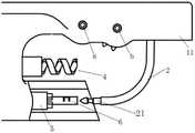
实施例:如图1所示,本实施例的缝合系统包括缝合器头座1、缝针座2、旋转驱动组件3、组织获取组件4、接针组件5、结扎器和缝针6,上述缝合器头座1中设有两端贯穿其的获取通道(图中e指代)和接针通道(图中f指代),上述旋转驱动组件3装于上述缝合器头座1上,上述缝针座2为弯钩状,其一端通过上述旋转驱动组件3连接,上述组织获取组件4穿设于上述获取通道中,用于经上述缝合器头座1的一端端头外侧获取组织,上述接针组件5穿设于上述接针通道中,并可由上述接针通道取出,上述接针组件5用于固定或松开上述缝针6,上述旋转驱动组件3用于驱使上述缝针座2转动至缝针座2的另一端伸入上述接针通道中,或远离,且在上述缝针座2的另一端伸入上述接针通道中时,上述缝针座2的另一端端头与固定于上述接针组件5处的缝针6插接相连,上述结扎器用于经上述接针通道穿过,并在上述缝合器头座1的一端端头外对缝线进行结扎。Embodiment: As shown in Figure 1, the suturing system of this embodiment includes a
手术过程如下:The surgical procedure is as follows:
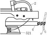
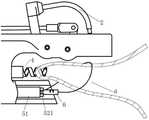
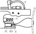
初始状态下,缝针座2打开(也就是缝针座2的另一端位于接插通道外,并远离接插通道,如图1所示,组织获取组件4及接针组件5分别穿设于对应的通道中,并且,缝针6此时是在接针组件5处固定,并连接有缝线图中d指代),手术过程中,通过旋转驱动组件3驱使缝针座2转动至其另一端伸入接针通道中(如图2所示),此时,缝针座2处于闭合状态,操作接针组件5在接针通道中朝向缝合器头座1的一端推进移动,并带动缝针6移动至与缝针座2的另一端端头插接相连(接针完成,如图3所示),接下来,在内窥镜的配合下,操作缝合器头座1进入腔内,之后,操作接针组件5松开缝针6(如图4、5所示),并操作旋转驱动组件3带动缝针座2转动“打开”(如图6、7所示),为后面的缝合做准备。缝合时,操作组织获取组件4经获取通道伸出至抵靠组织(如图8所示,c指代组织),然后操作组织获取组件4移动回位,将组织拉至靠近获取通道,此时,组织位于缝针座2的旋转闭合的区域内(也就是处于缝合区域内,如图9所示),操作旋转驱动组件3带动缝针座2再次旋转闭合(也就是缝合过程),缝线及缝针6随缝针座2一起穿过组织,同时,缝针6进入接针通道中(如图10所示),操作接针组件5再次与缝针6固定住(如图11、12所示),然后操作接针组件5后退,使得缝针6与缝针座2脱离(由于缝针6被接针组件5固定,因此,在缝针座2转动过程中缝针座2因仅与缝针6接插配合,因此,缝针座2会与缝针6脱离,如图13所示),接下来,操作旋转驱动组件3带动缝针座2转动“打开”,接下来,如需多次缝合,则按上述步骤反复多次缝合即可,但需要注意的是,每次缝合时,需操作缝合器头座1微调角度,使得每次缝针座2从组织的外部实现接针,并从组织缝合处穿刺然后完成缝合过程,整个缝合过程完毕后,接针组件5释放缝针6(缝线的一端连接缝针,另一端自接针通道穿出体外),组织获取组件4释放组织(如图14所示),然后撤出接针组件5,在体外将线头拉紧,使得缝针6抵靠于组织外表面,并将外露的缝线与结扎器连接,并将结扎器穿入接针通道中,然后,对缝线另一端在组织外表面处进行打结,打结完毕后缝线在接头附近剪断即可,最后,撤出缝合系统,整个缝合系统结构设计合理,操作使用方便,缝合过程置物数量少,更佳快速。In the initial state, the
需要补充说明的是:缝针座2与缝针6在配合完成缝合过程中,每缝合一次,缝针6均要在穿刺组织后与接针组件5连接固定,然后接针组件5带着缝针6后退,使得缝针6脱离缝针座2,然后操作旋转驱动组件3使得缝针座2旋转打开后,下一次缝针时,自组织的外部完成接针,并在穿刺缝合后完成脱针,这样的缝合过程与现有的缝合方式不同,不会造成缝线脱离组织而导致缝合失败。What needs to be added is: when the
作为一种优选的实施方式,上述缝针6的一端端部设有插槽,另一端设为针尖,上述缝针座2的另一端端部设有与上述插槽适配的接插头21,上述插槽具有内外收缩及扩张的弹性,上述缝针座2的另一端伸入上述接针通道中时,固定于上述接针组件5处的上述缝针6的插槽可移动插套于上述缝针座2的另一端的接插头21外。As a preferred embodiment, one end of the above-mentioned
上述实施方案中,接插头21与插槽的连接为挤入式插接配合,具体的,当缝针座2的另一端伸入接针通道后,操作接针组件5朝向缝针座2另一端推进,直至接插头21逐渐挤入插槽中,然后,在操作接针组件5释放(松开)缝针6后,即可在固定住缝针6,在后续缝针座2旋转打开过程中,即可使得缝针座2带出缝针6,以便进行后续的缝合操作,接插头21与插槽的配合结构设计简单,插接即可。In the above-mentioned embodiment, the connection between the
作为一种优选的实施方式,如图15所示,上述接针组件5包括挤压套管51、收缩套管52和定位管53,上述挤压套管51的一端穿设于上述接针通道中,上述收缩套管52的一端沿其径向均匀设有多个可内外收缩靠拢或分开的挤压瓣521,上述定位管53一端与上述收缩套管52另一端连接,且其一端伸入上述收缩套管52内部,并延伸至多个上述挤压瓣521处,上述定位管53的一端用于与缝针6的针尖插接,上述挤压套管51套于上述收缩套管52外部,并可相对于上述收缩套管52的长轴方向移动,从而使得上述挤压套管51的一端沿多个上述挤压瓣521的外表面移动,进而使得多个上述挤压瓣521向内靠拢或向外分离,多个上述挤压瓣521之间的区域形成用于抱紧固定上述缝针6的空腔。As a preferred embodiment, as shown in Figure 15, the above-mentioned
上述实施方案中,在缝针6的针尖伸入多个挤压瓣521后,并将针尖插入定位管53的一端端口内,接下来,操作挤压套管51相对于收缩套管52移动,并对挤压瓣521产生向内的靠拢挤压作用力,即可将缝针6抱紧固定(完成初始状态下缝针座2接针前的缝针6安装),当缝针座2转动至一端伸入接针通道后,操作挤压套管51及收缩套管52带着缝针6同步推进靠近缝针座2,直至缝针座2与缝针6的尾端(远离针尖的一端)插接,之后,操作挤压套管51和定位管53相对于收缩套管52移动,使得挤压瓣521外露释放,从而释放(松开)缝针6,在该状态下,转动缝针座2打开即可带出缝针6,在一次穿刺组织后,缝针6伸入接针通道,然后操作接针组件5靠近缝针,缝针6的针尖再次插入定位管53的一端端口内,并推动挤压套管51迫使挤压瓣521合拢,使得挤压瓣521包裹缝针6,然后整个接针组件5设计简单,操作挤压套管51相对于收缩套管52移动,并对挤压瓣521产生向内的靠拢挤压作用力,即可将缝针6再次抱紧固定,整个接针组件5设计比较合理,操作使用方便、快捷。In the above-mentioned embodiment, after the needle point of the suture needle 6 is extended into a plurality of extrusion valves 521, and the needle point is inserted into one end port of the positioning tube 53, then the extrusion sleeve 51 is operated to move relative to the contraction sleeve 52, And the extrusion flap 521 generates an inward squeezing force, so that the needle 6 can be tightly hugged and fixed (the installation of the needle 6 before the needle holder 2 is connected in the initial state is completed), when the needle holder 2 rotates After one end is stretched into the needle channel, operate the extrusion sleeve 51 and the shrink sleeve 52 to bring the needle 6 and advance synchronously close to the needle holder 2 until the tail end of the needle holder 2 and the needle 6 (the end far away from the needle tip) ) insertion, after that, operate the extrusion sleeve 51 and the positioning tube 53 to move relative to the shrink sleeve 52, so that the extrusion flap 521 is exposed and released, thereby releasing (releasing) the sewing needle 6, in this state, rotating the sewing needle Seat 2 can be opened to take out suture needle 6, after puncturing the tissue once, suture needle 6 extends into the needle channel, and then operates needle assembly 5 to approach the suture needle, and the needle tip of suture needle 6 is inserted into one end port of positioning tube 53 again , and push the extrusion sleeve 51 to force the extrusion flap 521 to close up, so that the extrusion flap 521 wraps the sewing needle 6, and then the design of the entire needle assembly 5 is simple, and the operation extrusion sleeve 51 moves relative to the shrink sleeve 52, and the The extrusion flap 521 generates an inward squeezing force, which can hold the sewing needle 6 tightly and fix it again. The design of the
需要补充说明的是:上述挤压套管51的外径与接针通道的内径接近或一致,二者之间孔隙较小。It should be added that: the outer diameter of the extruded
作为一种优选的实施方式,上述缝针6外周上沿其周向设有定位槽61,上述挤压瓣521内侧设有用于与上述定位槽61嵌合的凸起(图中m指代)。As a preferred embodiment, a
上述实施方案中,在缝针6被挤压瓣521抱紧后,挤压瓣521内侧的凸起嵌入缝针6外周的定位槽61中,从而使得在操作缝针座2转动打开“拔针”时,凸起会对缝针6起到轴向限位的作用,避免缝针6也被拔出。In the above-mentioned embodiment, after the
作为一种优选的实施方式,如图16所示,上述旋转驱动组件3包括缝合曲柄31、传动曲柄32和牵拉件33,上述缝针座2的一端与上述缝合曲柄31的一端连接,上述缝合曲柄31的另一端设有第一齿轮311,该第一齿轮311通过第一销轴与上述缝合器头座1的一端铰接,上述传动曲柄32的一端设有第二齿轮321,上述第二齿轮321通过第二销轴与上述缝合器头座1的一端铰接,且上述第二齿轮321与第一齿轮311相啮合,上述传动曲柄32的另一端与上述牵拉件33活动连接,上述牵拉件33用于驱使上述传动曲柄32绕第二销轴旋转,并带动上述第二齿轮321旋转,进而带动上述第一齿轮311、缝合曲柄31和缝针座2旋转。As a preferred embodiment, as shown in Figure 16, the above-mentioned rotary drive assembly 3 includes a suture crank 31, a transmission crank 32 and a pulling member 33, one end of the above-mentioned suture needle holder 2 is connected with one end of the above-mentioned suture crank 31, and the above-mentioned The other end of sewing crank 31 is provided with first gear 311, and this first gear 311 is hinged with one end of above-mentioned stapler head seat 1 by first bearing pin, and one end of above-mentioned driving crank 32 is provided with second gear 321, and above-mentioned second The gear 321 is hinged with one end of the above-mentioned stapler head seat 1 through the second pin shaft, and the above-mentioned second gear 321 is meshed with the first gear 311, and the other end of the above-mentioned transmission crank 32 is movably connected with the above-mentioned pulling member 33, and the above-mentioned pulling The pulling member 33 is used to drive the above-mentioned transmission crank 32 to rotate around the second pin shaft, and drive the above-mentioned second gear 321 to rotate, and then drive the above-mentioned first gear 311 , the suture crank 31 and the needle holder 2 to rotate.
上述实施方案中,在牵拉件33带动传动曲柄32旋转(摆转)过程,第二齿轮321旋转,并带动与之啮合的第一齿轮311旋转,从而带动缝合曲柄31和缝针座2同步旋转(摆转),具体地,牵拉件33朝向缝合器头座1的一端推进时,缝针座2旋转打开,在朝向反方向牵拉时,缝针座2旋转闭合,并使端部伸入接针通道中,整个旋转驱动组件3设计简单、合理,操作比较方便。In the above-mentioned embodiment, in the process of driving the transmission crank 32 to rotate (swing) by the pulling
本实施例中,缝合曲柄31为长直的构件,其上沿其长度方向设有延伸至其另一端的贯穿缺口,传动曲柄32穿过该贯穿缺口,并在旋转动作时在该贯穿缺口中摆转。In this embodiment, the suture crank 31 is a long and straight member, which is provided with a through gap extending to the other end along its length direction, and the transmission crank 32 passes through the through gap, and is in the through gap during rotation. swing.
本实施例中,上述牵拉件33采用杆状构件,其朝向上述缝合器头座1的另一端延伸,形状设计合理,方便从体外远端施加牵拉力,当然,牵拉件33也可以是一端与传动曲柄32铰接,另一端连接推拉杆或金属丝线。In this embodiment, the above-mentioned pulling
作为一种优选的实施方式,上述缝合器头座1中设有两端贯穿其的操作通道,上述牵拉件33穿过上述操作通道,上述获取通道位于上述操作通道和接针通道之间。As a preferred embodiment, the
上述实施方案中,操作通道的设计使得牵拉件33自其中穿过,不外漏,避免操作牵拉过程对创口造成影响,此外,由于获取通道位于上述操作通道和接针通道之间,组织在获取后能够有效的拉至缝针座2的缝合区域内,结构设计比较合理,操作顺畅。In the above-mentioned embodiment, the operation channel is designed so that the pulling
作为一种优选的实施方式,上述缝合器头座1的一端端部的一侧突出设有朝向其一端延伸的条形座体11,上述缝合曲柄31的一端通过第一销轴与上述条形座体11铰接,上述传动曲柄32的一端通过第二销轴与上述条形座体11铰接。As a preferred embodiment, one side of one end of the above-mentioned
上述实施方案中,条形座体11的设计利于缝合曲柄31和传动曲柄32的安装,一般地,第一销轴和第二销轴可以装配于条形座体11的同一侧侧端,也可以在条形座体11中间开一个沿其长度方向的条形贯通槽,将第一销轴和第二销轴装配于通槽的两侧槽壁之间,缝合曲柄31和传动曲柄32的部分伸入该条形贯通槽中,两个齿轮完全隐藏在该条形贯通槽中。In the above-mentioned embodiment, the design of the bar-shaped
当然,第一销轴和第二销轴可以等同替换为涡杆和带有轴的涡轮,该涡轮涡杆结构可以传递大力矩,并且有自锁功能,可使手柄结构简化。Certainly, the first pin shaft and the second pin shaft can be equivalently replaced by a worm gear and a turbine with a shaft. The worm gear structure can transmit a large torque and has a self-locking function, which can simplify the handle structure.
作为一种优选的实施方式,还包括导管,上述导管的一端与上述缝合器头座1的另一端连接,上述获取通道和接针通道与上述导管内腔贯通。As a preferred embodiment, it also includes a catheter, one end of the catheter is connected to the other end of the
上述实施方案中,导管的设计可以使得旋转驱动组件3、组织获取组件4和接针组件5均经导管内部穿出,不会外漏,操作更安全。In the above embodiment, the design of the catheter can make the
在本发明的描述中,需要理解的是,术语“中心”、“纵向”、“横向”、“长度”、“宽度”、“厚度”、“上”、“下”、“前”、“后”、“左”、“右”、“竖直”、“水平”、“顶”、“底”“内”、“外”、“顺时针”、“逆时针”、“轴向”、“径向”、“周向”等指示的方位或位置关系为基于附图所示的方位或位置关系,仅是为了便于描述本发明和简化描述,而不是指示或暗示所指的装置或元件必须具有特定的方位、以特定的方位构造和操作,因此不能理解为对本发明的限制。In describing the present invention, it should be understood that the terms "center", "longitudinal", "transverse", "length", "width", "thickness", "upper", "lower", "front", " Back", "Left", "Right", "Vertical", "Horizontal", "Top", "Bottom", "Inner", "Outer", "Clockwise", "Counterclockwise", "Axial", The orientation or positional relationship indicated by "radial", "circumferential", etc. is based on the orientation or positional relationship shown in the drawings, and is only for the convenience of describing the present invention and simplifying the description, rather than indicating or implying the referred device or element Must be in a particular orientation, be constructed in a particular orientation, and operate in a particular orientation, and therefore should not be construed as limiting the invention.
此外,术语“第一”、“第二”仅用于描述目的,而不能理解为指示或暗示相对重要性或者隐含指明所指示的技术特征的数量。由此,限定有“第一”、“第二”的特征可以明示或者隐含地包括至少一个该特征。在本发明的描述中,“多个”的含义是至少两个,例如两个,三个等,除非另有明确具体的限定。In addition, the terms "first" and "second" are used for descriptive purposes only, and cannot be interpreted as indicating or implying relative importance or implicitly specifying the quantity of indicated technical features. Thus, the features defined as "first" and "second" may explicitly or implicitly include at least one of these features. In the description of the present invention, "plurality" means at least two, such as two, three, etc., unless otherwise specifically defined.
在本发明中,除非另有明确的规定和限定,术语“安装”、“相连”、“连接”、“固定”等术语应做广义理解,例如,可以是固定连接,也可以是可拆卸连接,或成一体;可以是机械连接,也可以是电连接;可以是直接相连,也可以通过中间媒介间接相连,可以是两个元件内部的连通或两个元件的相互作用关系,除非另有明确的限定。对于本领域的普通技术人员而言,可以根据具体情况理解上述术语在本发明中的具体含义。In the present invention, unless otherwise clearly specified and limited, terms such as "installation", "connection", "connection" and "fixation" should be understood in a broad sense, for example, it can be a fixed connection or a detachable connection , or integrated; it may be mechanically connected or electrically connected; it may be directly connected or indirectly connected through an intermediary, and it may be the internal communication of two components or the interaction relationship between two components, unless otherwise specified limit. Those of ordinary skill in the art can understand the specific meanings of the above terms in the present invention according to specific situations.
在本发明中,除非另有明确的规定和限定,第一特征在第二特征“上”或“下”可以是第一和第二特征直接接触,或第一和第二特征通过中间媒介间接接触。而且,第一特征在第二特征“之上”、“上方”和“上面”可是第一特征在第二特征正上方或斜上方,或仅仅表示第一特征水平高度高于第二特征。第一特征在第二特征“之下”、“下方”和“下面”可以是第一特征在第二特征正下方或斜下方,或仅仅表示第一特征水平高度小于第二特征。In the present invention, unless otherwise clearly specified and limited, the first feature may be in direct contact with the first feature or the first and second feature may be in direct contact with the second feature through an intermediary. touch. Moreover, "above", "above" and "above" the first feature on the second feature may mean that the first feature is directly above or obliquely above the second feature, or simply means that the first feature is higher in level than the second feature. "Below", "beneath" and "beneath" the first feature may mean that the first feature is directly below or obliquely below the second feature, or simply means that the first feature is less horizontally than the second feature.
在本说明书的描述中,参考术语“一个实施例”、“一些实施例”、“示例”、“具体示例”、或“一些示例”等的描述意指结合该实施例或示例描述的具体特征、结构、材料或者特点包含于本发明的至少一个实施例或示例中。在本说明书中,对上述术语的示意性表述不必须针对的是相同的实施例或示例。而且,描述的具体特征、结构、材料或者特点可以在任一个或多个实施例或示例中以合适的方式结合。此外,在不相互矛盾的情况下,本领域的技术人员可以将本说明书中描述的不同实施例或示例以及不同实施例或示例的特征进行结合和组合。In the description of this specification, descriptions with reference to the terms "one embodiment", "some embodiments", "example", "specific examples", or "some examples" mean that specific features described in connection with the embodiment or example , structure, material or feature is included in at least one embodiment or example of the present invention. In this specification, the schematic representations of the above terms are not necessarily directed to the same embodiment or example. Furthermore, the described specific features, structures, materials or characteristics may be combined in any suitable manner in any one or more embodiments or examples. In addition, those skilled in the art can combine and combine different embodiments or examples and features of different embodiments or examples described in this specification without conflicting with each other.
尽管上面已经示出和描述了本发明的实施例,可以理解的是,上述实施例是示例性的,不能理解为对本发明的限制,本领域的普通技术人员在本发明的范围内可以对上述实施例进行变化、修改、替换和变型。Although the embodiments of the present invention have been shown and described above, it can be understood that the above embodiments are exemplary and should not be construed as limiting the present invention, and those skilled in the art can make the above-mentioned The embodiments are subject to changes, modifications, substitutions and variations.
Claims (9)
Translated fromChinesePriority Applications (1)
| Application Number | Priority Date | Filing Date | Title |
|---|---|---|---|
| CN202211019683.6ACN115429353A (en) | 2022-08-24 | 2022-08-24 | Suturing system |
Applications Claiming Priority (1)
| Application Number | Priority Date | Filing Date | Title |
|---|---|---|---|
| CN202211019683.6ACN115429353A (en) | 2022-08-24 | 2022-08-24 | Suturing system |
Publications (1)
| Publication Number | Publication Date |
|---|---|
| CN115429353Atrue CN115429353A (en) | 2022-12-06 |
Family
ID=84243831
Family Applications (1)
| Application Number | Title | Priority Date | Filing Date |
|---|---|---|---|
| CN202211019683.6APendingCN115429353A (en) | 2022-08-24 | 2022-08-24 | Suturing system |
Country Status (1)
| Country | Link |
|---|---|
| CN (1) | CN115429353A (en) |
Cited By (1)
| Publication number | Priority date | Publication date | Assignee | Title |
|---|---|---|---|---|
| CN116919493A (en)* | 2023-07-25 | 2023-10-24 | 重庆生物智能制造研究院 | Soft tissue suturing mechanism and soft tissue continuous suturing device |
Citations (5)
| Publication number | Priority date | Publication date | Assignee | Title |
|---|---|---|---|---|
| US20040147941A1 (en)* | 2002-01-30 | 2004-07-29 | Olympus Corporation | Endoscopic suturing system |
| US20090062816A1 (en)* | 2007-08-27 | 2009-03-05 | Arthrex, Inc. | Suturing instrument with dual needles and method of passing suture |
| CN103315786A (en)* | 2013-07-10 | 2013-09-25 | 上海交通大学 | Rapid suturing mechanism based on endoscope |
| CN103813756A (en)* | 2011-05-08 | 2014-05-21 | 阿波罗体内手术公司 | Endoscopic Suturing System |
| CN114126500A (en)* | 2019-05-16 | 2022-03-01 | 波士顿科学国际有限公司 | Suture-based closure devices for use with endoscopes |
- 2022
- 2022-08-24CNCN202211019683.6Apatent/CN115429353A/enactivePending
Patent Citations (5)
| Publication number | Priority date | Publication date | Assignee | Title |
|---|---|---|---|---|
| US20040147941A1 (en)* | 2002-01-30 | 2004-07-29 | Olympus Corporation | Endoscopic suturing system |
| US20090062816A1 (en)* | 2007-08-27 | 2009-03-05 | Arthrex, Inc. | Suturing instrument with dual needles and method of passing suture |
| CN103813756A (en)* | 2011-05-08 | 2014-05-21 | 阿波罗体内手术公司 | Endoscopic Suturing System |
| CN103315786A (en)* | 2013-07-10 | 2013-09-25 | 上海交通大学 | Rapid suturing mechanism based on endoscope |
| CN114126500A (en)* | 2019-05-16 | 2022-03-01 | 波士顿科学国际有限公司 | Suture-based closure devices for use with endoscopes |
Cited By (2)
| Publication number | Priority date | Publication date | Assignee | Title |
|---|---|---|---|---|
| CN116919493A (en)* | 2023-07-25 | 2023-10-24 | 重庆生物智能制造研究院 | Soft tissue suturing mechanism and soft tissue continuous suturing device |
| CN116919493B (en)* | 2023-07-25 | 2024-04-26 | 重庆生物智能制造研究院 | Soft tissue suturing mechanism and soft tissue continuous suturing device |
Similar Documents
| Publication | Publication Date | Title |
|---|---|---|
| JP5154127B2 (en) | Surgical suture instrument | |
| JP5183953B2 (en) | Adjustable vacuum chamber for surgical suturing instrument | |
| JP4949108B2 (en) | Surgical suturing instrument with foldable vacuum chamber | |
| JP5242071B2 (en) | Attachment device that can be connected to an endoscope | |
| JP5165267B2 (en) | Endoscopic instrument with secondary vacuum source | |
| US6436109B1 (en) | Device and method for suturing blood vessels and the like | |
| CN108024808A (en) | Reverse pin converyer closing device | |
| KR20080111438A (en) | Minimally Invasive Gastrointestinal System and Method | |
| CN102824199A (en) | wound closure device | |
| WO2014178046A1 (en) | A shaft-pushed fastenable suture | |
| WO2020258909A1 (en) | Tissue clamping and closing device for passing through endoscope | |
| CN115429353A (en) | Suturing system | |
| JP5441396B2 (en) | Endoscopic instrument and endoscopic suturing device | |
| JP2013146613A (en) | Surgical suturing apparatus with detachable handle | |
| WO2008124383A2 (en) | Medical device for applying purse string sutures | |
| CN113081110A (en) | Urethral anastomat capable of quickly breaking line | |
| CN110664453A (en) | A tubular tissue suture | |
| CN109984813A (en) | A kind of application method of puncture outfit | |
| CN215739183U (en) | Suturing device for surgical operation | |
| CN112754579A (en) | Endoscope pancreas intestine anastomat | |
| CN109984810A (en) | A kind of puncture core assembly and the puncture outfit with it | |
| CN109303595B (en) | Puncture outfit with sewing function | |
| CN113545831A (en) | Surgical device with loop and wire | |
| CN114587486B (en) | A reinforced fixed double-arm anastomosis clamp device for endoscopy | |
| JP2005000294A (en) | Suturing device |
Legal Events
| Date | Code | Title | Description |
|---|---|---|---|
| PB01 | Publication | ||
| PB01 | Publication | ||
| SE01 | Entry into force of request for substantive examination | ||
| SE01 | Entry into force of request for substantive examination | ||
| TA01 | Transfer of patent application right | Effective date of registration:20231204 Address after:430000, A37, 3rd Floor, Building 13, Block B, No. 818 Gaoxin Avenue, Wuhan Donghu New Technology Development Zone, Wuhan, Hubei Province (Wuhan Free Trade Zone) Applicant after:Wuhan Herun Ruikang Biotechnology Co.,Ltd. Address before:430223 No. 3, floor 4, building 13, zone B, Wuhan high tech medical equipment Park, No. 818, Gaoxin Avenue, East Lake New Technology Development Zone, Wuhan, Hubei (Wuhan area of the free trade zone) Applicant before:Wuhan topology transformation Medical Research Center Co.,Ltd. | |
| TA01 | Transfer of patent application right |