CN115420217A - Experimental device and method for three-dimensional measurement of large-scale concave arc surface with multiple visual lines structured light - Google Patents
Experimental device and method for three-dimensional measurement of large-scale concave arc surface with multiple visual lines structured lightDownload PDFInfo
- Publication number
- CN115420217A CN115420217ACN202211075541.1ACN202211075541ACN115420217ACN 115420217 ACN115420217 ACN 115420217ACN 202211075541 ACN202211075541 ACN 202211075541ACN 115420217 ACN115420217 ACN 115420217A
- Authority
- CN
- China
- Prior art keywords
- camera
- laser
- adjusting
- base
- reciprocating mechanism
- Prior art date
- Legal status (The legal status is an assumption and is not a legal conclusion. Google has not performed a legal analysis and makes no representation as to the accuracy of the status listed.)
- Pending
Links
Images


Classifications
- G—PHYSICS
- G01—MEASURING; TESTING
- G01B—MEASURING LENGTH, THICKNESS OR SIMILAR LINEAR DIMENSIONS; MEASURING ANGLES; MEASURING AREAS; MEASURING IRREGULARITIES OF SURFACES OR CONTOURS
- G01B11/00—Measuring arrangements characterised by the use of optical techniques
- G01B11/24—Measuring arrangements characterised by the use of optical techniques for measuring contours or curvatures
- G—PHYSICS
- G01—MEASURING; TESTING
- G01B—MEASURING LENGTH, THICKNESS OR SIMILAR LINEAR DIMENSIONS; MEASURING ANGLES; MEASURING AREAS; MEASURING IRREGULARITIES OF SURFACES OR CONTOURS
- G01B11/00—Measuring arrangements characterised by the use of optical techniques
- G01B11/002—Measuring arrangements characterised by the use of optical techniques for measuring two or more coordinates
- G—PHYSICS
- G06—COMPUTING OR CALCULATING; COUNTING
- G06V—IMAGE OR VIDEO RECOGNITION OR UNDERSTANDING
- G06V10/00—Arrangements for image or video recognition or understanding
- G06V10/10—Image acquisition
- G06V10/16—Image acquisition using multiple overlapping images; Image stitching
- G—PHYSICS
- G06—COMPUTING OR CALCULATING; COUNTING
- G06V—IMAGE OR VIDEO RECOGNITION OR UNDERSTANDING
- G06V20/00—Scenes; Scene-specific elements
- G06V20/60—Type of objects
- G06V20/64—Three-dimensional objects
- G06V20/647—Three-dimensional objects by matching two-dimensional images to three-dimensional objects
- G—PHYSICS
- G06—COMPUTING OR CALCULATING; COUNTING
- G06V—IMAGE OR VIDEO RECOGNITION OR UNDERSTANDING
- G06V2201/00—Indexing scheme relating to image or video recognition or understanding
- G06V2201/12—Acquisition of 3D measurements of objects
Landscapes
- Physics & Mathematics (AREA)
- Engineering & Computer Science (AREA)
- General Physics & Mathematics (AREA)
- Multimedia (AREA)
- Theoretical Computer Science (AREA)
- Length Measuring Devices By Optical Means (AREA)
Abstract
Description
Translated fromChinese技术领域technical field
本发明涉及三维测量技术领域,特别是涉及一种大尺度内凹弧面多视觉线结构光三维测量实验装置及方法。The invention relates to the technical field of three-dimensional measurement, in particular to a three-dimensional measurement experimental device and method for a large-scale concave arc surface with multiple visual lines structured light.
背景技术Background technique
多视觉线结构光测量是相对单视觉线结构光测量而言的。Multi-line of sight structured light measurement is relative to single line of sight structured light measurement.
单视觉线结构光测量的系统组成包含一个线结构光激光器和一个相机。利用该系统三维测量时,单个相机拍摄经物体表面高差调制后的线结构光条,由光条在图像中的坐标、相机与激光器的位置关系等,得到物体上光条位置的三维坐标,从而完成三维测量。The system composition of single-vision line structured light measurement includes a line structured light laser and a camera. When using the system for three-dimensional measurement, a single camera shoots the line-structured light strips modulated by the height difference of the object surface, and the three-dimensional coordinates of the position of the light strips on the object are obtained from the coordinates of the light strips in the image, the positional relationship between the camera and the laser, etc. In order to complete the three-dimensional measurement.
多视觉线结构光测量系统相对单视觉线结构光测量系统,相机数量由一个变成多个,激光器数量不变,相机按照一定规律(线性、圆周)阵列分布,相机之间视场重合。该系统测量时,每个相机拍摄物体表面的一段线结构光条,后经图像拼接,得到物体表面高差调制后的完整线结构光条,再由光条图像坐标、主相机和激光器位置关系,得到物体上光条位置的完整三维坐标,进而完成三维测量。Compared with the single line of sight structured light measurement system, the multi-line of vision structured light measurement system has the number of cameras changed from one to multiple, the number of lasers remains the same, the cameras are distributed according to a certain law (linear, circular) array, and the fields of view between the cameras overlap. When the system measures, each camera shoots a section of line-structured light strips on the surface of the object, and then stitches the images to obtain a complete line-structured light strip modulated by the height difference on the surface of the object. , to obtain the complete three-dimensional coordinates of the position of the light strip on the object, and then complete the three-dimensional measurement.
线结构光、双目立体视觉和三维激光是目前主要的三种三维测量方法,其中线结构光三维测量以其抗干扰能力强、测量精度高、可拓展性强等特点,被广泛应用于机械制造、工程质检和测绘工程等重点领域中,科研人员开展了大量的研究工作。目前,利用线结构光进行大尺度物体表面三维测量的方法主要包括:大尺度单线结构光测量(方法1)、大尺度多线结构光测量(方法2)和大尺度多视觉线结构光测量(方法3)三种。方法1的测量装置为线结构光测量原型(单个激光器+单个相机),测量原理为基本的线结构光三角测量,随着测量尺度越大,测量精度越低。方法2和方法3的测量装置均是在方法1装置的基础上拓展形成,其中方法2的测量装置是通过增加测量原型数量构成,方法3的测量装置在测量原型的基础上增加了视觉相机。相较于方法1,方法2和方法3所需标定的参数更多,对标定工具的要求更高,标定过程更复杂,测量精度受参数标定精确性影响较大。Line structured light, binocular stereo vision and 3D laser are the three main 3D measurement methods at present, among which line structured light 3D measurement is widely used in mechanical In key fields such as manufacturing, engineering quality inspection and surveying and mapping engineering, researchers have carried out a lot of research work. At present, the methods for three-dimensional measurement of large-scale object surfaces using line structured light mainly include: large-scale single-line structured light measurement (method 1), large-scale multi-line structured light measurement (method 2) and large-scale multi-visual line structured light measurement ( Method 3) Three kinds. The measurement device of
方法2、3的关键在不同相机之间成像光条数据的有机融合,目前主要的方法为“映射拼接法”和“全局统一法”。前者利用相邻图像公共区域特征点在各自坐标系的三维坐标,构建相邻相机之间的坐标映射关系,以实现光条的三维拼接。后者通过标定得到任意局部坐标转换到全局坐标的变换关系,所有相机光条局部测量后再基于上述变化关系实现全局统一。前者的测量精度和效率对特征点提取和匹配算法的准确性和速度依赖极强,然而光条图像信息量稀疏的特点必然导致特征提取和匹配效果不理想,测量精度无法保证。后者对标定工具和方法要求很高,标定难度较大,全局统一变换的累积误差严重影响测量精度。The key to
以上方法及其装置在用于大尺度内凹弧面测量时,除了上述共性不足或难点之外,依次存在以下问题:When the above method and its device are used for the measurement of large-scale concave arc surfaces, in addition to the above-mentioned common shortcomings or difficulties, there are the following problems in turn:
(1)方法1及其装置用于高差变化较大的内凹弧面测量,由于相机定焦成像,导致部分区域成像清晰度较差,严重影响整体测量精度。(1)
(2)方法2、方法3及其对应装置多用于特定对象的表面三维测量,传感器位置相对固定,装置的普适性较差。另外,如果相机线性阵列分布的装置用于内凹弧面测量,同样会出现整体测量精度不理想的情况。(2)
发明内容Contents of the invention
本发明的目的是提供一种大尺度内凹弧面多视觉线结构光三维测量实验装置及方法,以解决上述现有技术存在的问题,提升测量装置普适性和方法可行性,提高测量精度。The purpose of the present invention is to provide a three-dimensional measurement experimental device and method for large-scale concave arc surface multi-visual line structured light to solve the problems in the above-mentioned prior art, improve the universality of the measurement device and the feasibility of the method, and improve the measurement accuracy .
为实现上述目的,本发明提供了如下方案:To achieve the above object, the present invention provides the following scheme:
本发明提供一种大尺度内凹弧面多视觉线结构光三维测量实验装置,包括相机扇形基座、激光器基座、连接底板、测量往复机构和激光器调节往复机构,所述测量往复机构通过所述连接底板与所述激光器调节往复机构连接,用于驱动所述激光器调节往复机构整体往复移动,所述激光器调节往复机构与所述激光器基座连接,用于驱动所述激光器基座往复移动,所述激光器基座上安装有激光器,所述相机扇形基座包括扇形底盘和调节基块,所述扇形底盘通过压紧轴转动连接在所述连接底板上,通过锁紧所述压紧轴能够使所述相机扇形基座与所述连接底板保持相对固定,所述扇形底盘上设有圆弧调节滑槽和多个所述调节基块,各所述调节基块能够沿所述圆弧调节滑槽在所述扇形底盘上移动,各所述调节基块上均连接有一个调节基块锁定件,通过所述调节基块锁定件能够将所述调节基块锁定于所述扇形底盘上,各所述调节基块上均安装有相机。The present invention provides a three-dimensional measurement experimental device for structured light with multiple visual lines on a large-scale concave arc surface, which includes a fan-shaped camera base, a laser base, a connecting base plate, a measuring reciprocating mechanism and a laser adjusting reciprocating mechanism. The measuring reciprocating mechanism passes through the The connecting bottom plate is connected with the laser adjusting reciprocating mechanism, and is used to drive the laser adjusting reciprocating mechanism to reciprocate as a whole, and the laser adjusting reciprocating mechanism is connected with the laser base, and is used to drive the laser base to reciprocate, A laser is installed on the laser base, and the fan-shaped base of the camera includes a fan-shaped chassis and an adjustment base. The fan-shaped base of the camera is kept relatively fixed with the connecting bottom plate, and the arc-adjusting chute and a plurality of adjusting base blocks are arranged on the fan-shaped chassis, and each of the adjusting base blocks can be adjusted along the arc The chute moves on the fan-shaped chassis, and each of the adjusting base blocks is connected with an adjusting base block locking piece, through which the adjusting base block can be locked on the fan-shaped chassis, A camera is installed on each of the adjusting base blocks.
优选地,所述调节基块设置有三个,两端的所述调节基块上的所述相机分别为第一从相机和第二从相机,中间的所述调节基块上的所述相机为主相机。Preferably, there are three adjustment base blocks, the cameras on the adjustment base blocks at both ends are respectively the first slave camera and the second slave camera, and the camera on the middle adjustment base block is the master camera.
优选地,所述测量往复机构和所述激光器调节往复机构均为直线丝杆滑块机构;所述直线丝杆滑块机构包括步进电机、丝杆、滑块、导轨和固定基座,所述步进电机固定连接在所述固定基座上,所述丝杆转动连接在所述固定基座上并由所述步进电机驱动旋转,所述导轨固定连接在所述固定基座上,所述滑块螺纹连接在所述丝杆上并与所述导轨滑动连接。Preferably, both the measuring reciprocating mechanism and the laser adjusting reciprocating mechanism are linear screw slider mechanisms; the linear screw slider mechanisms include stepping motors, screw rods, sliders, guide rails and fixed bases, so The stepper motor is fixedly connected to the fixed base, the screw rod is rotatably connected to the fixed base and driven to rotate by the stepper motor, the guide rail is fixedly connected to the fixed base, The slider is screwed on the screw rod and is slidably connected with the guide rail.
优选地,所述连接底板通过螺栓固定连接在所述测量往复机构的所述滑块上,所述连接底板一端通过螺栓与所述激光器调节往复机构的所述固定基座连接,另一端设有带压紧轴连接孔的第一凸台,所述扇形底盘上设有带穿孔的第二凸台,所述压紧轴穿过所述压紧轴连接孔和所述穿孔后与锁紧螺母螺纹连接。Preferably, the connecting bottom plate is fixedly connected to the slider of the measuring reciprocating mechanism through bolts, one end of the connecting bottom plate is connected to the fixed base of the laser adjusting reciprocating mechanism through bolts, and the other end is provided with A first boss with a connection hole for the compression shaft, a second boss with a perforation is provided on the fan-shaped chassis, and the compression shaft passes through the connection hole of the compression shaft and the through hole and connects with the lock nut threaded connection.
优选地,所述激光器基座包括支撑底座、两个紧固夹块和两个紧固螺栓,所述支撑底座通过螺栓固定连接在所述激光器调节往复机构的所述滑块上,所述支撑底座上表面固定设有两个支撑柱,各所述支撑柱顶端均设有安装孔,两个所述紧固夹块分别位于所述支撑柱的两侧,两个所述紧固夹块相对的两面上设有相配合的弧形凹槽,各所述紧固夹块的两端分别设有与两个所述安装孔相对应的两个通孔,通过所述紧固螺栓穿过所述通孔和所述安装孔与紧固螺母连接,将所述激光器夹紧固定于两个所述紧固夹块之间的所述弧形凹槽中。Preferably, the laser base includes a support base, two fastening clips and two fastening bolts, the support base is fixedly connected to the slider of the laser adjustment reciprocating mechanism through bolts, and the support The upper surface of the base is fixed with two support columns, and the top of each support column is provided with a mounting hole. The two fastening clamps are respectively located on both sides of the support column. The two fastening clamps are opposite to each other. Matching arc-shaped grooves are provided on both sides of each clamp block, and two through holes corresponding to the two mounting holes are respectively provided at both ends of each fastening clamp block, through which the fastening bolts pass through the The through hole and the mounting hole are connected with a fastening nut, and the laser is clamped and fixed in the arc-shaped groove between the two fastening clips.
优选地,所述调节基块锁定件为梅花胶头螺丝,所述梅花胶头螺丝穿过所述圆弧调节滑槽螺纹连接在所述调节基块上。Preferably, the locking member of the adjusting base block is a screw with a plum blossom head, and the screw with a screw head of a plum blossom is screwed on the adjusting base block through the arc adjusting slide groove.
优选地,所述测量往复机构中的所述丝杆与所述激光器调节往复机构中的所述丝杆互相平行,各所述相机的镜头均沿所述圆弧调节滑槽的径向方向朝外设置。Preferably, the screw rod in the measuring reciprocating mechanism and the screw rod in the laser adjusting reciprocating mechanism are parallel to each other, and the lens of each camera is directed toward external settings.
本发明还提供一种大尺度内凹弧面多视觉线结构光三维测量方法,包括:The present invention also provides a three-dimensional measurement method for structured light with multiple visual lines on a large-scale concave arc surface, including:
构建设定相机的线-面测量模型和相邻相机图像拼接变换矩阵;Construct the line-surface measurement model of the set camera and the stitching transformation matrix of adjacent camera images;
获取各相机同步拍摄的内凹弧面的光条图像;Obtain the light strip image of the concave arc surface captured synchronously by each camera;
根据所述相邻相机图像拼接变换矩阵,将所述各相机同步拍摄的内凹弧面的光条图像进行拼接,得到设定相机坐标系下的完整图像;According to the image stitching transformation matrix of the adjacent cameras, the light strip images of the concave arc surface captured synchronously by the cameras are stitched together to obtain a complete image in the set camera coordinate system;
提取所述完整图像的光条中心;extracting the light bar center of the complete image;
利用所述设定相机的线-面测量模型,将所述光条中心的二维像素坐标进行转换,得到三维坐标。Using the line-surface measurement model of the set camera, the two-dimensional pixel coordinates of the center of the light strip are converted to obtain three-dimensional coordinates.
优选地,所述构建相邻相机图像拼接变换矩阵,具体包括:Preferably, the construction of adjacent camera image stitching transformation matrix specifically includes:
利用棋盘格标定方法,获取各相机的内外参数;Use the checkerboard calibration method to obtain the internal and external parameters of each camera;
根据所述各相机的内外参数,构建相邻相机图像拼接变换矩阵。According to the extrinsic and extrinsic parameters of the respective cameras, an adjacent camera image splicing transformation matrix is constructed.
优选地,相邻相机图像拼接变换矩阵为Preferably, the adjacent camera image stitching transformation matrix is

其中,H为相邻相机图像拼接变换矩阵;K1、K2和M1、M2分别为相机的内参和外参。Among them, H is the image stitching transformation matrix of adjacent cameras; K1 , K2 and M1 , M2 are the internal and external parameters of the camera respectively.
本发明相对于现有技术取得了以下技术效果:Compared with the prior art, the present invention has achieved the following technical effects:
本发明提供的大尺度内凹弧面多视觉线结构光三维测量实验装置及方法,设置可调节相机视角的相机扇形基座,可以通过增减相机和调节相机视角保证测量视场,另外设置可锁紧的压紧轴,将扇形底盘绕压紧轴转动可调节相机视场与激光面夹角,另一方面设置激光器调节往复机构,可以调节激光器相对各相机的间距,相较于现有相机与激光器位置固定的测量装置,本发明有效适应了不同尺度和弧度内凹物体表面三维测量的需求,提升了测量装置的普适性。本发明测量相机数量可以依据测量尺度大小而增减,从而保证单个像素的表征尺度尽可能小,不会因为测量尺度变大而增加单个像素表征尺度,从而保证测量精度。另外,光条图像拼接采用了标定好的图像拼接变换矩阵,相较于基于特征点搜索的图像“映射拼接”,其拼接精度更高,有效提升了最终的三维测量精度。The large-scale concave arc surface multi-visual line structured light three-dimensional measurement experimental device and method provided by the present invention is equipped with a fan-shaped camera base that can adjust the camera angle of view, and can ensure the measurement field of view by increasing or decreasing the camera and adjusting the camera angle of view. In addition, an adjustable Locking the pressing shaft, rotating the fan-shaped chassis around the pressing shaft can adjust the angle between the camera field of view and the laser surface. On the other hand, setting the laser to adjust the reciprocating mechanism can adjust the distance between the laser and each camera. Compared with the existing camera The measurement device with a fixed position with the laser, the present invention effectively adapts to the requirements of three-dimensional measurement on the surface of concave objects with different scales and radians, and improves the universality of the measurement device. The number of measuring cameras in the present invention can be increased or decreased according to the size of the measurement scale, so as to ensure that the representation scale of a single pixel is as small as possible, and the representation scale of a single pixel will not be increased due to the increase of the measurement scale, thereby ensuring measurement accuracy. In addition, the light strip image stitching uses a calibrated image stitching transformation matrix. Compared with the image "mapping stitching" based on feature point search, its stitching accuracy is higher, which effectively improves the final three-dimensional measurement accuracy.
附图说明Description of drawings
为了更清楚地说明本发明实施例或现有技术中的技术方案,下面将对实施例中所需要使用的附图作简单地介绍,显而易见地,下面描述中的附图仅仅是本发明的一些实施例,对于本领域普通技术人员来讲,在不付出创造性劳动的前提下,还可以根据这些附图获得其他的附图。In order to more clearly illustrate the technical solutions in the embodiments of the present invention or the prior art, the following will briefly introduce the accompanying drawings required in the embodiments. Obviously, the accompanying drawings in the following description are only some of the present invention. Embodiments, for those of ordinary skill in the art, other drawings can also be obtained based on these drawings without any creative effort.
图1为本发明提供的大尺度内凹弧面多视觉线结构光三维测量实验装置的立体结构示意图;Fig. 1 is a three-dimensional structural schematic diagram of a large-scale concave arc surface multi-visual line structured light three-dimensional measurement experimental device provided by the present invention;
图2为本发明中激光器基座与激光器的连接结构示意图;Fig. 2 is a schematic diagram of the connection structure between the laser base and the laser in the present invention;
图3为本发明中相机扇形基座与相机的连接结构示意图;3 is a schematic diagram of the connection structure between the fan-shaped base of the camera and the camera in the present invention;
图4为本发明中连接底板的结构示意图;Fig. 4 is the structural representation of connection base plate among the present invention;
图5为本发明中直线丝杆滑块机构的结构示意图;Fig. 5 is a structural schematic diagram of a linear screw slider mechanism in the present invention;
图6为本发明大尺度内凹弧面多视觉线结构光三维测量方法流程图;Fig. 6 is a flow chart of the three-dimensional measurement method of structured light with multiple visual lines on a large-scale concave arc surface of the present invention;
图7为本发明大尺度内凹弧面多视觉线结构光三维测量模型示意图。Fig. 7 is a schematic diagram of a three-dimensional measurement model of a large-scale concave arc surface with multiple visual lines structured light according to the present invention.
图中:1-相机扇形基座、101-扇形底盘、102-调节基块、103-压紧轴、104-圆弧调节滑槽、105-穿孔、106-第二凸台、2-激光器基座、201-支撑底座、202-紧固夹块、203-紧固螺栓、204-支撑柱、205-弧形凹槽、206-紧固螺母、3-连接底板、301-压紧轴连接孔、302-第一凸台、303-测量往复机构连接孔、304-激光器调节往复机构连接孔、4-测量往复机构、5-激光器调节往复机构、6-激光器、7-相机、701-第一从相机、702-第二从相机、703-主相机、801-步进电机、802-丝杆、803-滑块、804-导轨、805-固定基座。In the figure: 1-camera fan-shaped base, 101-fan-shaped chassis, 102-adjustment base block, 103-pressing shaft, 104-arc adjustment chute, 105-perforation, 106-second boss, 2-laser base Seat, 201-support base, 202-fastening clip, 203-fastening bolt, 204-supporting column, 205-arc groove, 206-fastening nut, 3-connecting bottom plate, 301-pressing shaft connecting hole , 302-the first boss, 303-connecting hole of measuring reciprocating mechanism, 304-connecting hole of laser adjusting reciprocating mechanism, 4-measuring reciprocating mechanism, 5-laser adjusting reciprocating mechanism, 6-laser, 7-camera, 701-first Slave camera, 702-second slave camera, 703-main camera, 801-stepping motor, 802-screw, 803-slider, 804-guide rail, 805-fixed base.
具体实施方式detailed description
下面将结合本发明实施例中的附图,对本发明实施例中的技术方案进行清楚、完整地描述,显然,所描述的实施例仅仅是本发明一部分实施例,而不是全部的实施例。基于本发明中的实施例,本领域普通技术人员在没有做出创造性劳动前提下所获得的所有其他实施例,都属于本发明保护的范围。The following will clearly and completely describe the technical solutions in the embodiments of the present invention with reference to the accompanying drawings in the embodiments of the present invention. Obviously, the described embodiments are only some, not all, embodiments of the present invention. Based on the embodiments of the present invention, all other embodiments obtained by persons of ordinary skill in the art without making creative efforts belong to the protection scope of the present invention.
本发明的目的是提供一种大尺度内凹弧面多视觉线结构光三维测量实验装置及方法,以解决现有技术存在的问题,提升测量装置普适性和方法可行性,提高测量精度。The purpose of the present invention is to provide a three-dimensional measurement experimental device and method for large-scale concave arc surface multi-visual line structured light to solve the problems existing in the prior art, improve the universality of the measurement device and the feasibility of the method, and improve the measurement accuracy.
为使本发明的上述目的、特征和优点能够更加明显易懂,下面结合附图和具体实施方式对本发明作进一步详细的说明。In order to make the above objects, features and advantages of the present invention more comprehensible, the present invention will be further described in detail below in conjunction with the accompanying drawings and specific embodiments.
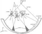
如图1-图5所示,本实施例提供一种大尺度内凹弧面多视觉线结构光三维测量实验装置,包括相机扇形基座1、激光器基座2、连接底板3、测量往复机构4和激光器调节往复机构5,测量往复机构4通过连接底板3与激光器调节往复机构5连接,用于驱动激光器调节往复机构5整体往复移动,激光器调节往复机构5与激光器基座2连接,用于驱动激光器基座2往复移动,激光器基座2上安装有激光器6,相机扇形基座1包括扇形底盘101和调节基块102,扇形底盘101通过压紧轴103转动连接在连接底板3上,通过锁紧压紧轴103能够使相机扇形基座1与连接底板3保持相对固定,扇形底盘101上设有圆弧调节滑槽104和多个调节基块102,各调节基块102能够沿圆弧调节滑槽104在扇形底盘101上移动,各调节基块102上均连接有一个调节基块锁定件,通过调节基块锁定件能够将调节基块102锁定于扇形底盘101上,各调节基块102上均安装有相机7。As shown in Figures 1 to 5, this embodiment provides a large-scale concave arc surface multi-visual line structured light three-dimensional measurement experimental device, including a fan-shaped
本装置设置可调节相机7视角的相机扇形基座1,可以通过增减相机7和调节相机7视角保证测量视场,另外设置可锁紧的压紧轴103,将扇形底盘101绕压紧轴103转动可调节相机7视场与激光面夹角,另一方面设置激光器调节往复机构5,可以调节激光器6相对各相机7的间距,相较于现有相机与激光器位置固定的测量装置,本装置有效适应了不同尺度和弧度内凹物体表面三维测量的需求,提升了测量装置的普适性。本装置中测量相机7的数量可以依据测量尺度大小而增减,从而保证单个像素的表征尺度尽可能小,不会因为测量尺度变大而增加单个像素表征尺度,从而保证测量精度。The device is provided with a camera fan-shaped
本实施例中,调节基块102设置有三个,两端的调节基块102上的相机7分别为第一从相机701和第二从相机702,中间的调节基块102上的相机7为主相机703。可根据实际测量情况,设置不同数量的相机7,对应设置与相机7数量相同的调节基块102。In this embodiment, there are three adjustment base blocks 102, the cameras 7 on the adjustment base blocks 102 at both ends are the
本实施例中,测量往复机构4和激光器调节往复机构5均为直线丝杆滑块机构;直线丝杆滑块机构包括步进电机801、丝杆802、滑块803、导轨804和固定基座805,步进电机801固定连接在固定基座805上,丝杆802转动连接在固定基座805上并由步进电机801驱动旋转,导轨804固定连接在固定基座805上,滑块803螺纹连接在丝杆802上并与导轨804滑动连接。采用直线丝杆滑块机构进行往复驱动,移动平稳,便于进行控制。In this embodiment, both the measuring
本实施例中,连接底板3通过螺栓固定连接在测量往复机构4的滑块803上,连接底板3一端通过螺栓与激光器调节往复机构5的固定基座805连接,另一端设有带压紧轴连接孔301的第一凸台302,扇形底盘101上设有带穿孔105的第二凸台106,压紧轴103穿过压紧轴连接孔301和穿孔105后与锁紧螺母螺纹连接。其中,连接底板3中部设有用于与测量往复机构4的滑块803螺栓连接的测量往复机构连接孔303,连接底板3远离第一凸台302的一端设有用于与激光器调节往复机构5的固定基座805螺栓连接的激光器调节往复机构连接孔304。当扇形底盘101的角度调节好后,拧紧锁紧螺母即可使扇形底盘101与连接底板3保持相对固定。In this embodiment, the connecting
本实施例中,激光器基座2包括支撑底座201、两个紧固夹块202和两个紧固螺栓203,支撑底座201通过螺栓固定连接在激光器调节往复机构5的滑块803上,支撑底座201上表面固定设有两个支撑柱204,各支撑柱204顶端均设有安装孔,两个紧固夹块202分别位于支撑柱204的两侧,两个紧固夹块202相对的两面上设有相配合的弧形凹槽205,各紧固夹块202的两端分别设有与两个安装孔相对应的两个通孔,通过紧固螺栓203穿过通孔和安装孔与紧固螺母206连接,将激光器6夹紧固定于两个紧固夹块202之间的弧形凹槽205中。结构简单,激光器6的安装固定方便快捷。In this embodiment, the
本实施例中,调节基块锁定件为梅花胶头螺丝,梅花胶头螺丝穿过圆弧调节滑槽104螺纹连接在调节基块102上,调节基块102移动到位后,拧紧梅花胶头螺丝即可将调节基块102锁定于扇形底盘101上,结构简单,操作方便。In this embodiment, the locking part of the adjusting base block is a plum blossom screw, and the plum blossom screw is threaded through the
本实施例中,测量往复机构4中的丝杆802与激光器调节往复机构5中的丝杆802互相平行,各相机7的镜头均沿圆弧调节滑槽104的径向方向朝外设置。In this embodiment, the
一种大尺度内凹弧面多视觉线结构光三维测量方法,如图6所示,该方法包括:A three-dimensional measurement method for structured light with multiple visual lines on a large-scale concave arc surface, as shown in Figure 6, the method includes:
步骤S1:构建设定相机的线-面测量模型和相邻相机图像拼接变换矩阵;其中,所述构建相邻相机图像拼接变换矩阵,具体包括:Step S1: Construct the line-surface measurement model of the set camera and the adjacent camera image stitching transformation matrix; wherein, the construction of the adjacent camera image stitching transformation matrix specifically includes:
步骤S11:利用棋盘格标定方法,获取各相机的内外参数。Step S11: Use the checkerboard calibration method to obtain the internal and external parameters of each camera.
步骤S12:根据所述各相机的内外参数,构建相邻相机图像拼接变换矩阵。具体地,相邻相机图像拼接变换矩阵为:Step S12: According to the extrinsic and extrinsic parameters of each camera, construct an image stitching transformation matrix of adjacent cameras. Specifically, the adjacent camera image stitching transformation matrix is:

此外,应用简易棋盘格,构建设定相机的线-面测量模型。In addition, a simple checkerboard is used to construct a line-surface measurement model of a set camera.
步骤S2:获取各相机同步拍摄的内凹弧面的光条图像。Step S2: Obtain the light strip images of the concave arc surface captured synchronously by each camera.
步骤S3:根据所述相邻相机图像拼接变换矩阵,将所述各相机同步拍摄的内凹弧面的光条图像进行拼接,得到设定相机坐标系下的完整图像。Step S3: According to the stitching transformation matrix of the adjacent camera images, the light strip images of the concave arc surface captured synchronously by the cameras are stitched together to obtain a complete image in the set camera coordinate system.
步骤S4:提取所述完整图像的光条中心。Step S4: extracting the light bar center of the complete image.
步骤S5:利用所述设定相机的线-面测量模型,将所述光条中心的二维像素坐标进行转换,得到三维坐标。Step S5: Using the line-surface measurement model of the set camera, convert the two-dimensional pixel coordinates of the center of the light bar to obtain three-dimensional coordinates.
在本实施例中,如图7所示,该方法采用的基本原理是三角测量,充分利用了相邻相机之间存在公共视场区域的特点,对相机之间成像光条数据进行有机融合方法。具体地,大尺度内凹弧面多视觉线结构光三维测量原理为:In this embodiment, as shown in Figure 7, the basic principle adopted by this method is triangulation, which makes full use of the characteristics of the common field of view between adjacent cameras, and performs an organic fusion method for the imaging light strip data between the cameras . Specifically, the three-dimensional measurement principle of structured light with multiple visual lines on a large-scale concave arc surface is as follows:
等角度圆周阵列的多个相机分别拍摄内凹弧面局部小范围的连续光条图像,由于相邻相机之间存在公共视场区域,因此任一时刻相邻相机采集图像中具有相同目标体的成像区域。利用该区域图像,并结合图像拼接技术,将所有图像转换到设定相机(称为“主相机”)的成像坐标系,得到该设定相机坐标系下的一张完整光条图像。再经完整光条图像的光条中心的提取和主相机的“线-面模型”变换,将光条中心二维像素坐标转换成真实三维坐标,以实现三维测量。Multiple cameras in an equiangular circular array respectively capture local small-scale continuous light strip images on the concave arc surface. Since there is a common field of view area between adjacent cameras, the images collected by adjacent cameras have the same target at any time. imaging area. Using the image of this area, combined with image stitching technology, all images are converted to the imaging coordinate system of the set camera (called "main camera"), and a complete light strip image under the set camera coordinate system is obtained. After the extraction of the light bar center of the complete light bar image and the transformation of the "line-surface model" of the main camera, the two-dimensional pixel coordinates of the light bar center are converted into real three-dimensional coordinates to realize three-dimensional measurement.
由于各相机相对位置固定,成像坐标系转换关系不变,得到相邻相机图像具有固定的图像拼接关系:Since the relative positions of each camera are fixed and the transformation relationship of the imaging coordinate system remains unchanged, the adjacent camera images have a fixed image stitching relationship:
x1=K1M1X,x2=K2M2X;其中,K1、K2和M1、M2分别为相机的内参和外参,x1、x2分别为相邻相机公共区域空间某点X的成像坐标。x1 =K1 M1 X, x2 =K2 M2 X; among them, K1 , K2 and M1 , M2 are the internal and external parameters of the camera respectively, and x1 and x2 are the adjacent cameras The imaging coordinates of a point X in the public area space.
根据成像原理,构建出成像坐标x1、x2之间的关系:

利用本发明提供的大尺度内凹弧面多视觉线结构光三维测量实验装置及方法对大尺度内凹弧面进行三维测量的具体实施过程如下:The specific implementation process of three-dimensional measurement of large-scale concave arc surface by using the three-dimensional measurement experimental device and method of multi-visual line structured light on large-scale concave arc surface provided by the present invention is as follows:
第一步:装置调整。根据待测内凹弧面物体尺度、形状等,调节主从相机在圆弧调节滑槽104上的位置以调整各相机视角,调节激光器基座2来调整好激光器6光面,再利用激光器调节往复机构5调整相机7与激光器6相对位置,以获得最佳的测量效果。The first step: device adjustment. According to the size and shape of the concave arc surface object to be measured, adjust the position of the master-slave camera on the
第二步:参数标定。完成主相机703和激光器6的“线-面”测量模型标定;完成所有从相机内外参数标定,并据此构建出相邻相机图像拼接变换矩阵。The second step: parameter calibration. Complete the calibration of the "line-surface" measurement model of the
第三步:扫描测量。实验装置的测量往复机构4牵引搭载有相机7和激光器6的测量机构开始对待测物体表面进行扫描,所有相机同步拍摄物体表面光条图像。The third step: scanning measurement. The
第四步:后期处理。基于先前标定的图像拼接变换矩阵,将任一时刻所有相机同步采集的局部光条图像进行拼接。提取拼接图像的完整光条中心,并基于标定出的主相机703的“线-面”测量模型,将光条中心像素坐标转换成物体表面三维坐标,完成测量。Step 4: Post-processing. Based on the previously calibrated image stitching transformation matrix, the local light strip images collected synchronously by all cameras at any time are stitched. Extract the complete light bar center of the spliced image, and based on the calibrated "line-surface" measurement model of the
本发明提供的大尺度内凹弧面多视觉线结构光三维测量实验装置及方法的优点如下所述:The advantages of the large-scale concave arc surface multi-visual line structured light three-dimensional measurement experimental device and method provided by the present invention are as follows:
(1)降低标定难度。本发明装置及方法需要标定的参数包括:所有从相机的内外参数(构建相邻相机图像拼接变换矩阵)、主相机的“线-面模型”,标定工具为简易棋盘格。而现有类似测量装置(相机、激光器数量相同的情况)配以“全局统一法”,需要标定参数包括:所有相机的“线-面模型”、所有相机局部坐标到全局坐标的变换关系,标定工具为具有某些特殊几何特征的高精度定制标定靶标。相较而言本发明标定参数较少、标定工具简单,因此标定难度大大降低。(1) Reduce the difficulty of calibration. The parameters that need to be calibrated by the device and method of the present invention include: all internal and external parameters of the secondary cameras (constructing the image stitching transformation matrix of adjacent cameras), the "line-surface model" of the main camera, and the calibration tool is a simple checkerboard. However, the existing similar measurement devices (with the same number of cameras and lasers) are equipped with the "global unified method", and the calibration parameters need to include: the "line-surface model" of all cameras, the transformation relationship between local coordinates and global coordinates of all cameras, calibration The tool is a high-precision custom calibration target with some special geometric features. In comparison, the present invention has fewer calibration parameters and simple calibration tools, so the calibration difficulty is greatly reduced.
(2)提升测量装置普适性。本发明装置为适应不同尺度和弧度的内凹物体测量需求。一方面设计了可调节相机视角的相机扇形基座,相机扇形基座上有圆弧调节滑槽、调节基块,可以通过增减相机和调节相机视角保证测量视场,另外在相机扇形基座底部设计了可压紧的压紧轴,绕压紧轴转动可调节相机视场与激光面夹角。另一方面设计了激光器调节往复机构,可以调节激光器相对主从相机的间距。相较于现有相机与激光器位置固定的测量装置,上述设计有效适应了不同尺度和弧度内凹物体表面三维测量的需求。(2) Improve the universality of the measuring device. The device of the invention is adapted to the measurement requirements of concave objects of different scales and radians. On the one hand, a camera fan-shaped base with adjustable camera angle is designed. There are arc adjustment chute and adjustment base on the camera fan-shaped base, which can ensure the measurement field of view by increasing or decreasing the camera and adjusting the camera angle of view. In addition, the camera fan-shaped base A compressible compression shaft is designed at the bottom, and the angle between the camera field of view and the laser surface can be adjusted by rotating around the compression shaft. On the other hand, a laser adjustment reciprocating mechanism is designed, which can adjust the distance between the laser and the master-slave camera. Compared with the existing measuring devices with fixed positions of cameras and lasers, the above-mentioned design effectively adapts to the requirements of three-dimensional measurement of surfaces of concave objects of different scales and radians.
(3)提高测量精度。首先,测量相机数量可以依据测量尺度大小而增减,从而保证单个像素的表征尺度尽可能小,不会因为测量尺度变大而增加单个像素表征尺度,从而保证测量精度。另外,光条图像拼接采用了标定好的图像拼接变换矩阵,相较于基于特征点搜索的图像“映射拼接”,其拼接精度更高,有效提升了最终的三维测量精度。(3) Improve measurement accuracy. First of all, the number of measurement cameras can be increased or decreased according to the measurement scale, so as to ensure that the representation scale of a single pixel is as small as possible, and the representation scale of a single pixel will not be increased due to the increase of the measurement scale, so as to ensure the measurement accuracy. In addition, the light strip image stitching uses a calibrated image stitching transformation matrix. Compared with the image "mapping stitching" based on feature point search, its stitching accuracy is higher, which effectively improves the final three-dimensional measurement accuracy.
本发明中应用了具体个例对本发明的原理及实施方式进行了阐述,以上实施例的说明只是用于帮助理解本发明的方法及其核心思想;同时,对于本领域的一般技术人员,依据本发明的思想,在具体实施方式及应用范围上均会有改变之处。综上所述,本说明书内容不应理解为对本发明的限制。In the present invention, specific examples have been used to illustrate the principle and implementation of the present invention. The description of the above embodiments is only used to help understand the method and core idea of the present invention; meanwhile, for those of ordinary skill in the art, according to the present invention The idea of the invention will have changes in the specific implementation and scope of application. In summary, the contents of this specification should not be construed as limiting the present invention.
Claims (10)

Priority Applications (1)
| Application Number | Priority Date | Filing Date | Title |
|---|---|---|---|
| CN202211075541.1ACN115420217A (en) | 2022-09-05 | 2022-09-05 | Experimental device and method for three-dimensional measurement of large-scale concave arc surface with multiple visual lines structured light |
Applications Claiming Priority (1)
| Application Number | Priority Date | Filing Date | Title |
|---|---|---|---|
| CN202211075541.1ACN115420217A (en) | 2022-09-05 | 2022-09-05 | Experimental device and method for three-dimensional measurement of large-scale concave arc surface with multiple visual lines structured light |
Publications (1)
| Publication Number | Publication Date |
|---|---|
| CN115420217Atrue CN115420217A (en) | 2022-12-02 |
Family
ID=84202930
Family Applications (1)
| Application Number | Title | Priority Date | Filing Date |
|---|---|---|---|
| CN202211075541.1APendingCN115420217A (en) | 2022-09-05 | 2022-09-05 | Experimental device and method for three-dimensional measurement of large-scale concave arc surface with multiple visual lines structured light |
Country Status (1)
| Country | Link |
|---|---|
| CN (1) | CN115420217A (en) |
Cited By (1)
| Publication number | Priority date | Publication date | Assignee | Title |
|---|---|---|---|---|
| CN117268354A (en)* | 2023-11-22 | 2023-12-22 | 苏州图立方科技有限公司 | Laser marking device for pasting AGV navigation two-dimensional code |
Citations (7)
| Publication number | Priority date | Publication date | Assignee | Title |
|---|---|---|---|---|
| CN203091973U (en)* | 2013-03-27 | 2013-07-31 | 余姚市富达电子有限公司 | Laser welding joint adjusting device |
| CN105606150A (en)* | 2015-12-22 | 2016-05-25 | 中国矿业大学(北京) | Road comprehensive detection method and system based on line structured light and geological radar |
| CN208203729U (en)* | 2018-03-30 | 2018-12-07 | 广州供电局有限公司 | guide rod fastener |
| CN109802535A (en)* | 2019-03-05 | 2019-05-24 | 浙江晋一特种电机有限公司 | A kind of body anti-deformation device and its installation method for permanent magnet synchronous motor |
| CN111384656A (en)* | 2020-03-09 | 2020-07-07 | 湖南城市学院 | High-energy ultrashort pulse fiber laser |
| CN213342149U (en)* | 2020-08-19 | 2021-06-01 | 洛阳爱普特光能科技有限公司 | A photovoltaic power station component cooling device |
| CN216415577U (en)* | 2021-12-22 | 2022-05-03 | 刁赫宣 | Pet footbath device |
- 2022
- 2022-09-05CNCN202211075541.1Apatent/CN115420217A/enactivePending
Patent Citations (7)
| Publication number | Priority date | Publication date | Assignee | Title |
|---|---|---|---|---|
| CN203091973U (en)* | 2013-03-27 | 2013-07-31 | 余姚市富达电子有限公司 | Laser welding joint adjusting device |
| CN105606150A (en)* | 2015-12-22 | 2016-05-25 | 中国矿业大学(北京) | Road comprehensive detection method and system based on line structured light and geological radar |
| CN208203729U (en)* | 2018-03-30 | 2018-12-07 | 广州供电局有限公司 | guide rod fastener |
| CN109802535A (en)* | 2019-03-05 | 2019-05-24 | 浙江晋一特种电机有限公司 | A kind of body anti-deformation device and its installation method for permanent magnet synchronous motor |
| CN111384656A (en)* | 2020-03-09 | 2020-07-07 | 湖南城市学院 | High-energy ultrashort pulse fiber laser |
| CN213342149U (en)* | 2020-08-19 | 2021-06-01 | 洛阳爱普特光能科技有限公司 | A photovoltaic power station component cooling device |
| CN216415577U (en)* | 2021-12-22 | 2022-05-03 | 刁赫宣 | Pet footbath device |
Non-Patent Citations (1)
| Title |
|---|
| 李涛涛: "多视觉线结构光高精度三维信息提取技术研究", 中国博士学位论文全文数据库 信息科技辑, no. 12, 15 December 2018 (2018-12-15), pages 138 - 61* |
Cited By (2)
| Publication number | Priority date | Publication date | Assignee | Title |
|---|---|---|---|---|
| CN117268354A (en)* | 2023-11-22 | 2023-12-22 | 苏州图立方科技有限公司 | Laser marking device for pasting AGV navigation two-dimensional code |
| CN117268354B (en)* | 2023-11-22 | 2024-04-02 | 苏州图立方科技有限公司 | Laser marking device for pasting AGV navigation two-dimensional code |
Similar Documents
| Publication | Publication Date | Title |
|---|---|---|
| CN104897060B (en) | Large field of view global measurement method using coordinate tracking control board | |
| CN108980539B (en) | Multifreedom motion shooting platform device and spatial point coordinate measuring method | |
| CN103776390B (en) | Multi-view-field data splicing method based on three-dimensional natural texture data scanning machine | |
| CN102692214B (en) | Narrow space binocular vision measuring and positioning device and method | |
| CN210293630U (en) | Calibration plate rack device for lens test | |
| CN102364299A (en) | A Calibration Technology for Multiple Structured Light Projection 3D Surface Measuring Heads | |
| CN201340256Y (en) | Test bed used for binocular stereo vision measuring | |
| CN102620684A (en) | Three-dimensional topography mark comparison measuring instrument | |
| CN105716542A (en) | Method for three-dimensional data registration based on flexible feature points | |
| CN108596929A (en) | The light of fusion plane grid depth calculation cuts data modeling reconstructing method | |
| CN110793464A (en) | Large-field fringe projection vision three-dimensional measurement system and method | |
| CN115420217A (en) | Experimental device and method for three-dimensional measurement of large-scale concave arc surface with multiple visual lines structured light | |
| CN214228369U (en) | A device for collecting object image information for three-dimensional reconstruction | |
| CN103728315A (en) | Large-aperture element surface detection device and corresponding damage quick localization method | |
| CN111951380B (en) | Three-dimensional reconstruction device and method based on monocular stereoscopic vision | |
| CN112489110A (en) | Optical hybrid three-dimensional imaging method for underwater dynamic scene | |
| CN117073579A (en) | Structured light binocular three-dimensional measurement system and method based on stripe projection | |
| CN202304767U (en) | Three-dimensional outline measurement device based on multiple sensors | |
| CN107845145A (en) | Three-dimensional reconfiguration system and method under a kind of electron microscopic scene | |
| CN107135336A (en) | a camera array | |
| CN104864855A (en) | Single-camera omnidirectional stereoscopic vision sensor and design method thereof | |
| CN109000566A (en) | Scanning three-dimensional imaging laser and CCD two-dimensional imaging combination measurement method and device | |
| CN111425705A (en) | Lifting guide rail type large-breadth mural hyperspectral data acquisition device | |
| CN205718957U (en) | A kind of object dimensional data acquisition unit based on image | |
| CN111242901A (en) | Space point-based global calibration system and method for automobile detection camera without common view field |
Legal Events
| Date | Code | Title | Description |
|---|---|---|---|
| PB01 | Publication | ||
| PB01 | Publication | ||
| SE01 | Entry into force of request for substantive examination | ||
| SE01 | Entry into force of request for substantive examination |