CN115415997A - Antagonistic pneumatic muscle lower limb power exoskeleton - Google Patents
Antagonistic pneumatic muscle lower limb power exoskeletonDownload PDFInfo
- Publication number
- CN115415997A CN115415997ACN202210978564.7ACN202210978564ACN115415997ACN 115415997 ACN115415997 ACN 115415997ACN 202210978564 ACN202210978564 ACN 202210978564ACN 115415997 ACN115415997 ACN 115415997A
- Authority
- CN
- China
- Prior art keywords
- muscle
- hip
- joint
- connecting plate
- antagonistic
- Prior art date
- Legal status (The legal status is an assumption and is not a legal conclusion. Google has not performed a legal analysis and makes no representation as to the accuracy of the status listed.)
- Granted
Links
Images


Classifications
- B—PERFORMING OPERATIONS; TRANSPORTING
- B25—HAND TOOLS; PORTABLE POWER-DRIVEN TOOLS; MANIPULATORS
- B25J—MANIPULATORS; CHAMBERS PROVIDED WITH MANIPULATION DEVICES
- B25J9/00—Programme-controlled manipulators
- B25J9/0006—Exoskeletons, i.e. resembling a human figure
Landscapes
- Engineering & Computer Science (AREA)
- Robotics (AREA)
- Mechanical Engineering (AREA)
- Rehabilitation Tools (AREA)
Abstract
Translated fromChinese
Description
Translated fromChinese技术领域technical field
本发明涉及助力机器人技术领域,尤其是涉及一种拮抗式气动肌肉下肢动力外骨骼。The invention relates to the technical field of power-assisted robots, in particular to an antagonistic pneumatic muscle lower limb powered exoskeleton.
背景技术Background technique
肌肉外骨骼是一种可穿戴式机器人,采用人体仿生结构,可以辅助人体承担较重的载荷,能够为人体提供保护、支撑与增强的功能。The muscular exoskeleton is a wearable robot that adopts the bionic structure of the human body, which can assist the human body to bear heavy loads, and can provide protection, support and enhancement functions for the human body.
外骨骼可以通过对应人体关节,由人穿戴在身上进行工作,根据关节驱动力的方式,主要有电动伺服驱动外骨骼、液压伺服外骨骼、气动伺服外骨骼以及混合动力伺服外骨骼。在以上驱动方式中,电动伺服的优点是易于安装与控制,但其功率/质量比较低,所以驱动关节的电机性能指标较高,价格也更昂贵;液压伺服驱动具有大的功率/质量比,但是由于易泄露且系统辅助元件较多,成本也较高。Exoskeletons can be worn on the body by corresponding to the joints of the human body. According to the driving force of the joints, there are mainly electric servo-driven exoskeletons, hydraulic servo exoskeletons, pneumatic servo exoskeletons, and hybrid servo exoskeletons. Among the above driving methods, the advantage of electric servo is that it is easy to install and control, but its power/mass ratio is low, so the performance index of the motor driving the joint is higher, and the price is more expensive; hydraulic servo drive has a large power/mass ratio, However, due to easy leakage and many auxiliary components of the system, the cost is also high.
发明内容Contents of the invention
本发明要解决的技术问题是提供一种增加实用性,简化结构、降低造价,适合于大规模应用于工农业生产、医疗等环境的拮抗式气动肌肉下肢动力外骨骼。The technical problem to be solved by the present invention is to provide an antagonistic pneumatic muscle lower extremity powered exoskeleton that increases practicability, simplifies structure, reduces cost, and is suitable for large-scale application in industrial and agricultural production, medical treatment and other environments.
为解决上述技术问题,本发明包括一种拮抗式气动肌肉下肢动力外骨骼,包括两个呈左右对称设置的背髋连接板,所述背髋连接板上均依次设有髋关节总成、膝关节总成和足底总成;所述髋关节总成包括包括髋背活动连接板,髋背活动连接板上安装有用于驱动髋关节动作的髋关人工肌肉组件;所述膝关节总成通过腿杆铰接板安装在髋背活动连接板上,所述膝关节总成包括竖直设置的大腿杆,所述大腿杆上安装有用于驱动膝关节动作的大腿人工肌肉组件;所述足底总成通过小腿连接板安装在大腿杆上,所述足底总成包括竖直设置的小腿杆,所述小腿杆上安装有用于驱动踝关节动作的足底人工肌肉组件;两个所述背髋连接板通过背板组件相连接。In order to solve the above technical problems, the present invention includes an antagonistic pneumatic muscle lower extremity powered exoskeleton, which includes two dorsal hip connecting plates arranged symmetrically on the left and right. joint assembly and plantar assembly; the hip joint assembly includes a hip dorsal articulation plate, on which a hip joint artificial muscle assembly for driving the action of the hip joint is mounted; the knee joint assembly passes through The leg bar hinge plate is installed on the hip dorsal movable connection plate, and the knee joint assembly includes a vertically arranged thigh bar, and the thigh artificial muscle assembly for driving the action of the knee joint is installed on the thigh bar; the plantar assembly installed on the thigh bar through the shank connecting plate, the plantar assembly includes a vertically arranged shank bar, and the plantar artificial muscle assembly for driving the ankle joint is installed on the shank bar; the two dorsal hip The connection boards are connected through the backplane assembly.
所述髋关人工肌肉组件包括铰接在髋背活动连接板上的髋关节一号肌肉铰接件和髋关节二号肌肉铰接件;所述髋关节一号肌肉铰接件和髋关节二号肌肉铰接件上分别铰接有髋关节一号气动肌肉和髋关节二号气动肌肉;所述髋背活动连接板上与腿杆铰接板对应位置处设有髋关节拮抗同步轮,所述髋关节拮抗同步轮与髋背活动连接板之间转动连接,且所述髋关节拮抗同步轮上安装有与之配套的髋关节拮抗同步带,所述髋关节拮抗同步带的两端分别与髋关节一号气动肌肉和髋关节二号气动肌肉的下端固接。The artificial muscle assembly of the hip joint includes the No. 1 muscle hinge of the hip joint and the No. 2 muscle hinge of the hip joint hinged on the hip back movable link plate; the No. 1 muscle hinge of the hip joint and the No. 2 muscle hinge of the hip joint The No. 1 aerodynamic muscle of the hip joint and the No. 2 aerodynamic muscle of the hip joint are hinged respectively; the position corresponding to the hinged plate of the leg rod on the movable connecting plate of the hip back is provided with a hip joint antagonism synchronous wheel, and the antagonism synchronous wheel of the hip joint is connected with the The hip-back movable connection plates are rotationally connected, and the hip-joint antagonism synchronous belt is installed on the hip-joint antagonism synchronous wheel, and the two ends of the hip-joint antagonism synchronous belt are respectively connected to the No. 1 pneumatic muscle of the hip joint and The lower end of the No. 2 pneumatic muscle of the hip joint is fixed.
进一步的:所述腿杆铰接板包括呈左右对称设在髋背活动连接板两侧的髋关节一号腿杆铰接板和髋关节二号腿杆铰接板,所述髋关节拮抗同步轮的两端分别与髋关节一号腿杆铰接板和髋关节二号腿杆铰接板固接,所述髋关节一号腿杆铰接板上固接有髋关节编码器固定架,所述髋关节编码器固接在髋关节编码器固定架随着髋关节一号腿杆铰接板同步转动。Further: the hinged plate of the leg bar includes the hinged plate of the No. 1 leg bar of the hip joint and the hinged plate of the No. 2 leg bar of the hip joint which are symmetrically arranged on both sides of the hip back movable connecting plate, and the two sides of the antagonized synchronous wheel of the hip joint The ends are respectively affixed to the hinged plate of the No. 1 leg of the hip joint and the hinged plate of the No. 2 leg of the hip joint. The encoder fixed frame fixed on the hip joint rotates synchronously with the hinge plate of the No. 1 leg rod of the hip joint.
进一步的:所述大腿人工肌肉组件包括铰接在大腿杆前后两侧的大腿一号肌肉铰接件和大腿二号肌肉铰接件,所述大腿一号肌肉铰接件和大腿二号肌肉铰接件上分别铰接有大腿一号气动人工肌肉和大腿二号气动人工肌肉,所述大腿杆下端的左右两侧呈对称分别固接有用于支撑膝关节旋转的膝关节一号连接板和膝关节二号连接板,所述膝关节一号连接板和膝关节二号连接板之间转动安装有膝关节拮抗同步轮,所述膝关节拮抗同步轮上设有与之相配套的膝关节拮抗同步带,所述膝关节拮抗同步带的两端分别与大腿一号气动人工肌肉和大腿二号气动人工肌肉固接,大腿杆的内侧安装有大腿固定绑带,并可以根据使用者的具体体型进行上下位置的调整。Further: the artificial muscle assembly of the thigh includes the No. 1 thigh muscle hinge and the No. 2 muscle hinge of the thigh hinged on the front and rear sides of the thigh bar, and the No. 1 thigh muscle hinge and the No. 2 muscle hinge of the thigh are hinged respectively There are the No. 1 pneumatic artificial muscle of the thigh and the No. 2 pneumatic artificial muscle of the thigh. The left and right sides of the lower end of the thigh rod are symmetrically connected with the No. 1 knee joint connecting plate and the No. 2 knee joint connecting plate for supporting the rotation of the knee joint. A knee joint antagonism synchronous wheel is rotatably installed between the No. 1 knee joint connecting plate and the No. 2 knee joint antagonism synchronous wheel, and a matching knee antagonism synchronous belt is provided on the knee joint antagonism synchronous wheel. The two ends of the joint antagonism synchronous belt are fixedly connected with the No. 1 pneumatic artificial muscle of the thigh and the No. 2 pneumatic artificial muscle of the thigh. The inner side of the thigh rod is equipped with a thigh fixing strap, and the upper and lower positions can be adjusted according to the specific body shape of the user.
进一步的:所述小腿连接板包括分别固定安装在膝关节拮抗同步轮两端的小腿一号连接板和小腿二号连接板,所述小腿一号连接板和小腿二号连接板均与膝关节一号连接板和膝关节二号连接板互不干涉。Further: the shank connecting plate includes the No. 1 connecting plate of the shank and the No. 2 connecting plate of the shank respectively fixedly installed at the two ends of the antagonizing synchronous wheel of the knee joint, and the No. 1 connecting plate of the shank and the No. 2 connecting plate of the shank are all connected to the first joint The No. 2 connecting plate and the No. 2 connecting plate of the knee joint do not interfere with each other.
进一步的:所述膝关节二号连接板上固接有膝关节编码器支架,所述膝关节编码器支架上固接有膝关节编码器。Further: a knee joint encoder support is fixedly connected to the No. 2 connecting plate of the knee joint, and a knee joint encoder is fixedly connected to the knee joint encoder support.
进一步的:所述足底人工肌肉组件包括分别铰接在小腿杆前后两侧的足底一号肌肉铰接件和足底二号肌肉铰接件,所述足底一号肌肉铰接件和足底二号肌肉铰接件上分别铰接有一号气动人工肌肉和足底二号气动人工肌肉,所述小腿杆的下端通过足腿连接板铰接有足部铰接块,所述一号气动人工肌肉和足底二号气动人工肌肉的另一端分别与足部铰接块铰接进行力矩传递;所述足腿连接板包括固定安装在小腿杆左右两侧的足腿一号连接板和足腿二号连接板,所述足腿一号连接板和足腿二号连接板分别与足部铰接块的两侧铰接实现一个自由度的有限转动,所述足部铰接块上焊接有底板。Further: the plantar artificial muscle assembly includes the plantar No. 1 muscle hinge and the plantar No. 2 muscle hinge respectively hinged on the front and rear sides of the calf bar, and the plantar No. 1 muscle hinge and the plantar No. 2 muscle hinge A No. 1 pneumatic artificial muscle and a No. 2 plantar pneumatic artificial muscle are respectively hinged on the muscle hinge. The other end of the pneumatic artificial muscle is respectively hinged with the foot hinge block for torque transmission; the foot leg connection plate includes the first leg connection plate and the second leg connection plate fixedly installed on the left and right sides of the calf bar. The No. 1 connecting plate of the leg and the No. 2 connecting plate of the foot leg are respectively hinged to the two sides of the foot hinge block to realize a limited rotation with a degree of freedom, and the base plate is welded on the foot hinge block.
进一步的:所述小腿杆的内侧安装有小腿固定绑带,并可以根据使用者的体型进行自由调整;所述足底板上设有足底板一号绑带与足底板二号绑带。Further: the inner side of the calf bar is equipped with a calf fixing strap, and can be freely adjusted according to the user's body shape; the No. 1 strap of the sole and the No. 2 strap of the sole are provided on the sole.
综上所述,本发明拮抗式气动肌肉下肢动力外骨骼通过图中所示的绑带与穿戴者进行交互连接,并可以根据穿戴者的体型、肢体尺寸,通过调整背髋连接板与背板组件的安装尺寸,来适配穿戴者的腰部,通过调整各个腿杆上的固定绑带安装位置,来适配穿戴者的下肢,通过调整足底板一号绑带与足底板二号绑带,来适配穿戴者的脚部。通过以上预操作,便可以实现穿戴者与外骨骼的适配。In summary, the antagonistic pneumatic muscle lower extremity powered exoskeleton of the present invention is interactively connected to the wearer through the straps shown in the figure, and can be adjusted according to the wearer's body shape and limb size by adjusting the back hip connecting plate and the back plate The installation size of the components is adapted to the wearer's waist. By adjusting the installation position of the fixed straps on each leg bar, it is adapted to the wearer's lower limbs. By adjusting the No. 1 strap of the sole plate and the No. 2 strap of the sole plate, to fit the wearer's foot. Through the above pre-operations, the fit between the wearer and the exoskeleton can be realized.
当穿戴者开始行走时,控制器判断人体的动作意图,通过控制箱内的控制组件对髋关节总成中的髋关节一号气动肌肉和髋关节二号气动肌肉根据控制指令进行相应的充放气,气动肌肉收缩时产生力矩,驱动髋关节拮抗同步轮进行转动,从而为髋关节提供必要的辅助力矩,减轻人体肌肉负担;对膝关节总成中的大腿一号气动人工肌肉和大腿二号气动人工肌肉根据控制指令进行相应的充放气,气动肌肉收缩时产生力矩,驱动膝关节拮抗同步轮进行转动,从而为膝关节提供必要的辅助力矩,减轻人体肌肉负担;对足底总成中的足底一号气动人工肌肉和足底二号气动人工肌肉根据控制指令进行相应的充放气,气动肌肉收缩时产生力矩,驱动足部铰接块进行转动,从而为踝关节提供必要的辅助力矩,减轻人体肌肉负担;各个关节产生力矩所需要的人工肌肉气压以及转动角度都通过控制器内部的运动学与动力学控制算法实现。When the wearer starts to walk, the controller judges the movement intention of the human body, and through the control components in the control box, the No. 1 pneumatic muscle of the hip joint and the No. 2 pneumatic muscle of the hip joint are charged and discharged according to the control instructions. Air, when the pneumatic muscle contracts, it generates torque, which drives the hip joint to rotate against the synchronous wheel, thereby providing the necessary auxiliary torque for the hip joint and reducing the burden on human muscles; for the thigh No. 1 pneumatic artificial muscle and the thigh No. 2 artificial muscle in the knee joint assembly The pneumatic artificial muscle is inflated and deflated according to the control command. When the pneumatic muscle contracts, torque is generated to drive the knee joint to rotate against the synchronous wheel, thereby providing the necessary auxiliary torque for the knee joint and reducing the burden on human muscles; The No. 1 pneumatic artificial muscle of the sole and the No. 2 pneumatic artificial muscle of the sole perform corresponding inflation and deflation according to the control instructions. When the pneumatic muscles contract, torque is generated to drive the foot hinge block to rotate, thereby providing the necessary auxiliary torque for the ankle joint. , to reduce the burden on human muscles; the artificial muscle air pressure and rotation angle required by each joint to generate torque are realized through the kinematics and dynamics control algorithm inside the controller.
附图说明Description of drawings
下面结合附图和具体实施方式对本发明作进一步详细说明:Below in conjunction with accompanying drawing and specific embodiment the present invention is described in further detail:
图1为拮抗式气动肌肉下肢动力外骨骼整体结构示意图;Figure 1 is a schematic diagram of the overall structure of an antagonistic pneumatic muscle lower limb powered exoskeleton;
图2为髋关节总成结构示意图;Fig. 2 is a schematic diagram of the structure of the hip joint assembly;
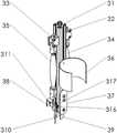
图3为膝关节总成结构示意图;Fig. 3 is a structural schematic diagram of the knee joint assembly;
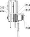
图4为膝关节总成局部结构示意图;Fig. 4 is a schematic diagram of the local structure of the knee joint assembly;
图5为足底总成结构示意图;Fig. 5 is a schematic diagram of the plantar assembly structure;
图6为足底总成等轴测结构示意图;Fig. 6 is a schematic diagram of the isometric structure of the plantar assembly;
图中:1、背髋连接板;2、髋关节总成;21、髋背活动连接板;22、髋关节一号肌肉铰接件;23、髋关节二号肌肉铰接件;24、髋关节一号气动肌肉;25、髋关节二号气动肌肉;26、髋关节拮抗同步带;27、髋关节拮抗同步轮;28、髋关节编码器;29、髋关节编码器固定架;210、髋关节一号腿杆铰接板;211、髋关节二号腿杆铰接板;3、膝关节总成;31、大腿杆;32、大腿一号肌肉铰接件;33、大腿二号肌肉铰接件;34、大腿一号气动人工肌肉;35、大腿二号气动人工肌肉;36、大腿固定绑带;37、膝关节一号连接板;38、膝关节二号连接板;39、小腿一号连接板;310、小腿二号连接板;311、膝关节编码器;312、膝关节一号轴承组件;313、膝关节二号轴承组件;314、一号带轮垫板;315、二号带轮垫板;316、膝关节拮抗同步轮;317、膝关节拮抗同步带;318、膝关节编码器支架;4、足底总成;41、小腿杆;42、足底一号肌肉铰接板;43、足底二号肌肉铰接件;44、足底一号气动人工肌肉;45、足底二号气动人工肌肉;46、足部铰接块;47、足腿一号连接板;48、足腿二号连接板;49、小腿固定绑带;410、足底板;411、足底板一号绑带;412、足底板二号绑带;5、背板组件;51、控制箱。In the figure: 1. Back hip joint plate; 2. Hip joint assembly; 21. Hip dorsal movable joint plate; 22. No. 1 hip muscle joint; 23. Hip joint No. 2 muscle joint; 24. Hip joint No. 1 No. 2 pneumatic muscle; 25. No. 2 hip joint pneumatic muscle; 26. Hip joint antagonistic synchronous belt; 27. Hip joint antagonistic synchronous wheel; 28. Hip joint encoder; 29. Hip joint encoder fixing frame; No. 1 leg rod hinge plate; 211. No. 2 leg rod hinge plate of hip joint; 3. Knee joint assembly; 31. Thigh rod; 32. No. 1 thigh muscle joint; 33. No. 2 thigh muscle joint; 34. Thigh No. 1 pneumatic artificial muscle; 35. No. 2 thigh pneumatic artificial muscle; 36. Thigh fixing strap; 37. No. 1 knee joint connecting plate; 38. No. 2 knee joint connecting plate; 39. No. 1 calf connecting plate; 310. No. 2 connecting plate of lower leg; 311, knee joint encoder; 312, No. 1 bearing assembly of knee joint; 313, No. 2 bearing assembly of knee joint; 314, No. 1 pulley backing plate; 315, No. 2 pulley backing plate; 316 , Knee joint antagonistic synchronous wheel; 317, Knee joint antagonistic synchronous belt; 318, Knee joint encoder support; 4, Plantar assembly; 41, Calf bar; No. muscle joint; 44. No. 1 pneumatic artificial muscle of the sole; 45. No. 2 pneumatic artificial muscle of the sole; 46. Foot hinge block; 47. No. 1 connecting plate of the foot; 48. No. 2 connecting plate of the foot; 49, calf fixing strap; 410, sole plate; 411, the No. 1 strap of the sole plate; 412, the No. 2 strap of the sole plate; 5, the back panel assembly; 51, the control box.
具体实施方式detailed description
下面结合附图和具体的实施例对本发明作进一步的详细说明,但本发明并不限于这些实施例。The present invention will be further described in detail below in conjunction with the accompanying drawings and specific embodiments, but the present invention is not limited to these embodiments.
如图1所示为一种拮抗式气动肌肉下肢动力外骨骼,包括依次相连接的背板组件5、左部和右部,左部和右部结构完全相同,均包括背髋连接板1、髋关节总成2、膝关节总成3、足底总成4。As shown in Figure 1, it is an antagonistic pneumatic muscle lower extremity powered exoskeleton, which includes a
如图2所示,髋关节总成2包括与背髋连接板1相配合的髋背活动连接板21,髋关节一号肌肉铰接件22,髋关节二号肌肉铰接件23,髋关节一号气动肌肉24,髋关节二号气动肌肉25,髋关节拮抗同步带26,髋关节拮抗同步轮27,髋关节编码器28,髋关节编码器固定架29,髋关节一号腿杆铰接板210,髋关节二号腿杆铰接板211。As shown in Figure 2, the hip
所述髋背活动连接板21通过直槽孔与背髋连接板1上的直槽孔相互配合,通过螺栓可以实现伸缩可调的固定,从而可以实现整个髋关节总成2的前后距离。The hip-dorsal movable connecting
所述髋关节一号肌肉铰接件22和髋关节二号肌肉铰接件23分别通过铰接在髋背活动连接板21上,圆周方向存在一个自由度;髋关节一号气动肌肉24和髋关节二号气动肌肉25的一端分别铰接在髋关节一号肌肉铰接件22和髋关节二号肌肉铰接件23上,并在圆周方向存在一个自由度,上述髋关节肌肉铰接件与髋关节气动肌肉大的圆周转动方向为正交关系。The No. 1
所述髋关节一号气动肌肉24和髋关节二号气动肌肉25的另一端分别与髋关节拮抗同步带26的两端固定连接;髋关节拮抗同步带26与髋关节拮抗同步轮27圆周配合,可以实现传动;髋关节一号腿杆铰接板210和髋关节二号腿杆铰接板211分别与髋关节拮抗同步轮27的两个端面固定连接,实现同步转动;髋关节编码器固定架29与髋关节一号腿杆铰接板210固定连接,髋关节编码器28的外壳固定安装在髋关节编码器固定架29上,并可随着髋关节一号腿杆铰接板210同步转动;髋关节编码器28的内环与髋背活动连接板21的固定轴相连接,使两者固定。The other ends of the No. 1
如图3和图4所示,膝关节总成3包括大腿杆31以及安装在大腿杆31上的膝关节总成3,所述膝关节总成3中,大腿一号肌肉铰接件32和大腿二号肌肉铰接件33铰接在大腿杆31的两侧,用来铰接大腿一号气动人工肌肉34和大腿二号气动人工肌肉35的一端,膝关节一号连接板37和膝关节二号连接板38对称安装在大腿杆31的下端,组成一对支撑件用来支撑膝关节的旋转组件;膝关节拮抗同步轮316通过一根轴同心安装在膝关节一号连接板37和膝关节二号连接板38之间;一号带轮垫板314、二号带轮垫板315分别安装在膝关节拮抗同步轮316的两端,用来调整膝关节拮抗同步轮316的安装间隙;膝关节拮抗同步带317与膝关节拮抗同步轮316齿形配合安装,用来传递扭矩,同时膝关节拮抗同步带317的两端分别与大腿一号气动人工肌肉34和大腿二号气动人工肌肉35的另一端固定连接;小腿一号连接板39和小腿二号连接板310对称安装在膝关节拮抗同步轮316的两个端面;膝关节编码器支架318固定安装在膝关节二号连接板38上;膝关节编码器311通过其外壳固定安装在膝关节编码器支架318上;膝关节一号轴承组件312与膝关节二号轴承组件313分别固定安装在膝关节一号连接板37和膝关节二号连接板38上,用来支撑安装膝关节拮抗同步轮316;大腿固定绑带36通过螺栓固定安装在大腿杆31的内侧,并可以根据使用者的具体体型进行上下位置的调整。As shown in Figures 3 and 4, the knee joint assembly 3 includes a thigh bar 31 and the knee joint assembly 3 installed on the thigh bar 31, in the knee joint assembly 3, the No. 1 thigh muscle hinge 32 and the thigh No. 2 muscle articulator 33 is hinged on the both sides of thigh bar 31, is used for hinged one end of No. 1 pneumatic artificial muscle 34 of thigh and No. 2 pneumatic artificial muscle 35 of thigh, the No. 1 connecting plate 37 of knee joint and the No. 2 connecting plate of knee joint 38 is symmetrically installed on the lower end of the thigh bar 31, forming a pair of supports to support the rotating assembly of the knee joint; the knee joint antagonism synchronous wheel 316 is installed concentrically on the No. 1 connecting plate 37 of the knee joint and connected to the No. 2 knee joint through a shaft Between the plates 38; the No. 1 pulley backing plate 314 and the No. 2 pulley backing plate 315 are installed on the two ends of the knee joint antagonism synchronous wheel 316 respectively, and are used to adjust the installation gap of the knee joint antagonism synchronous wheel 316; the knee joint antagonism synchronous The belt 317 is installed in conjunction with the teeth of the knee joint antagonizing synchronous wheel 316 to transmit torque, while the two ends of the knee joint antagonizing synchronous belt 317 are respectively fixed to the other end of the No. 1 pneumatic artificial muscle 34 of the thigh and the No. 2 pneumatic artificial muscle 35 of the thigh Connection; the No. 1 connecting plate 39 of the lower leg and the No. 2 connecting plate 310 of the lower leg are symmetrically installed on the two end surfaces of the antagonizing synchronous wheel 316 of the knee joint; the knee joint encoder bracket 318 is fixedly installed on the No. 2 connecting plate 38 of the knee joint; the knee joint code The device 311 is fixedly installed on the knee joint encoder bracket 318 through its shell; the No. 1 knee joint bearing assembly 312 and the No. 2 knee joint bearing assembly 313 are respectively fixedly installed on the No. 1 knee joint connecting plate 37 and the No. 2 knee joint connecting plate 38 On the top, it is used to support and install the knee joint antagonistic synchronous wheel 316; the thigh fixing strap 36 is fixedly installed on the inner side of the thigh bar 31 by bolts, and can adjust the upper and lower positions according to the user's specific body type.
如图5和图6所示,足底总成4包括小腿杆41以及安装在小腿杆41上的足底总成4;足底一号肌肉铰接件42和足底二号肌肉铰接件43分别固定安装在小腿杆41的前后两侧,用来铰接安装足底一号气动人工肌肉44和足底二号气动人工肌肉45;足部铰接块46两端的分别与足底一号气动人工肌肉44和足底二号气动人工肌肉45的另一端铰接安装,可以进行力矩传递;足腿一号连接板47和足腿二号连接板48分别固接在小腿杆41的两侧,并与足部铰接块46的中间位置处铰接,实现一个自由度的有限转动;小腿固定绑带49通过螺栓固定安装在小腿杆41的内侧,并可以根据使用者的体型进行自由调整;足部铰接块46的内侧焊接有足底板410,足底板一号绑带411与足底板二号绑带412固定安装在足底板410上。As shown in Figures 5 and 6, the
背板组件上安装有控制箱51。A
该拮抗式气动肌肉下肢动力外骨骼通过图中所示的绑带与穿戴者进行交互连接,并可以根据穿戴者的体型、肢体尺寸,通过调整背髋连接板1与背板组件5的安装尺寸,来适配穿戴者的腰部,通过调整各个腿杆上的固定绑带安装位置,来适配穿戴者的下肢,通过调整足底板一号绑带411与足底板二号绑带412,来适配穿戴者的脚部。通过以上预操作,便可以实现穿戴者与外骨骼的适配。The antagonistic pneumatic muscle lower limb powered exoskeleton is interactively connected to the wearer through the straps shown in the figure, and can adjust the installation size of the back
当穿戴者开始行走时,控制器判断人体的动作意图,通过控制箱51内的控制组件对髋关节总成2中的髋关节一号气动肌肉24和髋关节二号气动肌肉25根据控制指令进行相应的充放气,气动肌肉收缩时产生力矩,驱动髋关节拮抗同步轮27进行转动,从而为髋关节提供必要的辅助力矩,减轻人体肌肉负担;对膝关节总成3中的大腿一号气动人工肌肉34和大腿二号气动人工肌肉35根据控制指令进行相应的充放气,气动肌肉收缩时产生力矩,驱动膝关节拮抗同步轮316进行转动,从而为膝关节提供必要的辅助力矩,减轻人体肌肉负担;对足底总成4中的足底一号气动人工肌肉44和足底二号气动人工肌肉45根据控制指令进行相应的充放气,气动肌肉收缩时产生力矩,驱动足部铰接块46进行转动,从而为踝关节提供必要的辅助力矩,减轻人体肌肉负担;各个关节产生力矩所需要的人工肌肉气压以及转动角度都通过控制器内部的运动学与动力学控制算法实现。When the wearer starts to walk, the controller judges the action intention of the human body, and the No. 1
本发明的描述中,术语“上”、“下”、“左”、“右”、“内”、“外”等指示的方向或位置关系的术语是基于附图所示的方向或位置关系,这仅仅是为了便于描述,而不是指示或暗示所述装置或元件必须具有特定的方位、以特定的方位构造和操作,因此不能理解为对本发明的限制。In the description of the present invention, terms such as "upper", "lower", "left", "right", "inner", "outer" and other indicated directions or positional relationships are based on the directions or positional relationships shown in the accompanying drawings , which is only for convenience of description, but does not indicate or imply that the device or element must have a specific orientation, be constructed and operated in a specific orientation, and thus should not be construed as limiting the present invention.
综上所述,本发明不限于上述具体实施方式。本领域技术人员,在不脱离本发明的精神和范围的前提下,可做若干的更改和修饰,所有这些变化均应落入本发明的保护范围。To sum up, the present invention is not limited to the above specific embodiments. Those skilled in the art can make several changes and modifications without departing from the spirit and scope of the present invention, and all these changes should fall within the protection scope of the present invention.
Claims (8)
Priority Applications (1)
| Application Number | Priority Date | Filing Date | Title |
|---|---|---|---|
| CN202210978564.7ACN115415997B (en) | 2022-08-16 | 2022-08-16 | Antagonistic pneumatic muscle lower limb power exoskeleton |
Applications Claiming Priority (1)
| Application Number | Priority Date | Filing Date | Title |
|---|---|---|---|
| CN202210978564.7ACN115415997B (en) | 2022-08-16 | 2022-08-16 | Antagonistic pneumatic muscle lower limb power exoskeleton |
Publications (2)
| Publication Number | Publication Date |
|---|---|
| CN115415997Atrue CN115415997A (en) | 2022-12-02 |
| CN115415997B CN115415997B (en) | 2025-07-29 |
Family
ID=84198847
Family Applications (1)
| Application Number | Title | Priority Date | Filing Date |
|---|---|---|---|
| CN202210978564.7AActiveCN115415997B (en) | 2022-08-16 | 2022-08-16 | Antagonistic pneumatic muscle lower limb power exoskeleton |
Country Status (1)
| Country | Link |
|---|---|
| CN (1) | CN115415997B (en) |
Cited By (1)
| Publication number | Priority date | Publication date | Assignee | Title |
|---|---|---|---|---|
| CN118717483A (en)* | 2024-06-14 | 2024-10-01 | 中国科学院深圳先进技术研究院 | Lower limb powered exoskeleton device for rehabilitation assistance |
Citations (18)
| Publication number | Priority date | Publication date | Assignee | Title |
|---|---|---|---|---|
| US20040133307A1 (en)* | 2002-12-23 | 2004-07-08 | Samsung Electronics Co., Ltd. | Two-legged walking robot |
| KR20050075953A (en)* | 2004-01-19 | 2005-07-26 | 산재의료관리원 | Power-driven walking supporting device |
| US20110066088A1 (en)* | 2007-12-26 | 2011-03-17 | Richard Little | Self contained powered exoskeleton walker for a disabled user |
| CN103991489A (en)* | 2014-05-12 | 2014-08-20 | 上海大学 | Three-freedom-degree leg mechanism driven by pneumatic artificial muscle |
| US20150122559A1 (en)* | 2012-05-31 | 2015-05-07 | Thk Co., Ltd. | Lower limb structure for legged robot, and legged robot |
| CN104721016A (en)* | 2015-03-25 | 2015-06-24 | 北京航空航天大学 | 3UPS parallelly connected metamorphic mechanism for lower limb rehabilitation robot |
| CN204450526U (en)* | 2014-12-31 | 2015-07-08 | 浙江大学 | The ectoskeleton servomechanism that a kind of pneumatic muscles drives |
| CN204698953U (en)* | 2015-05-29 | 2015-10-14 | 陕西科技大学 | A kind of type hydraulic actuator lower limb exoskeleton bionic device |
| CN204723350U (en)* | 2015-05-26 | 2015-10-28 | 陕西科技大学 | A kind of lower limb power assisting device based on pneumatic muscles |
| CN205073244U (en)* | 2015-10-12 | 2016-03-09 | 哈尔滨工程大学 | Parallel low limbs ectoskeleton rehabilitation training device |
| CN105644650A (en)* | 2015-12-30 | 2016-06-08 | 哈尔滨工业大学 | Pneumatic-electric combined driving flexible biped robot |
| CN105899177A (en)* | 2013-11-29 | 2016-08-24 | 雷克斯生物有限公司 | Walker |
| JP2016221680A (en)* | 2016-09-23 | 2016-12-28 | 株式会社国際電気通信基礎技術研究所 | Drive mechanism |
| CN106335049A (en)* | 2016-11-09 | 2017-01-18 | 中国矿业大学 | Lower limb exosbone assisting device driven by pneumatic muscle |
| CN108656100A (en)* | 2018-05-22 | 2018-10-16 | 嘉兴学院 | Human emulated robot based on cylinder |
| CN109124983A (en)* | 2018-07-03 | 2019-01-04 | 浙江大学 | A kind of lower limb rehabilitation exoskeleton system based on pneumatic muscles |
| CN109589246A (en)* | 2017-09-30 | 2019-04-09 | 江苏鹤林智能机械有限公司 | A kind of high intensity is surged muscle driving ectoskeleton |
| CN114346994A (en)* | 2021-12-30 | 2022-04-15 | 嘉兴学院 | Robot based on multi-group antagonistic pneumatic muscles |
- 2022
- 2022-08-16CNCN202210978564.7Apatent/CN115415997B/enactiveActive
Patent Citations (18)
| Publication number | Priority date | Publication date | Assignee | Title |
|---|---|---|---|---|
| US20040133307A1 (en)* | 2002-12-23 | 2004-07-08 | Samsung Electronics Co., Ltd. | Two-legged walking robot |
| KR20050075953A (en)* | 2004-01-19 | 2005-07-26 | 산재의료관리원 | Power-driven walking supporting device |
| US20110066088A1 (en)* | 2007-12-26 | 2011-03-17 | Richard Little | Self contained powered exoskeleton walker for a disabled user |
| US20150122559A1 (en)* | 2012-05-31 | 2015-05-07 | Thk Co., Ltd. | Lower limb structure for legged robot, and legged robot |
| CN105899177A (en)* | 2013-11-29 | 2016-08-24 | 雷克斯生物有限公司 | Walker |
| CN103991489A (en)* | 2014-05-12 | 2014-08-20 | 上海大学 | Three-freedom-degree leg mechanism driven by pneumatic artificial muscle |
| CN204450526U (en)* | 2014-12-31 | 2015-07-08 | 浙江大学 | The ectoskeleton servomechanism that a kind of pneumatic muscles drives |
| CN104721016A (en)* | 2015-03-25 | 2015-06-24 | 北京航空航天大学 | 3UPS parallelly connected metamorphic mechanism for lower limb rehabilitation robot |
| CN204723350U (en)* | 2015-05-26 | 2015-10-28 | 陕西科技大学 | A kind of lower limb power assisting device based on pneumatic muscles |
| CN204698953U (en)* | 2015-05-29 | 2015-10-14 | 陕西科技大学 | A kind of type hydraulic actuator lower limb exoskeleton bionic device |
| CN205073244U (en)* | 2015-10-12 | 2016-03-09 | 哈尔滨工程大学 | Parallel low limbs ectoskeleton rehabilitation training device |
| CN105644650A (en)* | 2015-12-30 | 2016-06-08 | 哈尔滨工业大学 | Pneumatic-electric combined driving flexible biped robot |
| JP2016221680A (en)* | 2016-09-23 | 2016-12-28 | 株式会社国際電気通信基礎技術研究所 | Drive mechanism |
| CN106335049A (en)* | 2016-11-09 | 2017-01-18 | 中国矿业大学 | Lower limb exosbone assisting device driven by pneumatic muscle |
| CN109589246A (en)* | 2017-09-30 | 2019-04-09 | 江苏鹤林智能机械有限公司 | A kind of high intensity is surged muscle driving ectoskeleton |
| CN108656100A (en)* | 2018-05-22 | 2018-10-16 | 嘉兴学院 | Human emulated robot based on cylinder |
| CN109124983A (en)* | 2018-07-03 | 2019-01-04 | 浙江大学 | A kind of lower limb rehabilitation exoskeleton system based on pneumatic muscles |
| CN114346994A (en)* | 2021-12-30 | 2022-04-15 | 嘉兴学院 | Robot based on multi-group antagonistic pneumatic muscles |
Non-Patent Citations (1)
| Title |
|---|
| 项忠霞;赵明;高飞;金腾;胡志刚;张健;: "一种外骨骼式康复机器人训练效果仿真", 天津大学学报(自然科学与工程技术版), no. 07, 3 November 2015 (2015-11-03), pages 695 - 701* |
Cited By (1)
| Publication number | Priority date | Publication date | Assignee | Title |
|---|---|---|---|---|
| CN118717483A (en)* | 2024-06-14 | 2024-10-01 | 中国科学院深圳先进技术研究院 | Lower limb powered exoskeleton device for rehabilitation assistance |
Also Published As
| Publication number | Publication date |
|---|---|
| CN115415997B (en) | 2025-07-29 |
Similar Documents
| Publication | Publication Date | Title |
|---|---|---|
| CN109223456B (en) | Lower limb exoskeleton robot system based on man-machine terminal interaction | |
| US11432988B2 (en) | Actuation system for hip orthosis | |
| CN109009866B (en) | Sitting type lower limb exoskeleton rehabilitation robot | |
| CN107411939B (en) | A special power-assisted rehabilitation robot for people with unilateral lower limb disabilities | |
| CN203060231U (en) | Wearable lower limb exoskeleton walking-assisting robot | |
| CN103054692B (en) | Wearable lower limb exoskeleton walking-assisted robot | |
| JP6647225B2 (en) | Leg straightening device and straightening device | |
| CN110103207B (en) | A flexible lower limb exoskeleton that assists walking | |
| CN204121372U (en) | A kind of wearable lower limb exoskeleton walk help decompression robot device | |
| CN107928996B (en) | A semi-passive lightweight lower limb exoskeleton | |
| CN106726363A (en) | A kind of wearable bionical hydraulic pressure lower limb rehabilitation walk help mechanical device | |
| CN115137618B (en) | A wearable lower limb exoskeleton rehabilitation and assistance robot | |
| CN101810533A (en) | Walking aid exoskeleton rehabilitation robot | |
| CN107174488B (en) | A wheeled drive self-balancing power ectoskeleton of sole for spinal cord injury patient | |
| CN111571572B (en) | Wearable power-assisted flexible exoskeleton | |
| CN113181009B (en) | Novel self-balancing ectoskeleton robot | |
| CN209237264U (en) | Removable ankle-joint exoskeleton rehabilitation image training robot | |
| Allemand et al. | Design of a new lower extremity orthosis for overground gait training with the WalkTrainer | |
| CN115245446B (en) | Knee joint exoskeleton with rigidity adjusting and energy recovering functions and training method thereof | |
| CN110897834A (en) | An adjustable lower limb exoskeleton device suitable for gait training in children with cerebral palsy | |
| CN111658434A (en) | Knee hyperextension flexible exoskeleton rehabilitation robot based on pneumatic muscles and rehabilitation method | |
| KR20220098532A (en) | Wearable Assistance Device | |
| CN108161909A (en) | A kind of bionical lower limb exoskeleton robot carried for auxiliary | |
| JP7716113B2 (en) | Self-aligning mechanisms in passive and powered exoskeletons | |
| CN112022618B (en) | Rigid-flexible coupling wearable walking assisting exoskeleton system |
Legal Events
| Date | Code | Title | Description |
|---|---|---|---|
| PB01 | Publication | ||
| PB01 | Publication | ||
| SE01 | Entry into force of request for substantive examination | ||
| SE01 | Entry into force of request for substantive examination | ||
| GR01 | Patent grant | ||
| GR01 | Patent grant |