CN115414574A - Catheter tip, balloon catheter and blood vessel intervention device - Google Patents
Catheter tip, balloon catheter and blood vessel intervention deviceDownload PDFInfo
- Publication number
- CN115414574A CN115414574ACN202210989111.4ACN202210989111ACN115414574ACN 115414574 ACN115414574 ACN 115414574ACN 202210989111 ACN202210989111 ACN 202210989111ACN 115414574 ACN115414574 ACN 115414574A
- Authority
- CN
- China
- Prior art keywords
- tip
- catheter
- balloon
- tip body
- thick
- Prior art date
- Legal status (The legal status is an assumption and is not a legal conclusion. Google has not performed a legal analysis and makes no representation as to the accuracy of the status listed.)
- Granted
Links
Images


Classifications
- A—HUMAN NECESSITIES
- A61—MEDICAL OR VETERINARY SCIENCE; HYGIENE
- A61M—DEVICES FOR INTRODUCING MEDIA INTO, OR ONTO, THE BODY; DEVICES FOR TRANSDUCING BODY MEDIA OR FOR TAKING MEDIA FROM THE BODY; DEVICES FOR PRODUCING OR ENDING SLEEP OR STUPOR
- A61M25/00—Catheters; Hollow probes
- A61M25/10—Balloon catheters
- A61M25/104—Balloon catheters used for angioplasty
- A—HUMAN NECESSITIES
- A61—MEDICAL OR VETERINARY SCIENCE; HYGIENE
- A61M—DEVICES FOR INTRODUCING MEDIA INTO, OR ONTO, THE BODY; DEVICES FOR TRANSDUCING BODY MEDIA OR FOR TAKING MEDIA FROM THE BODY; DEVICES FOR PRODUCING OR ENDING SLEEP OR STUPOR
- A61M25/00—Catheters; Hollow probes
- A61M25/0021—Catheters; Hollow probes characterised by the form of the tubing
- A61M25/0023—Catheters; Hollow probes characterised by the form of the tubing by the form of the lumen, e.g. cross-section, variable diameter
- A61M25/0026—Multi-lumen catheters with stationary elements
- A—HUMAN NECESSITIES
- A61—MEDICAL OR VETERINARY SCIENCE; HYGIENE
- A61M—DEVICES FOR INTRODUCING MEDIA INTO, OR ONTO, THE BODY; DEVICES FOR TRANSDUCING BODY MEDIA OR FOR TAKING MEDIA FROM THE BODY; DEVICES FOR PRODUCING OR ENDING SLEEP OR STUPOR
- A61M25/00—Catheters; Hollow probes
- A61M25/0043—Catheters; Hollow probes characterised by structural features
- A61M25/0045—Catheters; Hollow probes characterised by structural features multi-layered, e.g. coated
- A—HUMAN NECESSITIES
- A61—MEDICAL OR VETERINARY SCIENCE; HYGIENE
- A61M—DEVICES FOR INTRODUCING MEDIA INTO, OR ONTO, THE BODY; DEVICES FOR TRANSDUCING BODY MEDIA OR FOR TAKING MEDIA FROM THE BODY; DEVICES FOR PRODUCING OR ENDING SLEEP OR STUPOR
- A61M25/00—Catheters; Hollow probes
- A61M25/0067—Catheters; Hollow probes characterised by the distal end, e.g. tips
- A61M25/008—Strength or flexibility characteristics of the catheter tip
- A—HUMAN NECESSITIES
- A61—MEDICAL OR VETERINARY SCIENCE; HYGIENE
- A61M—DEVICES FOR INTRODUCING MEDIA INTO, OR ONTO, THE BODY; DEVICES FOR TRANSDUCING BODY MEDIA OR FOR TAKING MEDIA FROM THE BODY; DEVICES FOR PRODUCING OR ENDING SLEEP OR STUPOR
- A61M25/00—Catheters; Hollow probes
- A61M25/10—Balloon catheters
- A61M2025/1043—Balloon catheters with special features or adapted for special applications
- A61M2025/1088—Balloon catheters with special features or adapted for special applications having special surface characteristics depending on material properties or added substances, e.g. for reducing friction
- A—HUMAN NECESSITIES
- A61—MEDICAL OR VETERINARY SCIENCE; HYGIENE
- A61M—DEVICES FOR INTRODUCING MEDIA INTO, OR ONTO, THE BODY; DEVICES FOR TRANSDUCING BODY MEDIA OR FOR TAKING MEDIA FROM THE BODY; DEVICES FOR PRODUCING OR ENDING SLEEP OR STUPOR
- A61M25/00—Catheters; Hollow probes
- A61M25/10—Balloon catheters
- A61M2025/1043—Balloon catheters with special features or adapted for special applications
- A61M2025/1093—Balloon catheters with special features or adapted for special applications having particular tip characteristics
Landscapes
- Health & Medical Sciences (AREA)
- Life Sciences & Earth Sciences (AREA)
- Heart & Thoracic Surgery (AREA)
- Hematology (AREA)
- Engineering & Computer Science (AREA)
- Anesthesiology (AREA)
- Biomedical Technology (AREA)
- Pulmonology (AREA)
- Biophysics (AREA)
- Animal Behavior & Ethology (AREA)
- General Health & Medical Sciences (AREA)
- Public Health (AREA)
- Veterinary Medicine (AREA)
- Vascular Medicine (AREA)
- Child & Adolescent Psychology (AREA)
- Media Introduction/Drainage Providing Device (AREA)
Abstract
Description
Translated fromChinese技术领域technical field
本申请涉及介入医疗器械领域,尤其涉及一种导管尖端、球囊导管及血管介入装置。The present application relates to the field of interventional medical devices, in particular to a catheter tip, a balloon catheter and a vascular intervention device.
背景技术Background technique
目前市场上现有的PTCA球囊扩张导管中的导管尖端普遍采用内管与导管尖端直接焊接,在两者连接处由球囊延伸段覆盖并将其焊接一起。按照选用的材料类型,目前的尖端包括两类,一类是软尖端,一类是硬尖端。软尖端的好处是柔软度好,对血管的创伤小;尖端能与导丝更好的贴附,能灵活有效的提高导管的灵活性,是目前主要的尖端材料。在使用过程中其缺点也很明显,内管以及尖端的材料都选用了软材质,即使导管内部以及导丝都有润滑涂层,但是软性材料由于存在弹性具有较强的包覆性,容易在导管拐弯受力较大的情况下抱死导丝,导丝不能自由运动,常常导致手术无法正常进行;采用较硬尖端的,最大的缺点是容易对血管组织造成损伤,引发对患者的心血管的再次伤害。At present, the catheter tip in the existing PTCA balloon dilatation catheters on the market is generally directly welded with the inner tube and the catheter tip, and the connection between the two is covered by a balloon extension and welded together. According to the type of material selected, the current tip includes two types, one is a soft tip and the other is a hard tip. The advantage of the soft tip is that it is soft and less traumatic to blood vessels; the tip can be better attached to the guide wire, and can flexibly and effectively improve the flexibility of the catheter. It is currently the main tip material. Its shortcomings are also obvious during use. The materials of the inner tube and the tip are all made of soft materials. Even though the inside of the catheter and the guide wire have lubricating coatings, the soft materials have strong covering properties due to their elasticity and are easy to When the guide wire is locked when the catheter bends and the force is large, the guide wire cannot move freely, which often leads to the failure of the operation; the biggest disadvantage of using a hard tip is that it is easy to cause damage to the vascular tissue and cause damage to the patient's heart. Vascular reinjury.
手术过程中经常会遇到有分叉部位的血管,当血栓或狭窄区域位于血管分叉部位,球囊导管的尖端需要进入分叉血管,由于常规球囊扩张导管的尖端短小,转弯时尖端容易抵触到血管壁,导致转弯不顺利,需要多次尝试进入,延长操作时间。Blood vessels with bifurcations are often encountered during the operation. When the thrombus or stenosis is located at the bifurcation of the blood vessel, the tip of the balloon catheter needs to enter the bifurcation blood vessel. Because the tip of the conventional balloon dilatation catheter is short, the tip is easy to turn when turning. Collision with the vessel wall, resulting in an unsmooth turn, requires multiple attempts to enter, and prolongs the operation time.
此外,常规的PTCA手术需要借助显影剂以及X光,其中显影剂和X光也会对患者造成一定的辐射伤害。In addition, conventional PTCA operations require contrast agents and X-rays, which will also cause certain radiation damage to patients.
申请内容application content
本申请提供一种导管尖端,用以解决现有的导管尖端存在容易将导丝抱死、对血管组织造成损伤以及操作不便的问题。The present application provides a catheter tip, which is used to solve the problems that the existing catheter tip is easy to lock the guide wire, cause damage to the vascular tissue and inconvenient to operate.
为实现上述目的,本申请提供的技术方案是:一种导管尖端,包括:In order to achieve the above object, the technical solution provided by the application is: a catheter tip, comprising:
尖端本体,内部形成有第一腔,所述尖端本体为偏心管体,所述尖端本体形成有厚壁区和与所述厚壁区连接的薄壁区;所述尖端本体的外径由近端向远端逐渐减小,所述尖端本体远端的端部封闭并形成斜面,所述斜面与所述厚壁区的外表面之间的夹角为钝角,所述斜面与所述薄壁区的外表面之间的夹角为锐角,所述厚壁区内设导丝腔,所述导丝腔由所述厚壁区的近端延伸至所述斜面,所述尖端本体的外表面的局部或者全部设置有聚合物层,所述聚合物层的硬度小于所述尖端本体的硬度。The tip body is formed with a first cavity inside, the tip body is an eccentric tube body, and the tip body is formed with a thick-walled area and a thin-walled area connected with the thick-walled area; the outer diameter of the tip body is determined by approximately The end gradually decreases toward the distal end, the end of the distal end of the tip body is closed and forms a bevel, the angle between the bevel and the outer surface of the thick-walled region is an obtuse angle, and the bevel and the thin-wall The included angle between the outer surfaces of the regions is an acute angle, and a guide wire cavity is provided in the thick-walled region, and the guide wire cavity extends from the proximal end of the thick-walled region to the slope, and the outer surface of the tip body A polymer layer is provided on part or all of the tip body, and the hardness of the polymer layer is less than that of the tip body.
优选地,所述尖端本体的管壁内设置弹簧,所述弹簧的弹簧指数由近端至远端递增;或/且所述聚合物层的厚度由近端向远端逐渐变厚。Preferably, a spring is arranged in the tube wall of the tip body, and the spring index of the spring increases from the proximal end to the distal end; or/and the thickness of the polymer layer gradually becomes thicker from the proximal end to the distal end.
优选地,所述尖端本体的外周面套设有套筒,所述套筒的外表面不高于相邻所述聚合物层的外表面。Preferably, the outer peripheral surface of the tip body is covered with a sleeve, and the outer surface of the sleeve is not higher than the outer surface of the adjacent polymer layer.
优选地,所述斜面与所述厚壁区外表面以及所述薄壁区外表面的连接处均通过圆角过渡。Preferably, the joints between the slope and the outer surface of the thick-walled region and the outer surface of the thin-walled region are all transitioned through rounded corners.
优选地,所述导管尖端外周面的平均倾斜角度小于3°。Preferably, the average inclination angle of the outer peripheral surface of the tip of the catheter is less than 3°.
优选地,所述斜面与所述尖端本体的轴线之间的夹角为30°-70°。Preferably, the included angle between the slope and the axis of the tip body is 30°-70°.
优选地,所述尖端本体的近端设置有连接部。Preferably, the proximal end of the tip body is provided with a connecting portion.
本申请还提供一种技术方案:一种球囊导管,包括球囊、外管、内管、针座和如上所述的导管尖端,所述内管穿设于所述外管内,所述外管的远端连接所述球囊的近端,所述内管与所述外管以及所述球囊之间形成充压腔,所述外管和所述内管的近端连接所述针座,所述内管内形成内管腔,所述导管尖端的近端与所述球囊的远端连接,所述内管腔连通所述第一腔。The present application also provides a technical solution: a balloon catheter, including a balloon, an outer tube, an inner tube, a needle hub, and the catheter tip as described above, the inner tube is passed through the outer tube, and the outer tube The distal end of the tube is connected to the proximal end of the balloon, a pressurized cavity is formed between the inner tube, the outer tube and the balloon, and the proximal end of the outer tube and the inner tube is connected to the needle seat, an inner lumen is formed in the inner tube, the proximal end of the catheter tip is connected to the distal end of the balloon, and the inner lumen communicates with the first lumen.
优选地,所述连接部的内表面与所述球囊远端的外表面通过螺纹或胶粘或焊接连接,所述球囊远端的内表面与所述内管的外表面通过胶粘或焊接连接。Preferably, the inner surface of the connection part is connected to the outer surface of the distal end of the balloon by threading or gluing or welding, and the inner surface of the distal end of the balloon is connected to the outer surface of the inner tube by gluing or Solder connection.
本申请还提供一种技术方案:一种血管介入装置,包括压力调节装置和如上所述的球囊导管,所述压力调节装置的输出端通过所述针座与所述内管腔连通,所述压力调节装置用于调节所述第一腔内的压力,以使尖端本体发生偏转。The present application also provides a technical solution: a vascular interventional device, including a pressure regulating device and the above-mentioned balloon catheter, the output end of the pressure regulating device communicates with the inner lumen through the needle seat, and the The pressure regulating device is used to regulate the pressure in the first chamber to deflect the tip body.
本申请提供的导管尖端,通过使用较硬材质的导管尖端可以有效减少对导丝的抱死现象,保证手术顺畅进行,减少医疗事故发生;通过在尖端本体外表面的局部或者全部设置有较软的聚合物层,在手术过程中,导管尖端在接触血管壁时可将对血管壁的损伤减少到最小,不会对患者的心血管造成再次伤害。The catheter tip provided by this application can effectively reduce the locking phenomenon of the guide wire by using the catheter tip made of a harder material, ensure the smooth operation, and reduce the occurrence of medical accidents; During the operation, the tip of the catheter can minimize the damage to the blood vessel wall when it contacts the blood vessel wall, and will not cause re-injury to the patient's cardiovascular system.
附图说明Description of drawings
为了更清楚地说明本申请或现有技术中的技术方案,下面将对实施例或现有技术描述中所需要使用的附图作一简单地介绍,显而易见地,下面描述中的附图是本申请的一些实施例,对于本领域普通技术人员来讲,在不付出创造性劳动的前提下,还可以根据这些附图获得其他的附图。In order to more clearly illustrate the technical solutions in this application or the prior art, the accompanying drawings that need to be used in the description of the embodiments or the prior art will be briefly introduced below. Obviously, the accompanying drawings in the following description are the present For some embodiments of the application, those skilled in the art can also obtain other drawings based on these drawings without creative work.
图1是本申请实施例一提供的导管尖端的侧视剖面结构示意图;Fig. 1 is a side view sectional structural schematic diagram of a catheter tip provided in Embodiment 1 of the present application;
图2是本申请实施例二提供的导管尖端的侧视剖面结构示意图;Fig. 2 is a side view sectional structural schematic diagram of the catheter tip provided in Embodiment 2 of the present application;
图3是图1中沿剖面线A-A所做的剖面结构示意图;Fig. 3 is a schematic sectional structure diagram along section line A-A in Fig. 1;
图4是图1中B处的局部放大结构示意图;Fig. 4 is a schematic diagram of a partially enlarged structure at B in Fig. 1;
图5是本申请实施例提供的包含导管尖端的球囊导管的侧视剖面结构示意图;Fig. 5 is a side view sectional structural schematic diagram of a balloon catheter including a catheter tip provided by an embodiment of the present application;
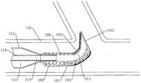
图6是本申请实施例提供的球囊导管处于弯折状态下的侧视剖面结构示意图;Fig. 6 is a side view sectional structural schematic view of the balloon catheter provided in the embodiment of the present application in a bent state;
图7是本申请实施例提供的球囊导管的工作原理示意图;Fig. 7 is a schematic diagram of the working principle of the balloon catheter provided by the embodiment of the present application;
图8是现有技术中球囊导管的工作原理示意图。Fig. 8 is a schematic diagram of the working principle of the balloon catheter in the prior art.
附图标记:Reference signs:
100、尖端本体;101、厚壁区;102、薄壁区;103、斜面;104、导丝腔;105、聚合物层;106、弹簧;107、套筒;108、连接部;109、螺纹;110、内管;111、导丝;112、球囊;113、第一腔;114、内管腔;115、充压腔;116、血管。100, tip body; 101, thick wall area; 102, thin wall area; 103, inclined plane; 104, guide wire cavity; 105, polymer layer; 106, spring; 107, sleeve; 108, connecting part; 109,
具体实施方式detailed description
下面结合附图和实施例对本申请的实施方式作进一步详细描述。以下实施例用于说明本申请,但不能用来限制本申请的范围。The implementation manner of the present application will be further described in detail below with reference to the drawings and embodiments. The following examples are used to illustrate the present application, but cannot be used to limit the scope of the present application.
在本申请实施例的描述中,需要说明的是,术语“中心”、“纵向”、“横向”、“上”、“下”、“前”、“后”、“左”、“右”、“竖直”、“水平”、“顶”、“底”、“内”、“外”等指示的方位或位置关系为基于附图所示的方位或位置关系,仅是为了便于描述本申请实施例和简化描述,而不是指示或暗示所指的装置或元件必须具有特定的方位、以特定的方位构造和操作,因此不能理解为对本申请实施例的限制。此外,术语“第一”、“第二”、“第三”仅用于描述目的,而不能理解为指示或暗示相对重要性。In the description of the embodiments of the present application, it should be noted that the terms "center", "vertical", "transverse", "upper", "lower", "front", "rear", "left", "right" , "vertical", "horizontal", "top", "bottom", "inner", "outer" and other indicated orientations or positional relationships are based on the orientations or positional relationships shown in the drawings, and are only for the convenience of describing this The application embodiments and simplified descriptions do not indicate or imply that the devices or elements referred to must have a specific orientation, be constructed and operated in a specific orientation, and therefore should not be construed as limiting the embodiments of the application. In addition, the terms "first", "second", and "third" are used for descriptive purposes only, and should not be construed as indicating or implying relative importance.
在本申请实施例的描述中,需要说明的是,除非另有明确的规定和限定,术语“相连”、“连接”应做广义理解,例如,可以是固定连接,也可以是可拆卸连接,或一体连接;可以是机械连接,也可以是电连接;可以是直接相连,也可以通过中间媒介间接相连。对于本领域的普通技术人员而言,可以具体情况理解上述术语在本申请实施例中的具体含义。In the description of the embodiments of this application, it should be noted that unless otherwise specified and limited, the terms "connected" and "connected" should be understood in a broad sense, for example, it can be a fixed connection or a detachable connection, Or integrated connection; it can be mechanical connection or electrical connection; it can be direct connection or indirect connection through an intermediary. Those of ordinary skill in the art can understand the specific meanings of the above terms in the embodiments of the present application in specific situations.
在本申请实施例中,除非另有明确的规定和限定,第一特征在第二特征“上”或“下”可以是第一和第二特征直接接触,或第一和第二特征通过中间媒介间接接触。而且,第一特征在第二特征“之上”、“上方”和“上面”可是第一特征在第二特征正上方或斜上方,或仅仅表示第一特征水平高度高于第二特征。第一特征在第二特征“之下”、“下方”和“下面”可以是第一特征在第二特征正下方或斜下方,或仅仅表示第一特征水平高度小于第二特征。In the embodiment of the present application, unless otherwise clearly specified and limited, the first feature may be in direct contact with the first feature or the first feature and the second feature may pass through the middle of the second feature. Media indirect contact. Moreover, "above", "above" and "above" the first feature on the second feature may mean that the first feature is directly above or obliquely above the second feature, or simply means that the first feature is higher in level than the second feature. "Below", "beneath" and "beneath" the first feature may mean that the first feature is directly below or obliquely below the second feature, or simply means that the first feature is less horizontally than the second feature.
在本说明书的描述中,参考术语“一个实施例”、“一些实施例”、“示例”、“具体示例”、或“一些示例”等的描述意指结合该实施例或示例描述的具体特征、结构、材料或者特点包含于本申请实施例的至少一个实施例或示例中。在本说明书中,对上述术语的示意性表述不必须针对的是相同的实施例或示例。而且,描述的具体特征、结构、材料或者特点可以在任一个或多个实施例或示例中以合适的方式结合。此外,在不相互矛盾的情况下,本领域的技术人员可以将本说明书中描述的不同实施例或示例以及不同实施例或示例的特征进行结合和组合。In the description of this specification, descriptions referring to the terms "one embodiment", "some embodiments", "example", "specific examples", or "some examples" mean that specific features described in connection with the embodiment or example , structures, materials or features are included in at least one embodiment or example of the embodiments of the present application. In this specification, the schematic representations of the above terms are not necessarily directed to the same embodiment or example. Furthermore, the described specific features, structures, materials or characteristics may be combined in any suitable manner in any one or more embodiments or examples. In addition, those skilled in the art can combine and combine different embodiments or examples and features of different embodiments or examples described in this specification without conflicting with each other.
下面结合图1-图8描述本申请实施例的导管尖端及球囊导管,图1示例了本申请实施例一提供的导管尖端的侧视剖面结构示意图,如图1所示,导管尖端包括尖端本体100,尖端本体100的内部形成有第一腔,尖端本体100为偏心管体,偏心管体的横截面呈圆形,也可以呈椭圆形,尖端本体100形成有厚壁区101和与厚壁区101连接的薄壁区102。尖端本体100的外径由近端向远端逐渐减小,尖端本体100远端的端部封闭并形成斜面103,斜面103与厚壁区101的外表面之间的夹角为钝角,斜面103与薄壁区102的外表面之间的夹角为锐角,厚壁区101内设导丝腔104,导丝腔104由厚壁区101的近端延伸至斜面103,尖端本体100的外表面的局部或者全部设置有聚合物层105,聚合物层105的硬度小于尖端本体100的硬度。The catheter tip and the balloon catheter of the embodiment of the present application are described below in conjunction with FIGS.
本申请实施例提供的导管尖端,通过使用较硬材质的导管尖端可以有效减少对导丝111的抱死现象,保证手术顺畅进行,减少医疗事故发生;通过在尖端本体100外表面的局部或者全部设置有较软的聚合物层105,在手术过程中,导管尖端在接触血管壁时可将对血管壁的损伤减少到最小,不会对患者的心血管造成再次伤害。The catheter tip provided by the embodiment of the present application can effectively reduce the locking phenomenon of the
这里需要说明的是,本申请的远端和近端是指相对于操作者来定义的。靠近操作者的一端为近端,远离操作者的一端为远端。It should be noted here that the far end and the proximal end in this application are defined relative to the operator. The end close to the operator is the proximal end, and the end far away from the operator is the distal end.
在本申请的实施例中,如图1所示,偏心管体指尖端本体100的轴线与第一腔113的轴线不重合,这就使得尖端本体100形成有厚壁区101和薄壁区102,形成薄壁区102可方便尖端本体100向薄壁区102一侧弯折,方便导管尖端进入普通导管难以进入的血管116中,本申请的实施例中的导管尖端尤其适合进入分叉血管116,降低了手术操作难度。In the embodiment of the present application, as shown in FIG. 1 , the axis of the eccentric
在本申请的实施例中,图4示例了图1中B处的局部放大结构示意图,如图1和图4所示,尖端本体100的管壁内设置弹簧106,弹簧106的外径由近端向远端逐渐减小。弹簧106的弹簧指数由近端至远端递增。这样,当第一腔113内的压力增大时,使得尖端本体100发生偏转。需要说明的是,弹簧指数又称旋绕比,弹簧指数用C=D/d表示,其中,D表示弹簧中径,d表示弹簧钢丝直径。弹簧指数C影响弹簧106的强度、刚度、稳定性及制造的难易。C值大,中径D较大,钢丝直径较小,弹簧106较软,刚性小,容易变形,容易绕制。C值小,则相反,弹簧106较硬,刚性大,不易绕制。弹簧106的横截面的形状可以为圆形、椭圆形、方形或者菱形等。In the embodiment of the present application, Fig. 4 illustrates a schematic diagram of a partially enlarged structure at B in Fig. 1, as shown in Fig. 1 and Fig. tapered distally. The spring index of the
在本申请的实施例中,如图1所示,斜面103与厚壁区101的外表面之间的夹角为图1中的夹角α。斜面103与薄壁区102的外表面之间的夹角为图1中的夹角β。In the embodiment of the present application, as shown in FIG. 1 , the included angle between the
这里需要说明的是,斜面103与厚壁区101的外表面之间的夹角以及斜面103与薄壁区102的外表面之间的夹角均指尖端本体100未发生弯折时的夹角,夹角α与夹角β的大小由斜面103的倾斜角度决定。It should be noted here that the angle between the
在本申请的实施例中,导管尖端的长度为1-8cm,导管尖端的具体长度根据实际需要进行确定,导管尖端的可偏转角度范围为0°-120°。In the embodiment of the present application, the length of the catheter tip is 1-8 cm, the specific length of the catheter tip is determined according to actual needs, and the deflectable angle range of the catheter tip is 0°-120°.
在本申请的实施例中,如图1所示,导丝腔104的近端延伸至厚壁区101的外表面,导丝腔104为一段弧形孔,导丝腔104的横截面为圆形,导丝腔104的直径为导丝直径的1.5倍以上。导丝腔104的内表面设置有亲水涂层或亲油涂层(未示出),这里,将亲水涂层称为第一亲水涂层,第一亲水涂层用于降低导丝111在导丝腔104内滑动时的摩擦阻力(或者滑动阻力),以防止尖端本体100发生弯曲时将导丝111抱死。In the embodiment of the present application, as shown in FIG. 1 , the proximal end of the
第一亲水涂层的厚度为0.004-0.01mm,第一亲水涂层的具体厚度根据实际需要进行确定。第一亲水涂层为聚甲基乙烯基马来酸酐涂层、氨基硅烷类涂层、水凝胶涂层、聚乙烯吡咯烷酮涂层、聚氧化乙烯涂层、聚乙二醇涂层或者丙烯酸型涂层。亲油涂层可以为硅油涂层、聚四氟乙烯涂层。The thickness of the first hydrophilic coating is 0.004-0.01 mm, and the specific thickness of the first hydrophilic coating is determined according to actual needs. The first hydrophilic coating is polymethylvinylmaleic anhydride coating, aminosilane coating, hydrogel coating, polyvinylpyrrolidone coating, polyethylene oxide coating, polyethylene glycol coating or acrylic type coating. The lipophilic coating can be silicone oil coating, polytetrafluoroethylene coating.
在本申请的另一个实施例中,导丝111的远端的表面涂覆有亲水涂层或亲油涂层,以降低导丝111在导丝腔104内滑动时的摩擦阻力,以防止尖端本体100发生弯曲时将导丝111抱死。In another embodiment of the present application, the surface of the distal end of the
在本申请的一个实施例中,如图1所示,聚合物层105的厚度由近端向远端逐渐变厚,聚合物层105的具体厚度根据实际需要进行确定,聚合物层105可以为一层,也可以为两层以上的层叠体。聚合物层105除了减小对血管壁的损伤之外,还可以减小尖端本体100的摩擦阻力,提高尖端本体100的滑动性,提高导管尖端的操控性能。In one embodiment of the present application, as shown in Figure 1, the thickness of the
为了降低尖端本体100的摩擦阻力,聚合物层105的材质可以为聚乙烯、聚丙烯等聚烯烃、聚氯乙烯、聚酯(PET、PBT等)、聚酰胺、聚酰亚胺、聚氨酯、聚苯乙烯、聚碳酸酯、硅树脂、氟类树脂(PTFE、ETFE、PFA等)、或上述几种材料复合而成的材料,优选项为氟类树脂或者含有氟类树脂的复合材料。In order to reduce the frictional resistance of the
在本申请的另一个实施例中,尖端本体100的外表面设置有凸楞或凹槽,聚合物层105设置于具有凸楞或凹槽的区域,设置凸楞或凹槽增加了聚合物层105的附着力,增强了聚合物层105与尖端本体100之间的密合性。当然,增强聚合物层105与尖端本体100之间密合性的方式并不限定于此,也可采用粗糙面加工、化学处理、热处理等方式对尖端本体100的外表面进行处理,或者在聚合物层105与尖端本体100之间设置能够提高密合性的中间层。In another embodiment of the present application, the outer surface of the
在本申请的另一个实施例中,聚合物层105也可以为第二亲水涂层,第二亲水涂层的材质为聚乙烯吡咯烷酮涂层、聚氧化乙烯涂层或者透明酸酯丙烯酸涂层等,优选项为聚乙烯吡咯烷酮涂层。In another embodiment of the present application, the
在本申请的另一个实施例中,聚合物层105背离尖端本体100的一侧设置有第三亲水涂层,第三亲水涂层的材质与第二亲水涂层的材质相同。本实施例中聚合物层105具有润滑的特性,第三亲水涂层可提高尖端本体100的顺滑性,使其容易通过闭塞的血管。In another embodiment of the present application, a third hydrophilic coating is provided on the side of the
在本申请的实施例中,尖端本体100的硬度为55-100邵氏硬度,由于尖端本体100的材质较硬,可以有效减少对导丝111的抱死现象,保证手术顺畅进行,减少医疗事故发生。聚合物层105的硬度为30-50邵氏硬度,由于聚合物层105的硬度较软,聚合物层105设置于尖端本体100的外表面,避免了硬度较硬的尖端本体100与血管116直接进行接触,可将对血管壁的损伤减少到最小,不会对患者的心血管造成再次伤害。In the embodiment of the present application, the hardness of the
在本申请的实施例中,图2示例了本申请实施例二提供的导管尖端的侧视剖面结构示意图,如图2所示,尖端本体100的近端设置有连接部108,连接部108用于连接球囊112、导管或者鞘组件。连接部108呈管状结构,连接部108的内部形成有连接孔,连接孔与尖端本体100内部的第一腔113连通。连接部108的外径为固定值,连接部108与尖端本体100的近端一体成型,当然,也可采用热熔焊接或者粘接等方式进行连接。当尖端本体100的管壁内设置有弹簧106时,弹簧106的近端延伸至连接部108的内部。In the embodiment of the present application, Fig. 2 illustrates a side view cross-sectional structural schematic diagram of the catheter tip provided in the second embodiment of the present application. For connecting
在本申请的一个实施例中,如图2所示,连接部108内部的连接孔与球囊112的远端插接连接,为了加强连接部108与球囊112之间的连接,连接孔近端的外径大于远端的内径,当球囊112的远端插入连接孔时,会越插越紧。In one embodiment of the present application, as shown in FIG. 2 , the connection hole inside the
在本申请的一个实施例中,如图2所示,连接孔的内壁上设置有螺纹109,球囊112的远端与连接孔螺纹109配合。通过采用螺纹109配合的连接方式,可方便可拆卸地将尖端本体100与球囊112连接。In one embodiment of the present application, as shown in FIG. 2 , a
在本申请的实施例三中,图3示例了图1中沿剖面线A-A所做的剖面结构示意图,如图3所示,尖端本体100的外周面套设有套筒107,套筒107呈环形结构,套筒107的横截面为圆形。套筒107的外表面不高于相邻聚合物层105的外表面,套筒107两侧的环形聚合物层对套筒107起到限位作用,提高了套筒107的稳定性。套筒107两侧的环形聚合物层可以为同一聚合物层105,也可为两个独立的聚合物层105。In Embodiment 3 of the present application, FIG. 3 illustrates a schematic cross-sectional structure diagram along the section line A-A in FIG. 1. As shown in FIG. Ring structure, the cross section of the
可以理解的是,尖端本体100的外周面套设有多个套筒107,多个套筒107沿尖端本体100的外周面间隔设置,相邻两个套筒107之间的距离可以相同,也可以不同。It can be understood that the outer peripheral surface of the
在尖端本体100的外周面套设套筒107能够改善导管尖端的回声反射性,这是因为增强尖端本体100和周围环境之间的声阻抗差异。套筒107在B型超声波仪器抓取的灰阶图像中显现为明影,使得操作者能从图像中区分套筒107和周围组织之间的明度差异。金属材质套筒107的优点是容易用胶进行粘接,可以选择厚度为0.01-0.05mm的金属,因为此厚度的金属具有足够的柔性以便包覆在尖端本体100上。套筒107可以采用具有良好柔性的金属,优选项为钛、不锈钢、铂或金。金属套筒107比器官组织和器官液体具有更高的声阻抗值(Z值),有助于构建具有显著Z值差异的界面。Sleeving the
为了改善导管尖端的回声反射性,在套筒107上用激光烧蚀出直径为45μm的半球形凹口。In order to improve the echogenicity of the catheter tip, a hemispherical notch with a diameter of 45 μm was ablated on the
为了改善导管尖端的回声反射性,对套筒107进行喷砂处理,以形成粗糙度为60-120目的粗糙表面。采用超声进行尖端定位,避免使用X光进行尖端定位,减少X光辐射给患者带来额外的医源性损害。To improve the echogenicity of the catheter tip, the
在本申请的实施例中,套筒107的外径小于聚合物层105的外径。由于套筒107为金属材质,且硬度较大,通过使套筒107的外径小于聚合物层105的外径,可避免套筒107与血管116接触,减小了套筒107对血管壁的损伤,不会对患者的心血管造成再次伤害。In an embodiment of the present application, the outer diameter of the
这里需要说明的是,由于聚合物层105的厚度由近端向远端逐渐变厚,为了保证套筒107不会从相邻两段环形聚合物层之间突出,多个套筒107的外径由近端向远端逐渐减小。It should be noted here that since the thickness of the
在本申请的一个实施例中,斜面103与厚壁区101外表面的连接处通过圆角过渡,斜面103与薄壁区102外表面的连接处同样通过圆角过渡。通过采用圆角过渡的方式,可以最大程度上减少手术过程中对血管116造成的损伤。In an embodiment of the present application, the connection between the
在本申请的一个实施例中,导管尖端外周面的平均倾斜角度小于3°。如图1所述,当导管尖端呈圆台体时,导管尖端的外周面任何一区域的倾斜角相等,导管尖端的外周面与导管尖端的轴线之间的夹角与平均倾斜角度相等。当导管尖端外周面上不同区域的倾斜角度不同时,需要先计算每一区域的倾斜角度,再根据计算的倾斜角度计算平均倾斜角度。In one embodiment of the present application, the average inclination angle of the outer peripheral surface of the catheter tip is less than 3°. As shown in Fig. 1, when the catheter tip is in the shape of a frustum of cone, the inclination angle of any area of the outer peripheral surface of the catheter tip is equal, and the angle between the outer peripheral surface of the catheter tip and the axis of the catheter tip is equal to the average inclination angle. When the inclination angles of different areas on the outer peripheral surface of the catheter tip are different, it is necessary to calculate the inclination angle of each area first, and then calculate the average inclination angle according to the calculated inclination angles.
在本申请的一个实施例中,斜面103与尖端本体100的轴线之间的夹角为30°-70°,斜面103与尖端本体100的轴线之间的夹角太小(例如,小于30度),非斜面区域就太长,并会在遇到障碍物时发生弯曲,从而产生了尖端变形、脱落的风险。如果该角度过大(例如,大于75度),由于导管尖端类似于传统的尖端设计,在遇到障碍物时会发生干扰,斜面103的优势将不够显著。In one embodiment of the present application, the angle between the
导管尖端的使用具体流程:The specific process of using the catheter tip:
经皮穿刺成功后,将导丝111推送至血管靶区,将导管尖端沿着导丝111送至分支血管处,尖端本体100的封闭端(远端)位于分支血管进口处,由于导丝111已进入到分支血管内,向前推球囊112,尖端本体100的封闭端沿着导丝111进入分支血管,若夹角较大,向内管110充压,薄壁区102受力较大,尖端本体100向薄壁区102一侧弯折,充压有助于尖端本体100转向。图6示例了本申请实施例提供的球囊导管处于弯折状态下的侧视剖面结构示意图,如图6和图7所示,通过在尖端本体100的远端设置斜面103,可使得尖端本体100不会直接抵触血管116交叉口(图中圆圈位置C),降低血管116损伤的风险,由于有偏心助力,容易通过夹角小的分支血管。After the percutaneous puncture is successful, the
图7示例了本申请实施例提供的球囊导管的工作原理示意图,如图7所示,本申请实施例的导管尖端,通过将导丝腔104设置于厚壁区101,当薄壁区102发生弯折时,导丝111近端离血管116下端近,导丝111的离心角较大,更容易进入分支血管,保证手术顺畅进行,减少医疗事故发生。Figure 7 illustrates a schematic diagram of the working principle of the balloon catheter provided by the embodiment of the present application. When bending occurs, the proximal end of the
图8示例了现有技术中球囊导管的工作原理示意图,如图8所示,在现有技术中,导丝111位于血管116的中心位置,导丝111进入相同角度的分支血管时,由于导丝111的离心角较小,使得尖端直接抵触血管116交叉口(图中圆圈位置D),不容易进入分支血管,因此增加了手术操作难度。Fig. 8 illustrates the schematic diagram of the working principle of the balloon catheter in the prior art. As shown in Fig. 8, in the prior art, the
图5示例了本申请实施例提供的包含导管尖端的球囊导管的侧视剖面结构示意图,如图5所示,本申请还提供一种技术方案:一种球囊导管包括球囊112、外管(未示出)、内管110、针座(未示出)和上述任意一项实施例所述的导管尖端,内管110穿设于外管内,外管的远端连接球囊112的近端,内管110与外管以及球囊112之间形成充压腔115,外管和内管110的近端连接针座,内管110内形成内管腔114,导管尖端的近端与球囊112的远端连接,内管腔114连通第一腔113。通过充压腔115输入或输出充压介质来控制球囊112的收缩和扩张,通过内管腔114输入充压介质以使尖端本体100转向。Fig. 5 illustrates a side view sectional structure diagram of a balloon catheter including a catheter tip provided by an embodiment of the present application. As shown in Fig. 5, the present application also provides a technical solution: a balloon catheter includes a
球囊导管属于现有技术,再次不在赘述,其区别在于上述尖端及其与球囊远端的连接关系。Balloon catheters belong to the prior art and will not be described again. The difference lies in the above-mentioned tip and its connection relationship with the distal end of the balloon.
在本申请的一个实施例中,连接部108的内表面与球囊112远端的外表面通过螺纹或胶粘或焊接连接,球囊112远端的内表面与内管110的外表面通过胶粘或焊接连接。In one embodiment of the present application, the inner surface of the connecting
本申请还提供一种技术方案:一种血管介入装置,包括压力调节装置和上述实施例所述的球囊导管,压力调节装置的输出端通过针座与内管腔114连通,压力调节装置用于调节第一腔113内的压力,以使尖端本体发生偏转。The present application also provides a technical solution: a vascular interventional device, including a pressure regulating device and the balloon catheter described in the above embodiment, the output end of the pressure regulating device communicates with the
在本申请的一个实施例中,压力调节装置包括:In one embodiment of the present application, the pressure regulating device includes:
压力泵,压力泵的输出端连接有连接管,连接管与第二冲压孔连通;a pressure pump, the output end of the pressure pump is connected with a connecting pipe, and the connecting pipe communicates with the second punching hole;
压力表,与压力泵的输出端连通,压力表用于检测压力泵的输出端的压力值。The pressure gauge communicates with the output end of the pressure pump, and the pressure gauge is used to detect the pressure value of the output end of the pressure pump.
本申请还提供一种技术方案:一种应用于如上的血管介入装置的血管介入方法,包括:The present application also provides a technical solution: a vascular intervention method applied to the above vascular intervention device, including:
尖端本体100到达血管连通的分支血管处时,增大尖端本体100管孔内的压力,使尖端本体100偏转,以进入分支血管。When the
最后应说明的是:以上实施例仅用以说明本申请的技术方案,而非对其限制;尽管参照前述实施例对本申请进行了详细的说明,本领域的普通技术人员应当理解:其依然可以对前述各实施例所记载的技术方案进行修改,或者对其中部分技术特征进行等同替换;而这些修改或者替换,并不使相应技术方案的本质脱离本申请各实施例技术方案的精神和范围。Finally, it should be noted that: the above embodiments are only used to illustrate the technical solutions of the present application, rather than limiting them; although the present application has been described in detail with reference to the foregoing embodiments, those of ordinary skill in the art should understand that: it can still Modifications are made to the technical solutions described in the foregoing embodiments, or equivalent replacements are made to some of the technical features; and these modifications or replacements do not make the essence of the corresponding technical solutions deviate from the spirit and scope of the technical solutions of the various embodiments of the present application.
Claims (10)
Priority Applications (1)
| Application Number | Priority Date | Filing Date | Title |
|---|---|---|---|
| CN202210989111.4ACN115414574B (en) | 2022-08-17 | 2022-08-17 | Catheter tip, balloon catheter and blood vessel intervention device |
Applications Claiming Priority (1)
| Application Number | Priority Date | Filing Date | Title |
|---|---|---|---|
| CN202210989111.4ACN115414574B (en) | 2022-08-17 | 2022-08-17 | Catheter tip, balloon catheter and blood vessel intervention device |
Publications (2)
| Publication Number | Publication Date |
|---|---|
| CN115414574Atrue CN115414574A (en) | 2022-12-02 |
| CN115414574B CN115414574B (en) | 2023-04-07 |
Family
ID=84198199
Family Applications (1)
| Application Number | Title | Priority Date | Filing Date |
|---|---|---|---|
| CN202210989111.4AActiveCN115414574B (en) | 2022-08-17 | 2022-08-17 | Catheter tip, balloon catheter and blood vessel intervention device |
Country Status (1)
| Country | Link |
|---|---|
| CN (1) | CN115414574B (en) |
Cited By (1)
| Publication number | Priority date | Publication date | Assignee | Title |
|---|---|---|---|---|
| CN119656450A (en)* | 2024-12-06 | 2025-03-21 | 宁波琳盛高分子材料有限公司 | Catheter tip and forming method thereof |
Citations (9)
| Publication number | Priority date | Publication date | Assignee | Title |
|---|---|---|---|---|
| US20040102719A1 (en)* | 2002-11-22 | 2004-05-27 | Velocimed, L.L.C. | Guide wire control catheters for crossing occlusions and related methods of use |
| US20040116851A1 (en)* | 2002-12-16 | 2004-06-17 | Intraluminal Therapeutics, Inc. | Deflecting catheter |
| US20100217185A1 (en)* | 2007-05-21 | 2010-08-26 | Gad Terliuc | Catheter including a bendable portion |
| US20140046250A1 (en)* | 2011-03-15 | 2014-02-13 | Barts And The London Nhs Trust | Steerable element for use in surgery |
| CN104185491A (en)* | 2011-12-14 | 2014-12-03 | 东莞市迪凯精密管材有限公司 | Placement of soft-coated tip balloon dilatation catheters |
| US20150202089A1 (en)* | 2007-12-20 | 2015-07-23 | Acclarent, Inc. | Eustachian tube dilation balloon with ventilation path |
| WO2015114398A1 (en)* | 2014-02-03 | 2015-08-06 | Medinol Ltd. | Catheter tip assembled with a spring |
| WO2017015163A1 (en)* | 2015-07-17 | 2017-01-26 | TriReme Medical, LLC | Balloon catheter with improved column strength and torque transmission |
| CN215537612U (en)* | 2020-12-22 | 2022-01-18 | 深圳北芯生命科技股份有限公司 | Micro-catheter |
- 2022
- 2022-08-17CNCN202210989111.4Apatent/CN115414574B/enactiveActive
Patent Citations (9)
| Publication number | Priority date | Publication date | Assignee | Title |
|---|---|---|---|---|
| US20040102719A1 (en)* | 2002-11-22 | 2004-05-27 | Velocimed, L.L.C. | Guide wire control catheters for crossing occlusions and related methods of use |
| US20040116851A1 (en)* | 2002-12-16 | 2004-06-17 | Intraluminal Therapeutics, Inc. | Deflecting catheter |
| US20100217185A1 (en)* | 2007-05-21 | 2010-08-26 | Gad Terliuc | Catheter including a bendable portion |
| US20150202089A1 (en)* | 2007-12-20 | 2015-07-23 | Acclarent, Inc. | Eustachian tube dilation balloon with ventilation path |
| US20140046250A1 (en)* | 2011-03-15 | 2014-02-13 | Barts And The London Nhs Trust | Steerable element for use in surgery |
| CN104185491A (en)* | 2011-12-14 | 2014-12-03 | 东莞市迪凯精密管材有限公司 | Placement of soft-coated tip balloon dilatation catheters |
| WO2015114398A1 (en)* | 2014-02-03 | 2015-08-06 | Medinol Ltd. | Catheter tip assembled with a spring |
| WO2017015163A1 (en)* | 2015-07-17 | 2017-01-26 | TriReme Medical, LLC | Balloon catheter with improved column strength and torque transmission |
| CN215537612U (en)* | 2020-12-22 | 2022-01-18 | 深圳北芯生命科技股份有限公司 | Micro-catheter |
Cited By (1)
| Publication number | Priority date | Publication date | Assignee | Title |
|---|---|---|---|---|
| CN119656450A (en)* | 2024-12-06 | 2025-03-21 | 宁波琳盛高分子材料有限公司 | Catheter tip and forming method thereof |
Also Published As
| Publication number | Publication date |
|---|---|
| CN115414574B (en) | 2023-04-07 |
Similar Documents
| Publication | Publication Date | Title |
|---|---|---|
| JP6077646B2 (en) | Medical long body | |
| JP6031087B2 (en) | Balloon catheter | |
| EP2928380B1 (en) | Reinforced catheter transition with flexible tip portion | |
| US9211389B2 (en) | Offset soft tip with proposed tooling | |
| JP2010057831A (en) | Suction catheter | |
| CN115414574A (en) | Catheter tip, balloon catheter and blood vessel intervention device | |
| JP2012501225A (en) | Tip section for monorail catheter | |
| JPWO2017212716A1 (en) | Percutaneous catheter and percutaneous catheter assembly | |
| JPS63181772A (en) | Soft leading end catheter | |
| WO2020175462A1 (en) | Inner tube, catheter, and method for manufacturing inner tube | |
| JP5822140B2 (en) | Thrombus aspiration catheter | |
| JP5253842B2 (en) | Aspiration catheter | |
| US20220401638A1 (en) | Percutaneous catheter | |
| CN215084026U (en) | Catheter tube | |
| CN115487399B (en) | Medical tube and balloon catheter | |
| JP2000217923A (en) | Balloon catheter and method of manufacturing the same | |
| CN118698009A (en) | Extending the guide catheter | |
| JPWO2017175530A1 (en) | Percutaneous catheter | |
| JP2002291900A (en) | Medical device and method of manufacturing the same | |
| JP2011200588A (en) | Balloon catheter and method of manufacturing the same | |
| WO2021182070A1 (en) | Stylet | |
| JP2021053445A (en) | Medical device | |
| JP2005237863A (en) | Catheter and manufacturing method thereof | |
| CN219921849U (en) | Blood inflow cage and catheter pump thereof | |
| US20230347108A1 (en) | Stylet and catheter assembly |
Legal Events
| Date | Code | Title | Description |
|---|---|---|---|
| PB01 | Publication | ||
| PB01 | Publication | ||
| SE01 | Entry into force of request for substantive examination | ||
| SE01 | Entry into force of request for substantive examination | ||
| GR01 | Patent grant | ||
| GR01 | Patent grant |