CN115406738A - An anti-clogging integrated triaxial test device for microbial temperature-controlled grouting reinforcement - Google Patents
An anti-clogging integrated triaxial test device for microbial temperature-controlled grouting reinforcementDownload PDFInfo
- Publication number
- CN115406738A CN115406738ACN202211251954.0ACN202211251954ACN115406738ACN 115406738 ACN115406738 ACN 115406738ACN 202211251954 ACN202211251954 ACN 202211251954ACN 115406738 ACN115406738 ACN 115406738A
- Authority
- CN
- China
- Prior art keywords
- grouting
- sample
- hole
- microbial
- pressure
- Prior art date
- Legal status (The legal status is an assumption and is not a legal conclusion. Google has not performed a legal analysis and makes no representation as to the accuracy of the status listed.)
- Granted
Links
Images


Classifications
- G—PHYSICS
- G01—MEASURING; TESTING
- G01N—INVESTIGATING OR ANALYSING MATERIALS BY DETERMINING THEIR CHEMICAL OR PHYSICAL PROPERTIES
- G01N1/00—Sampling; Preparing specimens for investigation
- G01N1/28—Preparing specimens for investigation including physical details of (bio-)chemical methods covered elsewhere, e.g. G01N33/50, C12Q
- G01N1/286—Preparing specimens for investigation including physical details of (bio-)chemical methods covered elsewhere, e.g. G01N33/50, C12Q involving mechanical work, e.g. chopping, disintegrating, compacting, homogenising
- G—PHYSICS
- G01—MEASURING; TESTING
- G01N—INVESTIGATING OR ANALYSING MATERIALS BY DETERMINING THEIR CHEMICAL OR PHYSICAL PROPERTIES
- G01N3/00—Investigating strength properties of solid materials by application of mechanical stress
- G01N3/02—Details
- G—PHYSICS
- G01—MEASURING; TESTING
- G01N—INVESTIGATING OR ANALYSING MATERIALS BY DETERMINING THEIR CHEMICAL OR PHYSICAL PROPERTIES
- G01N3/00—Investigating strength properties of solid materials by application of mechanical stress
- G01N3/08—Investigating strength properties of solid materials by application of mechanical stress by applying steady tensile or compressive forces
- G01N3/10—Investigating strength properties of solid materials by application of mechanical stress by applying steady tensile or compressive forces generated by pneumatic or hydraulic pressure
- G01N3/12—Pressure testing
- G—PHYSICS
- G01—MEASURING; TESTING
- G01N—INVESTIGATING OR ANALYSING MATERIALS BY DETERMINING THEIR CHEMICAL OR PHYSICAL PROPERTIES
- G01N3/00—Investigating strength properties of solid materials by application of mechanical stress
- G01N3/24—Investigating strength properties of solid materials by application of mechanical stress by applying steady shearing forces
- G—PHYSICS
- G01—MEASURING; TESTING
- G01N—INVESTIGATING OR ANALYSING MATERIALS BY DETERMINING THEIR CHEMICAL OR PHYSICAL PROPERTIES
- G01N2203/00—Investigating strength properties of solid materials by application of mechanical stress
- G01N2203/0014—Type of force applied
- G01N2203/0016—Tensile or compressive
- G01N2203/0019—Compressive
- G—PHYSICS
- G01—MEASURING; TESTING
- G01N—INVESTIGATING OR ANALYSING MATERIALS BY DETERMINING THEIR CHEMICAL OR PHYSICAL PROPERTIES
- G01N2203/00—Investigating strength properties of solid materials by application of mechanical stress
- G01N2203/0014—Type of force applied
- G01N2203/0025—Shearing
Landscapes
- Physics & Mathematics (AREA)
- Health & Medical Sciences (AREA)
- Life Sciences & Earth Sciences (AREA)
- Chemical & Material Sciences (AREA)
- Analytical Chemistry (AREA)
- Biochemistry (AREA)
- General Health & Medical Sciences (AREA)
- General Physics & Mathematics (AREA)
- Immunology (AREA)
- Pathology (AREA)
- Investigating Strength Of Materials By Application Of Mechanical Stress (AREA)
Abstract
Description
Translated fromChinese技术领域technical field
本发明涉及土木工程试验技术领域,特别是涉及一种防堵塞的微生物温控注浆加固一体化三轴试验装置。The invention relates to the technical field of civil engineering tests, in particular to an anti-clogging integrated triaxial test device for microbial temperature-controlled grouting and reinforcement.
背景技术Background technique
微生物注浆加固作为一种新兴的加固方法,其中微生物诱导碳酸钙沉淀(Microbial Induced Calcium carbonate Precipitation,MICP)一直是微生物岩土的研究热点,MICP方法利用特定产脲酶细菌,水解尿素产生
为使微生物加固方法在实际工程中大规模推广与应用,通过室内试验研究微生物注浆加固是不可或缺的。微生物注浆加固效果与细菌活性和脲酶活性等密切相关吗,而温度对细菌的新陈代谢有显著影响,也直接影响脲酶的水解能力。现有的注浆设备与方法通常是在特定设备中对试样进行注浆加固,加固完成后取出试样再进行后续物理力学实验,然而在取样与装样过程中不可避免的对试样产生扰动,并且试样所处的温度环境发生变化从而对试样产生影响。同时,常用注浆模具注浆孔容易被注浆过程中产生的碳酸钙沉淀堵塞。显然,已有仪器设备无法避免加固后试样与试验所用试样状态变化所带来的影响,以及试样模具堵塞对加固试验所带来的影响,从而对微生物注浆加固的室内试验的精准性与大范围推广的应用性增加难度。In order to promote the large-scale promotion and application of microbial reinforcement methods in actual engineering, it is indispensable to study microbial grouting reinforcement through laboratory experiments. The effect of microbial grouting reinforcement is closely related to the activity of bacteria and urease, while temperature has a significant impact on the metabolism of bacteria and directly affects the hydrolysis ability of urease. Existing grouting equipment and methods usually grout and reinforce the sample in specific equipment, and take out the sample after the reinforcement is completed for subsequent physical and mechanical experiments. Disturbance, and the temperature environment where the sample is located changes to affect the sample. At the same time, the grouting holes of commonly used grouting molds are easily blocked by calcium carbonate precipitates generated during the grouting process. Obviously, the existing instruments and equipment cannot avoid the impact of the state change of the sample after reinforcement and the sample used in the test, as well as the impact of the blockage of the sample mold on the reinforcement test, thus affecting the accuracy of the indoor test of microbial grouting reinforcement. The applicability of sex and large-scale promotion increases the difficulty.
随着微生物注浆加固相关研究的不断深入,室内试验研究精确性不断提高。为使得微生物注浆加固室内试验研究更加精确符合实际工况,开发一种防堵塞的微生物温控注浆加固一体化三轴试验装置迫在眉睫。With the continuous deepening of research on microbial grouting reinforcement, the accuracy of laboratory test research has been continuously improved. In order to make the indoor experimental research of microbial grouting reinforcement more accurate and in line with actual working conditions, it is imminent to develop an anti-clogging integrated triaxial test device for microbial temperature-controlled grouting reinforcement.
因此,亟需一种防堵塞的微生物温控注浆加固一体化三轴试验装置来解决上述问题。Therefore, there is an urgent need for an anti-clogging microbial temperature-controlled grouting reinforcement integrated triaxial test device to solve the above problems.
发明内容Contents of the invention
本发明的目的是提供一种防堵塞的微生物温控注浆加固一体化三轴试验装置,以解决现有技术存在的问题。The purpose of the present invention is to provide an anti-clogging microbial temperature-controlled grouting reinforcement integrated triaxial test device to solve the problems existing in the prior art.
为实现上述目的,本发明提供了如下方案:本发明提供一种防堵塞的微生物温控注浆加固一体化三轴试验装置,包括试验机构,所述试验机构包括加载架,所述加载架内固接有压力室,所述压力室内设有试样本体,所述试样本体内设有试样件,所述加载架外固接并连通有注浆机构,所述注浆机构穿过所述加载架和所述压力室并与所述试样本体连通,所述加载架外电性连接有监测机构。In order to achieve the above object, the present invention provides the following scheme: the present invention provides an anti-clogging microbial temperature-controlled grouting reinforcement integrated triaxial test device, including a test mechanism, the test mechanism includes a loading frame, and the loading frame contains A pressure chamber is fixedly connected, and a sample body is arranged in the pressure chamber, and a sample piece is arranged in the sample body, and a grouting mechanism is fixedly connected to the outside of the loading frame and communicated with it, and the grouting mechanism passes through the The loading rack and the pressure chamber communicate with the sample body, and the loading rack is electrically connected with a monitoring mechanism.
所述加载架内顶面固接有轴力连接杆,所述轴力连接杆穿过压力室顶盖并与所述试样本体的顶帽固接,所述轴力连接杆上安装有轴向压力传感器,所述轴向压力传感器位于所述压力室的顶部,所述轴向压力传感器与所述监测机构电性连接。An axial connection rod is fixedly connected to the inner top surface of the loading rack, and the axial connection rod passes through the top cover of the pressure chamber and is fixedly connected to the top cap of the sample body. The axial pressure sensor is located at the top of the pressure chamber, and the axial pressure sensor is electrically connected with the monitoring mechanism.
优选的,所述加载架内底部固接有第一电机,所述第一电机固接有第一连接杆,所述第一连接杆远离所述第一电机的一端固接有升降台,所述升降台和所述第一连接杆的顶部位于所述压力室内,所述升降台与试样本体的底座抵接。Preferably, a first motor is fixedly connected to the inner bottom of the loading frame, a first connecting rod is fixedly connected to the first motor, and a lifting platform is fixedly connected to an end of the first connecting rod far away from the first motor, so The lifting platform and the top of the first connecting rod are located in the pressure chamber, and the lifting platform abuts against the base of the sample body.
优选的,所述顶帽与试样本体的顶面固接,所述顶帽内设有上注浆孔,所述上注浆孔与所述试样本体内连通,所述上注浆孔通过第一连接管与所述注浆机构连通,所述第一连接管与所述顶帽的外壁固接,所述顶帽内设有孔隙水压力孔,所述孔隙水压力孔位于所述顶帽远离所述第一连接管的一侧,所述顶帽内设有第一空腔,所述第一空腔分别与所述第一连接管和所述上注浆孔连通。Preferably, the top cap is affixed to the top surface of the sample body, and an upper grouting hole is arranged in the top cap, and the upper grouting hole communicates with the inside of the sample body, and the upper grouting hole It communicates with the grouting mechanism through a first connecting pipe, and the first connecting pipe is fixedly connected to the outer wall of the top cap. A pore water pressure hole is arranged in the top cap, and the pore water pressure hole is located in the The side of the top cap away from the first connecting pipe is provided with a first cavity in the top cap, and the first cavity communicates with the first connecting pipe and the upper grouting hole respectively.
优选的,所述底座顶面中心设有下注浆孔,所述下注浆孔与所述试样本体内连通,所述底座内设有第二空腔,所述下注浆孔通过第二空腔连通有第二连接管,所述第二连接管与所述注浆机构连通,所述第二连接管有所述底座的外侧固接,所述底座远离所述第二连接管的一侧设有反压孔。Preferably, a lower grouting hole is provided in the center of the top surface of the base, the lower grouting hole communicates with the inside of the sample body, a second cavity is provided in the base, and the lower grouting hole passes through the first The second cavity is communicated with a second connecting pipe, the second connecting pipe communicates with the grouting mechanism, the second connecting pipe is fixedly connected to the outside of the base, and the base is far away from the There is a back pressure hole on one side.
优选的,所述底座的底面可拆卸连接有底盖,所述底盖与所述升降台的顶面抵接。Preferably, a bottom cover is detachably connected to the bottom surface of the base, and the bottom cover abuts against the top surface of the lifting platform.
优选的,所述试样本体包括乳胶膜,所述乳胶膜的顶部和底部分别设有乳胶膜密封圈,所述乳胶膜密封圈分别与所述顶帽和所述底座固接,所述乳胶膜内设有所述试样件。Preferably, the sample body includes a latex film, and the top and bottom of the latex film are respectively provided with a latex film sealing ring, and the latex film sealing ring is fixedly connected to the top cap and the base respectively, and the latex film The sample is provided inside the membrane.
优选的,所述压力室的顶部可拆卸连接有顶盖,所述轴力连接杆贯穿所述顶盖,所述顶盖的顶面安装有顶盖活塞,所述轴力连接杆贯穿所述顶盖活塞,所述顶盖上开设有排水孔,所述顶盖远离所述排水孔的一侧固接有压力室温度控制器。Preferably, a top cover is detachably connected to the top of the pressure chamber, the axial force connecting rod runs through the top cover, a top cover piston is installed on the top surface of the top cover, and the axial force connecting rod runs through the top cover. A top cover piston, a drain hole is opened on the top cover, and a pressure chamber temperature controller is fixedly connected to the side of the top cover away from the drain hole.
优选的,所述监测机构包括计算机,所述计算机电动连接有压力监测部,所述压力监测部包括与所述反压孔电性连接的反压压力控制器,所述反压压力控制器与所述计算机电型连接,所述孔隙水压力孔电性连接有孔隙水压力控制器,所述孔隙水压力控制器与所述计算机电型连接,所述压力室内底面设有围压孔,所述围压孔电性连接有围压压力控制器,所述围压压力控制器与所述计算机电性连接,所述计算机与所述轴向压力传感器电性连接。Preferably, the monitoring mechanism includes a computer, and the computer is electrically connected to a pressure monitoring part, and the pressure monitoring part includes a back pressure controller electrically connected to the back pressure hole, and the back pressure controller is connected to The computer is electrically connected, the pore water pressure hole is electrically connected to a pore water pressure controller, the pore water pressure controller is electrically connected to the computer, and the bottom surface of the pressure chamber is provided with a confining pressure hole, so The confining pressure hole is electrically connected to a confining pressure controller, the confining pressure controller is electrically connected to the computer, and the computer is electrically connected to the axial pressure sensor.
优选的,所述注浆机构包括注浆溶液箱,所述注浆溶液箱中设有注浆溶液,所述注浆溶液箱分别与所述第一连接管和所述第二连接管连通,所述注浆溶液箱的顶面固接有第一温度传感器,所述注浆溶液箱连通有气泵的一端,所述气泵的另一端连通有废液箱,所述废液箱的顶部固接有第二温度控制器。Preferably, the grouting mechanism includes a grouting solution tank, the grouting solution tank is provided with a grouting solution, and the grouting solution tank is respectively communicated with the first connecting pipe and the second connecting pipe, The top surface of the grouting solution tank is fixed with a first temperature sensor, and the grouting solution tank is connected to one end of an air pump, and the other end of the air pump is connected to a waste liquid tank, and the top of the waste liquid tank is fixed to There is a second temperature controller.
本发明公开了以下技术效果:本发明解决了微生物注浆加固过程中注浆孔附近容易形成碳酸钙沉淀堵塞注浆孔的问题,同时省去试样微生物注浆加固完成后拆样与三轴试验装样的过程,从而解决了拆样和装样过程中对加固后试样产生扰动影响研究结果的问题,保证室内试验研究结果具有较高的准确性。The invention discloses the following technical effects: the invention solves the problem that calcium carbonate precipitates are easily formed near the grouting hole to block the grouting hole during the microbial grouting reinforcement process, and at the same time saves the sample removal and triaxial work after the microbial grouting reinforcement is completed. The process of test sample loading solves the problem of disturbing the reinforced sample during the sample removal and sample loading process and affects the research results, ensuring that the laboratory test results have high accuracy.
附图说明Description of drawings
为了更清楚地说明本发明实施例或现有技术中的技术方案,下面将对实施例中所需要使用的附图作简单地介绍,显而易见地,下面描述中的附图仅仅是本发明的一些实施例,对于本领域普通技术人员来讲,在不付出创造性劳动的前提下,还可以根据这些附图获得其他的附图。In order to more clearly illustrate the technical solutions in the embodiments of the present invention or the prior art, the following will briefly introduce the accompanying drawings required in the embodiments. Obviously, the accompanying drawings in the following description are only some of the present invention. Embodiments, for those of ordinary skill in the art, other drawings can also be obtained based on these drawings without any creative effort.
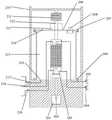
图1为本发明防堵塞的微生物温控注浆加固一体化三轴试验装置的结构示意图;Fig. 1 is the structural representation of the anti-clogging microbial temperature control grouting reinforcement integrated triaxial test device of the present invention;
图2为试验机构的结构示意图;Fig. 2 is the structural representation of test mechanism;
图3为试样本体的结构示意图;Fig. 3 is the structural representation of sample body;
图4为注浆机构的结构示意图;Fig. 4 is the structural representation of grouting mechanism;
图5为顶帽的结构示意图;Fig. 5 is the structural representation of top cap;
图6为底座的结构示意图;Fig. 6 is the structural representation of base;
其中,1、计算机;2、试验机构;3、注浆溶液箱;301、注浆溶液;302、流速控制器;303、第一温度控制器;304、第六阀门;305、第一连接管控制阀;306、第二连接管控制阀;4、废液箱;401、废液;402、第七阀门;403、第二温度控制器;404、流量控制器;405、第三连接管控制阀;406、第四连接管控制阀;5、气泵;6、反压压力控制器;7、孔隙水压力控制器;8、围压压力控制器;9、底座;10、顶帽;201、第一电机;202、第一连接杆;203、升降台;204、第一阀门;205、第二阀门;206、第一螺丝;207、第二螺丝;208、压力室温度控制器;209、顶盖;210、加载架;211、轴向压力传感器;212、轴力连接杆;213、顶盖活塞;214、排水孔;215、压力室;216、围压孔;217、第三阀门;218、第四阀门;220、第五阀门;221、反压孔;222、第三螺丝;223、底盖;224、第二空腔;225、第二连接管;226、下注浆孔;227、第一空腔;228、侧盖;229、第四螺丝;230、上注浆孔;231、孔隙水压力孔;232、透水石;233、试样件;234、乳胶膜;235、乳胶膜密封圈;236、第一连接管。Among them, 1. computer; 2. testing mechanism; 3. grouting solution tank; 301. grouting solution; 302. flow rate controller; 303. first temperature controller; 304. sixth valve; 305. first connecting pipe Control valve; 306, second connecting pipe control valve; 4, waste liquid tank; 401, waste liquid; 402, seventh valve; 403, second temperature controller; 404, flow controller; 405, third connecting pipe control Valve; 406, fourth connecting pipe control valve; 5, air pump; 6, back pressure controller; 7, pore water pressure controller; 8, confining pressure controller; 9, base; 10, top cap; 201, The first motor; 202, the first connecting rod; 203, the lifting platform; 204, the first valve; 205, the second valve; 206, the first screw; 207, the second screw; 208, the pressure chamber temperature controller; 209, Top cover; 210, loading frame; 211, axial pressure sensor; 212, axial force connecting rod; 213, top cover piston; 214, drainage hole; 215, pressure chamber; 216, confining pressure hole; 217, third valve; 218, the fourth valve; 220, the fifth valve; 221, the back pressure hole; 222, the third screw; 223, the bottom cover; 224, the second cavity; 225, the second connecting pipe; 226, the lower grouting hole; 227, the first cavity; 228, the side cover; 229, the fourth screw; 230, the upper grouting hole; 231, the pore water pressure hole; 232, the permeable stone; 233, the sample; 234, the latex film; 235, Latex film sealing ring; 236, the first connecting pipe.
具体实施方式Detailed ways
下面将结合本发明实施例中的附图,对本发明实施例中的技术方案进行清楚、完整地描述,显然,所描述的实施例仅仅是本发明一部分实施例,而不是全部的实施例。基于本发明中的实施例,本领域普通技术人员在没有做出创造性劳动前提下所获得的所有其他实施例,都属于本发明保护的范围。The following will clearly and completely describe the technical solutions in the embodiments of the present invention with reference to the accompanying drawings in the embodiments of the present invention. Obviously, the described embodiments are only some, not all, embodiments of the present invention. Based on the embodiments of the present invention, all other embodiments obtained by persons of ordinary skill in the art without making creative efforts belong to the protection scope of the present invention.
为使本发明的上述目的、特征和优点能够更加明显易懂,下面结合附图和具体实施方式对本发明作进一步详细的说明。In order to make the above objects, features and advantages of the present invention more comprehensible, the present invention will be further described in detail below in conjunction with the accompanying drawings and specific embodiments.
参照图1-6,本发明提供一种防堵塞的微生物温控注浆加固一体化三轴试验装置,包括试验机构2,试验机构2包括加载架210,加载架210内固接有压力室215,压力室215内设有试样本体,试样本体内设有试样件233,试样件233为土样,加载架210外固接并连通有注浆机构,注浆机构穿过加载架210和压力室215并与试样本体连通,加载架210外电性连接有监测机构。Referring to Figures 1-6, the present invention provides an anti-clogging microbial temperature-controlled grouting reinforcement integrated triaxial test device, including a
本发明解决了微生物注浆加固过程中注浆孔附近容易形成碳酸钙沉淀堵塞注浆孔的问题,同时省去试样微生物注浆加固完成后拆样与三轴试验装样的过程,从而解决了拆样和装样过程中对加固后试样产生扰动影响研究结果的问题,保证室内试验研究结果具有较高的准确性。The invention solves the problem that calcium carbonate precipitates are easily formed near the grouting hole to block the grouting hole during the microbial grouting reinforcement process, and at the same time saves the process of sample removal and triaxial test sample loading after the microbial grouting reinforcement is completed, thereby solving the problem of It solves the problem that the disturbance of the strengthened sample affects the research results during the sample removal and loading process, and ensures that the laboratory test research results have high accuracy.
进一步优化方案,加载架210内顶面固接有轴力连接杆212,轴力连接杆212穿过压力室215顶盖209并与试样本体的顶帽10固接,轴力连接杆212上安装有轴向压力传感器211,轴向压力传感器211位于压力室215的顶部,轴向压力传感器211与监测机构电性连接。To further optimize the scheme, the inner top surface of the
进一步优化方案,加载架210内底部固接有第一电机201,第一电机201固接有第一连接杆202,第一连接杆202远离第一电机201的一端固接有升降台203,升降台203和第一连接杆202的顶部位于压力室215内,升降台203与试样本体的底座9抵接。To further optimize the scheme, the bottom of the
升降台203通过第一连接杆202与第一电机201相连,通过电脑控制第一电机201实现升降台203的上升与下降,升降台203顶部凹槽可以与底座9通过第五螺丝固定连接,可实现对试样的应变控制三轴试验加载;加载架210顶部设置有轴力传感器通过轴力杆穿过试样顶盖209与试样顶帽10连接。轴力传感器的主要作用是进行三轴剪切过程中的轴力监测,轴力传感器通过轴力连接杆212穿过压力室215顶盖209与试样顶帽10相连,轴力传感器同时通过导线与计算机1相连,从而实现剪切过程中的轴力实时监测。The
进一步优化方案,顶帽10与试样本体的顶面固接,顶帽10内设有上注浆孔230,上注浆孔230与试样本体内连通,上注浆孔230通过第一连接管236与注浆机构连通,第一连接管236与顶帽10的外壁固接,顶帽10内设有孔隙水压力孔231,孔隙水压力孔231位于顶帽10远离第一连接管236的一侧,顶帽10内设有第一空腔227,第一空腔227分别与第一连接管236和上注浆孔230连通。To further optimize the scheme, the
第一空腔227用于在试样连接的上注浆孔230和第一空腔227之间设置格挡,防止产生的沉淀物堵塞孔口,影响后续试验,试验结束后可通过拆卸侧壁的第四螺丝229对第一空腔227内的沉淀物进行清洗。The
进一步优化方案,底座9顶面中心设有下注浆孔226,下注浆孔226与试样本体内连通,底座9内设有第二空腔224,下注浆孔226通过第二空腔224连通有第二连接管225,第二连接管225与注浆机构连通,第二连接管225有底座9的外侧固接,底座9远离第二连接管225的一侧设有反压孔221。To further optimize the scheme, a
进一步优化方案,底座9的底面可拆卸连接有底盖223,底盖223与升降台203的顶面抵接。In a further optimized solution, a
通过第三螺丝222可拆卸连接底盖223,方便试验结束拆下清洗内部的沉淀物,在注浆过程中产生的碳酸钙沉淀会在自身重力作用下沉淀于第二空腔224内部,不会在下注浆孔226口附近聚集,从而避免了沉淀物堵塞下注浆孔226,对微生物注浆效果产生影响,同时第二空腔224为圆柱形可为沉淀物提供较大的空间,边角设置为圆弧形方便清洗,上部为圆台形空心体同样达到避免侧壁附着沉淀对注浆产生严重影响与清洗方便的效果。The
进一步优化方案,试样本体包括乳胶膜234,乳胶膜234的顶部和底部分别设有乳胶膜密封圈235,乳胶膜密封圈235分别与顶帽10和底座9固接,乳胶膜234内设有所述试样件233,底座9和顶面之间依次放置有滤纸和透水石232。To further optimize the scheme, the sample body includes a
进一步优化方案,压力室215的顶部可拆卸连接有顶盖209,轴力连接杆212贯穿顶盖209,顶盖209的顶面安装有顶盖活塞213,轴力连接杆212贯穿顶盖活塞213,顶盖209上开设有排水孔214,顶盖209远离排水孔214的一侧固接有压力室温度控制器208。Further optimization scheme, the top of the
进一步优化方案,监测机构包括计算机1,计算机1电动连接有压力监测部,压力监测部包括与反压孔221电性连接的反压压力控制器6,反压压力控制器6与计算机1电型连接,孔隙水压力孔231电性连接有孔隙水压力控制器7,孔隙水压力控制器7与计算机1电型连接,压力室215内底面设有围压孔216,围压孔216电性连接有围压压力控制器8,围压压力控制器8与计算机1电性连接,计算机1与轴向压力传感器211电性连接。To further optimize the scheme, the monitoring mechanism includes a computer 1, and the computer 1 is electrically connected to a pressure monitoring part, and the pressure monitoring part includes a back
监测机构主要用于微生物注浆过程和三轴剪切试验过程中温度、注浆压力、流速和流量、空压、围压、轴力、位移等试验参数的监测与控制;孔隙水压力控制器7可进行逐渐过程中和三轴试验过程中的孔隙水压力监测;第一电机201主要用于为三轴剪切过程中的升降台203的上升与下降提供动力,通过导线与计算机1相连,并通过第一连接杆202与升降台203相连,控制升降台203上升与下降高度和速率,实现监测与控制剪切速率与剪切位移。The monitoring mechanism is mainly used for the monitoring and control of test parameters such as temperature, grouting pressure, flow rate and flow rate, air pressure, confining pressure, axial force, displacement, etc. during microbial grouting process and triaxial shear test; pore
进一步优化方案,注浆机构包括注浆溶液箱3,注浆溶液箱3中设有注浆溶液301,注浆溶液箱3分别与第一连接管236和第二连接管225连通,注浆溶液箱3的顶面固接有第一温度传感器,注浆溶液箱3连通有气泵5的一端,气泵5的另一端连通有废液箱4,废液箱4的顶部固接有第二温度控制器403。Further optimization scheme, the grouting mechanism comprises a
注浆溶液箱3主要用于盛放菌液、胶结液或二者一定比例的混合物,注浆溶液箱3与第一连接管236和第二连接管225之间通过第一管道连通,第一管道上设有流速控制器302,流速控制器302与计算机1电性连接,流速控制器302用于控制注浆溶液箱3溶液流动速度,即微生物注浆的流速,防止产生流速差从而对试样的饱和状态和应力状态产生严重影响,流速控制器302通过导线与计算机1相连,从而实现流速的监测与控制;第一温度传感器主要用于控制注浆溶液箱3的温度,维持温度在设置温度范围,注浆溶液箱3与气泵5之间设有第六阀门304,气泵5与废液箱4之间设有第七阀门402,气泵5主要用于给注浆溶液箱3和废液箱4施加气压,可分开施加不同压力,从而达到所需的注浆压力差;废液箱4通过第二管道分别与第一连接管236和第二连接管225连通,第二管道上设有流量控制器404,流量控制器404与计算机1电性连接,废液箱4主要用于盛放从试样本体中流出的废液401。The
在注浆溶液箱3和废液箱4与试样连接的管道设置双向阀门控制系统,双向阀门控制系统包括第一连接管控制阀305、第二连接管控制阀306、第三连接管控制阀405和第四连接管控制阀406,通过阀门控制可实现从试样注浆溶液301从试样底部流进从试样顶部流出,或者从试样顶部流入从试样底部流出,两种不同的注浆方向。A two-way valve control system is set on the pipes connecting the
实施时,试验机构2具体包括三轴系统加载架210,加载架210上部设置轴力传感器,轴力传感器通过轴力连接杆212与顶帽10连接传递轴力,通过数据线与计算机1相连进行数据保存与记录;加载架210底部设有升降台203、第一连接杆202和第一电机201,通过数据线与计算机1相连,控制三轴试验加载过程中的升降台203位移及升降速率;试样件233为圆柱形试样,顶部和底部按顺序设置滤纸、透水石232、顶帽10或底座9,并且试样件233通过乳胶膜234和密封密封于底座9和顶帽10之间,底座9通过第八螺丝固定于升降台203上,顶帽10通过轴力连接杆212与轴力传感器连接,底座9和顶帽10上的反压孔221、孔隙水压力孔231、上注浆孔230和下注浆孔226通过软管连接到相应压力控制器或注浆系统;压力室215为圆柱形,试验过程中需充满水,并通过围压压力控制器8和围压孔216对试样施加围压,压力室215侧壁通过设置的第一螺丝206与加载架210固定,顶盖209通过第二螺丝207与侧壁密封固定,并且顶盖209上设有排水孔214,试验过程中通过顶盖209上设置的压力室温度控制器208进行温度监测与控制,压力室温度控制器208通过监测压力室215环境温度与试验设置温度的差别从而选择性开启制热或制冷功能,控制调节压力室215温度,达到试验温控目的;During implementation, the
实施时,底座9为一种空心结构,当注浆溶液301从注浆系统第二连接管225流入底座9之后,进入第二空腔224,然后才经过下注浆孔226进入试样件233内部,在注浆过程中产生的沉淀会在重力作用下沉入内部空心底部,避免对下注浆孔226产生堵塞,试验结束后可取下底座9,拆掉第三螺丝222,打开底盖223,对底座9内部的沉淀物进行清洗,保证底座9内部连通管通畅;当注浆方向为自上而下流经土样时,流经土样后的溶液中沉淀物也会聚集于第二空腔224底部,避免对第二连接管225造成堵塞;During implementation, the base 9 is a hollow structure. After the
实施时,顶帽10为一种空心结构,注浆过程中流经顶帽10第一空腔227的过程中,有缓冲作用,溶液中的沉淀物会聚集于第一空腔227内,避免对第一连接管236或者上注浆孔230造成堵塞,影响试验注浆效果,试验结束后取下顶帽10,拆掉第四螺丝229,取下侧盖228,对顶帽10内部孔隙进行清洗,为后续试验重复使用顶帽10做准备;During implementation, the
实施时,注浆系统具体包括注浆溶液箱3、废液箱4、气泵5、流量控制器404、流苏控制器和连接管道阀门等,气泵5通过管道连接注浆溶液箱3和废液箱4,并通过数据线于计算机1相连,可分别控制施加于注浆溶液箱3和废液箱4的压力,两者的压力差即为注浆压力,注浆速度通过设置在管道上的流速控制器302和流量控制器404进行控制,同时注浆管道设置有双向控制阀门第一连接管控制阀305、第二连接管控制阀306、第三连接管控制阀405和第四连接管控制阀406,打开第一连接管控制阀305、第三连接管控制阀405,关闭第二连接管控制阀306、第四连接管控制阀406,注浆溶液301自下而上流经土样,打开第二连接管控制阀306、第四连接管控制阀406,关闭第一连接管控制阀305、第三连接管控制阀405,注浆溶液301自上而下流经土样,注浆过程中可实现不同试验需求;During implementation, the grouting system specifically includes a
实施时,通过数据线将反压压力控制器6、孔隙水压力控制器7、围压压力控制器8、轴力传感器、孔隙水压力传感器、第一电机201、压力室温度控制器208、注浆系统第一温度控制器303、第二温度控制器403、流量控制器404、流速控制器302和气泵5与计算机1进行连接,实现注浆和三轴试验过程中的监测与控制。During implementation, the
本试验装置的具体使用方法为:The specific use method of this test device is as follows:
1)完成全部前期准备工作,制样、装样、压力室215安装、压力室215加水、试样饱和、监测控制系统调试等注浆前准备工作;1) Complete all preparatory work, such as sample preparation, sample loading, installation of
2)首先关闭第一阀门204、第二阀门205、第四阀门218,打开第三阀门217、第五阀门220,通过计算机1控制反压压力控制器6和围压压力控制器8对试样施加围压和反压(反压不能超过围压),通过计算机1控制压力室温度控制器208、第一温度控制器303和第二温度控制器403使试样和注浆系统达到设计温度并维持稳定,达到稳定后关闭第五阀门220;2) First close the
3)根据试验方案,通过计算机1控制气压泵对注浆溶液箱3和废液箱4施加压力,打开第六阀门304和第七阀门402,且两个压力值均需大于反压且小于围压,他们的压力差即为注浆压力,当压力达到所需压力并稳定后,打开第一阀门204、第二阀门205、第一连接管控制阀305和第三连接管控制阀405,关闭第二连接管控制阀306和第四连接管控制阀406,让微生物注浆溶液301缓慢自下而上流经试样,对试样进行加固;3) According to the test plan, the computer 1 controls the air pump to apply pressure to the
4)注浆过程中通过计算机1控制流速控制器302和流量控制器404,使注浆孔和出浆口的流动速度相同,或者控制为试验设计流速大小,从而保持试样的压力状态和饱和状态稳定;4) During the grouting process, the computer 1 controls the
5)通过流速时间计算流量,当注浆溶液301全部充满试样孔隙后关闭注浆管和出浆管阀门,维持相应压力和温度稳定,根据试验设计养护一定时长;5) Calculate the flow rate based on the flow rate and time. When the
6)如果需要多次注浆重复步骤3~5;6) Repeat steps 3 to 5 if multiple grouting is required;
7)微生物加固注浆完成后,将注浆溶液箱3的注浆溶液301换成蒸馏水,用两倍试样孔隙体积的蒸馏水清洗试样中的残留注浆溶液301;7) After the microbial reinforcement grouting is completed, the
8)清洗完成后,关闭阀门第一阀门204和第二阀门205,维持试样温度和应力状态稳定,避免对试样产生扰动;8) After the cleaning is completed, close the
9)对试样进行反压饱和,根据三轴试验方案设计试验固结或者剪切过程所需的围压、反压,打开第五阀门220,通过计算机1和压力控制器设置将压力施加于试样件233上;9) Carry out backpressure saturation to the sample, design the confining pressure and backpressure required for the test consolidation or shearing process according to the triaxial test plan, open the
10)通过计算机1设置试验所需的剪切速率,控制第一电机201使升降台203按照设置剪切速率对试验进行剪切,完成试验三轴剪切试验;10) The shear rate required for the test is set by the computer 1, and the
11)试验结束后拆卸仪器与试样,并拆掉底座9的第三螺丝222,取下底盖223,对空心试样底座9内的沉淀物进行清洗,同样拆掉顶帽10侧壁的第四螺丝229,清洗空心试样顶帽10内的沉淀物;11) After the test is over, disassemble the instrument and the sample, remove the
12)整理仪器设备以备后续试验使用。12) Organize the instruments and equipment for subsequent tests.
在本发明的描述中,需要理解的是,术语“纵向”、“横向”、“上”、“下”、“前”、“后”、“左”、“右”、“竖直”、“水平”、“顶”、“底”、“内”、“外”等指示的方位或位置关系为基于附图所示的方位或位置关系,仅是为了便于描述本发明,而不是指示或暗示所指的装置或元件必须具有特定的方位、以特定的方位构造和操作,因此不能理解为对本发明的限制。In describing the present invention, it should be understood that the terms "longitudinal", "transverse", "upper", "lower", "front", "rear", "left", "right", "vertical", The orientations or positional relationships indicated by "horizontal", "top", "bottom", "inner", "outer", etc. are based on the orientations or positional relationships shown in the drawings, and are only for the convenience of describing the present invention, rather than indicating or It should not be construed as limiting the invention by implying that a referenced device or element must have a particular orientation, be constructed, and operate in a particular orientation.
以上所述的实施例仅是对本发明的优选方式进行描述,并非对本发明的范围进行限定,在不脱离本发明设计精神的前提下,本领域普通技术人员对本发明的技术方案做出的各种变形和改进,均应落入本发明权利要求书确定的保护范围内。The above-mentioned embodiments are only to describe the preferred mode of the present invention, not to limit the scope of the present invention. Without departing from the design spirit of the present invention, those skilled in the art may make various Variations and improvements should fall within the scope of protection defined by the claims of the present invention.
Claims (10)
Translated fromChinesePriority Applications (1)
| Application Number | Priority Date | Filing Date | Title |
|---|---|---|---|
| CN202211251954.0ACN115406738B (en) | 2022-10-13 | 2022-10-13 | An anti-clogging integrated triaxial test device for microbial temperature-controlled grouting reinforcement |
Applications Claiming Priority (1)
| Application Number | Priority Date | Filing Date | Title |
|---|---|---|---|
| CN202211251954.0ACN115406738B (en) | 2022-10-13 | 2022-10-13 | An anti-clogging integrated triaxial test device for microbial temperature-controlled grouting reinforcement |
Publications (2)
| Publication Number | Publication Date |
|---|---|
| CN115406738Atrue CN115406738A (en) | 2022-11-29 |
| CN115406738B CN115406738B (en) | 2023-05-23 |
Family
ID=84168848
Family Applications (1)
| Application Number | Title | Priority Date | Filing Date |
|---|---|---|---|
| CN202211251954.0AActiveCN115406738B (en) | 2022-10-13 | 2022-10-13 | An anti-clogging integrated triaxial test device for microbial temperature-controlled grouting reinforcement |
Country Status (1)
| Country | Link |
|---|---|
| CN (1) | CN115406738B (en) |
Cited By (3)
| Publication number | Priority date | Publication date | Assignee | Title |
|---|---|---|---|---|
| CN117554149A (en)* | 2023-11-16 | 2024-02-13 | 北京建筑大学 | Glutinous rice slurry and urease combined calcium carbonate reinforced soil sample preparation system and method |
| CN117664683A (en)* | 2023-11-29 | 2024-03-08 | 水利部交通运输部国家能源局南京水利科学研究院 | A microorganism-reinforced sand hollow cylindrical sample preparation device and its use method |
| CN119688404A (en)* | 2024-11-16 | 2025-03-25 | 重庆大学 | Microorganism reinforcement large-scale model test method and test device |
Citations (14)
| Publication number | Priority date | Publication date | Assignee | Title |
|---|---|---|---|---|
| CN103389249A (en)* | 2013-07-18 | 2013-11-13 | 河海大学 | Device and method for clay core wall hydraulic fracturing experiments |
| CN203981507U (en)* | 2014-06-19 | 2014-12-03 | 河海大学 | A New Plane Strain Consolidation Test Device |
| CN206862784U (en)* | 2017-06-19 | 2018-01-09 | 中国科学院武汉岩土力学研究所 | A kind of indoor Triaxial tester for testing sand slip casting setting strength |
| CN109596814A (en)* | 2019-01-10 | 2019-04-09 | 中山大学 | The layer of sand three-dimensional grouting test device and its test method of analog actual condition |
| CN109752248A (en)* | 2019-01-22 | 2019-05-14 | 北京交通大学 | Visual simulation test device and method for soil mud-water splitting and extension process |
| CN209979386U (en)* | 2019-01-22 | 2020-01-21 | 北京交通大学 | Visual Simulation Test Device for Soil Slurry Splitting and Spreading Process |
| CN111189756A (en)* | 2020-01-10 | 2020-05-22 | 中国矿业大学 | A broken rock mass-hydro-dynamic coupling test system |
| CN111208047A (en)* | 2020-01-10 | 2020-05-29 | 中国矿业大学 | Test method capable of simulating permeability of fractured rock mass under complex disturbance condition |
| CN210665305U (en)* | 2019-04-26 | 2020-06-02 | 温州大学 | Embedded geotechnical triaxial instrument |
| US20210055234A1 (en)* | 2019-08-22 | 2021-02-25 | Shandong University | Miniature temperature-controlled triaxial tester for testing unsaturated soil suitable for micro-computed tomography (ct) scanning and method thereby |
| AU2020104161A4 (en)* | 2020-12-17 | 2021-03-04 | Nanjing Technology University | Anisotropic resonant column system and method for stable and accurate temperature control |
| WO2021143229A1 (en)* | 2020-01-17 | 2021-07-22 | 同济大学 | Test system for measuring gas permeation parameters of ultra-low permeability medium in multi-field and multi-phase coupling conditions |
| WO2022142671A1 (en)* | 2021-01-04 | 2022-07-07 | 青岛理工大学 | Triaxial shear and seepage integrated experimental method and device for hydrate-bearing sediment |
| CN217443058U (en)* | 2022-05-11 | 2022-09-16 | 天津大学 | Low-stress triaxial test improves device |
- 2022
- 2022-10-13CNCN202211251954.0Apatent/CN115406738B/enactiveActive
Patent Citations (14)
| Publication number | Priority date | Publication date | Assignee | Title |
|---|---|---|---|---|
| CN103389249A (en)* | 2013-07-18 | 2013-11-13 | 河海大学 | Device and method for clay core wall hydraulic fracturing experiments |
| CN203981507U (en)* | 2014-06-19 | 2014-12-03 | 河海大学 | A New Plane Strain Consolidation Test Device |
| CN206862784U (en)* | 2017-06-19 | 2018-01-09 | 中国科学院武汉岩土力学研究所 | A kind of indoor Triaxial tester for testing sand slip casting setting strength |
| CN109596814A (en)* | 2019-01-10 | 2019-04-09 | 中山大学 | The layer of sand three-dimensional grouting test device and its test method of analog actual condition |
| CN109752248A (en)* | 2019-01-22 | 2019-05-14 | 北京交通大学 | Visual simulation test device and method for soil mud-water splitting and extension process |
| CN209979386U (en)* | 2019-01-22 | 2020-01-21 | 北京交通大学 | Visual Simulation Test Device for Soil Slurry Splitting and Spreading Process |
| CN210665305U (en)* | 2019-04-26 | 2020-06-02 | 温州大学 | Embedded geotechnical triaxial instrument |
| US20210055234A1 (en)* | 2019-08-22 | 2021-02-25 | Shandong University | Miniature temperature-controlled triaxial tester for testing unsaturated soil suitable for micro-computed tomography (ct) scanning and method thereby |
| CN111208047A (en)* | 2020-01-10 | 2020-05-29 | 中国矿业大学 | Test method capable of simulating permeability of fractured rock mass under complex disturbance condition |
| CN111189756A (en)* | 2020-01-10 | 2020-05-22 | 中国矿业大学 | A broken rock mass-hydro-dynamic coupling test system |
| WO2021143229A1 (en)* | 2020-01-17 | 2021-07-22 | 同济大学 | Test system for measuring gas permeation parameters of ultra-low permeability medium in multi-field and multi-phase coupling conditions |
| AU2020104161A4 (en)* | 2020-12-17 | 2021-03-04 | Nanjing Technology University | Anisotropic resonant column system and method for stable and accurate temperature control |
| WO2022142671A1 (en)* | 2021-01-04 | 2022-07-07 | 青岛理工大学 | Triaxial shear and seepage integrated experimental method and device for hydrate-bearing sediment |
| CN217443058U (en)* | 2022-05-11 | 2022-09-16 | 天津大学 | Low-stress triaxial test improves device |
Cited By (3)
| Publication number | Priority date | Publication date | Assignee | Title |
|---|---|---|---|---|
| CN117554149A (en)* | 2023-11-16 | 2024-02-13 | 北京建筑大学 | Glutinous rice slurry and urease combined calcium carbonate reinforced soil sample preparation system and method |
| CN117664683A (en)* | 2023-11-29 | 2024-03-08 | 水利部交通运输部国家能源局南京水利科学研究院 | A microorganism-reinforced sand hollow cylindrical sample preparation device and its use method |
| CN119688404A (en)* | 2024-11-16 | 2025-03-25 | 重庆大学 | Microorganism reinforcement large-scale model test method and test device |
Also Published As
| Publication number | Publication date |
|---|---|
| CN115406738B (en) | 2023-05-23 |
Similar Documents
| Publication | Publication Date | Title |
|---|---|---|
| CN115406738A (en) | An anti-clogging integrated triaxial test device for microbial temperature-controlled grouting reinforcement | |
| CN105823717B (en) | A kind of simple pressure chamber model of slurry shield and its application method | |
| CN109323902A (en) | A kind of test device and test method for microbial cementation reinforcement of loess sample | |
| CN104483240A (en) | A large-scale simulation device for simulating the vertical migration of pollutants in aquifers | |
| CN105484298B (en) | A microbial reinforcement grouting maintenance test device | |
| CN106525526B (en) | A method for measuring the high-pressure water injection and radial gas permeability of raw coal containing gas | |
| CN104251790A (en) | Self-water injection type rock and soil sample saturator | |
| CN115629182B (en) | Microorganism grouting reinforcement device considering temperature and confining pressure and use method | |
| CN202956329U (en) | Indoor grouting test device under simulated complex stress | |
| CN106353480A (en) | Method for testing microbe cemented fine-grained soil under negative pressure | |
| CN104614297A (en) | Geotechnical composite drainage material filter membrane horizontal seepage clogging discounting test device and test method thereof | |
| CN104677804B (en) | Floating ball lever automatic flow control determines head saturated hydraulic conductivity in soil batch analyzer | |
| CN106153860A (en) | A kind of device and method of one-dimensional microorganism grouting and reinforcing silt test | |
| CN206209420U (en) | A kind of experimental rig of use geneva bottle method controlling groundwater level balance | |
| CN114659939A (en) | Pollutant migration soil column device for plastic concrete and test method thereof | |
| CN103336105B (en) | Soft foundation treatment experiment device and method | |
| CN102854028B (en) | Plugging testing apparatus for water prevention and drainage system of undersea tunnel | |
| CN106290100A (en) | A kind of soil body biology consolidates non-disturbance permeability and intensity detection assay device | |
| CN214895279U (en) | Test device for simulating earthen site cracks through microorganism grouting and curing | |
| CN106053312B (en) | Characterize the pore structure Spatio-temporal Evolution experimental rig and its application method of porous media | |
| CN111735702A (en) | A test device and test method for microbial gelation repairing natural loess joints | |
| CN102374958B (en) | Test apparatus for studying seepage and scouring characteristics of soil body | |
| CN205276337U (en) | Grout maintenance test device is consolidated to microorganism | |
| CN221485155U (en) | Indoor simulated penetration grouting test device | |
| CN109594980B (en) | A visual experimental device for simulating the law of dynamic sand plugging in gravel layers |
Legal Events
| Date | Code | Title | Description |
|---|---|---|---|
| PB01 | Publication | ||
| PB01 | Publication | ||
| SE01 | Entry into force of request for substantive examination | ||
| SE01 | Entry into force of request for substantive examination | ||
| GR01 | Patent grant | ||
| GR01 | Patent grant |