CN115397629A - Off-line simulation system - Google Patents
Off-line simulation systemDownload PDFInfo
- Publication number
- CN115397629A CN115397629ACN202180025317.9ACN202180025317ACN115397629ACN 115397629 ACN115397629 ACN 115397629ACN 202180025317 ACN202180025317 ACN 202180025317ACN 115397629 ACN115397629 ACN 115397629A
- Authority
- CN
- China
- Prior art keywords
- workpiece
- unit
- virtual space
- teaching
- camera
- Prior art date
- Legal status (The legal status is an assumption and is not a legal conclusion. Google has not performed a legal analysis and makes no representation as to the accuracy of the status listed.)
- Pending
Links
Images


Classifications
- B—PERFORMING OPERATIONS; TRANSPORTING
- B25—HAND TOOLS; PORTABLE POWER-DRIVEN TOOLS; MANIPULATORS
- B25J—MANIPULATORS; CHAMBERS PROVIDED WITH MANIPULATION DEVICES
- B25J9/00—Programme-controlled manipulators
- B25J9/16—Programme controls
- B25J9/1656—Programme controls characterised by programming, planning systems for manipulators
- B25J9/1671—Programme controls characterised by programming, planning systems for manipulators characterised by simulation, either to verify existing program or to create and verify new program, CAD/CAM oriented, graphic oriented programming systems
- B—PERFORMING OPERATIONS; TRANSPORTING
- B25—HAND TOOLS; PORTABLE POWER-DRIVEN TOOLS; MANIPULATORS
- B25J—MANIPULATORS; CHAMBERS PROVIDED WITH MANIPULATION DEVICES
- B25J9/00—Programme-controlled manipulators
- B25J9/16—Programme controls
- B25J9/1679—Programme controls characterised by the tasks executed
- B25J9/1692—Calibration of manipulator
- B—PERFORMING OPERATIONS; TRANSPORTING
- B25—HAND TOOLS; PORTABLE POWER-DRIVEN TOOLS; MANIPULATORS
- B25J—MANIPULATORS; CHAMBERS PROVIDED WITH MANIPULATION DEVICES
- B25J9/00—Programme-controlled manipulators
- B25J9/16—Programme controls
- B25J9/1694—Programme controls characterised by use of sensors other than normal servo-feedback from position, speed or acceleration sensors, perception control, multi-sensor controlled systems, sensor fusion
- B25J9/1697—Vision controlled systems
- G—PHYSICS
- G05—CONTROLLING; REGULATING
- G05B—CONTROL OR REGULATING SYSTEMS IN GENERAL; FUNCTIONAL ELEMENTS OF SUCH SYSTEMS; MONITORING OR TESTING ARRANGEMENTS FOR SUCH SYSTEMS OR ELEMENTS
- G05B19/00—Programme-control systems
- G05B19/02—Programme-control systems electric
- G05B19/18—Numerical control [NC], i.e. automatically operating machines, in particular machine tools, e.g. in a manufacturing environment, so as to execute positioning, movement or co-ordinated operations by means of programme data in numerical form
- G05B19/4155—Numerical control [NC], i.e. automatically operating machines, in particular machine tools, e.g. in a manufacturing environment, so as to execute positioning, movement or co-ordinated operations by means of programme data in numerical form characterised by programme execution, i.e. part programme or machine function execution, e.g. selection of a programme
- G—PHYSICS
- G05—CONTROLLING; REGULATING
- G05B—CONTROL OR REGULATING SYSTEMS IN GENERAL; FUNCTIONAL ELEMENTS OF SUCH SYSTEMS; MONITORING OR TESTING ARRANGEMENTS FOR SUCH SYSTEMS OR ELEMENTS
- G05B19/00—Programme-control systems
- G05B19/02—Programme-control systems electric
- G05B19/42—Recording and playback systems, i.e. in which the programme is recorded from a cycle of operations, e.g. the cycle of operations being manually controlled, after which this record is played back on the same machine
- G05B19/427—Teaching successive positions by tracking the position of a joystick or handle to control the positioning servo of the tool head, leader-follower control
- G—PHYSICS
- G05—CONTROLLING; REGULATING
- G05B—CONTROL OR REGULATING SYSTEMS IN GENERAL; FUNCTIONAL ELEMENTS OF SUCH SYSTEMS; MONITORING OR TESTING ARRANGEMENTS FOR SUCH SYSTEMS OR ELEMENTS
- G05B2219/00—Program-control systems
- G05B2219/30—Nc systems
- G05B2219/39—Robotics, robotics to robotics hand
- G05B2219/39014—Match virtual world with real world
- G—PHYSICS
- G05—CONTROLLING; REGULATING
- G05B—CONTROL OR REGULATING SYSTEMS IN GENERAL; FUNCTIONAL ELEMENTS OF SUCH SYSTEMS; MONITORING OR TESTING ARRANGEMENTS FOR SUCH SYSTEMS OR ELEMENTS
- G05B2219/00—Program-control systems
- G05B2219/30—Nc systems
- G05B2219/50—Machine tool, machine tool null till machine tool work handling
- G05B2219/50391—Robot
Landscapes
- Engineering & Computer Science (AREA)
- Robotics (AREA)
- Mechanical Engineering (AREA)
- Physics & Mathematics (AREA)
- General Physics & Mathematics (AREA)
- Automation & Control Theory (AREA)
- Human Computer Interaction (AREA)
- Manufacturing & Machinery (AREA)
- Numerical Control (AREA)
- Manipulator (AREA)
Abstract
Translated fromChinese
Description
Translated fromChinese技术领域technical field
本发明涉及离线模拟系统。The present invention relates to off-line simulation systems.
背景技术Background technique
在以机器人对工件进行预定动作的方式进行了示教的情况下,若示教时的工件的位置与机器人动作时的工件的位置偏离,则机器人不能对于工件适当地动作。在该情况下,已知有通过照相机等视觉传感器检测工件,对工件位置的偏移量进行视觉校正的方法(例如,参照专利文献1)。为了适当地进行这样的视觉校正的设定,作业者能够实际使机器人动作,实习视觉校正的设定。When the teaching is performed so that the robot performs a predetermined movement on the workpiece, if the position of the workpiece at the time of teaching deviates from the position of the workpiece at the time of robot operation, the robot cannot properly operate on the workpiece. In this case, there is known a method of visually correcting the displacement amount of the workpiece by detecting the workpiece with a visual sensor such as a camera (for example, refer to Patent Document 1). In order to appropriately set such vision correction, the operator can actually operate the robot and practice the setting of vision correction.
现有技术文献prior art literature
专利文献patent documents
专利文献1:日本特开2006-260271号公报Patent Document 1: Japanese Patent Laid-Open No. 2006-260271
发明内容Contents of the invention
发明所要解决的课题The problem to be solved by the invention
但是,在实际使机器人动作,实习视觉校正的设定的情况下,需要准备用于实习的设备,耗费设备费用。另外,坐标系等的设定难以直观地确认是否适当地进行设定,因此有可能无法适当地进行设定而产生干扰等。因此,期望高效地进行视觉校正的实习。However, in the case of actually operating the robot and practicing the setting of the vision correction, it is necessary to prepare equipment for the training, which costs equipment costs. In addition, since it is difficult to visually confirm whether the setting of the coordinate system or the like is appropriate, there is a possibility that the setting may not be performed properly, causing disturbance or the like. Therefore, it is desired to efficiently perform vision correction training.
用于解决课题的手段means to solve the problem
本公开的离线模拟系统是用于实习视觉校正的离线模拟系统,具备:信息处理装置,其能够显示虚拟空间的图像;以及示教装置,其以能够通信的方式与所述信息处理装置连接。所述示教装置具有:虚拟空间生成部,其生成所述虚拟空间的图像;示教部,其在所述虚拟空间内配置机器人和工件,以所述机器人对所述工件进行预定的动作的方式进行示教;照相机配置部,其在所述虚拟空间内,在所述工件进入视野内的位置配置照相机;视觉校正部,其在所述工件的位置被移动后,基于由所述照相机拍摄到的摄像图像,对所述预定的动作进行视觉校正;以及校正确认部,其确认所述预定的动作被适当地进行视觉校正。An offline simulation system of the present disclosure is an offline simulation system for practicing vision correction, and includes: an information processing device capable of displaying images of a virtual space; and a teaching device communicably connected to the information processing device. The teaching device includes: a virtual space generating unit that generates an image of the virtual space; a teaching unit that arranges a robot and a workpiece in the virtual space, and uses the robot to perform a predetermined movement on the workpiece. teaching in the same manner; a camera arrangement unit, which arranges a camera at a position where the workpiece enters the field of view in the virtual space; a vision correction unit, after the position of the workpiece is moved, based on the visually correcting the predetermined movement; and a correction confirming unit that confirms that the predetermined movement is properly visually corrected.
发明效果Invention effect
根据本发明,能够高效地进行视觉校正的实习。According to the present invention, training for vision correction can be efficiently performed.
附图说明Description of drawings
图1是表示本实施方式的视觉校正实习系统的结构的图。FIG. 1 is a diagram showing the configuration of a vision correction training system according to this embodiment.
图2是表示头戴式显示器的结构的图。FIG. 2 is a diagram showing a configuration of a head-mounted display.
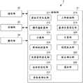
图3是表示示教装置的结构的图。FIG. 3 is a diagram showing the configuration of the teaching device.
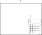
图4是表示配置于虚拟空间内的示教操作盘的图。FIG. 4 is a diagram showing a teaching pendant arranged in a virtual space.
图5是表示配置于虚拟空间内的工件以及机器人的图。FIG. 5 is a diagram showing workpieces and robots arranged in a virtual space.
图6是表示配置于虚拟空间内的照相机的图。FIG. 6 is a diagram showing cameras arranged in a virtual space.
图7是表示配置于虚拟空间内的坐标系的图。FIG. 7 is a diagram showing a coordinate system arranged in a virtual space.
图8是表示视觉校正实习系统的处理的流程图。Fig. 8 is a flowchart showing the processing of the vision correction training system.
具体实施方式Detailed ways
以下,对本发明的实施方式的一例进行说明。Hereinafter, an example of the embodiment of the present invention will be described.
图1是表示本实施方式的视觉校正实习系统100的结构的图。视觉校正实习系统100是用于为了在实际的机器人中适当地执行视觉校正而由机器人的操作员在虚拟空间内实习视觉校正的离线模拟系统的一例。如图1所示,视觉校正实习系统100具备头戴式显示器1和示教装置2。FIG. 1 is a diagram showing the configuration of a vision
头戴式显示器1佩戴于操作员的头部,显示虚拟现实(VR(Virtual Reality))的影像。操作员一边观察头戴式显示器1所显示的虚拟现实的影像,一边实习(模拟)视觉校正,从而能够提高对影像世界的沉浸感,能够高效地进行实习。头戴式显示器1通过有线或无线通信与示教装置2连接。另外,头戴式显示器1也可以内置于示教装置2。另外,本实施方式的视觉校正实习系统100使用头戴式显示器1作为信息处理装置进行说明,但并不限定于此,信息处理装置例如也可以是台式计算机、膝上型计算机、平板电脑、智能手机等。The head-mounted display 1 is worn on the operator's head, and displays a virtual reality (VR (Virtual Reality)) image. The operator can practice (simulate) vision correction while viewing the virtual reality video displayed on the head-mounted display 1 , thereby enhancing the sense of immersion in the video world and effectively practicing. The head-mounted display 1 is connected to the
示教装置2生成虚拟现实的影像,向头戴式显示器1发送虚拟现实的影像。示教装置2通过有线或无线通信与头戴式显示器1连接。另外,示教装置2也可以内置于头戴式显示器1。示教装置2也可以与实际的机器人的控制装置连接,能够通过与控制装置连接的示教操作盘进行操作。机器人的控制装置也可以是虚拟的装置。The
图2是表示头戴式显示器1的结构的图。如图2所示,头戴式显示器1具备控制部11、输入接口12、输出接口13、显示面板14、通信部15、存储部16以及姿势传感器17。FIG. 2 is a diagram showing the configuration of the head-mounted display 1 . As shown in FIG. 2 , the head-mounted display 1 includes a control unit 11 , an
控制部11是CPU(Central Processing Unit:中央处理单元)等处理器。控制部11通过执行存储于存储部16的程序,对图像信号、传感器信号等信号、命令、数据等进行处理以及输出。The control unit 11 is a processor such as a CPU (Central Processing Unit: Central Processing Unit). The control unit 11 processes and outputs signals such as image signals and sensor signals, commands, data, and the like by executing the programs stored in the
输入接口12接受来自用户的操作信号、设定信号,并提供给控制部11。The
输出接口13从控制部11接收图像信号,并显示于显示面板14。The
通信部15是用于经由网络在与示教装置2之间进行通信的通信接口。通信部15包含用于执行通信的处理器、连接器、电路、天线等。通信部15对从示教装置2接收到的通信信号进行预定的处理而取得数据,并将取得的数据输入到控制部11。另外,通信部15对从控制部11输入的数据进行预定的处理而生成通信信号,并将生成的通信信号发送至示教装置2。The
存储部16是存储OS(Operating System:操作系统)、应用程序等的ROM(Read OnlyMemory:只读存储器)、RAM(Random Access Memory:随机存取存储器)、存储其他各种信息的硬盘驱动器或SSD(Solid State Drive:固态驱动器)等存储装置。The
姿势传感器17检测头戴式显示器1的位置信息、头戴式显示器1的旋转角、倾斜等的姿势信息。姿势传感器17通过组合陀螺仪传感器、加速度传感器、角加速度传感器等来实现。头戴式显示器1也可以使用将3轴地磁传感器、3轴加速度传感器以及3轴陀螺仪传感器中的至少1个以上组合而成的运动传感器,检测用户头部的前后、左右、上下的运动。The
图3是表示示教装置2的结构的图。如图3所示,示教装置2具备控制部21、通信部22、存储部23以及操作部24。FIG. 3 is a diagram showing the configuration of the
控制部21是CPU等处理器,通过执行存储于存储部23中的程序来实现各种功能。The
控制部21具备虚拟空间生成部211、操作盘配置部212、示教部213、照相机配置部214、光学条件设定部215、坐标系设定部216、坐标系确认部217、工件检测部218、基准位置设定部219、计算部220、视觉校正部221、校正确认部222以及通知部223。The
通信部22是用于经由网络在与头戴式显示器1之间进行通信的通信接口。通信部22包含用于执行通信的处理器、连接器、电路、天线等。通信部22对从头戴式显示器1接收到的通信信号进行预定的处理而取得数据,并将取得的数据输入到控制部21。另外,通信部22对从控制部21输入的数据进行预定的处理而生成通信信号,并将生成的通信信号发送到头戴式显示器1。The
存储部23是存储OS、应用程序等的ROM、RAM、存储其他各种信息的硬盘驱动器或SSD等存储装置。The
操作部24是键盘、指示设备等,接受来自操作员的操作信号和设定信号,并提供给控制部21。The
接着,参照图4至图7对在虚拟空间内实习视觉校正的动作进行说明。Next, the operation of practicing vision correction in the virtual space will be described with reference to FIGS. 4 to 7 .
图4至图7是表示配置在虚拟空间内的对象的图。具体而言,图4是表示配置于虚拟空间V内的示教操作盘B的图。图5是表示配置于虚拟空间V内的工件W以及机器人R的图。图6是表示配置于虚拟空间V内的照相机C的图。图7是表示配置于虚拟空间V内的坐标系S的图。4 to 7 are diagrams showing objects arranged in a virtual space. Specifically, FIG. 4 is a diagram showing the teaching pendant B arranged in the virtual space V. As shown in FIG. FIG. 5 is a diagram showing a workpiece W and a robot R arranged in a virtual space V. As shown in FIG. FIG. 6 is a diagram showing cameras C arranged in the virtual space V. As shown in FIG. FIG. 7 is a diagram showing a coordinate system S arranged in a virtual space V. As shown in FIG.
首先,虚拟空间生成部211生成虚拟空间的图像。具体而言,如图4所示,虚拟空间生成部211使用由姿势传感器17检测出的姿势信息,生成用于实习机器人的视觉校正的虚拟空间V的图像。虚拟空间V如后述那样能够显示示教操作盘、机器人、工件、照相机、坐标系等对象的图像。操作员一边观察在头戴式显示器1的显示面板14上显示的虚拟空间V的图像,一边实习(模拟)视觉校正。另外,由于使用由姿势传感器17检测出的姿势信息,因此虚拟空间生成部211能够生成反映了操作员的头部动作的虚拟空间V的图像。First, the virtual space generating unit 211 generates an image of a virtual space. Specifically, as shown in FIG. 4 , the virtual space generation unit 211 generates an image of the virtual space V used for visual correction of the training robot using the posture information detected by the
如图3所示,操作盘配置部212在虚拟空间V内配置机器人的示教操作盘B。示教操作盘B具有:虚拟的输入部,其由用于向机器人示教动作的键等构成;以及虚拟的显示部,其显示所示教的动作的命令、由照相机拍摄到的图像等。As shown in FIG. 3 , the operation
操作员通过操作部24对显示于虚拟空间V内的示教操作盘B进行操作,从而执行用于进行视觉校正的示教和设定等。The operator operates the teaching operation panel B displayed in the virtual space V through the
如图5所示,示教部213在虚拟空间V内配置机器人R以及工件W,以机器人R对工件W进行预定的动作的方式进行示教。As shown in FIG. 5 , the
具体而言,示教部213的操作员在虚拟空间V内配置机器人R以及工件W的对象。示教部213能够使用预先存储于存储部23的CAD数据将机器人R以及工件W的对象配置于虚拟空间V内。在此,机器人R的预定动作例如包含通过机器人R把持工件W等机器人R相对于工件W的任意的动作。Specifically, the operator of the
然后,示教部213通过操作员对示教操作盘B进行操作来设定机器人R的动作程序,以机器人R对工件W进行预定的动作的方式进行示教。Then, the
接着,如图6所示,照相机配置部214在虚拟空间V内,在工件W进入照相机C的视野内的位置配置照相机C。Next, as shown in FIG. 6 , the
由照相机C拍摄到的拍摄图像显示于示教操作盘B。操作员还能够一边观察在示教操作盘B上显示的拍摄图像一边对照相机C的位置进行微调。另外,由照相机C拍摄到的拍摄图像不仅可以显示在示教操作盘B上,还可以显示在虚拟空间V内的其他窗口中。The image captured by the camera C is displayed on the teaching pendant B. The operator can also fine-tune the position of the camera C while viewing the captured image displayed on the teaching pendant B. In addition, the captured image captured by the camera C may be displayed not only on the teaching pendant B but also on other windows in the virtual space V. FIG.
光学条件设定部215设定配置在虚拟空间V内的照相机C的光学条件。具体而言,光学条件设定部215能够模拟照相机C的镜头的光圈、曝光时间、镜头的焦点等。例如,光学条件设定部215通过变更照相机C的镜头的光圈、曝光时间等,能够变更由照相机C拍摄到的拍摄图像的亮度。另外,光学条件设定部215通过使镜头的焦点对准,使由照相机C拍摄到的拍摄图像鲜明。The optical
照相机C和光学条件设定部215优选在虚拟空间上再现与实际的照相机和镜头相同的部件。The camera C and the optical
坐标系设定部216设定用于视觉校正的坐标系。例如,坐标系设定部216进行为了照相机C的校准而取代工件W配置的点阵图夹具的设置位置的设定、用于决定校正面的坐标系的设定。The coordinate
在照相机C的校准中,通过由照相机C拍摄操作员设定了设置位置的点阵图夹具,能够将由照相机C拍摄到的拍摄图像上的工件W的位置信息转换为成为机器人R的动作基准的坐标系中的位置信息。In the calibration of the camera C, the position information of the workpiece W on the captured image captured by the camera C can be converted into the position information of the workpiece W that becomes the movement reference of the robot R by the camera C capturing the bitmap jig whose installation position has been set by the operator. Position information in a coordinate system.
在使用了2维照相机的视觉校正中,为了测量在所设定的校正面上的工件W的偏移量而进行校正,操作员设定确定校正面的坐标系。如图7所示,坐标系设定部216作为用于进行视觉校正的坐标系,在虚拟空间V内设定坐标系S,在虚拟空间V内配置坐标系S。由坐标系S决定的校正面用于测量工件W的偏移量并进行校正。In vision calibration using a two-dimensional camera, in order to perform calibration by measuring the amount of displacement of the workpiece W on the set calibration plane, the operator sets a coordinate system that defines the calibration plane. As shown in FIG. 7 , the coordinate
坐标系确认部217在为了照相机C的校准而取代工件W配置的点阵图夹具的位置没有被适当设定的情况下,使通知部223显示表示点阵图夹具的位置未被适当地设定的警报。由此,操作员能够学到适当地设定坐标系的方法。When the position of the dot pattern jig arranged instead of the workpiece W for the calibration of the camera C is not properly set, the coordinate
另外,坐标系确认部217在通过照相机C的校准求出的机器人R和照相机C的位置关系与配置于虚拟空间V内的机器人R和照相机C的位置关系不同的情况下,通过通知部223显示表示机器人R以及照相机C的位置未被适当地设定的警报。In addition, when the positional relationship between the robot R and the camera C obtained through the calibration of the camera C is different from the positional relationship between the robot R and the camera C arranged in the virtual space V, the coordinate
工件检测部218示教工件W的模型化后的模型图案,使用模型图案从通过照相机C拍摄工件W的拍摄图像中检测工件W的位置。基准位置设定部219将由工件检测部218在拍摄图像中检测出工件W的位置设定为工件W的基准位置。The
工件检测部218在工件W的位置移动后,再次从拍摄图像检测工件W的位置。然后,计算部220计算由工件检测部218检测出的工件的位置与基准位置的偏移量。The
视觉校正部221在工件W的位置移动后,基于由照相机C拍摄到的拍摄图像,对预定的动作进行视觉校正。具体而言,视觉校正部221按照基于由照相机C拍摄到的拍摄图像计算出的偏移量对机器人R的示教位置进行校正,以对工件W进行预定的动作的方式进行示教。The
校正确认部222确认对于工件W适当地视觉校正了预定的动作。例如,校正确认部222在工件W的位置移动后,在虚拟空间V内知道工件W的移动量,因此,在根据由照相机C拍摄到的拍摄图像中检测出的工件W的位置计算出视觉校正量时,比较工件W的移动量和视觉校正量,并能够确认是否适当地进行视觉校正。The
例如,在未适当地进行视觉校正的情况下,在工件W的位置移动之后,机器人R无法对工件W适当地完成预定的动作。因此,校正确认部222通过通知部223显示表示未适当地进行视觉校正的警报。For example, if the vision correction is not properly performed, the robot R cannot properly perform a predetermined operation on the workpiece W after the workpiece W is moved. Therefore, the
通知部223在虚拟空间V内显示警报。具体而言,如上所述,在坐标系S不是为了进行视觉校正的适当位置的情况下、或未适当地进行视觉校正的情况下,通知部223在虚拟空间V内的其他窗口中显示警报。The
这样,由于在虚拟空间V内配置有机器人R、工件W、照相机C、坐标系S等,因此操作员能够在视觉上确认是否适当地进行坐标系的设定、视觉校正等。而且,系统也能够在设定不适当的情况下显示警报。之后,操作员能够以适当地进行视觉校正的方式修正各设定。In this way, since the robot R, the workpiece W, the camera C, the coordinate system S, and the like are arranged in the virtual space V, the operator can visually confirm whether the setting of the coordinate system, visual correction, and the like are properly performed. Furthermore, the system is also capable of displaying an alert in case of inappropriate settings. After that, the operator can correct each setting in such a way that visual correction is appropriately performed.
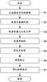
图8是表示视觉校正实习系统100的处理的流程图。FIG. 8 is a flowchart showing processing of the vision
在步骤S1中,虚拟空间生成部211生成虚拟空间V的图像。由虚拟空间生成部211生成的虚拟空间V显示于头戴式显示器1的显示面板14。In step S1, the virtual space generating unit 211 generates an image of the virtual space V. As shown in FIG. The virtual space V generated by the virtual space generating unit 211 is displayed on the
在步骤S2中,操作盘配置部212在虚拟空间V内配置机器人R的示教操作盘B。配置示教操作盘B的位置可以预先设定,也可以通过操作员的操作来设定。In step S2 , the operation
在步骤S3中,示教部213在虚拟空间V内配置机器人R以及工件W,以机器人R对工件W进行预定的动作的方式进行示教。In step S3 , the
在步骤S4中,照相机配置部214在虚拟空间V内,在工件W进入视野内的位置配置照相机C。In step S4 , the
在步骤S5中,坐标系设定部216在虚拟空间V内设定用于视觉校正的坐标系S,在虚拟空间V内配置坐标系S。坐标系确认部217确认由坐标系设定部216设定的坐标系S是为了进行视觉校正的适当位置。在坐标系S不是为了进行视觉校正的适当位置的情况下,通知部223在虚拟空间V内的其他窗口中显示表示坐标系S不是适当的位置的警报。In step S5 , the coordinate
在步骤S6中,视觉校正部221在工件W的位置移动后,基于由照相机C拍摄到的拍摄图像,对预定的动作进行视觉校正。In step S6 , the
在步骤S7中,校正确认部222确认对工件W适当地视觉校正了预定的动作。在未适当地进行视觉校正的情况下,通知部223在虚拟空间V内的其他窗口中显示表示未适当地进行视觉校正的警报。In step S7 , the
根据本实施方式,用于实习视觉校正的视觉校正实习系统100具备:头戴式显示器1,其能够显示虚拟空间的图像;以及示教装置2,其以能够通信的方式与头戴式显示器连接。示教装置2具有:虚拟空间生成部211,其生成虚拟空间的图像;示教部213,其在虚拟空间V内配置机器人R和工件W,以机器人R对工件W进行预定的动作的方式进行示教;照相机配置部214,其在虚拟空间V内,在工件W进入视野内的位置配置照相机C;视觉校正部221,其在工件W的位置移动之后,基于由照相机C拍摄到的摄像图像,对预定的动作进行视觉校正;以及校正确认部222,其确认预定的动作被适当地进行视觉校正。According to the present embodiment, the vision
通过使用这样的视觉校正实习系统100,操作员能够一边观察头戴式显示器1所显示的虚拟现实的影像一边实习视觉校正。因此,操作员能够提高对影像世界的沉浸感,能够高效地进行实习。By using such a vision
另外,视觉校正实习系统100还具备机器人的控制装置和示教操作盘,头戴式显示器1以能够通信的方式与控制装置连接,通过与控制装置连接的示教操作盘进行操作。In addition, the visual
另外,示教装置2还具备在虚拟空间V内配置机器人的示教操作盘B的操作盘配置部212。示教装置2还具备坐标系设定部216,其在虚拟空间内设定用于视觉校正的坐标系S,并在虚拟空间内配置坐标系S。另外,示教装置2还具备坐标系确认部217,其确认由坐标系设定部216设定的坐标系S是为了进行视觉校正的适当的位置。由此,操作员能够直观地理解坐标系S是为了进行视觉校正的适当的位置。因此,操作员能够高效地进行视觉校正的实习。In addition, the
另外,示教装置2还具备设定照相机C的光学条件的光学条件设定部215。由此,视觉校正实习系统100能够模拟照相机C的光学条件,因此操作员能够适当地设定照相机C的光学条件。In addition, the
另外,示教装置2还具备在虚拟空间V内显示警报的通知部223。由此,视觉校正实习系统100在没有适当地进行坐标系S和视觉校正的设定的情况下,能够通过所显示的警报对操作员进行通知。In addition, the
另外,示教装置2还具备:工件检测部218,其对工件W的模型图案进行示教,并使用模型图案从由照相机C拍摄工件W而得到的拍摄图像来检测工件W的位置;基准位置设定部219,其将由工件检测部218在拍摄图像中检测出工件W的位置设定为工件W的基准位置;以及计算部220,其在工件W的位置移动之后,计算由工件检测部218检测出的工件W的位置与基准位置的偏移量。然后,视觉校正部221使用计算出的偏移量,对预定的动作进行视觉校正。由此,视觉校正实习系统100能够使用计算出的偏移量适当地进行视觉校正。In addition, the
以上,对本发明的实施方式进行了说明,但本发明不限于所述的实施方式。另外,本实施方式所记载的效果只不过是列举了由本发明产生的最优选的效果,本发明的效果并不限定于本实施方式所记载的效果。As mentioned above, although embodiment of this invention was described, this invention is not limited to the said embodiment. In addition, the effects described in this embodiment are merely examples of the most preferable effects produced by the present invention, and the effects of the present invention are not limited to the effects described in this embodiment.
附图标记说明Explanation of reference signs
100视觉校正实习系统100 vision correction practice system
1头戴式显示器1 head mounted display
2示教装置2 teaching device
21控制部21 Control Department
22通信部22 Ministry of Communications
23存储部23 storage department
24操作部24 Operation Department
211虚拟空间生成部211 Virtual Space Creation Department
212操作盘配置部212 operation panel configuration department
213示教部213 Teaching Department
214照相机配置部214 Camera Configuration Department
215光学条件设定部215 Optical Condition Setting Department
216坐标系设定部216 Coordinate System Setting Department
217坐标系确认部217 Coordinate System Confirmation Department
218工件检测部218 Workpiece Inspection Department
219基准位置设定部219 Reference position setting unit
220计算部220 Computing Department
221视觉校正部221 Department of Vision Correction
222校正确认部222 Calibration Confirmation Department
223通知部。223 Notification to the Ministry.
Claims (8)
Translated fromChineseApplications Claiming Priority (3)
| Application Number | Priority Date | Filing Date | Title |
|---|---|---|---|
| JP2020-060313 | 2020-03-30 | ||
| JP2020060313 | 2020-03-30 | ||
| PCT/JP2021/012229WO2021200470A1 (en) | 2020-03-30 | 2021-03-24 | Off-line simulation system |
Publications (1)
| Publication Number | Publication Date |
|---|---|
| CN115397629Atrue CN115397629A (en) | 2022-11-25 |
Family
ID=77928366
Family Applications (1)
| Application Number | Title | Priority Date | Filing Date |
|---|---|---|---|
| CN202180025317.9APendingCN115397629A (en) | 2020-03-30 | 2021-03-24 | Off-line simulation system |
Country Status (5)
| Country | Link |
|---|---|
| US (1) | US12090669B2 (en) |
| JP (1) | JP7381718B2 (en) |
| CN (1) | CN115397629A (en) |
| DE (1) | DE112021002026B4 (en) |
| WO (1) | WO2021200470A1 (en) |
Citations (4)
| Publication number | Priority date | Publication date | Assignee | Title |
|---|---|---|---|---|
| CN101085523A (en)* | 2006-06-06 | 2007-12-12 | 发那科株式会社 | Robot simulation apparatus |
| CN102119072A (en)* | 2008-06-09 | 2011-07-06 | Abb技术有限公司 | A method and a system for facilitating calibration of an off-line programmed robot cell |
| CN110238831A (en)* | 2019-07-23 | 2019-09-17 | 青岛理工大学 | Robot teaching system and method based on RGB-D image and teaching device |
| CN110465951A (en)* | 2018-05-11 | 2019-11-19 | 西门子股份公司 | For the method for robotic programming, equipment, computer-readable storage medium and computer program |
Family Cites Families (11)
| Publication number | Priority date | Publication date | Assignee | Title |
|---|---|---|---|---|
| JP4266946B2 (en) | 2005-03-17 | 2009-05-27 | ファナック株式会社 | Offline teaching device |
| JP2009119589A (en) | 2007-11-19 | 2009-06-04 | Yaskawa Electric Corp | Robot simulator |
| JP5815761B2 (en)* | 2014-01-23 | 2015-11-17 | ファナック株式会社 | Visual sensor data creation system and detection simulation system |
| JP2015229234A (en)* | 2014-06-06 | 2015-12-21 | ナブテスコ株式会社 | Device and method for creating teaching data of working robot |
| JP6350037B2 (en)* | 2014-06-30 | 2018-07-04 | 株式会社安川電機 | Robot simulator and robot simulator file generation method |
| JP6126067B2 (en)* | 2014-11-28 | 2017-05-10 | ファナック株式会社 | Collaborative system with machine tool and robot |
| US9740191B2 (en)* | 2015-02-12 | 2017-08-22 | The Boeing Company | Location calibration for automated production manufacturing |
| JP7091609B2 (en)* | 2017-04-14 | 2022-06-28 | セイコーエプソン株式会社 | Simulation equipment, robot control equipment and robots |
| JP7259284B2 (en) | 2017-11-28 | 2023-04-18 | 株式会社デンソーウェーブ | Teaching device, teaching method |
| JP6693981B2 (en)* | 2018-02-19 | 2020-05-13 | ファナック株式会社 | Simulation device for simulating robot movement |
| JP6810093B2 (en) | 2018-04-25 | 2021-01-06 | ファナック株式会社 | Robot simulation device |
- 2021
- 2021-03-24CNCN202180025317.9Apatent/CN115397629A/enactivePending
- 2021-03-24DEDE112021002026.9Tpatent/DE112021002026B4/enactiveActive
- 2021-03-24JPJP2022512024Apatent/JP7381718B2/enactiveActive
- 2021-03-24USUS17/906,277patent/US12090669B2/enactiveActive
- 2021-03-24WOPCT/JP2021/012229patent/WO2021200470A1/ennot_activeCeased
Patent Citations (4)
| Publication number | Priority date | Publication date | Assignee | Title |
|---|---|---|---|---|
| CN101085523A (en)* | 2006-06-06 | 2007-12-12 | 发那科株式会社 | Robot simulation apparatus |
| CN102119072A (en)* | 2008-06-09 | 2011-07-06 | Abb技术有限公司 | A method and a system for facilitating calibration of an off-line programmed robot cell |
| CN110465951A (en)* | 2018-05-11 | 2019-11-19 | 西门子股份公司 | For the method for robotic programming, equipment, computer-readable storage medium and computer program |
| CN110238831A (en)* | 2019-07-23 | 2019-09-17 | 青岛理工大学 | Robot teaching system and method based on RGB-D image and teaching device |
Non-Patent Citations (1)
| Title |
|---|
| 丁国富,王金诺,吴晓著: "基于虚拟现实的物料搬运机械远程操作理论及仿真", 31 July 2007, 成都:西南交通大学出版社, pages: 53* |
Also Published As
| Publication number | Publication date |
|---|---|
| JPWO2021200470A1 (en) | 2021-10-07 |
| JP7381718B2 (en) | 2023-11-15 |
| WO2021200470A1 (en) | 2021-10-07 |
| US12090669B2 (en) | 2024-09-17 |
| US20230090193A1 (en) | 2023-03-23 |
| DE112021002026B4 (en) | 2025-07-10 |
| DE112021002026T5 (en) | 2023-02-09 |
Similar Documents
| Publication | Publication Date | Title |
|---|---|---|
| CN112578911B (en) | Apparatus and method for tracking head and eye movements | |
| US10818099B2 (en) | Image processing method, display device, and inspection system | |
| US9519736B2 (en) | Data generation device for vision sensor and detection simulation system | |
| US10139902B2 (en) | Method and apparatus for changing a field of view without synchronization with movement of a head-mounted display | |
| EP3644826A1 (en) | A wearable eye tracking system with slippage detection and correction | |
| JP6693981B2 (en) | Simulation device for simulating robot movement | |
| US20230130816A1 (en) | Calibration system, calibration method, and calibration apparatus | |
| JP7674464B2 (en) | Simulation device using 3D position information obtained from the output of a visual sensor | |
| KR20230065881A (en) | Robot teaching system | |
| JP2009269134A (en) | Simulation device in visual inspection apparatus | |
| JP2021026599A (en) | Image processing system | |
| JP7564327B2 (en) | Teaching Device | |
| EP3710774A1 (en) | Systems and methods for calibrating an eye tracking system | |
| CN115397629A (en) | Off-line simulation system | |
| CN115213894B (en) | Robot image display method, display system, and recording medium | |
| JPH1177568A (en) | Teaching assisting method and device | |
| CN114474010B (en) | An intuitive industrial robot simulation system | |
| TW202529973A (en) | Tool coordinate system setting device and setting method and robot system | |
| WO2025158559A1 (en) | Tool coordinate system setting device, setting method, and robot system | |
| JP2024035544A (en) | Information processing device, information processing method, program | |
| CN117532584A (en) | Mechanical arm teaching method, device, equipment and storage medium |
Legal Events
| Date | Code | Title | Description |
|---|---|---|---|
| PB01 | Publication | ||
| PB01 | Publication | ||
| SE01 | Entry into force of request for substantive examination | ||
| SE01 | Entry into force of request for substantive examination |