CN115397166A - Bottom blocking plate of new communication cabinet free of punching - Google Patents
Bottom blocking plate of new communication cabinet free of punchingDownload PDFInfo
- Publication number
- CN115397166A CN115397166ACN202211241070.7ACN202211241070ACN115397166ACN 115397166 ACN115397166 ACN 115397166ACN 202211241070 ACN202211241070 ACN 202211241070ACN 115397166 ACN115397166 ACN 115397166A
- Authority
- CN
- China
- Prior art keywords
- communication
- communication cabinet
- plugging
- wiring hole
- main body
- Prior art date
- Legal status (The legal status is an assumption and is not a legal conclusion. Google has not performed a legal analysis and makes no representation as to the accuracy of the status listed.)
- Pending
Links
Images


Classifications
- H—ELECTRICITY
- H05—ELECTRIC TECHNIQUES NOT OTHERWISE PROVIDED FOR
- H05K—PRINTED CIRCUITS; CASINGS OR CONSTRUCTIONAL DETAILS OF ELECTRIC APPARATUS; MANUFACTURE OF ASSEMBLAGES OF ELECTRICAL COMPONENTS
- H05K5/00—Casings, cabinets or drawers for electric apparatus
- H05K5/02—Details
- H05K5/0247—Electrical details of casings, e.g. terminals, passages for cables or wiring
- H—ELECTRICITY
- H05—ELECTRIC TECHNIQUES NOT OTHERWISE PROVIDED FOR
- H05K—PRINTED CIRCUITS; CASINGS OR CONSTRUCTIONAL DETAILS OF ELECTRIC APPARATUS; MANUFACTURE OF ASSEMBLAGES OF ELECTRICAL COMPONENTS
- H05K5/00—Casings, cabinets or drawers for electric apparatus
- H05K5/06—Hermetically-sealed casings
- H05K5/069—Other details of the casing, e.g. wall structure, passage for a connector, a cable, a shaft
- H—ELECTRICITY
- H05—ELECTRIC TECHNIQUES NOT OTHERWISE PROVIDED FOR
- H05K—PRINTED CIRCUITS; CASINGS OR CONSTRUCTIONAL DETAILS OF ELECTRIC APPARATUS; MANUFACTURE OF ASSEMBLAGES OF ELECTRICAL COMPONENTS
- H05K7/00—Constructional details common to different types of electric apparatus
- H05K7/14—Mounting supporting structure in casing or on frame or rack
- H05K7/1401—Mounting supporting structure in casing or on frame or rack comprising clamping or extracting means
Landscapes
- Engineering & Computer Science (AREA)
- Microelectronics & Electronic Packaging (AREA)
- Casings For Electric Apparatus (AREA)
Abstract
Description
Translated fromChinese技术领域technical field
本发明涉及通信柜封堵板技术领域,具体为免打孔新型通信机柜底部封堵板。The invention relates to the technical field of communication cabinet sealing boards, in particular to a new type of communication cabinet bottom sealing board without punching holes.
背景技术Background technique
目前,通信机柜下走线方式一般是安装在防静电地板或者槽钢支架上,机柜底部的防静电地板或封堵板预留给线缆走线的孔在安装前预先切割好,安装时候将线缆穿过孔来布线。At present, the cable routing method under the communication cabinet is generally installed on the anti-static floor or channel steel bracket. The anti-static floor or blocking plate at the bottom of the cabinet is reserved for cable routing. The cables are routed through the holes.
如果防静电地板或封堵板的孔径预留过小,以后需要增加线缆时就难以甚至无法穿线缆,由于机柜已固定及有在运行线缆,也无法再扩大线缆孔;如果孔径预留过大,则封堵时需要大量的防火泥,且无东西支撑防火泥将不牢固,容易掉落,达不到孔洞封堵的要求,需要增加线缆时要移开防火泥穿好线缆后再封堵回去,费时费力也不美观。If the hole diameter of the anti-static floor or the blocking board is too small, it will be difficult or even impossible to pass the cable when it is necessary to add cables in the future. Since the cabinet is fixed and there are running cables, the cable hole cannot be enlarged; if the hole diameter If the reserve is too large, a large amount of fireproof mud will be needed for sealing, and the fireproof mud will not be firm if there is no support, and it will fall easily, which will not meet the requirements for hole sealing. When it is necessary to add cables, remove the fireproof mud and wear them well. After the cable is plugged back, it is time-consuming, laborious and unsightly.
因此针对上述问题,我们提出免打孔新型通信机柜底部封堵板。Therefore, in response to the above problems, we propose a new type of blocking plate at the bottom of the communication cabinet without punching holes.
发明内容Contents of the invention
(一)解决的技术问题(1) Solved technical problems
针对现有技术的不足,本发明提供了免打孔新型通信机柜底部封堵板,具备可根据通信走线孔内部通信线缆数量调整通信走线孔的通孔直径大小,从而提高通信柜在后续增加线缆时的方便程度,同时也防止通信走线孔过大导致需要大量防火泥堵塞通信走线孔的现象,降低浪费,减少成本的优点,解决了现有防静电地板或封堵板的孔径预留过小,以后需要增加线缆时就难以甚至无法穿线缆,由于机柜已固定及有在运行线缆,也无法再扩大线缆孔;如果孔径预留过大,则封堵时需要大量的防火泥,且无东西支撑防火泥将不牢固,容易掉落,达不到孔洞封堵的要求,需要增加线缆时要移开防火泥穿好线缆后再封堵回去,费时费力也不美观的问题。Aiming at the deficiencies of the prior art, the present invention provides a new type of communication cabinet bottom blocking plate without punching holes, which can adjust the diameter of the through hole of the communication wiring hole according to the number of communication cables inside the communication wiring hole, thereby improving the communication cabinet. The convenience of adding cables in the future, and at the same time prevent the phenomenon that the communication wiring holes are too large to block the communication wiring holes due to the need for a large amount of fireproof mud, reduce waste and reduce costs, and solve the problem of existing anti-static floor or blocking board If the reserved hole diameter is too small, it will be difficult or even impossible to pass cables when additional cables are needed in the future. Since the cabinet is fixed and there are running cables, the cable hole cannot be expanded; if the hole diameter is too large, it will be blocked. A large amount of fireproof mud is needed, and if there is no support, the fireproof mud will be unstable and easy to fall, which cannot meet the requirements for hole sealing. When it is necessary to add cables, remove the fireproof mud and put on the cables before sealing them back. A time-consuming and labor-intensive problem that is not beautiful.
(二)技术方案(2) Technical solutions
为实现上述目的,本发明提供如下技术方案:免打孔新型通信机柜底部封堵板,包括封堵板主体、通信柜主体和新型封堵材料,所述通信柜主体位于封堵板主体上表面,所述封堵板主体内部开设有通信走线孔,所述通信走线孔内部设置有走线孔封堵装置,所述走线孔封堵装置包括封堵块,两组所述封堵块相互远离的一端固定安装有连接板,所述连接板上下侧壁固定安装有限位块,所述连接板远离封堵块的一端固定安装有第一滑杆,所述第一滑杆远离连接板的一端滑动连接有第二滑杆,所述第一滑杆上套设有第一复位弹簧。In order to achieve the above object, the present invention provides the following technical solution: a new type of plugging plate at the bottom of the communication cabinet without punching, including a main body of the blocking plate, a main body of the communication cabinet and a new type of blocking material, and the main body of the communication cabinet is located on the upper surface of the main body of the blocking plate , the inside of the main body of the blocking board is provided with a communication wiring hole, and a wiring hole blocking device is arranged inside the communication wiring hole, and the wiring hole blocking device includes a blocking block, and the two groups of the blocking A connecting plate is fixedly installed on the ends of the blocks far away from each other, and a limit block is fixedly installed on the upper and lower side walls of the connecting plate, and a first slide bar is fixedly installed on the end of the connecting plate away from the blocking block. One end of the plate is slidably connected with a second slide bar, and the first return spring is sheathed on the first slide bar.
优选的,所述封堵块的大小与通信走线孔相适配,两组所述封堵块相互靠近的一端安装有半圆形橡胶垫,两组封堵块可对通信走线孔内部线缆进行夹持固定的同时,方便新型封堵材料的放入。Preferably, the size of the blocking block is adapted to the communication routing hole, and semicircular rubber pads are installed at the ends of the two groups of blocking blocks that are close to each other. While clamping and fixing, it is convenient to put in the new plugging material.
优选的,所述连接板的大小与通信走线孔相适配,所述通信走线孔内部开设有与限位块相适配的限位槽,所述封堵板主体内部位于通信走线孔的两侧开设有与连接板相适配的连接槽,所述连接板和限位块通过通信走线孔与封堵板主体滑动连接,限位块起到防止连接板在通信走线孔内部左右滑动时的脱轨现象。Preferably, the size of the connecting plate is adapted to the communication wiring hole, and a limit slot matching the limit block is opened inside the communication wiring hole, and the inside of the main body of the blocking plate is located in the communication wiring hole. There are connecting grooves on both sides that are compatible with the connecting plate. The connecting plate and the limiting block are slidingly connected to the main body of the blocking plate through the communication wiring hole. Derailment during sliding.
优选的,所述第二滑杆远离第一滑杆的一端与封堵板主体固定连接,所述第二滑杆的内径尺寸与第一滑杆的外径尺寸相匹配,所述第一复位弹簧的两端分别与第二滑杆和连接板固定连接,第一复位弹簧起到两组封堵块自动靠拢,从而夹持通信走线孔内部线缆的作用。Preferably, the end of the second sliding rod away from the first sliding rod is fixedly connected to the main body of the blocking plate, the inner diameter of the second sliding rod matches the outer diameter of the first sliding rod, and the first reset The two ends of the spring are respectively fixedly connected with the second sliding rod and the connection plate, and the first return spring plays the role of automatically closing the two sets of blocking blocks, thereby clamping the internal cables of the communication wiring hole.
优选的,所述通信柜主体内部固定安装有支撑条,两组所述支撑条之间安装有滑块,两组所述滑块之间固定安装有置放板,所述滑块靠近支撑条的一侧开设有与支撑条相适配的滑槽,所述滑块通过滑槽与支撑条滑动连接,所述支撑条内部开设有上下等距分布的插孔,滑块可通过滑槽在支撑条表面上下滑动,从而调整置放板之间的间距大小,提高对通信柜主体内部的空间利用率。Preferably, a support bar is fixedly installed inside the main body of the communication cabinet, a slider is installed between two groups of the support bars, a placement plate is fixedly installed between the two groups of the sliders, and the slider is close to the support bar One side of the support bar is provided with a chute that is compatible with the support bar. The slider is slidably connected with the support bar through the chute. The inside of the support bar is provided with jacks that are equidistant from top to bottom. The slider can pass through the chute in the The surface of the support bar slides up and down, so as to adjust the distance between the placement boards and improve the space utilization rate inside the main body of the communication cabinet.
优选的,所述滑块内部设置有锁紧结构,所述锁紧结构与滑槽为轴向分布,所述锁紧结构包括固定环,所述固定环内部滑动连接有插杆,所述插杆贯通滑块,所述插杆靠近滑槽的一端固定安装有限位环,所述限位环与固定环之间固定安装有第二复位弹簧,且第二复位弹簧套设在插杆上,所述插杆远离限位环的一端固定安装有拉环,所述插杆的外径尺寸与插孔的内径尺寸相匹配,插杆可在固定环内部左右滑动,从而配合插孔固定滑块在支撑条上的高度,而第二复位弹簧起到插杆与插孔在无外力情况下的自动插接作用。Preferably, a locking structure is provided inside the slider, and the locking structure and the chute are axially distributed. The locking structure includes a fixed ring, and an insertion rod is slidably connected to the inside of the fixed ring. The rod passes through the slider, and the end of the insertion rod close to the chute is fixedly installed with a limit ring, and a second return spring is fixedly installed between the limit ring and the fixed ring, and the second return spring is sleeved on the insertion rod. The end of the insertion rod away from the limit ring is fixedly equipped with a pull ring, the outer diameter of the insertion rod matches the inner diameter of the socket, and the insertion rod can slide left and right inside the fixed ring, thereby fixing the slider with the socket The height above the support bar, and the second return spring plays the role of automatic insertion between the insertion rod and the jack under the condition of no external force.
优选的,所述通信柜主体底部固定安装有支脚,所述支脚呈“L”形,所述支脚内部开设有固定孔,所述通信柜主体通过支脚与封堵板主体固定连接,支脚起到通信柜主体与封堵板主体的固定作用。Preferably, the bottom of the main body of the communication cabinet is fixedly equipped with a leg, the leg is in the shape of an "L", and a fixing hole is provided inside the leg, the main body of the communication cabinet is fixedly connected with the main body of the blocking plate through the leg, and the leg acts as a The fixing function of the main body of the communication cabinet and the main body of the blocking plate.
优选的,所述通信柜主体侧壁铰接有柜门,所述封堵板主体底部四角处固定安装有支撑脚,支撑脚起到该装置整体的支撑结构作用,使封堵板主体与地面保持一定高度。Preferably, the side wall of the main body of the communication cabinet is hinged with a cabinet door, and the four corners of the bottom of the main body of the blocking plate are fixedly equipped with supporting feet, and the supporting feet play the role of the overall supporting structure of the device, so that the main body of the blocking plate is kept in contact with the ground. a certain height.
本发明还提出新型封堵材料的制备工艺,包括以下具体步骤:The present invention also proposes a preparation process for a novel plugging material, which includes the following specific steps:
步骤一:将重质沥青或热塑性树脂经过热处理后得到炭质中间相,并采用硫酸和浓硝酸的混合溶液对炭质中间相进行硝化处理,且硝化反应的温度保持在0-100摄氏度,即可得到炭质的硝化中间相;Step 1: heat-treat heavy asphalt or thermoplastic resin to obtain a carbonaceous mesophase, and use a mixed solution of sulfuric acid and concentrated nitric acid to nitrate the carbonaceous mesophase, and keep the temperature of the nitration reaction at 0-100 degrees Celsius, that is Carbonaceous nitrification mesophase can be obtained;
步骤二:由于步骤一所制备的硝化炭质中间相具有水溶性基团,因此当硝化炭质中间相其ph值小于2时,可得到泥状析出物,因此可在硝化炭质中间相中加入硫酸或硝酸和去离子水以调节硝化炭质中间相溶液的ph值小于2,即可得到泥状析出物;Step 2: Since the nitrified carbonaceous mesophase prepared in
步骤三:将步骤二所制备的泥状析出物经过过滤并干燥成粒状物,即可得到水溶性炭质中间相,并将所得到的水溶性炭质中间相进过300摄氏度高温处理,使其膨胀发泡,然后经过2400摄氏度高温石墨化处理后,即可得到弹性石墨封堵材料。Step 3: Filter and dry the muddy precipitate prepared in
其中新型封堵材料为弹性石墨封堵材料。Among them, the new plugging material is elastic graphite plugging material.
(三)有益效果(3) Beneficial effects
与现有技术相比,本发明提供了免打孔新型通信机柜底部封堵板,具备以下有益效果:Compared with the prior art, the present invention provides a new type of blocking plate at the bottom of the communication cabinet without punching holes, which has the following beneficial effects:
1、该装置通过在免打孔新型通信机柜底部封堵板上设计由封堵块、连接板、限位块、第一滑杆、第二滑杆和第一复位弹簧所构成的走线孔封堵装置,可根据通信走线孔内部通信线缆数量调整通信走线孔的通孔直径大小,从而提高通信柜在后续增加线缆时的方便程度,同时也防止通信走线孔过大导致需要大量防火泥堵塞通信走线孔的现象,降低浪费,减少成本。1. The device designs a wiring hole consisting of a blocking block, a connecting plate, a limit block, a first sliding rod, a second sliding rod and a first return spring on the blocking plate at the bottom of the new communication cabinet without punching holes. The blocking device can adjust the diameter of the communication wiring hole according to the number of communication cables inside the communication wiring hole, so as to improve the convenience of the communication cabinet when adding cables in the future, and also prevent the communication wiring hole from being too large. A large amount of fireproof mud is required to block the communication wiring hole, reducing waste and cost.
2、该装置通过在免打孔新型通信机柜底部封堵板上设计由固定环、插杆、限位环、第二复位弹簧和拉环所构成的锁紧结构,可配合滑块、滑槽和支撑条上下滑动置放板,从而根据置放板上零器件大小调整置放板之间的间距大小,从而提高通信柜主体内部空间的利用率。2. The device designs a locking structure consisting of a fixed ring, an insertion rod, a limit ring, a second return spring and a pull ring on the bottom blocking plate of a new type of communication cabinet without punching holes, and can cooperate with sliders and chute Slide the placement board up and down with the support bar, thereby adjusting the spacing between the placement boards according to the size of the zero components on the placement board, thereby improving the utilization rate of the internal space of the communication cabinet main body.
3、该装置通过在免打孔新型通信机柜底部封堵板上通信走线孔内部设计新型封堵材料,该新型封堵材料为弹性石墨封堵材料,此材料具有一定的弹性和收缩性,软硬适中,具有防火防小动物功能,在未穿线缆时处于完全封堵状态,在增加线缆时只要将封堵材料拉开就可随意进行穿线,穿线后将封堵材料拉回包裹线缆,从而达到封堵目的,无需防火泥封堵。3. The device designs a new type of plugging material inside the communication wiring hole on the bottom plugging board of the new communication cabinet without punching holes. The new type of plugging material is an elastic graphite plugging material, which has certain elasticity and shrinkage. It is moderately soft and hard, and has the function of fire prevention and small animals. It is in a completely blocked state when the cable is not threaded. When adding cables, you only need to pull the plugging material away to thread it freely. After threading, pull the plugging material back into the package. Cables, so as to achieve the purpose of blocking, without fireproof mud plugging.
附图说明Description of drawings
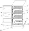
图1为本发明整体结构示意图;Fig. 1 is a schematic diagram of the overall structure of the present invention;
图2为本发明通信走线孔内部结构示意图;Fig. 2 is a schematic diagram of the internal structure of the communication wiring hole of the present invention;
图3为本发明走线孔封堵装置结构示意图;Fig. 3 is a structural schematic diagram of the wiring hole plugging device of the present invention;
图4为本发明置放板、滑块及锁紧结构示意图;Fig. 4 is a schematic diagram of the placement plate, slider and locking structure of the present invention;
图5为本发明锁紧结构示意图。Fig. 5 is a schematic diagram of the locking structure of the present invention.
图中:1、封堵板主体;2、通信柜主体;3、通信走线孔;4、走线孔封堵装置;401、封堵块;402、连接板;403、限位块;404、第一滑杆;405、第二滑杆;406、第一复位弹簧;5、支撑条;6、滑块;7、置放板;8、锁紧结构;801、固定环;802、插杆;803、限位环;804、第二复位弹簧;805、拉环;9、插孔;10、支脚;11、柜门;12、支撑脚;13、滑槽。In the figure: 1. The main body of the blocking plate; 2. The main body of the communication cabinet; 3. The communication wiring hole; 4. The wiring hole sealing device; 401, the blocking block; 402, the connection plate; 403, the limit block; 404 , the first slide bar; 405, the second slide bar; 406, the first return spring; 5, the support bar; 6, the slider; 7, the placement plate; 8, the locking structure; Rod; 803, limit ring; 804, second back-moving spring; 805, pull ring; 9, jack; 10, supporting foot; 11, cabinet door; 12, supporting foot;
具体实施方式Detailed ways
下面将结合本发明实施例中的附图,对本发明实施例中的技术方案进行清楚、完整地描述,显然,所描述的实施例仅仅是本发明一部分实施例,而不是全部的实施例。基于本发明中的实施例,本领域普通技术人员在没有做出创造性劳动前提下所获得的所有其他实施例,都属于本发明保护的范围。The following will clearly and completely describe the technical solutions in the embodiments of the present invention with reference to the accompanying drawings in the embodiments of the present invention. Obviously, the described embodiments are only some, not all, embodiments of the present invention. Based on the embodiments of the present invention, all other embodiments obtained by persons of ordinary skill in the art without making creative efforts belong to the protection scope of the present invention.
实施例一:Embodiment one:
请参阅图1-5,免打孔新型通信机柜底部封堵板,包括封堵板主体1、通信柜主体2和新型封堵材料,通信柜主体2位于封堵板主体1上表面,封堵板主体1内部开设有通信走线孔3,通信走线孔3内部设置有走线孔封堵装置 4,走线孔封堵装置4包括封堵块401,两组封堵块401相互远离的一端固定安装有连接板402,连接板402上下侧壁固定安装有限位块403,连接板402 远离封堵块401的一端固定安装有第一滑杆404,第一滑杆404远离连接板402的一端滑动连接有第二滑杆405,第一滑杆404上套设有第一复位弹簧 406。Please refer to Figure 1-5, the bottom sealing plate of the new communication cabinet without punching, including the
请参阅图3,封堵块401的大小与通信走线孔3相适配,两组封堵块401 相互靠近的一端安装有半圆形橡胶垫,两组封堵块401可对通信走线孔3内部线缆进行夹持固定的同时,方便新型封堵材料的放入;连接板402的大小与通信走线孔3相适配,通信走线孔3内部开设有与限位块403相适配的限位槽,封堵板主体1内部位于通信走线孔3的两侧开设有与连接板402相适配的连接槽,连接板402和限位块403通过通信走线孔3与封堵板主体1滑动连接,限位块403起到防止连接板402在通信走线孔3内部左右滑动时的脱轨现象;第二滑杆405远离第一滑杆404的一端与封堵板主体1固定连接,第二滑杆405的内径尺寸与第一滑杆404的外径尺寸相匹配,第一复位弹簧 406的两端分别与第二滑杆405和连接板402固定连接,第一复位弹簧406 起到两组封堵块401自动靠拢,从而夹持通信走线孔3内部线缆的作用。Please refer to Figure 3, the size of the blocking
实施例二:Embodiment two:
请参与图1,在实施例一的基础上,通信柜主体2内部固定安装有支撑条 5,两组支撑条5之间安装有滑块6,两组滑块6之间固定安装有置放板7,滑块6靠近支撑条5的一侧开设有与支撑条5相适配的滑槽13,滑块6通过滑槽13与支撑条5滑动连接,支撑条5内部开设有上下等距分布的插孔9,滑块6可通过滑槽13在支撑条5表面上下滑动,从而调整置放板7之间的间距大小,提高对通信柜主体2内部的空间利用率;通信柜主体2底部固定安装有支脚10,支脚10呈“L”形,支脚10内部开设有固定孔,通信柜主体2 通过支脚10与封堵板主体1固定连接,支脚10起到通信柜主体2与封堵板主体1的固定作用;通信柜主体2侧壁铰接有柜门11,封堵板主体1底部四角处固定安装有支撑脚12,支撑脚12起到该装置整体的支撑结构作用,使封堵板主体1与地面保持一定高度。Please refer to Figure 1. On the basis of
请参阅图5,滑块6内部设置有锁紧结构8,锁紧结构8与滑槽13为轴向分布,锁紧结构8包括固定环801,固定环801内部滑动连接有插杆802,插杆802贯通滑块6,插杆802靠近滑槽13的一端固定安装有限位环803,限位环803与固定环801之间固定安装有第二复位弹簧804,且第二复位弹簧 804套设在插杆802上,插杆802远离限位环803的一端固定安装有拉环805,插杆802的外径尺寸与插孔9的内径尺寸相匹配,插杆802可在固定环801 内部左右滑动,从而配合插孔9固定滑块6在支撑条5上的高度,而第二复位弹簧804起到插杆802与插孔9在无外力情况下的自动插接作用。Please refer to Fig. 5, a locking structure 8 is arranged inside the
工作原理:使用时,首先将新型封堵材料放置在两组封堵块401之间,之后将通信柜主体2所需线缆穿过通信走线孔3,即两组封堵块401之间的新型封堵材料内部,因新型封堵材料为弹性石墨封堵材料其具有一定的弹性和收缩性,软硬适中,在未穿线缆时处于完全封堵状态,在增加线缆时只要将封堵材料拉开就可随意进行穿线,穿线后将封堵材料拉回包裹线缆,即可达到封堵目的,当通信柜主体2内部需要增加线缆时,此时工作人员可手动滑动连接板402,使连接板402带动两组封堵块401向相互远离的方向运动,从而扩大通信走线孔3内部的孔径大小,方便更多线缆的穿入,当线缆穿入结束后,工作人员可松开对连接板402的外力,连接板402在第一复位弹簧406 的压力下,带动封堵块401相互靠拢,直至第一复位弹簧406的弹性势能抵消,即可实现线缆的固定与通信走线孔3的封堵作用,而当需要调整两组置放板7之间间距大小时,工作人员可对拉环805施加一定的外力,使插杆802与插孔9分离,此时工作人员可通过滑槽13带动滑块6在支撑条5侧壁上下移动,当置放板7之间间距调整完成后,即可松开对拉环805的外力,插杆 802在第二复位弹簧804的外力下重新插接进插孔9内部,进而固定置放板7 和滑块6的高度。Working principle: When in use, first place the new blocking material between the two sets of blocking
综上所述,本发明所提出的免打孔新型通信机柜底部封堵板,具备可根据通信走线孔内部通信线缆数量调整通信走线孔的通孔直径大小,从而提高通信柜在后续增加线缆时的方便程度,同时也防止通信走线孔过大导致需要大量防火泥堵塞通信走线孔的现象,降低浪费,减少成本的优点。To sum up, the bottom blocking plate of the new communication cabinet without punching proposed by the present invention has the ability to adjust the diameter of the through hole of the communication wiring hole according to the number of communication cables inside the communication wiring hole, thereby improving the communication cabinet in the follow-up. It increases the convenience of cables, and at the same time prevents the communication wiring holes from being too large, resulting in the need for a large amount of fireproof mud to block the communication wiring holes, reducing waste and reducing costs.
需要说明的是,在本文中,诸如第一和第二等之类的关系术语仅仅用来将一个实体或者操作与另一个实体或操作区分开来,而不一定要求或者暗示这些实体或操作之间存在任何这种实际的关系或者顺序。而且,术语“包括”、“包含”或者其任何其他变体意在涵盖非排他性的包含,从而使得包括一系列要素的过程、方法、物品或者设备不仅包括那些要素,而且还包括没有明确列出的其他要素,或者是还包括为这种过程、方法、物品或者设备所固有的要素。在没有更多限制的情况下,由语句“包括一个……”限定的要素,并不排除在包括所述要素的过程、方法、物品或者设备中还存在另外的相同要素。It should be noted that in this article, relational terms such as first and second are only used to distinguish one entity or operation from another entity or operation, and do not necessarily require or imply that there is a relationship between these entities or operations. There is no such actual relationship or order between them. Furthermore, the term "comprises", "comprises" or any other variation thereof is intended to cover a non-exclusive inclusion such that a process, method, article or apparatus comprising a set of elements includes not only those elements, but also includes elements not expressly listed. other elements of or also include elements inherent in such a process, method, article, or device. Without further limitations, an element defined by the phrase "comprising a ..." does not exclude the presence of additional identical elements in the process, method, article or apparatus comprising said element.
尽管已经示出和描述了本发明的实施例,对于本领域的普通技术人员而言,可以理解在不脱离本发明的原理和精神的情况下可以对这些实施例进行多种变化、修改、替换和变型,本发明的范围由所附权利要求及其等同物限定。Although the embodiments of the present invention have been shown and described, those skilled in the art can understand that various changes, modifications and substitutions can be made to these embodiments without departing from the principle and spirit of the present invention. and modifications, the scope of the invention is defined by the appended claims and their equivalents.
Claims (9)
Priority Applications (1)
| Application Number | Priority Date | Filing Date | Title |
|---|---|---|---|
| CN202211241070.7ACN115397166A (en) | 2022-10-11 | 2022-10-11 | Bottom blocking plate of new communication cabinet free of punching |
Applications Claiming Priority (1)
| Application Number | Priority Date | Filing Date | Title |
|---|---|---|---|
| CN202211241070.7ACN115397166A (en) | 2022-10-11 | 2022-10-11 | Bottom blocking plate of new communication cabinet free of punching |
Publications (1)
| Publication Number | Publication Date |
|---|---|
| CN115397166Atrue CN115397166A (en) | 2022-11-25 |
Family
ID=84128225
Family Applications (1)
| Application Number | Title | Priority Date | Filing Date |
|---|---|---|---|
| CN202211241070.7APendingCN115397166A (en) | 2022-10-11 | 2022-10-11 | Bottom blocking plate of new communication cabinet free of punching |
Country Status (1)
| Country | Link |
|---|---|
| CN (1) | CN115397166A (en) |
Citations (13)
| Publication number | Priority date | Publication date | Assignee | Title |
|---|---|---|---|---|
| US20030188883A1 (en)* | 2001-03-22 | 2003-10-09 | Kazuyoshi Yano | Electronic device and information reproducing system |
| CN105524600A (en)* | 2016-02-24 | 2016-04-27 | 中石化重庆涪陵页岩气勘探开发有限公司 | Plugging while drilling agent for oil-based drilling fluid and preparation method of plugging while drilling agent |
| CN207896439U (en)* | 2017-12-29 | 2018-09-21 | 天津鑫正天电力投资发展有限公司 | A kind of ring main unit of bottom plate plug-in type |
| CN210579607U (en)* | 2019-06-06 | 2020-05-19 | 国网山东省电力公司嘉祥县供电公司 | A communication cabinet blocking plate and a communication cabinet using the same |
| CN212542972U (en)* | 2020-07-15 | 2021-02-12 | 河南万控电气设备有限公司 | Wire-passing sealing structure of distribution box |
| CN212676662U (en)* | 2020-07-29 | 2021-03-09 | 广州沃亚电气设备有限公司 | Novel dampproofing shutoff regulator cubicle |
| CN212849806U (en)* | 2020-07-08 | 2021-03-30 | 西安昱瑞电力科技有限公司 | Dampproofing condensation plugging device that prevents of cubical switchboard |
| CN213818527U (en)* | 2020-12-29 | 2021-07-27 | 固安广通铁路电务器材有限公司 | Regionalized multi-reserved-aperture communication cabinet |
| CN215119638U (en)* | 2021-05-26 | 2021-12-10 | 中国能源建设集团甘肃省电力设计院有限公司 | Fireproof mud plugging device for electrical control cabinet of transformer substation |
| CN215156956U (en)* | 2021-05-17 | 2021-12-14 | 青岛增刚机械有限公司 | Adjustable axle type part strorage device |
| CN215582033U (en)* | 2021-05-24 | 2022-01-18 | 南昌交通学院 | Control cabinet based on PLC automatic control |
| CN113943486A (en)* | 2021-10-26 | 2022-01-18 | 杭州博源电力设备有限公司 | Cable plugging material and preparation method thereof |
| CN217063224U (en)* | 2022-03-28 | 2022-07-26 | 郑州市蓝清科技有限公司 | Cable pit fire prevention plugging device |
- 2022
- 2022-10-11CNCN202211241070.7Apatent/CN115397166A/enactivePending
Patent Citations (13)
| Publication number | Priority date | Publication date | Assignee | Title |
|---|---|---|---|---|
| US20030188883A1 (en)* | 2001-03-22 | 2003-10-09 | Kazuyoshi Yano | Electronic device and information reproducing system |
| CN105524600A (en)* | 2016-02-24 | 2016-04-27 | 中石化重庆涪陵页岩气勘探开发有限公司 | Plugging while drilling agent for oil-based drilling fluid and preparation method of plugging while drilling agent |
| CN207896439U (en)* | 2017-12-29 | 2018-09-21 | 天津鑫正天电力投资发展有限公司 | A kind of ring main unit of bottom plate plug-in type |
| CN210579607U (en)* | 2019-06-06 | 2020-05-19 | 国网山东省电力公司嘉祥县供电公司 | A communication cabinet blocking plate and a communication cabinet using the same |
| CN212849806U (en)* | 2020-07-08 | 2021-03-30 | 西安昱瑞电力科技有限公司 | Dampproofing condensation plugging device that prevents of cubical switchboard |
| CN212542972U (en)* | 2020-07-15 | 2021-02-12 | 河南万控电气设备有限公司 | Wire-passing sealing structure of distribution box |
| CN212676662U (en)* | 2020-07-29 | 2021-03-09 | 广州沃亚电气设备有限公司 | Novel dampproofing shutoff regulator cubicle |
| CN213818527U (en)* | 2020-12-29 | 2021-07-27 | 固安广通铁路电务器材有限公司 | Regionalized multi-reserved-aperture communication cabinet |
| CN215156956U (en)* | 2021-05-17 | 2021-12-14 | 青岛增刚机械有限公司 | Adjustable axle type part strorage device |
| CN215582033U (en)* | 2021-05-24 | 2022-01-18 | 南昌交通学院 | Control cabinet based on PLC automatic control |
| CN215119638U (en)* | 2021-05-26 | 2021-12-10 | 中国能源建设集团甘肃省电力设计院有限公司 | Fireproof mud plugging device for electrical control cabinet of transformer substation |
| CN113943486A (en)* | 2021-10-26 | 2022-01-18 | 杭州博源电力设备有限公司 | Cable plugging material and preparation method thereof |
| CN217063224U (en)* | 2022-03-28 | 2022-07-26 | 郑州市蓝清科技有限公司 | Cable pit fire prevention plugging device |
Non-Patent Citations (1)
| Title |
|---|
| 苏和;陆剑云;蒋树风;许弋;尹锦泉;: "高压柜内干空气正压交换及露点检测控制系统研制", 科技创新与应用, no. 36, 28 December 2015 (2015-12-28)* |
Similar Documents
| Publication | Publication Date | Title |
|---|---|---|
| CN206825017U (en) | A kind of perforating device for building of convenient use | |
| CN115397166A (en) | Bottom blocking plate of new communication cabinet free of punching | |
| CN210926904U (en) | A cable head making and fixing device | |
| CN205347626U (en) | Polysilicon ingot furnace | |
| CN209245477U (en) | Hydraulic engineering drainage pipeline fixed frame | |
| CN218301558U (en) | A distribution frame for building intelligent engineering | |
| CN207340377U (en) | Pallet and cabinet | |
| CN207338469U (en) | One kind just puts formula battery case | |
| CN202753333U (en) | Safety stripper mechanism for foaming of door bodies | |
| CN205286897U (en) | Mud therapy machine based on mud therapy is recovered to be used | |
| CN110360394B (en) | Snap-on Fire Rigid Clamp | |
| CN208394501U (en) | Convenient for the cable transmission of coiling | |
| CN221978545U (en) | Cable bridge device for computer room | |
| CN218292515U (en) | Parapet protective structure of slope roof | |
| CN207669693U (en) | A kind of mold locating ring convenient for adjusting | |
| CN223268706U (en) | Material rack structure for heat treatment of nanocrystalline magnetic core | |
| CN216542904U (en) | A pipeline lifting component for water supply and drainage design | |
| CN217129144U (en) | Mounting structure of ground surface protection network | |
| CN218375702U (en) | Safety protection structure of water conservancy construction | |
| CN220664032U (en) | Pipe blocking device structure | |
| CN218670893U (en) | Recoverable free movement draw-in groove formula pipeline bracket | |
| CN213391216U (en) | Stair template for construction | |
| CN222665115U (en) | Telescopic hanging beam | |
| CN215519304U (en) | Fire-proof base device | |
| CN218102213U (en) | Block terminal for photovoltaic microgrid easy to assemble |
Legal Events
| Date | Code | Title | Description |
|---|---|---|---|
| PB01 | Publication | ||
| PB01 | Publication | ||
| SE01 | Entry into force of request for substantive examination | ||
| SE01 | Entry into force of request for substantive examination | ||
| AD01 | Patent right deemed abandoned | ||
| AD01 | Patent right deemed abandoned | Effective date of abandoning:20250725 |