CN115381549A - A microcatheter for radiofrequency ablation with adjustable curvature - Google Patents
A microcatheter for radiofrequency ablation with adjustable curvatureDownload PDFInfo
- Publication number
- CN115381549A CN115381549ACN202210917984.4ACN202210917984ACN115381549ACN 115381549 ACN115381549 ACN 115381549ACN 202210917984 ACN202210917984 ACN 202210917984ACN 115381549 ACN115381549 ACN 115381549A
- Authority
- CN
- China
- Prior art keywords
- microcatheter
- handle
- wire
- ablation
- tube
- Prior art date
- Legal status (The legal status is an assumption and is not a legal conclusion. Google has not performed a legal analysis and makes no representation as to the accuracy of the status listed.)
- Granted
Links
- 238000007674radiofrequency ablationMethods0.000titleclaimsabstractdescription25
- 238000005452bendingMethods0.000claimsabstractdescription19
- 229910000831SteelInorganic materials0.000claimsdescription59
- 239000010959steelSubstances0.000claimsdescription59
- 238000010438heat treatmentMethods0.000claimsdescription27
- 230000006698inductionEffects0.000claimsdescription19
- 238000002679ablationMethods0.000claimsdescription9
- 239000003292glueSubstances0.000claimsdescription8
- 230000004913activationEffects0.000claims3
- 230000000149penetrating effectEffects0.000claims1
- 210000004204blood vesselAnatomy0.000abstractdescription25
- 230000003902lesionEffects0.000abstractdescription10
- 206010046996Varicose veinDiseases0.000abstractdescription9
- 208000027185varicose diseaseDiseases0.000abstractdescription9
- 210000003462veinAnatomy0.000abstractdescription4
- 238000010586diagramMethods0.000description6
- 238000000034methodMethods0.000description5
- 230000001681protective effectEffects0.000description5
- 230000007850degenerationEffects0.000description4
- 230000002757inflammatory effectEffects0.000description4
- 238000009434installationMethods0.000description3
- 239000000853adhesiveSubstances0.000description2
- 230000001070adhesive effectEffects0.000description2
- 210000003141lower extremityAnatomy0.000description2
- 238000012986modificationMethods0.000description2
- 230000004048modificationEffects0.000description2
- 210000003752saphenous veinAnatomy0.000description2
- 206010003226Arteriovenous fistulaDiseases0.000description1
- 206010010356Congenital anomalyDiseases0.000description1
- 206010051055Deep vein thrombosisDiseases0.000description1
- 206010047249Venous thrombosisDiseases0.000description1
- 230000009286beneficial effectEffects0.000description1
- 230000015572biosynthetic processEffects0.000description1
- 239000008280bloodSubstances0.000description1
- 210000004369bloodAnatomy0.000description1
- 238000004891communicationMethods0.000description1
- 230000008602contractionEffects0.000description1
- 230000007812deficiencyEffects0.000description1
- 201000010099diseaseDiseases0.000description1
- 208000037265diseases, disorders, signs and symptomsDiseases0.000description1
- 239000000523sampleSubstances0.000description1
- 238000005476solderingMethods0.000description1
- 238000011477surgical interventionMethods0.000description1
- 230000001360synchronised effectEffects0.000description1
- 230000001225therapeutic effectEffects0.000description1
- 201000002282venous insufficiencyDiseases0.000description1
- 210000002073venous valveAnatomy0.000description1
Images


Classifications
- A—HUMAN NECESSITIES
- A61—MEDICAL OR VETERINARY SCIENCE; HYGIENE
- A61B—DIAGNOSIS; SURGERY; IDENTIFICATION
- A61B18/00—Surgical instruments, devices or methods for transferring non-mechanical forms of energy to or from the body
- A61B18/04—Surgical instruments, devices or methods for transferring non-mechanical forms of energy to or from the body by heating
- A61B18/12—Surgical instruments, devices or methods for transferring non-mechanical forms of energy to or from the body by heating by passing a current through the tissue to be heated, e.g. high-frequency current
- A61B18/14—Probes or electrodes therefor
- A61B18/1492—Probes or electrodes therefor having a flexible, catheter-like structure, e.g. for heart ablation
- A—HUMAN NECESSITIES
- A61—MEDICAL OR VETERINARY SCIENCE; HYGIENE
- A61M—DEVICES FOR INTRODUCING MEDIA INTO, OR ONTO, THE BODY; DEVICES FOR TRANSDUCING BODY MEDIA OR FOR TAKING MEDIA FROM THE BODY; DEVICES FOR PRODUCING OR ENDING SLEEP OR STUPOR
- A61M25/00—Catheters; Hollow probes
- A61M25/01—Introducing, guiding, advancing, emplacing or holding catheters
- A61M25/0105—Steering means as part of the catheter or advancing means; Markers for positioning
- A61M25/0133—Tip steering devices
- A61M25/0136—Handles therefor
- A—HUMAN NECESSITIES
- A61—MEDICAL OR VETERINARY SCIENCE; HYGIENE
- A61M—DEVICES FOR INTRODUCING MEDIA INTO, OR ONTO, THE BODY; DEVICES FOR TRANSDUCING BODY MEDIA OR FOR TAKING MEDIA FROM THE BODY; DEVICES FOR PRODUCING OR ENDING SLEEP OR STUPOR
- A61M25/00—Catheters; Hollow probes
- A61M25/01—Introducing, guiding, advancing, emplacing or holding catheters
- A61M25/0105—Steering means as part of the catheter or advancing means; Markers for positioning
- A61M25/0133—Tip steering devices
- A61M25/0147—Tip steering devices with movable mechanical means, e.g. pull wires
- A—HUMAN NECESSITIES
- A61—MEDICAL OR VETERINARY SCIENCE; HYGIENE
- A61B—DIAGNOSIS; SURGERY; IDENTIFICATION
- A61B18/00—Surgical instruments, devices or methods for transferring non-mechanical forms of energy to or from the body
- A61B2018/00315—Surgical instruments, devices or methods for transferring non-mechanical forms of energy to or from the body for treatment of particular body parts
- A61B2018/00345—Vascular system
- A61B2018/00404—Blood vessels other than those in or around the heart
- A—HUMAN NECESSITIES
- A61—MEDICAL OR VETERINARY SCIENCE; HYGIENE
- A61B—DIAGNOSIS; SURGERY; IDENTIFICATION
- A61B18/00—Surgical instruments, devices or methods for transferring non-mechanical forms of energy to or from the body
- A61B2018/00571—Surgical instruments, devices or methods for transferring non-mechanical forms of energy to or from the body for achieving a particular surgical effect
- A61B2018/0063—Sealing
- A—HUMAN NECESSITIES
- A61—MEDICAL OR VETERINARY SCIENCE; HYGIENE
- A61M—DEVICES FOR INTRODUCING MEDIA INTO, OR ONTO, THE BODY; DEVICES FOR TRANSDUCING BODY MEDIA OR FOR TAKING MEDIA FROM THE BODY; DEVICES FOR PRODUCING OR ENDING SLEEP OR STUPOR
- A61M25/00—Catheters; Hollow probes
- A61M25/01—Introducing, guiding, advancing, emplacing or holding catheters
- A61M25/0105—Steering means as part of the catheter or advancing means; Markers for positioning
- A61M25/0133—Tip steering devices
- A61M25/0147—Tip steering devices with movable mechanical means, e.g. pull wires
- A61M2025/015—Details of the distal fixation of the movable mechanical means
- A—HUMAN NECESSITIES
- A61—MEDICAL OR VETERINARY SCIENCE; HYGIENE
- A61M—DEVICES FOR INTRODUCING MEDIA INTO, OR ONTO, THE BODY; DEVICES FOR TRANSDUCING BODY MEDIA OR FOR TAKING MEDIA FROM THE BODY; DEVICES FOR PRODUCING OR ENDING SLEEP OR STUPOR
- A61M2210/00—Anatomical parts of the body
- A61M2210/12—Blood circulatory system
Landscapes
- Health & Medical Sciences (AREA)
- Life Sciences & Earth Sciences (AREA)
- Engineering & Computer Science (AREA)
- Public Health (AREA)
- Heart & Thoracic Surgery (AREA)
- Veterinary Medicine (AREA)
- General Health & Medical Sciences (AREA)
- Surgery (AREA)
- Animal Behavior & Ethology (AREA)
- Biomedical Technology (AREA)
- Physics & Mathematics (AREA)
- Medical Informatics (AREA)
- Molecular Biology (AREA)
- Plasma & Fusion (AREA)
- Otolaryngology (AREA)
- Nuclear Medicine, Radiotherapy & Molecular Imaging (AREA)
- Biophysics (AREA)
- Pulmonology (AREA)
- Anesthesiology (AREA)
- Hematology (AREA)
- Cardiology (AREA)
- Mechanical Engineering (AREA)
- Media Introduction/Drainage Providing Device (AREA)
Abstract
Translated fromChinese
Description
Translated fromChinese技术领域technical field
本发明属于医疗器械技术领域,具体涉及一种可调弯度的射频消融微导管。The invention belongs to the technical field of medical devices, and in particular relates to a radiofrequency ablation microcatheter with adjustable curvature.
背景技术Background technique
静脉曲张是静脉系统最常见的疾病,形成的原因各种各样,包括先天性下肢静脉功能不全,动静脉瘘,深静脉血栓后遗症,静脉无瓣症等,后天因素为长时间维持相同姿势很少改变,血液蓄积下肢,在日积月累的情况下破坏静脉瓣膜而产生静脉压过高,造成静脉曲张。Varicose veins are the most common diseases of the venous system. There are various reasons for their formation, including congenital venous insufficiency of the lower extremities, arteriovenous fistula, sequelae of deep vein thrombosis, and venous avalvularity. If there is little change, the blood will accumulate in the lower limbs, and the venous valve will be damaged over time, resulting in high venous pressure, resulting in varicose veins.
目前较为高效和安全的治疗方法为手术介入治疗,手术中通过在患者病变血管位置插入导管,导管带有发热装置,在体外连接射频闭合发生器,可以将射频能量通过导管发热装置传递到病变血管组织,病变的血管受热皱缩,纤维层出现炎症变性以完全堵塞曲张的血管,达到治疗的目的。At present, the more efficient and safe treatment method is surgical intervention. During the operation, a catheter is inserted in the position of the patient's diseased blood vessel. The catheter is equipped with a heating device, and a radio frequency closure generator is connected outside the body, and the radio frequency energy can be transmitted to the diseased blood vessel through the catheter heating device. The tissues and diseased blood vessels are heated and shrunk, and the fibrous layer appears inflammatory degeneration to completely block the varicose blood vessels to achieve the purpose of treatment.
现有的静脉消融导管外径最小为7F,主要治疗大隐静脉的曲张,导管中间安装有导丝腔,在手术中须要依靠导丝牵引到达患者静脉中的病变部位,术中导丝对血管有穿孔的风险;另外,由于静脉曲张发生的部位不仅限于大隐静脉,小隐静脉以及静脉交通支也是静脉曲张的高发病部位,这些静脉血管内径较细、路径也比较迂曲,现有的导管无法顺畅地到达病变部位。The minimum outer diameter of the existing vein ablation catheter is 7F. It mainly treats the varicose veins. There is a guide wire lumen installed in the middle of the catheter. There is a risk of perforation; in addition, because the location of varicose veins is not limited to the great saphenous vein, the small saphenous vein and venous communication branches are also high incidence sites of varicose veins. These veins have small inner diameters and relatively tortuous paths. Unable to reach the lesion smoothly.
因此,需要提供一种针对上述现有技术不足的改进技术方案。Therefore, it is necessary to provide an improved technical solution for the above-mentioned deficiencies in the prior art.
发明内容Contents of the invention
本发明的目的在于提供一种可调弯度的射频消融微导管,以解决现有导管无法顺畅地到达病变部位的问题。The purpose of the present invention is to provide an adjustable curvature radiofrequency ablation microcatheter to solve the problem that the existing catheter cannot reach the lesion smoothly.
为了实现上述目的,本发明提供如下技术方案:In order to achieve the above object, the present invention provides the following technical solutions:
一种可调弯度的射频消融微导管,所述射频消融微导管包括:A radiofrequency ablation microcatheter with adjustable curvature, the radiofrequency ablation microcatheter comprising:
微导管管体;Microcatheter body;
射频线圈,所述射频线圈缠绕在所述微导管管体的远端;A radio frequency coil wound around the distal end of the microcatheter tubing;
手柄,所述手柄连接于所述微导管管体的近端;a handle, the handle is connected to the proximal end of the microcatheter tube;
调弯装置,所述调弯装置设置在所述手柄上,并连接于所述微导管管体,用于对所述微导管管体进行弯度调节。A bend adjustment device, the bend adjustment device is arranged on the handle and connected to the microcatheter body, and is used for adjusting the curvature of the microcatheter body.
可选地,所述调弯装置包括:Optionally, the bending device includes:
齿轮组件,所述齿轮组件设置在所述手柄上;a gear assembly, the gear assembly is arranged on the handle;
拉伸钢丝,所述拉伸钢丝的一端连接于所述齿轮组件,另一端连接于所述微导管管体的远端;stretching steel wire, one end of the stretching steel wire is connected to the gear assembly, and the other end is connected to the distal end of the microcatheter body;
旋转所述齿轮组件可带动所述拉伸钢丝收缩,使得所述微导管管体发生形变而弯曲。Rotating the gear assembly can drive the stretching steel wire to shrink, so that the tube body of the microcatheter is deformed and bent.
可选地,所述齿轮组件包括:Optionally, the gear assembly includes:
调节齿轮,所述调节齿轮设置在所述手柄上;an adjustment gear, the adjustment gear is arranged on the handle;
从动盘,所述从动盘固定在所述调节齿轮上,所述拉伸钢丝的一端缠绕在所述从动盘上;a driven disc, the driven disc is fixed on the adjusting gear, and one end of the stretching steel wire is wound on the driven disc;
旋转所述调节齿轮可带动所述从动盘转动,并带动所述拉伸钢丝收缩,使得所述微导管管体发生形变而弯曲。Rotating the adjusting gear can drive the driven plate to rotate, and drive the stretching steel wire to shrink, so that the microcatheter body is deformed and bent.
可选地,所述微导管管体包括相套设的内层管和外层管,所述外层管的远端内表面上设置有固定环,所述固定环上安装有拉伸环,所述拉伸环位于所述内层管和所述外层管之间;Optionally, the microcatheter body includes an inner tube and an outer tube nested together, a fixing ring is provided on the inner surface of the distal end of the outer tube, and a stretching ring is installed on the fixing ring, The stretch ring is located between the inner tube and the outer tube;
所述手柄的远端面设置有连接孔,所述连接孔的内径与所述外层管的外径相适配,所述外层管的近端外壁固定连接于所述连接孔的内壁;The distal surface of the handle is provided with a connecting hole, the inner diameter of the connecting hole is adapted to the outer diameter of the outer tube, and the proximal outer wall of the outer tube is fixedly connected to the inner wall of the connecting hole;
所述拉伸钢丝穿过所述连接孔并穿设于所述内层管和所述外层管之间,且所述拉伸钢丝的穿设端固定连接于所述拉伸环。The stretching steel wire passes through the connection hole and is threaded between the inner tube and the outer tube, and the threaded end of the stretching steel wire is fixedly connected to the stretching ring.
可选地,所述调节齿轮设置为四个,四个所述调节齿轮沿所述手柄的周向均匀分布,所述从动盘设置为四个,分别对应固定在四个所述调节齿轮上;Optionally, there are four adjustment gears, and the four adjustment gears are evenly distributed along the circumference of the handle, and the number of driven plates is four, which are correspondingly fixed on the four adjustment gears ;
所述拉伸环设置有四个,四个所述拉伸环沿所述固定环的周向均匀分布;There are four stretching rings, and the four stretching rings are evenly distributed along the circumference of the fixed ring;
所述拉伸钢丝设置为四条,四条所述拉伸钢丝的一端分别缠绕在四个所述从动盘上,另一端对应连接于四个所述拉伸环上。There are four stretching steel wires, one end of the four stretching steel wires is respectively wound on the four driven disks, and the other end is correspondingly connected to the four stretching rings.
可选地,所述手柄内部设置有导向盘和四个钢丝导向柱,所述导向盘靠近所述手柄的远端设置,所述导向盘上设有四个钢丝通过孔;四个所述钢丝导向柱均设置于所述导向盘的内侧,且分别对应四个所述钢丝通过孔设置,四个所述钢丝导向柱和所述导向盘用于对四条所述拉伸钢丝进行导向和定位。Optionally, the inside of the handle is provided with a guide disc and four steel wire guide posts, the guide disc is arranged near the far end of the handle, and the guide disc is provided with four steel wire passing holes; the four steel wires The guide pillars are all arranged inside the guide plate, and are respectively arranged corresponding to the four steel wire passing holes, and the four steel wire guide pillars and the guide plate are used for guiding and positioning the four drawing steel wires.
可选地,所述射频消融微导管还包括:Optionally, the radiofrequency ablation microcatheter also includes:
启动芯片,所述启动芯片设置在所述手柄的内部,所述启动芯片与所述射频线圈通过射频加热线和温度感应线连接,所述启动芯片上设置启动按钮;A starting chip, the starting chip is arranged inside the handle, the starting chip is connected to the radio frequency coil through a radio frequency heating wire and a temperature sensing line, and a starting button is set on the starting chip;
连接尾线,所述连接尾线的一端连接于所述启动芯片,另一端贯穿并外露于所述手柄的近端部;Connecting the tail wire, one end of the connecting tail wire is connected to the startup chip, and the other end passes through and is exposed at the proximal end of the handle;
主机连接头,所述主机连接头连接于所述连接尾线的外露端;a host connector, the host connector is connected to the exposed end of the connecting tail;
所述导向盘还设置有加热线通过孔和感应线通过孔,所述手柄的内部还设置有加热线导向柱和感应线导向柱,分别对应于所述加热线通过孔和所述感应线通过孔设置,用于对所述射频加热线和所述温度感应线进行导向和定位。The guide plate is also provided with a heating wire passing hole and an induction wire passing hole, and the inside of the handle is also provided with a heating wire guide column and an induction wire guide column, corresponding to the heating wire passing hole and the induction wire passing hole respectively. Holes are provided for guiding and positioning the radio frequency heating wire and the temperature sensing wire.
可选地,所述手柄对应所述启动按钮处设置有可活动的开关按钮,所述开关按钮可按压所述启动按钮,使得所述启动芯片上的电路接通以对所述射频线圈进行加热。Optionally, the handle is provided with a movable switch button corresponding to the start button, and the switch button can press the start button, so that the circuit on the start chip is turned on to heat the radio frequency coil .
可选地,所述射频消融微导管还包括防护罩,所述防护罩设置在所述手柄的远端,所述微导管管体的近端穿设于防护罩内并固定连接于所述手柄的远端。Optionally, the radiofrequency ablation microcatheter further includes a protective cover, the protective cover is arranged at the distal end of the handle, and the proximal end of the microcatheter tube passes through the protective cover and is fixedly connected to the handle the far end.
可选地,所述微导管管体的远端设置有UV胶头。Optionally, the distal end of the microcatheter body is provided with a UV glue head.
有益效果:Beneficial effect:
本发明的可调弯度的射频消融微导管包括微导管管体、缠绕在微导管管体远端的射频线圈、连接于微导管管体近端的手柄、以及设置在手柄上且连接于微导管管体的调弯装置,其中,射频线圈加热后可用于将其射频能量传递给病变血管组织,病变的血管受热皱缩,纤维层出现炎症变性以完全堵塞曲张的血管,达到治疗的目的;调弯装置可用于对微导管管体进行弯度调节。本发明的射频消融微导管内部没有导丝腔,在应用于静脉曲张的治疗手术过程中,可以不依靠导丝牵引到达病变部位,直接通过调弯装置调节微导管管体的弯度,使得微导管管体适应不同迂曲角度的血管,顺畅地到达病变部位。此外,由于本发明的射频消融微导管内部没有导丝腔,可以将微导管管体制作成外径更小(比如外径为5F)的微导管管体,以治疗更多更细的静脉血管。The radiofrequency ablation microcatheter with adjustable curvature of the present invention comprises a microcatheter body, a radio frequency coil wound on the distal end of the microcatheter body, a handle connected to the proximal end of the microcatheter body, and a handle arranged on the handle and connected to the microcatheter The bending device of the tube body, wherein the radio frequency coil can be used to transmit its radio frequency energy to the diseased blood vessel tissue after being heated, the diseased blood vessel is heated and shrunk, and the fibrous layer appears inflammatory degeneration to completely block the varicose blood vessel to achieve the purpose of treatment; The bend device can be used to adjust the bend of the microcatheter body. The radiofrequency ablation microcatheter of the present invention does not have a guide wire cavity inside. When it is applied to the treatment of varicose veins, it can reach the lesion site without relying on the guide wire traction, and directly adjusts the curvature of the microcatheter body through the bending device, so that the microcatheter The tube body adapts to blood vessels with different tortuous angles, and reaches the lesion smoothly. In addition, since the radiofrequency ablation microcatheter of the present invention does not have a guide wire lumen inside, the microcatheter body can be made into a microcatheter body with a smaller outer diameter (for example, an outer diameter of 5F) to treat more and thinner veins.
附图说明Description of drawings
构成本发明的一部分的说明书附图用来提供对本发明的进一步理解,本发明的示意性实施例及其说明用于解释本发明,并不构成对本发明的不当限定。其中:The accompanying drawings constituting a part of the present invention are used to provide a further understanding of the present invention, and the schematic embodiments of the present invention and their descriptions are used to explain the present invention and do not constitute improper limitations to the present invention. in:
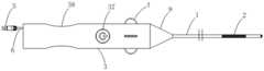
图1为本发明可调弯度的射频消融微导管一个实施例的结构示意图;Fig. 1 is the structure diagram of an embodiment of the radiofrequency ablation microcatheter with adjustable curvature of the present invention;
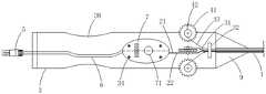
图2为图1射频消融导管的内部结构示意图;Fig. 2 is a schematic diagram of the internal structure of the radiofrequency ablation catheter in Fig. 1;
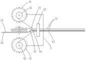
图3为图1中调弯装置的结构示意图;Fig. 3 is a schematic structural view of the bending device in Fig. 1;
图4为图1中调弯装置另一视角的排布示意图;Fig. 4 is a schematic diagram of the arrangement of the bending device in Fig. 1 from another perspective;
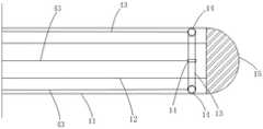
图5为图1中微导管管体的内部结构示意图;Fig. 5 is a schematic diagram of the internal structure of the microcatheter body in Fig. 1;
图6为图5微导管管体拉弯后的结构示意图;Fig. 6 is the schematic diagram of the structure of the microcatheter body in Fig. 5 after stretching and bending;
图7为微导管管体进入人体血管后的示意图。Fig. 7 is a schematic diagram of a microcatheter body entering a blood vessel of a human body.
图中标号:1-微导管管体;11-外层管;12-内层管;13-固定环;14-拉伸环;15-UV胶头;2-射频线圈;21-射频加热线;22-温度感应线;3-手柄;31-钢丝导向柱;32-导向盘;321-钢丝通过孔;322-加热线通过孔;323-感应线通过孔;33-感应线导向柱;34-定位柱;35-安装架;37-开关按钮;38-握持部;4-调弯装置;41-调节齿轮;42-从动盘;43-拉伸钢丝;5-主机连接头;6-连接尾线;7-启动芯片;71-启动按钮;9-防护罩;10-人体血管。Labels in the figure: 1-microcatheter tube body; 11-outer tube; 12-inner tube; 13-fixing ring; 14-stretching ring; 15-UV glue head; 2-radio frequency coil; 21-radio frequency heating wire ; 22-temperature induction line; 3-handle; 31-steel wire guide column; 32-guide plate; 321-steel wire through hole; 322-heating wire through hole; -Positioning column; 35-Installation frame; 37-Switch button; 38-Grip part; 4-Bending device; 41-Adjusting gear; -connect the tail wire; 7-start chip; 71-start button; 9-protective cover; 10-human blood vessel.
具体实施方式Detailed ways
下面将对本发明实施例中的技术方案进行清楚、完整地描述,显然,所描述的实施例仅仅是本发明的一部分实施例,而不是全部的实施例。基于本发明中的实施例,本领域普通技术人员所获得的所有其他实施例,都属于本发明保护的范围。The technical solutions in the embodiments of the present invention will be clearly and completely described below, obviously, the described embodiments are only some of the embodiments of the present invention, not all of the embodiments. All other embodiments obtained by persons of ordinary skill in the art based on the embodiments of the present invention belong to the protection scope of the present invention.
下面将结合实施例来详细说明本发明。需要说明的是,在不冲突的情况下,本发明中的实施例及实施例中的特征可以相互组合。The present invention will be described in detail below in conjunction with examples. It should be noted that, in the case of no conflict, the embodiments of the present invention and the features in the embodiments can be combined with each other.
针对现有导管无法顺畅地到达病变部位的问题,本发明提供了一种射频消融微导管,本发明提供的射频消融微导管内部没有导丝腔,在应用于静脉曲张的治疗手术过程中,可以不依靠导丝牵引到达病变部位,直接通过调节微导管管体1的弯度,使得微导管管体1适应不同迂曲角度的血管,顺畅地到达病变部位。此外,由于本发明的射频消融微导管内部没有导丝腔,可以将微导管管体1制作成外径更小(比如外径为5F)的微导管管体1,以治疗更多更细的静脉血管。Aiming at the problem that the existing catheter cannot reach the lesion smoothly, the present invention provides a radiofrequency ablation microcatheter. The radiofrequency ablation microcatheter provided by the present invention does not have a guide wire cavity inside, and can be used in the treatment of varicose veins. Instead of relying on guide wire traction to reach the lesion site, the
如图1所示,本发明的射频消融微导管包括微导管管体1、射频线圈2、手柄3和调弯装置4,其中,射频线圈2缠绕在微导管管体1的远端,射频线圈2的头端和尾端采用粘胶固定,射频线圈2加热后可用于将其射频能量传递给病变血管组织,病变的血管受热皱缩,纤维层出现炎症变性以完全堵塞曲张的血管,达到治疗的目的;手柄3连接于微导管管体1的近端,其连接方式可选为胶粘固定;调弯装置4设置在手柄3上且连接于微导管管体1,用于对所述微导管管体1进行弯度调节,以适应不同迂曲角度的血管,顺畅地到达病变部位。As shown in Figure 1, the radiofrequency ablation microcatheter of the present invention comprises a
需要说明的是,文中所述的近端为靠近手术操作者的一端,远端为远离手术操作者的一端。It should be noted that the proximal end mentioned herein is the end close to the operator, and the distal end is the end far away from the operator.
如图2至图4所示,本发明具体实施例中,调弯装置4包括:齿轮组件和拉伸钢丝43,齿轮组件设置在手柄3上;拉伸钢丝43的一端连接于齿轮组件,另一端连接于微导管管体1的远端;旋转齿轮组件可带动拉伸钢丝43收缩,使得微导管管体1发生形变而弯曲。As shown in Figures 2 to 4, in a specific embodiment of the present invention, the bending device 4 includes: a gear assembly and a stretched
其中,齿轮组件包括调节齿轮41和从动盘42,调节齿轮41设置在手柄3上;从动盘42固定在调节齿轮41上,可跟随调节齿轮41转动而转动;拉伸钢丝43的一端缠绕在从动盘42上,另一端连接于微导管管体1的远端内壁;旋转调节齿轮41可带动从动盘42转动,并带动拉伸钢丝43收缩,使得微导管管体1发生形变而弯曲。Wherein, the gear assembly includes an
需要说明的是,在需要将微导管管体1进行弯度调节时,手动旋转调节齿轮41带动从动盘42转动,进而带动拉伸钢丝43收缩,便可以使得微导管管体1发生形变而弯曲。It should be noted that when it is necessary to adjust the curvature of the
本实施例中,调节齿轮41的部分位于手柄3的内部,部分外露于手柄3,并相对于手柄3可转动。手柄3上设置有安装架35,安装架35大致呈U型架,调节齿轮41和从动盘42对应设置有安装孔(未标示),并通过安装孔套设在安装架35上,这样可实现调节齿轮41和从动盘42的安装,且调节齿轮41和从动盘42可相对于安装架35发生转动,以实现拉伸钢丝43的收缩和释放。In this embodiment, part of the
如图5和图6,本发明具体实施例中,微导管管体1包括相套设的内层管12和外层管11,外层管11的远端内表面上设置有固定环13,固定环13通过强力胶水粘接在外层管11的内表面上;固定环13上安装有拉伸环14,拉伸环14位于内层管12和外层管11之间;手柄3的远端面设置有连接孔(未标示),连接孔的内径与外层管11的外径相适配,外层管11的近端外壁固定连接于连接孔的内壁,可选为外层管11的近端外壁胶粘固定于连接孔的内壁;拉伸钢丝43穿过连接孔并穿设于内层管12和外层管11之间,且拉伸钢丝43的穿设端固定连接于拉伸环14(其固定连接方式为锡焊焊接)。如此的结构设计,在需要将微导管管体1进行弯度调节时,手动旋转调节齿轮41带动从动盘42转动,进而带动拉伸钢丝43收缩,拉伸钢丝43会拉动拉伸环14,使得相应的固定环13受力,促使得微导管管体1发生形变而弯曲。As shown in Fig. 5 and Fig. 6, in a specific embodiment of the present invention, the
再次参照图4、图5和图6,本发明具体实施例中,调节齿轮41设置为四个,四个调节齿轮41沿手柄3的周向均匀分布,也即,调节齿轮41在手柄3中呈上下左右垂直排布,在手柄3的周向方向上,相邻两个调节齿轮41的夹角为90°;从动盘42设置为四个,分别对应固定在四个调节齿轮41上,可实现与相应的调节齿轮41同步旋转;相应地,拉伸环14设置有四个,四个拉伸环14沿固定环13的周向均匀分布;拉伸钢丝43设置为四条,四条拉伸钢丝43的一端分别缠绕在四个从动盘42上,另一端对应连接于四个拉伸环14上,并且四条拉伸钢丝43均穿设于外层管11和内层管12之间。如此的结构设计,通过调节四个调节齿轮41的旋转,带动相应从动盘42转动,从动盘42转动可牵引对应的拉伸钢丝43做直线运动,拉伸钢丝43进而拉动相应的拉伸环14,从而带动相应的固定环13一起进行运动,调节不同点位的调节齿轮41,会使得对应点位的固定环13受拉,进而使得微导管管体1发生形变而弯曲。Referring again to Fig. 4, Fig. 5 and Fig. 6, in the specific embodiment of the present invention, the number of adjustment gears 41 is set to four, and the four adjustment gears 41 are evenly distributed along the circumference of the
需要说明的是,四个调节齿轮41和相应的从动盘42均通过安装架35固定在手柄3手柄3上,且相对于安装架35可旋转。It should be noted that the four adjusting gears 41 and the corresponding driven
进一步地,为了使得四条拉伸钢丝43走线布局更合理,手柄3的内部设置有导向盘32和四个钢丝导向柱34,导向盘32靠近手柄3的远端设置,导向盘32上设有四个钢丝通过孔321,用于使得四条拉伸钢丝43通过;四个钢丝导向柱31均设置于导向盘32的内侧,且分别对应四个钢丝通过孔321设置;四个钢丝导向柱31和导向盘32用于对四条拉伸钢丝43进行导向和定位,也即是,四条拉伸钢丝43通过相应的钢丝导向柱34顺滑的改变走线的方向,再通过导向盘32对四条拉伸钢丝43进行轨道定位。Further, in order to make the routing layout of the four stretched
本发明的调弯装置4操作较为简单,手术过程中手术操作者可以在单手握持手柄3时,同时手动进行两个方向的弯度调节。The operation of the bending adjustment device 4 of the present invention is relatively simple. During the operation, the operator can manually adjust the curvature in two directions while holding the
如图1和图2所示,射频消融微导管还包括:启动芯片7、连接尾线6和主机连接头5,其中启动芯片7设置在手柄3的内部,启动芯片7与射频线圈2通过射频加热线21和温度感应线22连接,射频加热线21用于加热射频线圈2,温度感应线22用于实时感应射频线圈2的温度;启动芯片7上设置启动按钮71;连接尾线6的一端连接于启动芯片7,另一端贯穿并外露于手柄3的近端部;主机连接头5连接于连接尾线6的外露端。当微导管管体1进入到血管内的病变部位后,将主机连接头5与外部主机连接,按压启动芯片7上的启动按钮71便可使得启动芯片7的电路接通,通过射频加热线21可加热射频线圈2,射频线圈2发热后会将射频能量传递给病变血管组织,病变的血管受热皱缩,纤维层出现炎症变性以完全堵塞曲张的血管,达到治疗的目的。As shown in Figures 1 and 2, the radiofrequency ablation microcatheter also includes: a starting chip 7, a connecting
需要说明的是,射频加热线21和温度感应线22是走线在内层管12和外层管11的间隙内,射频线圈2是缠绕在外层管11上,外层管11于射频线圈2处开设有加热线穿设孔(未图示)和感应线穿设孔(未图示),射频加热线21和温度感应线22对应穿过加热线穿设孔和感应线穿设孔后与射频线圈2相连。It should be noted that the radio
如图2所示,本发明具体实施例中,启动芯片7通过定位柱34固定在手柄3内,具体地,手柄3的内部设置有定位柱34,启动芯片7对应设置有定位孔,启动芯片7通过定位孔与定位柱34的配合固定在手柄3内。可选地,定位柱34间隔设置有四个,定位孔对应设置有四个,如此可以保证启动芯片7的设置稳固性。As shown in Figure 2, in a specific embodiment of the present invention, the start-up chip 7 is fixed in the
进一步地,手柄3对应启动按钮71处设置有可活动的开关按钮37,在主机连接头5与外部主机连接后,可手动按压手柄3上的开关按钮37,开关按钮37接触并按压启动按钮71便可使得启动芯片7上的电路接通,实现对射频线圈2进行加热。具体地,手柄3对应启动按钮71处设置有贯穿孔(未标示),开关按钮37穿设于该贯穿孔内,且开关按钮37与启动按钮71弹性连接(可采用弹簧),手动按压开关按钮37可接触并按压启动按钮71。Further, the
进一步地,导向盘32还设置有加热线通过孔322和感应线通过孔323,也即是导向盘32上设置有六个通过孔;手柄3的内部还设置有加热线导向柱(未图示)和感应线导向柱33,分别对应于加热线通过孔322和感应线通过孔323设置,用于对射频加热线21和温度感应线22进行导向和定位,使其走线布局更加合理。Further, the
进一步地,再次参照图1和图2,射频消融微导管还包括防护罩9,防护罩9设置在手柄3的远端,微导管管体1的近端穿设于防护罩9内并固定连接于所述手柄3的远端;防护罩9大致呈锥形,可以用来保护微导管管体1在操作手柄3时不会弯折或断裂。Further, referring to Fig. 1 and Fig. 2 again, the radiofrequency ablation microcatheter also includes a
需要说明的是,防护罩9与手柄3远端的连接方式为胶粘连接,操作简单且连接较为牢固。It should be noted that the connection between the
本发明的手柄3的外轮廓为圆柱形,其近端外表面内凹结构为握持部38,以方便手术操作者人手握持手柄3。手柄3可选为分体壳体结构,以方便手柄3内部各个部件的装配操作。The outer contour of the
进一步地,如图1、图5和图6所示,微导管管体1的远端设置有UV胶头15,UV胶头15为半球形,通过紫外灯固化而成,UV胶体柔软带有弹性,不会刮伤血管。Further, as shown in Figure 1, Figure 5 and Figure 6, the distal end of the
如图7所示,在采用本发明的射频消融微导管进行治疗静脉曲张时,可以先通过体外超声波探头对人体血管10的情况进行观察,在微导管管体1进入人体血管10,并到达血管分叉处或弯曲处时,可以通过操作调弯装置4使得微导管管体1变形弯曲,顺畅而又高效地到达血管迂曲或很狭窄的位置。该操作简单易行,使得手术过程更加安全可靠。As shown in Figure 7, when using the radiofrequency ablation microcatheter of the present invention to treat varicose veins, the situation of the
以上所述仅为本发明的优选实施例,并不用于限制本发明,对于本领域的技术人员来说,本发明可以有各种更改和变化。凡在本发明的精神和原则之内,所作的任何修改、等同替换、改进等,均应包含在本发明的保护范围之内。The above descriptions are only preferred embodiments of the present invention, and are not intended to limit the present invention. For those skilled in the art, the present invention may have various modifications and changes. Any modifications, equivalent replacements, improvements, etc. made within the spirit and principles of the present invention shall be included within the protection scope of the present invention.
Claims (10)
Priority Applications (1)
| Application Number | Priority Date | Filing Date | Title |
|---|---|---|---|
| CN202210917984.4ACN115381549B (en) | 2022-08-01 | 2022-08-01 | Radio frequency ablation microcatheter with adjustable camber |
Applications Claiming Priority (1)
| Application Number | Priority Date | Filing Date | Title |
|---|---|---|---|
| CN202210917984.4ACN115381549B (en) | 2022-08-01 | 2022-08-01 | Radio frequency ablation microcatheter with adjustable camber |
Publications (2)
| Publication Number | Publication Date |
|---|---|
| CN115381549Atrue CN115381549A (en) | 2022-11-25 |
| CN115381549B CN115381549B (en) | 2024-12-17 |
Family
ID=84119462
Family Applications (1)
| Application Number | Title | Priority Date | Filing Date |
|---|---|---|---|
| CN202210917984.4AActiveCN115381549B (en) | 2022-08-01 | 2022-08-01 | Radio frequency ablation microcatheter with adjustable camber |
Country Status (1)
| Country | Link |
|---|---|
| CN (1) | CN115381549B (en) |
Citations (6)
| Publication number | Priority date | Publication date | Assignee | Title |
|---|---|---|---|---|
| CN1625371A (en)* | 2001-11-29 | 2005-06-08 | 麦迪威公司 | Radio frequency based catheter system with improved deflection and steering mechanism |
| CN102688093A (en)* | 2012-06-20 | 2012-09-26 | 深圳市惠泰医疗器械有限公司 | Renal artery cold saline water radio frequency ablation controllable electrode catheter |
| CN110974406A (en)* | 2019-12-31 | 2020-04-10 | 杭州堃博生物科技有限公司 | Detection mechanism, radiofrequency ablation catheter and radiofrequency ablation system |
| CN111067617A (en)* | 2019-12-27 | 2020-04-28 | 苏州恒瑞宏远医疗科技有限公司 | Radiofrequency closed catheter and method of making the same |
| CN114010305A (en)* | 2021-11-17 | 2022-02-08 | 上海玮琅医疗科技有限公司 | Radio frequency ablation catheter and system |
| CN114191068A (en)* | 2020-09-18 | 2022-03-18 | Tau-Pnu医疗有限公司 | Atrial fibrillation treatment catheter and atrial fibrillation treatment method using the same |
- 2022
- 2022-08-01CNCN202210917984.4Apatent/CN115381549B/enactiveActive
Patent Citations (6)
| Publication number | Priority date | Publication date | Assignee | Title |
|---|---|---|---|---|
| CN1625371A (en)* | 2001-11-29 | 2005-06-08 | 麦迪威公司 | Radio frequency based catheter system with improved deflection and steering mechanism |
| CN102688093A (en)* | 2012-06-20 | 2012-09-26 | 深圳市惠泰医疗器械有限公司 | Renal artery cold saline water radio frequency ablation controllable electrode catheter |
| CN111067617A (en)* | 2019-12-27 | 2020-04-28 | 苏州恒瑞宏远医疗科技有限公司 | Radiofrequency closed catheter and method of making the same |
| CN110974406A (en)* | 2019-12-31 | 2020-04-10 | 杭州堃博生物科技有限公司 | Detection mechanism, radiofrequency ablation catheter and radiofrequency ablation system |
| CN114191068A (en)* | 2020-09-18 | 2022-03-18 | Tau-Pnu医疗有限公司 | Atrial fibrillation treatment catheter and atrial fibrillation treatment method using the same |
| CN114010305A (en)* | 2021-11-17 | 2022-02-08 | 上海玮琅医疗科技有限公司 | Radio frequency ablation catheter and system |
Also Published As
| Publication number | Publication date |
|---|---|
| CN115381549B (en) | 2024-12-17 |
Similar Documents
| Publication | Publication Date | Title |
|---|---|---|
| US8298215B2 (en) | Guidewire tipped laser fiber | |
| JP5657236B2 (en) | Prevention of kinking of catheter irrigation tube | |
| JP4877847B2 (en) | Catheter with flexible pre-shaped tip | |
| US7977658B2 (en) | Flexible infrared delivery apparatus and method | |
| EP3422965A1 (en) | Eustachian tube modification | |
| JP2008501444A (en) | Method and device for directional resection of tissue | |
| US20120116377A1 (en) | Apparatus utilizing a guide wire to maneuver heating element and probe for treating damaged spinal discs | |
| MX2010009306A (en) | Endoluminal laser ablation device and method for treating veins. | |
| JP2001095815A (en) | Microwave coagulation applicator | |
| JP2015510142A (en) | Optical fiber configured to emit radiation by bending | |
| WO2001008575A3 (en) | Optical fiber basket device for cardiac photoablation | |
| WO2024060828A1 (en) | Ultrasonic ablation catheter and ultrasonic ablation device | |
| JP2025530755A (en) | Targeted ablation system, control method, device, medium, and electronic device | |
| CN104739504B (en) | Radiofrequency ablation device for spinal neoplasms operation | |
| CN115381549A (en) | A microcatheter for radiofrequency ablation with adjustable curvature | |
| CN116570363B (en) | Radio frequency catheter | |
| CN219681450U (en) | Endoscopic resection and drainage column pigtail stent set | |
| CN115381548B (en) | Radio frequency ablation catheter capable of locking connection tail wire | |
| KR101425642B1 (en) | Apparatus for curing varicose vein | |
| JP2024531325A (en) | Electrode device for blocking or modulating nerves in the body | |
| KR101415069B1 (en) | Thermotherapy apparatus of varicose vein and thermotherapy method thereof | |
| CN117281612B (en) | Photosensitizer inducing device | |
| CN219645862U (en) | Balloon filling type radio frequency ablation catheter | |
| US20240108858A1 (en) | Multi-function catheter shaft tool | |
| CN222885383U (en) | A plasma electrode for hip arthroscopy |
Legal Events
| Date | Code | Title | Description |
|---|---|---|---|
| PB01 | Publication | ||
| PB01 | Publication | ||
| SE01 | Entry into force of request for substantive examination | ||
| SE01 | Entry into force of request for substantive examination | ||
| GR01 | Patent grant | ||
| GR01 | Patent grant |