CN115381521A - Clamping and sleeving device for umbilical cord - Google Patents
Clamping and sleeving device for umbilical cordDownload PDFInfo
- Publication number
- CN115381521A CN115381521ACN202210815883.6ACN202210815883ACN115381521ACN 115381521 ACN115381521 ACN 115381521ACN 202210815883 ACN202210815883 ACN 202210815883ACN 115381521 ACN115381521 ACN 115381521A
- Authority
- CN
- China
- Prior art keywords
- umbilical cord
- clamp
- clamping
- limiting
- umbilical
- Prior art date
- Legal status (The legal status is an assumption and is not a legal conclusion. Google has not performed a legal analysis and makes no representation as to the accuracy of the status listed.)
- Granted
Links
- 210000003954umbilical cordAnatomy0.000titleclaimsabstractdescription169
- 230000007246mechanismEffects0.000claimsabstractdescription23
- 238000001125extrusionMethods0.000claimsabstractdescription16
- 210000004369bloodAnatomy0.000claimsabstractdescription11
- 239000008280bloodSubstances0.000claimsabstractdescription11
- 239000000463materialSubstances0.000claimsdescription19
- 239000013013elastic materialSubstances0.000claimsdescription6
- VYPSYNLAJGMNEJ-UHFFFAOYSA-NSilicium dioxideChemical compoundO=[Si]=OVYPSYNLAJGMNEJ-UHFFFAOYSA-N0.000claimsdescription4
- 239000000741silica gelSubstances0.000claimsdescription4
- 229910002027silica gelInorganic materials0.000claimsdescription4
- 229920001971elastomerPolymers0.000claimsdescription3
- 239000006261foam materialSubstances0.000claimsdescription3
- 238000009434installationMethods0.000abstractdescription5
- 230000009471actionEffects0.000description4
- 238000000034methodMethods0.000description4
- 208000015181infectious diseaseDiseases0.000description3
- 230000008569processEffects0.000description3
- 208000035049Blood-Borne InfectionsDiseases0.000description2
- 208000019300CLIPPERSDiseases0.000description2
- 229920000742CottonPolymers0.000description2
- 230000008901benefitEffects0.000description2
- 208000021930chronic lymphocytic inflammation with pontine perivascular enhancement responsive to steroidsDiseases0.000description2
- 230000007547defectEffects0.000description2
- 230000000694effectsEffects0.000description2
- 210000004700fetal bloodAnatomy0.000description2
- 229920002529medical grade siliconePolymers0.000description2
- 239000004033plasticSubstances0.000description2
- 238000010008shearingMethods0.000description2
- 230000007704transitionEffects0.000description2
- 241000894006BacteriaSpecies0.000description1
- 210000001015abdomenAnatomy0.000description1
- 230000009286beneficial effectEffects0.000description1
- 238000010586diagramMethods0.000description1
- 239000012567medical materialSubstances0.000description1
- 238000012986modificationMethods0.000description1
- 230000004048modificationEffects0.000description1
- 230000003169placental effectEffects0.000description1
- 239000012780transparent materialSubstances0.000description1
Images


Classifications
- A—HUMAN NECESSITIES
- A61—MEDICAL OR VETERINARY SCIENCE; HYGIENE
- A61B—DIAGNOSIS; SURGERY; IDENTIFICATION
- A61B17/00—Surgical instruments, devices or methods
- A61B17/12—Surgical instruments, devices or methods for ligaturing or otherwise compressing tubular parts of the body, e.g. blood vessels or umbilical cord
- A61B17/128—Surgical instruments, devices or methods for ligaturing or otherwise compressing tubular parts of the body, e.g. blood vessels or umbilical cord for applying or removing clamps or clips
- A—HUMAN NECESSITIES
- A61—MEDICAL OR VETERINARY SCIENCE; HYGIENE
- A61B—DIAGNOSIS; SURGERY; IDENTIFICATION
- A61B17/00—Surgical instruments, devices or methods
- A61B17/12—Surgical instruments, devices or methods for ligaturing or otherwise compressing tubular parts of the body, e.g. blood vessels or umbilical cord
- A61B17/12009—Implements for ligaturing other than by clamps or clips, e.g. using a loop with a slip knot
- A—HUMAN NECESSITIES
- A61—MEDICAL OR VETERINARY SCIENCE; HYGIENE
- A61B—DIAGNOSIS; SURGERY; IDENTIFICATION
- A61B17/00—Surgical instruments, devices or methods
- A61B17/12—Surgical instruments, devices or methods for ligaturing or otherwise compressing tubular parts of the body, e.g. blood vessels or umbilical cord
- A61B17/122—Clamps or clips, e.g. for the umbilical cord
- A—HUMAN NECESSITIES
- A61—MEDICAL OR VETERINARY SCIENCE; HYGIENE
- A61B—DIAGNOSIS; SURGERY; IDENTIFICATION
- A61B17/00—Surgical instruments, devices or methods
- A61B17/28—Surgical forceps
- A61B17/2812—Surgical forceps with a single pivotal connection
- A—HUMAN NECESSITIES
- A61—MEDICAL OR VETERINARY SCIENCE; HYGIENE
- A61B—DIAGNOSIS; SURGERY; IDENTIFICATION
- A61B17/00—Surgical instruments, devices or methods
- A61B17/28—Surgical forceps
- A61B17/2812—Surgical forceps with a single pivotal connection
- A61B17/282—Jaws
- A—HUMAN NECESSITIES
- A61—MEDICAL OR VETERINARY SCIENCE; HYGIENE
- A61B—DIAGNOSIS; SURGERY; IDENTIFICATION
- A61B17/00—Surgical instruments, devices or methods
- A61B17/12—Surgical instruments, devices or methods for ligaturing or otherwise compressing tubular parts of the body, e.g. blood vessels or umbilical cord
- A61B17/12009—Implements for ligaturing other than by clamps or clips, e.g. using a loop with a slip knot
- A61B2017/12018—Elastic band ligators
Landscapes
- Health & Medical Sciences (AREA)
- Surgery (AREA)
- Life Sciences & Earth Sciences (AREA)
- Heart & Thoracic Surgery (AREA)
- Molecular Biology (AREA)
- Veterinary Medicine (AREA)
- Engineering & Computer Science (AREA)
- Biomedical Technology (AREA)
- Public Health (AREA)
- Medical Informatics (AREA)
- Nuclear Medicine, Radiotherapy & Molecular Imaging (AREA)
- Animal Behavior & Ethology (AREA)
- General Health & Medical Sciences (AREA)
- Reproductive Health (AREA)
- Vascular Medicine (AREA)
- Ophthalmology & Optometry (AREA)
- Surgical Instruments (AREA)
Abstract
Translated fromChinese
Description
Translated fromChinese技术领域technical field
本发明属于医用器具技术领域,具体涉及一种用于脐带的夹紧套接装置。The invention belongs to the technical field of medical appliances, and in particular relates to a clamping socket device for an umbilical cord.
背景技术Background technique
脐带夹剪器用于产道分娩或剖宫产时胎盘脐带的剪断操作,可取代传统的多步骤操作过程。其结构包括一对夹剪活动杆,还包括脐带夹、关节轴,一对夹剪活动杆通过关节轴可相对转动地连接在一起,脐带夹包括一对夹体,一对夹体分别安装在两个夹剪活动杆夹剪段的相对侧上,脐带夹还包括与一对夹体根部相连的、围绕关节轴的过渡连接部,一对夹体的相对侧均设有起剪断作用的锯齿;剪断脐带时,可将脐带放在一对夹体之间,然后连续有力的剪断脐带,锯齿可加快脐带的断裂速度。The umbilical cord clipper is used for cutting the placental umbilical cord during birth canal delivery or cesarean section, and can replace the traditional multi-step operation process. Its structure includes a pair of clamping and shearing movable rods, and also includes an umbilical cord clamp and a joint shaft. A pair of clamping and shearing movable rods are relatively rotatably connected together through the joint shaft. On the opposite sides of the clipping section of the two clipping movable rods, the umbilical cord clip also includes a transition connection part connected with the root of a pair of clip bodies and around the joint axis, and the opposite sides of the pair of clip bodies are provided with sawtooth for cutting ; When cutting the umbilical cord, the umbilical cord can be placed between a pair of clamps, and then the umbilical cord can be cut off continuously, and the sawtooth can speed up the breaking speed of the umbilical cord.
但上述结构的脐带夹剪器存在以下缺陷:But there is following defect in the umbilical cord clipper of above-mentioned structure:
1、锯齿在切断脐带和夹体在夹住脐带基本是同时进行,这样会导致锯齿剪断脐带时,位于两夹体之间的脐带中会有血液流出,延长了脐带的脱落时间,增加了感染几率。1. The sawtooth cuts the umbilical cord and the clip body clamps the umbilical cord at the same time. This will cause blood to flow out of the umbilical cord between the two clips when the serration cuts the umbilical cord, which prolongs the time for the umbilical cord to fall off and increases infection. probability.
2.在锯齿夹紧脐带后,需要使用扩张钳将脐带结扎圈撑开,套接于脐带上,增加了医护人员的操作负担,也增加了使用成本。2. After the umbilical cord is clamped by the serrations, it is necessary to use expansion forceps to stretch the umbilical cord ligation ring and socket it on the umbilical cord, which increases the operating burden of medical staff and also increases the cost of use.
针对上述技术问题,故需要进行改进。For above-mentioned technical problem, so need to improve.
发明内容Contents of the invention
本发明是为了克服上述现有技术中的缺陷,提供一种设计巧妙,结构简单,能将需要剪切的脐带血液排空后再夹紧,并且可以将脐带结扎圈套接于脐带上的用于脐带的夹紧套接装置。The purpose of the present invention is to overcome the above-mentioned defects in the prior art, and to provide a device with ingenious design and simple structure, which can clamp the umbilical cord blood that needs to be cut after emptying, and can fit the umbilical cord ligation ring on the umbilical cord. Clamping sleeve for umbilical cord.
为了达到以上目的,本发明所采用的技术方案是:一种用于脐带的夹紧套接装置,包括两个通过铰接轴铰接的钳体,所述钳体上半部设有钳口,所述钳体下半部为手柄,位于两个所述钳体之间用于夹持脐带的脐带夹,脐带夹设置有两个,钳口内布设有用于挤压脐带内血液的挤压块;挤压块内形成有内凹槽,脐带夹装配于内凹槽内;所述脐带夹的底部固设有连接柱,连接柱上安装有脐带套接机构,与此相对应的,钳体的一侧形成有用于脐带套接机构穿过的安装孔。In order to achieve the above purpose, the technical solution adopted in the present invention is: a clamping and socketing device for umbilical cords, comprising two clamp bodies hinged by hinge shafts, the upper half of the clamp bodies is provided with a jaw, so The lower part of the clamp body is a handle, which is located between the two clamp bodies and is used for clamping the umbilical cord. There are two cord clamps, and an extrusion block for squeezing the blood in the umbilical cord is arranged in the jaws; An inner groove is formed in the pressing block, and the umbilical cord clamp is assembled in the inner groove; the bottom of the umbilical cord clamp is fixed with a connecting column, and an umbilical cord socket mechanism is installed on the connecting column. Correspondingly, one part of the clamp body The side is formed with a mounting hole for the umbilical cord sleeve mechanism to pass through.
作为本发明的一种优选方式,所述连接柱包括柱本体和限位帽,限位帽固设于柱本体顶部,柱本体底部固设于脐带夹上,并且,柱本体的外径小于限位帽的外径。As a preferred mode of the present invention, the connecting column includes a column body and a limit cap, the limit cap is fixed on the top of the column body, the bottom of the column body is fixed on the umbilical cord clamp, and the outer diameter of the column body is less than the limit The outer diameter of the bit cap.
作为本发明的一种优选方式,所述脐带套接机构包括圈体,圈体中部形成有用于夹持脐带的夹持孔;夹持孔内穿过拉线,拉线连接有操作手柄;圈体套接于连接柱的柱本体上。As a preferred mode of the present invention, the umbilical cord socket mechanism includes a loop body, and a clamping hole for clamping the umbilical cord is formed in the middle of the loop body; a pull wire passes through the clamp hole, and the pull wire is connected to an operating handle; the loop body sleeve Connected to the column body of the connecting column.
作为本发明的一种优选方式,所述操作手柄的两侧沿其长度方向对应设置多个防滑条。As a preferred mode of the present invention, a plurality of anti-slip strips are correspondingly provided on both sides of the operating handle along its length direction.
作为本发明的一种优选方式,所述操作手柄的宽度小于安装孔的宽度。As a preferred mode of the present invention, the width of the operating handle is smaller than the width of the installation hole.
作为本发明的一种优选方式,所述圈体的长度与柱本体高度相一致。As a preferred mode of the present invention, the length of the ring body is consistent with the height of the column body.
作为本发明的一种优选方式,所述圈体套接于柱本体上,圈体的外侧与限位帽外侧在同一水平面上。As a preferred mode of the present invention, the ring body is sleeved on the column body, and the outer side of the ring body is on the same level as the outer side of the limit cap.
作为本发明的一种优选方式,所述圈体为柔性弹性材料制成。As a preferred mode of the present invention, the ring body is made of flexible elastic material.
作为本发明的一种优选方式,所述柔性弹性材料为橡胶或医用硅胶。As a preferred mode of the present invention, the flexible elastic material is rubber or medical silicone.
作为本发明的一种优选方式,所述钳口的一侧顶部布设有限位凸起,与此相对应的,钳口的另一侧顶部布设有限位凹槽;限位凸起装配于限位凹槽内时,脐带夹用于夹紧脐带。As a preferred mode of the present invention, a limiting protrusion is arranged on the top of one side of the jaw, and correspondingly, a limiting groove is arranged on the top of the other side of the jaw; the limiting protrusion is assembled on the limiting When in the groove, the umbilical clamp is used to clamp the umbilical cord.
作为本发明的一种优选方式,所述挤压块为高回弹材质制成。As a preferred mode of the present invention, the extruded block is made of high resilience material.
作为本发明的一种优选方式,所述高回弹材质制为硅胶层、EVA材料层、phylong材料层、PU材料层、TPU材料层或泡棉材料层中的一种。As a preferred mode of the present invention, the high resilience material is made of one of silica gel layer, EVA material layer, phylong material layer, PU material layer, TPU material layer or foam material layer.
作为本发明的一种优选方式,所述限位凸起与限位凹槽位于两个脐带夹之间,其中,限位凸起与限位凹槽设置有两个。As a preferred mode of the present invention, the limiting protrusion and the limiting groove are located between two umbilical cord clamps, wherein there are two limiting protrusions and limiting grooves.
作为本发明的一种优选方式,所述两个脐带夹对称布设于钳口两侧。As a preferred mode of the present invention, the two umbilical cord clamps are arranged symmetrically on both sides of the jaws.
作为本发明的一种优选方式,所述两个脐带夹之间的距离为25mm~30mm。As a preferred mode of the present invention, the distance between the two umbilical cord clamps is 25mm-30mm.
作为本发明的一种优选方式,所述钳体的两手柄上沿其长度方向对应设置多个防滑纹。As a preferred mode of the present invention, the two handles of the pliers body are provided with a plurality of anti-slip lines correspondingly along the length direction thereof.
作为本发明的一种优选方式,所述多个防滑纹等距布设于手柄上,防滑纹顶部布设有限位块。As a preferred mode of the present invention, the plurality of anti-slip lines are equidistantly arranged on the handle, and a limit block is arranged on the top of the anti-slip lines.
作为本发明的一种优选方式,所述手柄、防滑纹和限位块固定连接,一体成型。As a preferred mode of the present invention, the handle, the anti-skid pattern and the limit block are fixedly connected and integrally formed.
本发明的有益效果是:The beneficial effects of the present invention are:
1.本发明结构简单,设计巧妙,通过设置在钳口内布设挤压块,有用于挤压脐带内血液的挤压块,可以在脐带夹夹紧脐带前,通过挤压块将两脐带夹之间脐带内的血液排空后,然后通过两个脐带夹将脐带夹紧,这样脐带中就不会有血液流出,进而避免血源性疾病的传染,提高了安全性能。1. The present invention is simple in structure and ingenious in design. By arranging the extrusion block in the jaws, there is an extrusion block for squeezing the blood in the umbilical cord. Before the umbilical cord is clamped, the two umbilical cords can be clamped by the extrusion block. After the blood in the umbilical cord is emptied, the umbilical cord is clamped by two umbilical cord clamps, so that no blood will flow out of the umbilical cord, thereby avoiding the infection of blood-borne diseases and improving safety performance.
2.本发明通过在脐带夹的底部固设有连接柱,连接柱上安装有脐带套接机构,可以在锯齿夹紧脐带后,通过脐带套接机构将脐带结扎圈套接在脐带上,提高操作效率的同时,也节约了使用成本。2. In the present invention, a connecting column is fixed at the bottom of the umbilical cord clamp, and an umbilical cord socket mechanism is installed on the connecting column. After the umbilical cord is clamped by the sawtooth, the umbilical cord ligature ring can be socketed on the umbilical cord through the umbilical cord socket mechanism, which improves the operation. While improving efficiency, it also saves the cost of use.
附图说明Description of drawings
图1是本发明实施例结构示意图(一);Fig. 1 is a schematic view of the structure of an embodiment of the present invention (1);
图2是本发明实施例结构示意图(二);Fig. 2 is a schematic structural view of an embodiment of the present invention (two);
图3是本发明实施例主视图;Fig. 3 is a front view of an embodiment of the present invention;
图4是本发明实施例A向局部放大图;Fig. 4 is the partial enlarged view of embodiment A of the present invention;
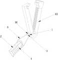
图5是本发明实施例脐带套接机构的结构示意图;Fig. 5 is a structural schematic diagram of an umbilical cord socket mechanism according to an embodiment of the present invention;
图6是本发明实施例钳体与连接柱的结构示意图;Fig. 6 is a schematic structural view of the clamp body and the connecting column of the embodiment of the present invention;
图中附图标记:圈体1,操作手柄2,夹持孔3,防滑条4,拉线6,铰接轴9,齿条14,齿孔15,钳体60,钳口61,手柄62,脐带夹63,夹臂63-1,挤压块64,内凹槽65,防滑纹66,限位块67,限位凸起68,限位凹槽69,脐带套接机构70,安装孔80,连接柱90,柱本体91,限位帽92。Reference signs in the figure:
具体实施方式Detailed ways
下面结合附图对本发明实施例作详细说明。Embodiments of the present invention will be described in detail below in conjunction with the accompanying drawings.
实施例:Example:
如图1-6所示;一种用于脐带的夹紧套接装置,包括两个通过铰接轴9铰接的钳体60,钳体60上半部设有钳口61,钳体60下半部为手柄62,位于两个所述钳体60之间用于夹持脐带的脐带夹63,脐带夹63设置有两个,两个脐带夹63对称布设于钳口61两侧;两个脐带夹63之间的距离为25mm~30mm;本实施例中,两个脐带夹63之间的距离为30mm。As shown in Figures 1-6; a clamping socket device for umbilical cords, including two
钳口61内布设有用于挤压脐带内血液的挤压块64;挤压块64内形成有内凹槽65,脐带夹63装配于内凹槽65内;具体的,脐带夹63的两个夹臂63-1的内侧面上设置有相互锁合的结构,其中,两个夹臂63-1呈弧形结构,可以在脐带夹63的夹合动作时,接触面积更加,受力更加均衡,使得脐带夹63的夹持效果更好,提高了夹持稳定性和安全性;相互锁合的结构可以是齿条14和与齿条啮合的齿孔15形成的锁合结构,或者棘钩与棘钩槽形成的锁合结构,或者二者结合形成的锁合结构;本实施例中优选齿啮合结构与棘钩、棘钩槽结构共同应用。脐带夹头端的固定锁止结构可加强齿啮合,能有效防止脐带夹在固定时脱落的可能,闭合更紧固,能有效防止因婴儿动作或其他动作造成的脐带夹脱落。An
使用时,在闭合两手柄62时,挤压块64的两侧先抵靠需要夹紧的脐带上,挤压块64对与其接触的脐带有限定,挤压块64用于挤压两脐带夹63之间脐带的血液,同时,脐带夹63上齿条与齿孔也用于限制脐带的移动,在两侧的挤压块64完全闭合时,脐带夹63上的齿条与齿孔相互卡接,脐带夹63用于夹紧脐带,脐带夹63通过其相互锁合的结构锁合;脐带夹63夹持完成以后,通过手柄62使得钳体60下张开,脐带夹63与所述钳口61脱开。When in use, when the two
脐带夹63的底部固设有连接柱90,连接柱90上安装有脐带套接机构70,与此相对应的,钳体60的一侧形成有用于脐带套接机构70穿过的安装孔80;本发明通过在脐带夹的底部固设有连接柱,连接柱上安装有脐带套接机构,可以在锯齿夹紧脐带后,通过脐带套接机构将脐带结扎圈套接在脐带上,提高操作效率的同时,也节约了使用成本。The bottom of the
具体的,连接柱90包括柱本体91和限位帽92,限位帽92固设于柱本体91顶部,柱本体91底部固设于脐带夹63上,并且,柱本体91的外径小于限位帽92的外径柱本体91、限位帽92和脐带夹63固定连接,一体成型,提高了整个脐带夹63的结构强度和整体牢固性,进而保证了使用安全。Specifically, the connecting
脐带套接机构70包括圈体1,圈体1中部形成有用于夹持脐带的夹持孔3;夹持孔3内穿过拉线6,拉线6连接有操作手柄2;圈体1套接于连接柱90的柱本体91上。The umbilical
在使用过程中,当锯齿夹紧脐带后,拉动拉线6使得夹持孔3伸展开,用于将圈体1撑开;撑开后的圈体1套过整个脐带夹63,然后套接在婴儿脐带上,两个圈体1分别套接于婴儿脐带上,位于两个脐带夹63之间,其中一个圈体1套在婴儿脐带根部,拉线6拉动圈体1从脐带夹63到达婴儿肚皮处,拉动拉线6,整理圈体1,使圈体1贴合于婴儿脐带根部;设置两个圈体1是为了避免其中一个圈体在使用过程中的损坏,当套接于完成以后,松开拉线6,使得圈体1的夹持孔3用于夹紧脐带;避免婴儿在成长过程中感染细菌;当圈体1完成整个套接过程以后,方便医生对脐带进行剪切,方便安全。During use, when the serrations clamp the umbilical cord, pull the
操作手柄2的两侧沿其长度方向对应设置多个防滑条4;多个防滑条4等距布设,防滑条4用于操作者在拉动拉线6过程中的打滑。有效克服了脐带套接机构70在使用中的在手握应力作用下容易滑脱的问题。Both sides of the
操作手柄2的宽度小于安装孔80的宽度;这样使得钳体60在完成夹持脐带的过程后,钳体60上的安装孔80能顺利穿过脐带套接机构70,钳体60与脐带夹63分离,而且脐带套接机构70位于脐带夹63上,为后续脐带的套接提供方便。The width of the
圈体1的长度与柱本体91高度相一致;这样使得整个圈体1能完全卡接于限位帽92与钳体60之间,避免了圈体1从连接柱90上脱落的风险。The length of the
圈体1套接于柱本体91上,圈体1的外侧与限位帽92外侧在同一水平面上;避免了圈体1从连接柱90上脱落的风险,也增加了使用的灵活性和安全性。The
该圈体1整体结构小巧,设计巧妙,其中,圈体1的内径为1.4mm~1.6mm;圈体1的外径为3.5mm~4.0mm;圈体1的长度为2.5mm~4.0mm;具体的,本实施例中,圈体1的内径为1.5;圈体1的外径为3.8mm;圈体1的长度为3.0mm。The
圈体1为柔性弹性材料制成;其中,柔性弹性材料为橡胶或医用硅胶,具有较好的弹性及其塑料的高强度;可直接与婴幼儿接触,方便夹取脐带后的稳定性和安全性。The
圈体1的四周为圆弧过渡结构;使得脐带结扎圈在使用过程中,增大了圈体与婴儿皮肤接触面积,避免了常规尖刺部对婴儿皮肤的划伤,进一步保证了使用安全。The
同时,拉线6为棉线或者塑料线;本实施例中,拉线6为棉线;提高了拉线6的强度,保证了使用安全。At the same time, the
其中,脐带夹63为常规的脐带夹,但是比现有的脐带夹短10mm~15mm,脐带夹的外侧较为平滑,在使用过程中,通过钳体60的按压,位于内凹槽65内的脐带夹63变形迅速、可靠,用于夹紧脐带,夹紧脐带后,钳体60与脐带夹分离,然后用手术室剪刀从两个脐带夹63中间将脐带剪断,这样位于两个脐带夹63两边的脐带均不会流血,操作简单、效果可靠。Among them, the
挤压块64为高回弹材质制成;高回弹材质制为硅胶层、EVA材料层、phylong材料层、PU材料层、TPU材料层或泡棉材料层中的一种;更为具体的是,本实施例中,高回弹材质为海绵,具有回弹性更好,使用寿命更长,包裹性更佳的优点,海绵能与钳体60的钳口61相互粘合,在排除脐带血液中具有更稳固的优点。The extruded
钳口61的一侧顶部布设有限位凸起68,与此相对应的,钳口61的另一侧顶部布设有限位凹槽69;限位凸起68装配于限位凹槽69内时,脐带夹63用于夹紧脐带;限位凸起68与限位凹槽69位于两个脐带夹63之间,其中,限位凸起68与限位凹槽69设置有两个。One side top of the
为了改善脐带夹的夹紧装置在使用过程中整体握持的稳定性,本实施中在手柄62的部进行了改进,钳体60的两手柄62上沿其长度方向对应设置多个防滑纹66;多个防滑纹66等距布设于手柄62上,防滑纹66顶部布设有限位块67。限位块67用于防止手持松脱,防滑纹66防止手柄62打滑。限位块67与防滑纹66的结合使用有效克服了夹紧装置在使用中的在手握应力作用下容易滑脱的问题。In order to improve the stability of the overall grip of the clamping device of the umbilical cord clamp during use, the
手柄62、防滑纹66和限位块67固定连接,一体成型;提高了整个钳体60的结构强度和整体牢固性,进一步保证了使用安全,同时,由于本发明属于医疗器具,所以在生产制造时,所有部件均选用医用材料,均优选医用透明材料。The
本发明结构简单,设计巧妙,通过设置在钳口内布设挤压块,有用于挤压脐带内血液的挤压块,可以在脐带夹夹紧脐带前,通过挤压块将两脐带夹之间脐带内的血液排空后,然后通过两个脐带夹将脐带夹紧,这样脐带中就不会有血液流出,进而避免血源性疾病的传染,提高了安全性能。The present invention is simple in structure and ingenious in design. By arranging extrusion blocks in the jaws, there is an extrusion block for squeezing the blood in the umbilical cord. After the blood in the umbilical cord is emptied, the umbilical cord is clamped by two umbilical cord clamps, so that no blood will flow out of the umbilical cord, thereby avoiding the infection of blood-borne diseases and improving safety performance.
对所公开的实施例的上述说明,使本领域专业技术人员能够实现或使用本发明。对这些实施例的多种修改对本领域的专业技术人员来说将是显而易见的,本文中所定义的一般原理可以在不脱离本发明的精神或范围的情况下,在其它实施例中实现;因此,本发明将不会被限制于本文所示的这些实施例,而是要符合与本文所公开的原理和新颖特点相一致的最宽的范围。The above description of the disclosed embodiments is provided to enable any person skilled in the art to make or use the invention. Various modifications to these embodiments will be readily apparent to those skilled in the art, and the general principles defined herein may be implemented in other embodiments without departing from the spirit or scope of the invention; therefore , the present invention will not be limited to these embodiments shown herein, but will conform to the widest scope consistent with the principles and novel features disclosed herein.
尽管本文较多地使用了图中附图标记:圈体1,操作手柄2,夹持孔3,防滑条4,拉线6,铰接轴9,齿条14,齿孔15,钳体60,钳口61,手柄62,脐带夹63,夹臂63-1,挤压块64,内凹槽65,防滑纹66,限位块67,限位凸起68,限位凹槽69,脐带套接机构70,安装孔80,连接柱90,柱本体91,限位帽92。等术语,但并不排除使用其它术语的可能性;使用这些术语仅仅是为了更方便地描述和解释本发明的本质;把它们解释成任何一种附加的限制都是与本发明精神相违背的。Although this paper uses many reference signs in the figure:
Claims (10)
Priority Applications (1)
| Application Number | Priority Date | Filing Date | Title |
|---|---|---|---|
| CN202210815883.6ACN115381521B (en) | 2022-07-12 | 2022-07-12 | Clamping and sleeving device for umbilical cord |
Applications Claiming Priority (1)
| Application Number | Priority Date | Filing Date | Title |
|---|---|---|---|
| CN202210815883.6ACN115381521B (en) | 2022-07-12 | 2022-07-12 | Clamping and sleeving device for umbilical cord |
Publications (2)
| Publication Number | Publication Date |
|---|---|
| CN115381521Atrue CN115381521A (en) | 2022-11-25 |
| CN115381521B CN115381521B (en) | 2025-02-18 |
Family
ID=84116245
Family Applications (1)
| Application Number | Title | Priority Date | Filing Date |
|---|---|---|---|
| CN202210815883.6AActiveCN115381521B (en) | 2022-07-12 | 2022-07-12 | Clamping and sleeving device for umbilical cord |
Country Status (1)
| Country | Link |
|---|---|
| CN (1) | CN115381521B (en) |
Cited By (1)
| Publication number | Priority date | Publication date | Assignee | Title |
|---|---|---|---|---|
| CN116439772A (en)* | 2023-03-23 | 2023-07-18 | 杭州山友医疗器械有限公司 | Umbilical cord clamp and clamping device comprising same |
Citations (9)
| Publication number | Priority date | Publication date | Assignee | Title |
|---|---|---|---|---|
| US6348057B1 (en)* | 2000-08-18 | 2002-02-19 | Kencap Ltd. | Umbilical cord clamp and cutter |
| JP2004331152A (en)* | 2003-05-07 | 2004-11-25 | Noboru Matsumoto | Rubber band tightly binding implement |
| US20090292295A1 (en)* | 2005-07-05 | 2009-11-26 | Garcia-Alonso Penunuri Armando | Umbilical cord ligature device |
| CN103303571A (en)* | 2013-07-08 | 2013-09-18 | 胡小青 | Cable collecting and arranging clamp |
| US20170007257A1 (en)* | 2015-07-09 | 2017-01-12 | Uwm Research Foundation, Inc. | Umbilical cord clamp |
| CN208511110U (en)* | 2017-08-09 | 2019-02-19 | 张洁 | Ligature of the cord device |
| CN111839639A (en)* | 2020-06-29 | 2020-10-30 | 杭州山友医疗器械有限公司 | Umbilical cord clamping device |
| CN213552111U (en)* | 2020-11-06 | 2021-06-29 | 昌吉回族自治州人民医院 | Neonate umbilical cord clamp |
| CN213850922U (en)* | 2020-11-19 | 2021-08-03 | 中国人民解放军总医院第八医学中心 | Umbilical cord ligature forceps for obstetrics and gynecology department |
- 2022
- 2022-07-12CNCN202210815883.6Apatent/CN115381521B/enactiveActive
Patent Citations (9)
| Publication number | Priority date | Publication date | Assignee | Title |
|---|---|---|---|---|
| US6348057B1 (en)* | 2000-08-18 | 2002-02-19 | Kencap Ltd. | Umbilical cord clamp and cutter |
| JP2004331152A (en)* | 2003-05-07 | 2004-11-25 | Noboru Matsumoto | Rubber band tightly binding implement |
| US20090292295A1 (en)* | 2005-07-05 | 2009-11-26 | Garcia-Alonso Penunuri Armando | Umbilical cord ligature device |
| CN103303571A (en)* | 2013-07-08 | 2013-09-18 | 胡小青 | Cable collecting and arranging clamp |
| US20170007257A1 (en)* | 2015-07-09 | 2017-01-12 | Uwm Research Foundation, Inc. | Umbilical cord clamp |
| CN208511110U (en)* | 2017-08-09 | 2019-02-19 | 张洁 | Ligature of the cord device |
| CN111839639A (en)* | 2020-06-29 | 2020-10-30 | 杭州山友医疗器械有限公司 | Umbilical cord clamping device |
| CN213552111U (en)* | 2020-11-06 | 2021-06-29 | 昌吉回族自治州人民医院 | Neonate umbilical cord clamp |
| CN213850922U (en)* | 2020-11-19 | 2021-08-03 | 中国人民解放军总医院第八医学中心 | Umbilical cord ligature forceps for obstetrics and gynecology department |
Cited By (1)
| Publication number | Priority date | Publication date | Assignee | Title |
|---|---|---|---|---|
| CN116439772A (en)* | 2023-03-23 | 2023-07-18 | 杭州山友医疗器械有限公司 | Umbilical cord clamp and clamping device comprising same |
Also Published As
| Publication number | Publication date |
|---|---|
| CN115381521B (en) | 2025-02-18 |
Similar Documents
| Publication | Publication Date | Title |
|---|---|---|
| CN204133534U (en) | Vein clamping hemostasis device | |
| CN115381521A (en) | Clamping and sleeving device for umbilical cord | |
| CN111557718A (en) | Gynaecology's supplementary childbirth device | |
| CN219895831U (en) | Umbilical cord clamping device | |
| CN219374829U (en) | Clamping and sleeving device for umbilical cord | |
| CN110664462A (en) | Umbilical cord shearing mechanism | |
| CN209826846U (en) | A kind of oval forceps for placing hemostatic balloon in uterine cavity | |
| CN116439772A (en) | Umbilical cord clamp and clamping device comprising same | |
| CN214907525U (en) | Umbilical ligation ring | |
| CN217447902U (en) | Novel umbilical cord ligature ring for neonate | |
| CN106175865B (en) | A kind of haemostatic clamp | |
| CN215994119U (en) | Artery and vein blood sampling compressor | |
| CN114366223A (en) | Novel clamping device of umbilical cord clamp | |
| CN115381522A (en) | Umbilical cord sleeving method | |
| CN210678792U (en) | Ophthalmologic nursing eyelash trimming device | |
| CN209826854U (en) | Hemostatic forceps for laparoscopic surgery | |
| CN114366224A (en) | Umbilical cord sleeving method for neonates | |
| CN201143219Y (en) | A convenient skin flap blood supply blocking forceps | |
| CN220001850U (en) | Adjustable hemostatic forceps | |
| CN108938038B (en) | A postpartum cervical clamp hemostatic forceps | |
| CN214911711U (en) | Adjustable infusion apparatus | |
| CN211633673U (en) | Be applied to disposable oral care stick of a mouthful limited patient | |
| CN213030773U (en) | Single-joint rongeur | |
| CN120036881B (en) | A special forceps for neonatal umbilical cord edema | |
| CN215129508U (en) | Forceps type tourniquet |
Legal Events
| Date | Code | Title | Description |
|---|---|---|---|
| PB01 | Publication | ||
| PB01 | Publication | ||
| SE01 | Entry into force of request for substantive examination | ||
| SE01 | Entry into force of request for substantive examination | ||
| CB02 | Change of applicant information | Country or region after:China Address after:Room 501, 502, 503, 5 / F, Xincheng building, 637 Qianjiang Road, Hangzhou, Zhejiang, 310016 Applicant after:HANGZHJOU OBSTETRICS & GYNECOLOGY Hospital Applicant after:HANGZHOU SHANYOU MEDICAL EQUIPMENT Co.,Ltd. Address before:311266 No.138, louta Development Zone, Guancun village, louta Town, Hangzhou City, Zhejiang Province Applicant before:HANGZHOU SHANYOU MEDICAL EQUIPMENT Co.,Ltd. Country or region before:China Applicant before:HANGZHJOU OBSTETRICS & GYNECOLOGY Hospital | |
| CB02 | Change of applicant information | ||
| GR01 | Patent grant | ||
| GR01 | Patent grant |