CN115373149A - head mounted display device - Google Patents
head mounted display deviceDownload PDFInfo
- Publication number
- CN115373149A CN115373149ACN202211077659.8ACN202211077659ACN115373149ACN 115373149 ACN115373149 ACN 115373149ACN 202211077659 ACN202211077659 ACN 202211077659ACN 115373149 ACN115373149 ACN 115373149A
- Authority
- CN
- China
- Prior art keywords
- lens
- display screen
- head
- display device
- mounted display
- Prior art date
- Legal status (The legal status is an assumption and is not a legal conclusion. Google has not performed a legal analysis and makes no representation as to the accuracy of the status listed.)
- Pending
Links
Images

Classifications
- G—PHYSICS
- G02—OPTICS
- G02B—OPTICAL ELEMENTS, SYSTEMS OR APPARATUS
- G02B27/00—Optical systems or apparatus not provided for by any of the groups G02B1/00 - G02B26/00, G02B30/00
- G02B27/01—Head-up displays
- G02B27/017—Head mounted
- G02B27/0172—Head mounted characterised by optical features
Landscapes
- Physics & Mathematics (AREA)
- General Physics & Mathematics (AREA)
- Optics & Photonics (AREA)
Abstract
Description
Translated fromChinese技术领域technical field
本申请涉及显示技术领域,特别是涉及一种头戴显示设备。The present application relates to the field of display technology, in particular to a head-mounted display device.
背景技术Background technique
在头戴显示设备,例如虚拟现实(Virtual Reality,VR)显示设备中,通常采用增加光学镜片数量的方式补偿光程差所产生的像差,而增加光学镜片数量会使头戴显示设备的体积增加,导致头戴显示设备的穿戴舒适度降低。In head-mounted display devices, such as virtual reality (Virtual Reality, VR) display devices, the aberration caused by the optical path difference is usually compensated by increasing the number of optical lenses, and increasing the number of optical lenses will increase the size of the head-mounted display device. increase, leading to a decrease in the wearing comfort of the head-mounted display device.
发明内容Contents of the invention
基于此,有必要针对目前补偿像差的方式会导致头戴显示设备的穿戴舒适度降低的问题,提供一种头戴显示设备。Based on this, it is necessary to provide a head-mounted display device to address the problem that the current way of compensating aberrations will reduce the wearing comfort of the head-mounted display device.
根据本申请的一个方面,提供一种头戴显示设备,包括:显示屏;以及透镜组,所述透镜组设于所述显示屏的出光侧,以将所述显示屏显示的画面透射至用户的眼睛;其中,所述显示屏的出光侧表面设置为曲面。According to one aspect of the present application, a head-mounted display device is provided, including: a display screen; and a lens group, the lens group is arranged on the light-emitting side of the display screen, so as to transmit the picture displayed on the display screen to the user eyes; wherein, the light-emitting side surface of the display screen is set as a curved surface.
在一些实施例中,所述显示屏的出光侧表面构造为朝向所述透镜组凸起的弧面。In some embodiments, the light-emitting side surface of the display screen is configured as a convex arc surface toward the lens group.
在一些实施例中,所述透镜组包括饼干透镜;或者,所述透镜组包括菲涅尔透镜。In some embodiments, the lens group includes a biscuit lens; or, the lens group includes a Fresnel lens.
在一些实施例中,所述显示屏的出光侧表面的曲率c满足条件:0<c≤0.01。In some embodiments, the curvature c of the light-emitting side surface of the display screen satisfies the condition: 0<c≦0.01.
在一些实施例中,所述显示屏的出光侧表面构造为背离所述透镜组凹陷的弧面。In some embodiments, the light-emitting side surface of the display screen is configured as a concave arc surface away from the lens group.
在一些实施例中,所述透镜组包括饼干透镜。In some embodiments, the lens set includes a biscuit lens.
在一些实施例中,所述显示屏的出光侧表面的曲率c满足条件:0<c≤0.02。In some embodiments, the curvature c of the light-emitting side surface of the display screen satisfies the condition: 0<c≦0.02.
在一些实施例中,所述透镜组包括沿所述显示屏的出光方向依次设置的第一透镜和第二透镜。In some embodiments, the lens group includes a first lens and a second lens arranged in sequence along the light emitting direction of the display screen.
在一些实施例中,所述显示屏的出光侧表面的曲率c满足条件:0<c≤0.01。In some embodiments, the curvature c of the light-emitting side surface of the display screen satisfies the condition: 0<c≦0.01.
在一些实施例中,所述头戴显示设备还包括外壳,所述外壳具有用于与用户眼睛相对设置的侧壁;所述透镜组与所述侧壁之间的间距为10mm~12mm。In some embodiments, the head-mounted display device further includes a housing, and the housing has a side wall for being disposed opposite to the user's eyes; the distance between the lens group and the side wall is 10 mm to 12 mm.
本申请实施例提供的头戴显示设备,通过将显示屏的出光侧表面设置为曲面,降低了非近轴光线和近轴光线的光程差,减小像差,从而在不增加头戴显示设备体积的情况下,提升透过透镜组输出至用户眼睛的画面的解析度,实现在保障穿戴舒适度的同时提升画面解析度。The head-mounted display device provided by the embodiment of the present application reduces the optical path difference between non-paraxial rays and paraxial rays by setting the light-emitting side surface of the display screen as a curved surface, and reduces aberrations, so that the head-mounted display does not increase. In the case of the size of the device, the resolution of the picture output to the user's eyes through the lens group is improved, so as to achieve the improvement of the picture resolution while ensuring the comfort of wearing.
附图说明Description of drawings
图1示出了本申请一实施例中头戴显示设备的光路原理示意图;FIG. 1 shows a schematic diagram of the optical path principle of a head-mounted display device in an embodiment of the present application;
图2示出了本申请另一实施例中头戴显示设备的光路原理示意图;Fig. 2 shows a schematic diagram of the optical path principle of the head-mounted display device in another embodiment of the present application;
图3示出了本申请另一实施例中头戴显示设备的光路原理示意图;Fig. 3 shows a schematic diagram of the optical path principle of the head-mounted display device in another embodiment of the present application;
图4示出了本申请另一实施例中头戴显示设备的光路原理示意图。Fig. 4 shows a schematic diagram of an optical path principle of a head-mounted display device in another embodiment of the present application.
附图标号说明:Explanation of reference numbers:
10: 显示屏 231: 第一透镜10: display screen 231: first lens
20: 透镜组 232: 第二透镜20: lens group 232: second lens
21: 饼干透镜 30: 侧壁21: biscuit lens 30: side wall
22: 菲涅尔透镜22: Fresnel lens
具体实施方式Detailed ways
为使本申请的上述目的、特征和优点能够更加明显易懂,下面结合附图对本申请的具体实施方式做详细的说明。在下面的描述中阐述了很多具体细节以便于充分理解本申请。但是本申请能够以很多不同于在此描述的其它方式来实施,本领域技术人员可以在不违背本申请内涵的情况下做类似改进,因此本申请不受下面公开的具体实施例的限制。In order to make the above-mentioned purpose, features and advantages of the present application more obvious and understandable, the specific implementation manners of the present application will be described in detail below in conjunction with the accompanying drawings. In the following description, numerous specific details are set forth in order to provide a thorough understanding of the application. However, the present application can be implemented in many other ways different from those described here, and those skilled in the art can make similar improvements without departing from the connotation of the present application, so the present application is not limited by the specific embodiments disclosed below.
在本申请的描述中,需要理解的是,术语“中心”、“纵向”、“横向”、“长度”、“宽度”、“厚度”、“上”、“下”、“前”、“后”、“左”、“右”、“竖直”、“水平”、“顶”、“底”、“内”、“外”、“顺时针”、“逆时针”、“轴向”、“径向”、“周向”等指示的方位或位置关系为基于附图所示的方位或位置关系,仅是为了便于描述本申请和简化描述,而不是指示或暗示所指的装置或元件必须具有特定的方位、以特定的方位构造和操作,因此不能理解为对本申请的限制。In the description of the present application, it should be understood that the terms "center", "longitudinal", "transverse", "length", "width", "thickness", "upper", "lower", "front", " Back", "Left", "Right", "Vertical", "Horizontal", "Top", "Bottom", "Inner", "Outer", "Clockwise", "Counterclockwise", "Axial" , "radial", "circumferential" and other indicated orientations or positional relationships are based on the orientations or positional relationships shown in the drawings, and are only for the convenience of describing the application and simplifying the description, rather than indicating or implying the referred device or Elements must have certain orientations, be constructed and operate in certain orientations, and thus should not be construed as limiting the application.
此外,术语“第一”、“第二”仅用于描述目的,而不能理解为指示或暗示相对重要性或者隐含指明所指示的技术特征的数量。由此,限定有“第一”、“第二”的特征可以明示或者隐含地包括至少一个该特征。在本申请的描述中,“多个”的含义是至少两个,例如两个,三个等,除非另有明确具体的限定。In addition, the terms "first" and "second" are used for descriptive purposes only, and cannot be interpreted as indicating or implying relative importance or implicitly specifying the quantity of indicated technical features. Thus, the features defined as "first" and "second" may explicitly or implicitly include at least one of these features. In the description of the present application, "plurality" means at least two, such as two, three, etc., unless otherwise specifically defined.
在本申请中,除非另有明确的规定和限定,术语“安装”、“相连”、“连接”、“固定”等术语应做广义理解,例如,可以是固定连接,也可以是可拆卸连接,或成一体;可以是机械连接,也可以是电连接;可以是直接相连,也可以通过中间媒介间接相连,可以是两个元件内部的连通或两个元件的相互作用关系,除非另有明确的限定。对于本领域的普通技术人员而言,可以根据具体情况理解上述术语在本申请中的具体含义。In this application, terms such as "installation", "connection", "connection" and "fixation" should be interpreted in a broad sense, for example, it can be a fixed connection or a detachable connection, unless otherwise clearly specified and limited. , or integrated; it may be mechanically connected or electrically connected; it may be directly connected or indirectly connected through an intermediary, and it may be the internal communication of two components or the interaction relationship between two components, unless otherwise specified limit. Those of ordinary skill in the art can understand the specific meanings of the above terms in this application according to specific situations.
在本申请中,除非另有明确的规定和限定,第一特征在第二特征“上”或“下”可以是第一和第二特征直接接触,或第一和第二特征通过中间媒介间接接触。而且,第一特征在第二特征“之上”、“上方”和“上面”可是第一特征在第二特征正上方或斜上方,或仅仅表示第一特征水平高度高于第二特征。第一特征在第二特征“之下”、“下方”和“下面”可以是第一特征在第二特征正下方或斜下方,或仅仅表示第一特征水平高度小于第二特征。In the present application, unless otherwise clearly specified and limited, a first feature being "on" or "under" a second feature may mean that the first and second features are in direct contact, or that the first and second features are indirect through an intermediary. touch. Moreover, "above", "above" and "above" the first feature on the second feature may mean that the first feature is directly above or obliquely above the second feature, or simply means that the first feature is higher in level than the second feature. "Below", "beneath" and "beneath" the first feature may mean that the first feature is directly below or obliquely below the second feature, or simply means that the first feature is less horizontally than the second feature.
需要说明的是,当元件被称为“固定于”或“设置于”另一个元件,它可以直接在另一个元件上或者也可以存在居中的元件。当一个元件被认为是“连接”另一个元件,它可以是直接连接到另一个元件或者可能同时存在居中元件。本文所使用的术语“垂直的”、“水平的”、“上”、“下”、“左”、“右”以及类似的表述只是为了说明的目的,并不表示是唯一的实施方式。It should be noted that when an element is referred to as being “fixed on” or “disposed on” another element, it may be directly on the other element or there may be an intervening element. When an element is referred to as being "connected to" another element, it can be directly connected to the other element or intervening elements may also be present. As used herein, the terms "vertical", "horizontal", "upper", "lower", "left", "right" and similar expressions are for the purpose of illustration only and are not intended to represent the only embodiment.
头戴显示设备利用近眼显示技术实现了沉浸式的影院效果,将便携式家庭影院的概念产品化。用户通过佩戴各种头戴显示设备,向眼睛发送光学信号,可以实现虚拟现实(VR)、增强现实(AR)、混合现实(MR)等不同效果。Head-mounted display devices use near-eye display technology to achieve immersive theater effects and commercialize the concept of portable home theaters. By wearing various head-mounted display devices, users can send optical signals to the eyes to achieve different effects such as virtual reality (VR), augmented reality (AR), and mixed reality (MR).
在头戴显示设备中,为了保障用户长时间穿戴舒适,需要对产品进行轻量小型化设计。其中,光学镜片数量少且光路短的放大镜架构是个经济实惠的显示方案。然而,若光学镜片数量太少,则难以补偿光程差所产生的相差,导致形成的影像解析度较低。目前,相关技术中通常采用增加折射界面、增加反射界面、增加光学元件等方法提升解析度,但这些方法均会导致产品体积增加,不符合轻量化设计需求。In the head-mounted display device, in order to ensure that the user can wear it comfortably for a long time, it is necessary to carry out a lightweight and miniaturized design for the product. Among them, a magnifying glass structure with a small number of optical lenses and a short optical path is an economical display solution. However, if the number of optical lenses is too small, it is difficult to compensate the phase difference caused by the optical path difference, resulting in a low resolution of the formed image. At present, methods such as adding refraction interfaces, adding reflection interfaces, and adding optical elements are usually used in related technologies to improve resolution, but these methods will lead to increased product volume, which does not meet the requirements of lightweight design.
需要注意,人眼的视野范围总共230°,其中,中间视场(Central Field)±30°范围的视野清晰度高于余光(Peripheral Region)±60°范围的视野清晰度,且人眼的中间视场中又以中央窝(Foveal Region)±10°的解析能力最高。考虑到头戴显示设备是将影像放大呈现给人眼观看的,因此,针对设备显示的画面中与人眼解析能力较高的中间视场相对应的区域进行优化,能够使设备的影像像差更加符合人眼解析能力特性。It should be noted that the visual field of the human eye is 230° in total, and the visual field clarity in the ±30° range of the central field (Central Field) is higher than the visual field clarity in the ±60° range of the peripheral region (Peripheral Region), and the human eye’s In the middle field of view, the resolution capability of the foveal region (Foveal Region) ±10° is the highest. Considering that the head-mounted display device magnifies the image and presents it to the human eye, optimizing the area of the screen displayed by the device that corresponds to the middle field of view with high resolution of the human eye can reduce the image aberration of the device. It is more in line with the characteristics of human eye analysis ability.
基于此,本申请提供一种头戴显示设备,将显示器设置为曲面显示器,通过将曲面自由度放至显示器,补偿光程差,达到消除像差的效果,从而提升画面中间视场的解析度,同时又不会增加设备的体积,符合轻量化设计需求,从而提升穿戴舒适度。Based on this, this application provides a head-mounted display device. The display is set as a curved display. By placing the degree of freedom of the curved surface on the display, the optical path difference is compensated to achieve the effect of eliminating aberrations, thereby improving the resolution of the middle field of view of the screen. , while not increasing the size of the device, it meets the requirements of lightweight design, thereby improving wearing comfort.
为便于更好地理解,在详细展开之前,对一些内容进行说明:For a better understanding, some content is explained before going into detail:
光程:光程(Optical Path)是光学领域的一个基础概念,其定义为光传播的几何路程与介质折射率的乘积。Optical path: Optical path (Optical Path) is a basic concept in the field of optics, which is defined as the product of the geometric path of light propagation and the refractive index of the medium.
光程差:光程差(Optical Path Difference)顾名思义,即为两束光光程之差,是将光传播的几何距离与光波的振动的性质整合在一起的重要物理量,在几何光学和波动光学中光的干涉、衍射及双折射效应等的推导过程中都具有重要意义。Optical path difference: Optical path difference (Optical Path Difference), as the name implies, is the difference between the optical paths of two beams of light. It is an important physical quantity that integrates the geometric distance of light propagation and the vibrational properties of light waves. In geometric optics and wave optics It is of great significance in the derivation process of light interference, diffraction and birefringence effects.
像差:像差全称色像差(Aberration),是指实际光学系统中,由非近轴光线追迹所得的结果和近轴光线追迹所得的结果不一致,与高斯光学(一级近似理论或近轴光线)的理想状况的偏差。像差主要分为球差、彗差、场曲、像散、畸变、色差以及波像差。Aberration: Aberration, the full name of chromatic aberration (Aberration), refers to the inconsistency between the results obtained by non-paraxial ray tracing and the results obtained by paraxial ray tracing in the actual optical system. Deviation from ideal conditions for paraxial rays). Aberrations are mainly divided into spherical aberration, coma, field curvature, astigmatism, distortion, chromatic aberration and wave aberration.
解析度:分辨率又称解析度、解像度,可以细分为显示分辨率、图像分辨率、打印分辨率和扫描分辨率等。分辨率是度量位图图像内数据量多少的一个参数。通常表示成每英寸像素(Pixel per inch,ppi)和每英寸点(Dot per inch,dpi)。Resolution: Resolution, also known as resolution and resolution, can be subdivided into display resolution, image resolution, print resolution, and scan resolution. Resolution is a parameter that measures how much data is in a bitmap image. Usually expressed as pixels per inch (Pixel per inch, ppi) and dots per inch (Dot per inch, dpi).
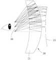
图1示出了本申请一实施例中头戴显示设备的光路原理示意图。Fig. 1 shows a schematic diagram of an optical path principle of a head-mounted display device in an embodiment of the present application.
参阅图1,本申请一实施例提供了头戴显示设备,包括显示屏10以及透镜组20,透镜组20设于显示屏10的出光侧,以将显示屏10显示的画面透射至用户的眼睛;其中,显示屏10的出光侧表面设置为曲面。Referring to FIG. 1 , an embodiment of the present application provides a head-mounted display device, including a
本申请实施例提供的头戴显示设备,通过将显示屏10的出光侧表面设置为曲面,降低了非近轴光线和近轴光线的光程差,减小像差,从而在不增加头戴显示设备体积的情况下,提升透过透镜组20输出至用户眼睛的画面的解析度,实现在保障穿戴舒适度的同时提升画面解析度。The head-mounted display device provided by the embodiment of the present application reduces the optical path difference between non-paraxial rays and paraxial rays and reduces aberrations by setting the light-emitting side surface of the
图2示出了本申请另一实施例中头戴显示设备的光路原理示意图。Fig. 2 shows a schematic diagram of an optical path principle of a head-mounted display device in another embodiment of the present application.
参阅图1和图2,在一些实施例中,显示屏10的出光侧表面构造为朝向透镜组20凸起的弧面。基于此,由于显示屏10的出光侧表面为弧面,能够降低非近轴光线和近轴光线的光程差,从而减小像差,提升画面的解析度。Referring to FIG. 1 and FIG. 2 , in some embodiments, the light-emitting side surface of the
可选地,参阅图1,透镜组20包括饼干透镜(Pancake lens)21。通过饼干透镜21对光路进行折叠,从而实现在占用空间较小的情况下,获得更多的折射界面或者反射界面,从而在减小头戴显示设备体积的同时,提升画面的解析度。透镜组20采用Pancake式折叠光路投射显示屏10显示的画面,基于Pancake技术方案的头戴显示设备,图像源进入半反半透功能的镜片之后,光线在镜片、相位延迟片以及反射式偏振片之间多次折返,最终从反射式偏振片射出,能够减小头戴显示设备的厚度,使其做得更紧凑,整体体积也会更小。在其他实施例中,也可采用多个透镜组20合的方式折叠光路。Optionally, referring to FIG. 1 , the
在一些实施例中,饼干透镜21包括依序设置的偏振件、第一偏振转换元件、部分透射部分反射元件、透镜、第二偏振转换元件和偏振分光元件。In some embodiments, the
其中,偏振件优选吸收型偏光片,比如显示行业常用的材质为聚乙烯醇(Polyvinyl alcohol,PVA)的偏光片。Wherein, the polarizer is preferably an absorbing polarizer, such as a polarizer made of polyvinyl alcohol (PVA) commonly used in the display industry.
第一偏振转换元件具体可以是四分之一波片(Quarter Wave Plate,QWP),该四分之一波片能够对入射偏振光在快慢轴分量间产生四分之一波长的延迟量,通常情况下,该四分之一波片的光轴与偏光片的透过轴的方位角为40°~50°,作为优选四分之一波片的光轴与偏光片的透过轴的方位角为44°~46°。Specifically, the first polarization conversion element may be a quarter wave plate (Quarter Wave Plate, QWP), which can produce a quarter wave retardation between the fast and slow axis components of the incident polarized light, usually Under the circumstances, the azimuth angle between the optical axis of the quarter-wave plate and the transmission axis of the polarizer is 40°~50°, as the orientation of the optical axis of the quarter-wave plate and the transmission axis of the polarizer The angle is 44°~46°.
部分透射部分反射元件可以与透镜分离设置,也可以与透镜贴合设置,作为优选,部分透射部分反射元件与透镜贴合设置。例如,部分透射部分反射元件具体可以是镀在透镜的朝向显示屏10的一侧表面的分光膜,进一步地,分光膜为半透半反膜,即50%反射50%透射。透镜带有一定屈光度,可以为平凸透镜、双凸透镜或者焦距为正的弯月透镜,为了达到更好的像差控制,优选双凸形状的透镜,即透镜朝向第一偏振转换元件的表面和透镜朝向第二偏振转换元件的表面均为凸面。当部分透射部分反射元件贴合设置在透镜朝向屏幕一侧的表面时,贴合后的结构透过率为30%~70%,例如,透过率具体可以是40%、45%、50%、55%、60%、65%。The partially transmissive and partially reflective element can be arranged separately from the lens, or can be attached to the lens. Preferably, the partially transmissive and partially reflective element is attached to the lens. For example, the partially transmissive and partially reflective element may specifically be a dichroic film coated on the surface of the lens facing the
第二偏振转换元件具体可以是四分之一波片(Quarter Wave Plate,QWP),第二偏振转换元件的材质可以与第一偏振转换元件的材质相同或相异。作为优选,第二偏振转换元件的材质可以与第一偏振转换元件的材质相同。第二偏振转换元件的光轴方向可以平行于第一偏振转换元件的光轴方向,或者垂直于第一偏振转换元件的光轴方向。Specifically, the second polarization conversion element may be a quarter wave plate (Quarter Wave Plate, QWP), and the material of the second polarization conversion element may be the same as or different from that of the first polarization conversion element. Preferably, the material of the second polarization conversion element may be the same as that of the first polarization conversion element. The direction of the optical axis of the second polarization conversion element may be parallel to the direction of the optical axis of the first polarization conversion element, or perpendicular to the direction of the optical axis of the first polarization conversion element.
当第二偏振转换元件的光轴方向平行于第一偏振转换元件的光轴方向时,偏振分光元件(Polarization Beam Splitter,PBS)的透过轴与偏振件平行;当第二偏振转换元件的光轴方向垂直于第一偏振转换元件的光轴方向时,偏振分光元件的透过轴与偏振件垂直。通过这样配置,偏振分光元件可以反射直透的偏振光,从而达到光路折叠的效果。偏振分光元件可以选择布拉格型反射偏振器件,也可以选择金属线栅型(Wire Grid)反射偏振器件。When the optical axis direction of the second polarization conversion element is parallel to the optical axis direction of the first polarization conversion element, the transmission axis of the polarization beam splitter (Polarization Beam Splitter, PBS) is parallel to the polarizer; when the light of the second polarization conversion element When the axial direction is perpendicular to the optical axis direction of the first polarization conversion element, the transmission axis of the polarization splitting element is perpendicular to the polarizer. With such a configuration, the polarization beam splitting element can reflect straight polarized light, thereby achieving the effect of optical path folding. The polarization beam splitting element may choose a Bragg type reflective polarizer, or a metal wire grid (Wire Grid) reflective polarizer.
可选的,部分透射部分反射元件与透镜之间通过光学胶进行贴合。基于此,利用光学胶无色透明、光透过率大于或等于90%、胶结强度良好、可在室温或中温下固化、固化收缩小等特点,实现部分透射部分反射元件与透镜之间的良好胶接。具体地,光学胶的材质包括有机硅胶、丙烯酸型树脂、不饱和聚酯、聚氨酯、环氧树脂中的一者或多者。Optionally, the partially transmissive and partially reflective element is bonded to the lens through optical glue. Based on this, the optical glue is colorless and transparent, the light transmittance is greater than or equal to 90%, the bonding strength is good, it can be cured at room temperature or at a medium temperature, and the curing shrinkage is small, so as to achieve a good connection between the partially transmissive and partially reflective element and the lens. glued. Specifically, the material of the optical glue includes one or more of organic silica gel, acrylic resin, unsaturated polyester, polyurethane, and epoxy resin.
在上述折叠光路结构中,主像光路的具体走向如下:显示屏10上像元的光经偏振件起偏为线偏,通过第一偏振转换元件后变为圆偏光,继续穿过第二偏振转换元件后再次变为线偏光,此时偏振方向与偏振分光元件的透过轴垂直,因而被反射,反射光到达部分透射部分反射元件时被第二次反射,同时由于反射带来的半波损失,圆偏光的手性发生翻转,导致该光线第二次穿过第二偏振转换元件后的偏振态与第一次穿过第二偏振转换元件后的偏振态正交,因此能够被偏振分光元件透过,从而形成主像。In the above-mentioned folded optical path structure, the specific direction of the main image optical path is as follows: the light of the pixel on the
进一步地,显示屏10的出光侧表面构造为朝向透镜组20凸起的弧面,透镜组20包括饼干透镜21,且显示屏10与饼干透镜21之间的间距为3mm~20mm,即显示屏10与透镜组20之间的间距较小,使得头戴显示设备的厚度能够进一步减小,从而更加符合轻量化的设计需求,提升用户的穿戴舒适度。Further, the light-emitting side surface of the
可选地,参阅图2,透镜组20包括菲涅尔透镜22。菲涅尔透镜(Fresnel lens)又称螺纹透镜,其一侧表面为光面,另一侧表面刻录了由小到大的同心圆纹路(即菲涅尔带)。菲涅尔透镜22的材质通常为聚烯烃或玻璃。可以理解的是,使用普通的凸透镜时,光在介质的交界面折射,并在凸透镜内直线传播,由于凸透镜较厚,光在凸透镜内直线传播距离较长,会使光线衰减,导致出现边角变暗、模糊的现象。因此,若能去掉直线传播的部分,只保留发生折射的曲面,便能省下大量材料,同时达到相同的聚光效果,而菲涅尔透镜22就是采用这种原理,在镜片的一侧表面设置多个同心圆纹路(即菲涅尔带),以达到凸透镜的效果。从剖面看,设有同心圆纹路的一侧表面具有多个锯齿形凹槽,中间部分是椭圆形弧线,任意相邻的两个锯齿的倾斜角度不同,但每一个锯齿均将光线集中在同一点,形成中心焦点,也就是透镜的焦点。每个锯齿可以看做一个独立的小透镜,把光线调整成平行光或聚光。这种透镜还能够消除部分球形像差。当投射光源投射平行光时,镜菲涅尔透镜22汇聚透射后能够保持图像各处亮度的一致。基于此,利用菲涅尔透镜22将显示屏10显示的画面透射至用户的眼睛,能够减小透镜组20的厚度,从而实现在减小头戴显示设备的整体体积的同时消除部分像差,即在保障用户穿戴舒适度的同时,提升画面解析度。Optionally, referring to FIG. 2 , the
进一步地,显示屏10的出光侧表面构造为朝向透镜组20凸起的弧面,透镜组20包括菲涅尔透镜22,显示屏10与透镜组20之间的间距为10mm~30mm,即显示屏10与透镜组20之间的间距较小,使得头戴显示设备的厚度能够进一步减小,从而更加符合轻量化的设计需求,提升用户的穿戴舒适度。Further, the light-emitting side surface of the
在一些实施例中,显示屏10的出光侧表面构造为朝向透镜组20凸起的弧面,且显示屏10的出光侧表面的曲率c满足条件:0<c≤0.01。基于此,能够降低非近轴光线和近轴光线的光程差,从而减小像差,提升画面的解析度。In some embodiments, the light-emitting side surface of the
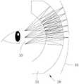
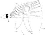
图3示出了本申请另一实施例中头戴显示设备的光路原理示意图。图4示出了本申请另一实施例中头戴显示设备的光路原理示意图。Fig. 3 shows a schematic diagram of an optical path principle of a head-mounted display device in another embodiment of the present application. Fig. 4 shows a schematic diagram of an optical path principle of a head-mounted display device in another embodiment of the present application.
参阅图3和图4,在一些实施例中,显示屏10的出光侧表面构造为背离透镜组20凹陷的弧面,从而降低非近轴光线和近轴光线的光程差,减小像差,提升画面的解析度。Referring to Fig. 3 and Fig. 4, in some embodiments, the light-emitting side surface of the
可选地,参阅图3,显示屏10的出光侧表面构造为背离透镜组20凹陷的弧面,透镜组20包括饼干透镜21,以在占用空间较小的情况下,获得更多的折射界面或者反射界面,从而在减小头戴显示设备体积的同时,提升画面的解析度。Optionally, referring to FIG. 3 , the light-emitting side surface of the
进一步地,显示屏10的出光侧表面构造为背离透镜组20凹陷的弧面,透镜组20包括饼干透镜21,显示屏10与饼干透镜21之间的间距为3mm~20mm,使得显示屏10与透镜组20之间的间距较小,头戴显示设备的厚度能够进一步减小,从而更加符合轻量化的设计需求,提升用户的穿戴舒适度。Further, the light-emitting side surface of the
在一些实施例中,显示屏10的出光侧表面构造为背离透镜组20凹陷的弧面,透镜组20包括饼干透镜21,且显示屏10的出光侧表面的曲率c满足条件:0<c≤0.02,从而降低非近轴光线和近轴光线的光程差,减小像差,提升画面的解析度。In some embodiments, the light-emitting side surface of the
参阅图4,在一些实施例中,显示屏10的出光侧表面构造为背离透镜组20凹陷的弧面,透镜组20包括沿显示屏10的出光方向依次设置的第一透镜231和第二透镜232。通过第一透镜231和第二透镜232对光路进行多次折射,使显示屏10显示的画面透射至用户的眼睛。Referring to FIG. 4 , in some embodiments, the light-emitting side surface of the
可选地,显示屏10的出光侧表面构造为背离透镜组20凹陷的弧面,透镜组20包括沿显示屏10的出光方向依次设置的第一透镜231和第二透镜232,显示屏10与第一透镜231之间的间距为3mm~20mm,从而保障头戴显示设备的体积较小,且画面解析度较高。Optionally, the light-emitting side surface of the
进一步地,显示屏10的出光侧表面构造为背离透镜组20凹陷的弧面,透镜组20包括沿显示屏10的出光方向依次设置的第一透镜231和第二透镜232,显示屏10与第一透镜231之间的间距为3mm~20mm,且显示屏10的出光侧表面的曲率c满足条件:0<c≤0.01。基于此,能够降低非近轴光线和近轴光线的光程差,减小像差,提升画面的解析度。Further, the light-emitting side surface of the
在一些实施例中,透镜组20还包括第三透镜,从而增加折射界面,进而提升画面解析度。In some embodiments, the
在一些实施例中,头戴显示设备还包括外壳,外壳具有用于与用户眼睛相对设置的侧壁30;透镜组20与侧壁30之间的间距为10mm~12mm。基于此,显示屏10显示的画面经过透镜组20透射后,传播至侧壁30上供用户的眼睛观看,使用户能够观看到解析度较高的画面。In some embodiments, the head-mounted display device further includes a casing, and the casing has a
当图像从投射仪投射、反射或者以其他方式导向到用户的眼睛中时,图像可以视觉上占据的显示空间称为眼盒(Eyebox),并且可具有称为眼盒尺寸的尺寸。AR体验中的用户可看到跨越其整个视场的眼盒中的虚拟对象,或者眼盒可以更小,使得眼盒覆盖用户的视场的一部分。用户可观看的虚拟对象可包括对数字屏幕显示器上示出的对象常见的图像属性,包括分辨率、亮度、颜色和其他可见特征。When an image is projected, reflected, or otherwise directed into a user's eye from a projector, the display space that the image may visually occupy is called the eyebox, and may have a dimension called the eyebox size. A user in an AR experience may see virtual objects in an eye box that spans their entire field of view, or the eye box may be smaller such that the eye box covers a portion of the user's field of view. The virtual objects viewable by the user may include image attributes common to objects shown on digital screen displays, including resolution, brightness, color, and other visible characteristics.
眼盒的大小决定眼睛可以在最佳位置向上、下、左、右移动而不影响图像显示质量的距离。以VR光学成像系统为例,若接收眼与输出区域的中心对齐,则能够获得清晰度高、成像质量佳的图像。而当眼睛朝向侧面或者上下移动时,在每个方向上的某点处,成像质量将会变差,直至出现图像扭曲、显色错误、甚至不显示内容等情况。The size of the eye box determines how far the eye can move up, down, left, and right in the optimal position without affecting the image display quality. Taking the VR optical imaging system as an example, if the receiving eye is aligned with the center of the output area, images with high definition and good imaging quality can be obtained. And when the eye is moved sideways or up and down, at some point in each direction, the image quality will degrade until the image is distorted, the color is rendered incorrectly, or even the content is not displayed.
在本申请一实施例中,头戴显示设备的眼盒的尺寸为8mm×8mm。基于此,用户能够获得较佳的视觉体验。In an embodiment of the present application, the size of the eye box of the head-mounted display device is 8mm×8mm. Based on this, users can obtain a better visual experience.
在一些实施例中,头戴显示设备包括外壳、显示屏、透镜组及控制组件,透镜组、显示屏及控制组件设于外壳内。控制组件的结构及原理可以参考相关技术中头戴显示设备的控制组件的结构及原理,例如,在一具体实施例中,控制组件具体可以是相关技术中头戴显示设备的控制主板,该控制主板能够处理电子信号并发送控制指令,在另一具体实施例中,控制组件也可以是与头戴显示设备相连接的主机的核心处理器,本申请对此并不限制,能够处理信号发送指令即可。In some embodiments, the head-mounted display device includes a casing, a display screen, a lens group and a control component, and the lens group, the display screen and the control component are arranged in the casing. The structure and principle of the control component can refer to the structure and principle of the control component of the head-mounted display device in the related art. For example, in a specific embodiment, the control component can specifically be the control board of the head-mounted display device in the related art. The main board can process electronic signals and send control commands. In another specific embodiment, the control component can also be the core processor of the host connected to the head-mounted display device. This application is not limited to this, and can process signal sending commands That's it.
以上所述实施例的各技术特征可以进行任意的组合,为使描述简洁,未对上述实施例中的各个技术特征所有可能的组合都进行描述,然而,只要这些技术特征的组合不存在矛盾,都应当认为是本说明书记载的范围。The technical features of the above-mentioned embodiments can be combined arbitrarily. To make the description concise, all possible combinations of the technical features in the above-mentioned embodiments are not described. However, as long as there is no contradiction in the combination of these technical features, should be considered as within the scope of this specification.
以上所述实施例仅表达了本申请的几种实施方式,其描述较为具体和详细,但并不能因此而理解为对申请专利范围的限制。应当指出的是,对于本领域的普通技术人员来说,在不脱离本申请构思的前提下,还可以做出若干变形和改进,这些都属于本申请的保护范围。因此,本申请专利的保护范围应以所附权利要求为准。The above-mentioned embodiments only express several implementation modes of the present application, and the description thereof is relatively specific and detailed, but should not be construed as limiting the scope of the patent application. It should be noted that those skilled in the art can make several modifications and improvements without departing from the concept of the present application, and these all belong to the protection scope of the present application. Therefore, the scope of protection of the patent application should be based on the appended claims.
Claims (10)
Priority Applications (1)
| Application Number | Priority Date | Filing Date | Title |
|---|---|---|---|
| CN202211077659.8ACN115373149A (en) | 2022-09-05 | 2022-09-05 | head mounted display device |
Applications Claiming Priority (1)
| Application Number | Priority Date | Filing Date | Title |
|---|---|---|---|
| CN202211077659.8ACN115373149A (en) | 2022-09-05 | 2022-09-05 | head mounted display device |
Publications (1)
| Publication Number | Publication Date |
|---|---|
| CN115373149Atrue CN115373149A (en) | 2022-11-22 |
Family
ID=84070200
Family Applications (1)
| Application Number | Title | Priority Date | Filing Date |
|---|---|---|---|
| CN202211077659.8APendingCN115373149A (en) | 2022-09-05 | 2022-09-05 | head mounted display device |
Country Status (1)
| Country | Link |
|---|---|
| CN (1) | CN115373149A (en) |
Cited By (2)
| Publication number | Priority date | Publication date | Assignee | Title |
|---|---|---|---|---|
| CN116068773A (en)* | 2023-03-06 | 2023-05-05 | 惠科股份有限公司 | Head-mounted display device and preparation method thereof |
| WO2024221523A1 (en)* | 2023-04-28 | 2024-10-31 | 武汉华星光电技术有限公司 | Display device |
Citations (13)
| Publication number | Priority date | Publication date | Assignee | Title |
|---|---|---|---|---|
| CN101299078A (en)* | 2007-04-30 | 2008-11-05 | 黄峰彪 | Method for manufacturing complete view angle display apparatus |
| CN106324838A (en)* | 2016-09-30 | 2017-01-11 | 中国科学院长春光学精密机械与物理研究所 | Virtual reality equipment and virtual reality system |
| CN106371214A (en)* | 2016-11-23 | 2017-02-01 | 杭州映墨科技有限公司 | Distortion and dispersion reducing optical structure for virtual reality (VR) helmet |
| CN206348530U (en)* | 2016-12-26 | 2017-07-21 | 云谷(固安)科技有限公司 | Virtual reality shows structure and wearable virtual reality display device |
| CN109923461A (en)* | 2016-10-31 | 2019-06-21 | 康宁股份有限公司 | The wide visual field individual display of single centre |
| WO2019154430A1 (en)* | 2018-02-12 | 2019-08-15 | 杭州太若科技有限公司 | Wearable ar system, ar display device, and projection source module thereof |
| CN111868603A (en)* | 2018-04-25 | 2020-10-30 | 三星电子株式会社 | Spliced triplet lens for wide field of view |
| CN112305762A (en)* | 2020-10-26 | 2021-02-02 | 深圳惠牛科技有限公司 | Display optical system for reducing ghost and head-mounted display device |
| CN112305764A (en)* | 2020-10-26 | 2021-02-02 | 深圳惠牛科技有限公司 | Display optical system for correcting chromatic aberration and head-mounted display device |
| CN112799232A (en)* | 2021-03-19 | 2021-05-14 | 光感(上海)科技有限公司 | A portable short-focus near-eye display system |
| CN213715608U (en)* | 2020-10-26 | 2021-07-16 | 深圳惠牛科技有限公司 | Display optical system for reducing ghost and head-mounted display device |
| CN213780542U (en)* | 2020-10-26 | 2021-07-23 | 深圳惠牛科技有限公司 | Display optical system for correcting chromatic aberration and head-mounted display device |
| CN114415380A (en)* | 2022-03-15 | 2022-04-29 | 安徽熙泰智能科技有限公司 | Near-to-eye display glasses |
- 2022
- 2022-09-05CNCN202211077659.8Apatent/CN115373149A/enactivePending
Patent Citations (14)
| Publication number | Priority date | Publication date | Assignee | Title |
|---|---|---|---|---|
| CN101299078A (en)* | 2007-04-30 | 2008-11-05 | 黄峰彪 | Method for manufacturing complete view angle display apparatus |
| CN106324838A (en)* | 2016-09-30 | 2017-01-11 | 中国科学院长春光学精密机械与物理研究所 | Virtual reality equipment and virtual reality system |
| CN109923461A (en)* | 2016-10-31 | 2019-06-21 | 康宁股份有限公司 | The wide visual field individual display of single centre |
| CN106371214A (en)* | 2016-11-23 | 2017-02-01 | 杭州映墨科技有限公司 | Distortion and dispersion reducing optical structure for virtual reality (VR) helmet |
| CN206348530U (en)* | 2016-12-26 | 2017-07-21 | 云谷(固安)科技有限公司 | Virtual reality shows structure and wearable virtual reality display device |
| CN110537133A (en)* | 2018-02-12 | 2019-12-03 | 优奈柯恩(北京)科技有限公司 | Wearable AR system, AR show equipment and its projection source mould group |
| WO2019154430A1 (en)* | 2018-02-12 | 2019-08-15 | 杭州太若科技有限公司 | Wearable ar system, ar display device, and projection source module thereof |
| CN111868603A (en)* | 2018-04-25 | 2020-10-30 | 三星电子株式会社 | Spliced triplet lens for wide field of view |
| CN112305762A (en)* | 2020-10-26 | 2021-02-02 | 深圳惠牛科技有限公司 | Display optical system for reducing ghost and head-mounted display device |
| CN112305764A (en)* | 2020-10-26 | 2021-02-02 | 深圳惠牛科技有限公司 | Display optical system for correcting chromatic aberration and head-mounted display device |
| CN213715608U (en)* | 2020-10-26 | 2021-07-16 | 深圳惠牛科技有限公司 | Display optical system for reducing ghost and head-mounted display device |
| CN213780542U (en)* | 2020-10-26 | 2021-07-23 | 深圳惠牛科技有限公司 | Display optical system for correcting chromatic aberration and head-mounted display device |
| CN112799232A (en)* | 2021-03-19 | 2021-05-14 | 光感(上海)科技有限公司 | A portable short-focus near-eye display system |
| CN114415380A (en)* | 2022-03-15 | 2022-04-29 | 安徽熙泰智能科技有限公司 | Near-to-eye display glasses |
Cited By (2)
| Publication number | Priority date | Publication date | Assignee | Title |
|---|---|---|---|---|
| CN116068773A (en)* | 2023-03-06 | 2023-05-05 | 惠科股份有限公司 | Head-mounted display device and preparation method thereof |
| WO2024221523A1 (en)* | 2023-04-28 | 2024-10-31 | 武汉华星光电技术有限公司 | Display device |
Similar Documents
| Publication | Publication Date | Title |
|---|---|---|
| JP3994896B2 (en) | Video display device | |
| CN113219665B (en) | Optical lens group, optical system and head-mounted display device | |
| CN1867855B (en) | Optical Devices for Substrate Waveguiding | |
| WO2020095311A1 (en) | Light-guide display with reflector | |
| JP2020526780A (en) | Small near-eye optical system including refracting beam-separated convex lens | |
| US20240302658A1 (en) | Optical module and head mount display | |
| CN115561910B (en) | Near-to-eye display module and head-mounted display device | |
| HK1204079A1 (en) | Substrate-guided optical device | |
| CN104614858A (en) | Saw tooth structure plane waveguide visual optical display device for enhancing reality | |
| US20240264445A1 (en) | Optical module and head mount display | |
| JP2024502803A (en) | Optical modules and electronic devices | |
| CN115373149A (en) | head mounted display device | |
| CN114967135B (en) | Ultra-short throw eyepiece system | |
| CN114859560A (en) | Optical modules and head-mounted display devices | |
| WO2023071032A1 (en) | Short-focus folding optical system and virtual reality display device | |
| CN117075337A (en) | Optical module and head-mounted display device | |
| CN117031747A (en) | Optical module and head-mounted display device | |
| CN112162382B (en) | Lenses, projection optics and near-eye display systems | |
| CN118068563A (en) | Optical system and display device | |
| KR102524150B1 (en) | Apparatus and method for providing a large-screen direct-view augmented reality image using a transparent display | |
| CN114624889A (en) | Enhanced display type near-to-eye display projection optical device | |
| JP2001343608A (en) | Image display device and image display system | |
| CN118963051A (en) | Light source collimation module, projection optical machine and electronic equipment | |
| WO2025036219A1 (en) | Optical module and head-mounted display device | |
| WO2025060719A1 (en) | Near-eye optical system and head-worn display device |
Legal Events
| Date | Code | Title | Description |
|---|---|---|---|
| PB01 | Publication | ||
| PB01 | Publication | ||
| SE01 | Entry into force of request for substantive examination | ||
| SE01 | Entry into force of request for substantive examination | ||
| TA01 | Transfer of patent application right | Effective date of registration:20240109 Address after:518109, Building E4, 101, Foxconn Industrial Park, No. 2 East Ring 2nd Road, Fukang Community, Longhua Street, Longhua District, Shenzhen City, Guangdong Province (formerly Building 1, 1st Floor, G2 District), H3, H1, and H7 factories in K2 District, North Shenchao Optoelectronic Technology Park, Minqing Road, Guangdong Province Applicant after:INTERFACE OPTOELECTRONICS (SHENZHEN) Co.,Ltd. Applicant after:Interface Technology (Chengdu) Co., Ltd. Applicant after:GENERAL INTERFACE SOLUTION Ltd. Address before:No.689 Hezuo Road, West District, high tech Zone, Chengdu City, Sichuan Province Applicant before:Interface Technology (Chengdu) Co., Ltd. Applicant before:INTERFACE OPTOELECTRONICS (SHENZHEN) Co.,Ltd. Applicant before:Yicheng Photoelectric (Wuxi) Co.,Ltd. Applicant before:GENERAL INTERFACE SOLUTION Ltd. | |
| TA01 | Transfer of patent application right | ||
| RJ01 | Rejection of invention patent application after publication | Application publication date:20221122 |