Movatterモバイル変換


[0]ホーム

URL:


CN115373119B - Optical lens, camera module and electronic equipment - Google Patents

Optical lens, camera module and electronic equipment
Download PDF

Info

Publication number
CN115373119B
CN115373119BCN202211317687.2ACN202211317687ACN115373119BCN 115373119 BCN115373119 BCN 115373119BCN 202211317687 ACN202211317687 ACN 202211317687ACN 115373119 BCN115373119 BCN 115373119B
Authority
CN
China
Prior art keywords
lens
optical
optical axis
optical lens
image
Prior art date
Legal status (The legal status is an assumption and is not a legal conclusion. Google has not performed a legal analysis and makes no representation as to the accuracy of the status listed.)
Active
Application number
CN202211317687.2A
Other languages
Chinese (zh)
Other versions
CN115373119A (en
Inventor
张文燕
徐标
李翔宇
Current Assignee (The listed assignees may be inaccurate. Google has not performed a legal analysis and makes no representation or warranty as to the accuracy of the list.)
Jiangxi Oufei Optics Co ltd
Original Assignee
Jiangxi Jingchao Optical Co Ltd
Priority date (The priority date is an assumption and is not a legal conclusion. Google has not performed a legal analysis and makes no representation as to the accuracy of the date listed.)
Filing date
Publication date
Application filed by Jiangxi Jingchao Optical Co LtdfiledCriticalJiangxi Jingchao Optical Co Ltd
Priority to CN202211317687.2ApriorityCriticalpatent/CN115373119B/en
Publication of CN115373119ApublicationCriticalpatent/CN115373119A/en
Application grantedgrantedCritical
Publication of CN115373119BpublicationCriticalpatent/CN115373119B/en
Activelegal-statusCriticalCurrent
Anticipated expirationlegal-statusCritical

Links

Images

Classifications

Landscapes

Abstract

The invention discloses an optical lens, a camera module and an electronic device, wherein the optical lens comprises five lenses with refractive power, the five lenses are a first lens, a second lens, a third lens, a fourth lens and a fifth lens from an object side to an image side along an optical axis in sequence, the refractive power of the first lens to the fifth lens is positive, negative and positive in sequence, the object side surface and the image side surface of the first lens and the fifth lens at a paraxial region are convex surfaces, the object side surface and the image side surface of the second lens at the paraxial region are respectively convex surfaces and concave surfaces, the object side surface of the fourth lens at the paraxial region is a concave surface, and the optical lens meets the following relational expressions: -6.5 sR10/f < -0.1; wherein, R10 is a curvature radius of the image-side surface of the fifth lens element at the optical axis, and f is a focal length of the optical lens assembly. The optical lens, the camera module and the electronic equipment provided by the invention can realize the light, thin and miniaturized design of the optical lens and improve the imaging quality of the optical lens.

Description

Translated fromChinese
光学镜头、摄像模组及电子设备Optical lens, camera module and electronic equipment

技术领域technical field

本发明涉及光学成像技术领域,尤其涉及一种光学镜头、摄像模组及电子设备。The invention relates to the technical field of optical imaging, in particular to an optical lens, a camera module and electronic equipment.

背景技术Background technique

近年来,随着摄像技术的发展,人们对光学镜头的成像品质要求越来越高,同时轻薄小型化的结构特点也逐渐成为光学镜头的发展趋势。相关技术中,在满足光学镜头轻薄小型化的设计趋势下,难以同时满足人们对光学镜头的高清成像要求。In recent years, with the development of camera technology, people have higher and higher requirements for the imaging quality of optical lenses. At the same time, the structural characteristics of lightness, thinness and miniaturization have gradually become the development trend of optical lenses. In related technologies, it is difficult to meet people's high-definition imaging requirements for optical lenses while satisfying the design trend of optical lenses being thin, light and miniaturized.

发明内容Contents of the invention

本发明实施例公开了一种光学镜头、摄像模组及电子设备,能够在实现光学镜头的轻薄、小型化设计的同时,提高光学镜头的成像品质。The embodiment of the invention discloses an optical lens, a camera module and electronic equipment, which can improve the imaging quality of the optical lens while realizing the light, thin and miniaturized design of the optical lens.

为了实现上述目的,第一方面,本发明公开了一种光学镜头,所述光学镜头共有五片具有屈折力的透镜,五片所述透镜沿光轴从物侧至像侧依次为第一透镜、第二透镜、第三透镜、第四透镜和第五透镜;In order to achieve the above object, in the first aspect, the present invention discloses an optical lens, the optical lens has five lenses with refractive power, and the five lenses are the first lens in sequence from the object side to the image side along the optical axis , the second lens, the third lens, the fourth lens and the fifth lens;

所述第一透镜具有正屈折力,所述第一透镜的物侧面于近光轴处为凸面,所述第一透镜的像侧面于近光轴处为凸面;The first lens has positive refractive power, the object side of the first lens is convex at the near optical axis, and the image side of the first lens is convex at the near optical axis;

所述第二透镜具有负屈折力,所述第二透镜的物侧面于近光轴处为凸面,所述第二透镜的像侧面于近光轴处为凹面;The second lens has a negative refractive power, the object side of the second lens is convex at the near optical axis, and the image side of the second lens is concave at the near optical axis;

所述第三透镜具有负屈折力;The third lens has a negative refractive power;

所述第四透镜具有负屈折力,所述第四透镜的物侧面于近光轴处为凹面;The fourth lens has a negative refractive power, and the object side of the fourth lens is concave at the near optical axis;

所述第五透镜具有正屈折力,所述第五透镜的物侧面于近光轴处为凸面,所述第五透镜的像侧面于近光轴处为凸面;The fifth lens has positive refractive power, the object side of the fifth lens is convex at the near optical axis, and the image side of the fifth lens is convex at the near optical axis;

所述光学镜头满足以下关系式:-6.5<R10/f<-0.1;The optical lens satisfies the following relationship: -6.5<R10/f<-0.1;

其中,R10为所述第五透镜的像侧面于所述光轴处的曲率半径,f为所述光学镜头的焦距。本申请提供的光学镜头中,第一透镜具有正屈折力,起到汇聚光线的作用,有利于大角度的入射光线进入光学系统,使光学系统具有较大的视场角,以满足光学系统对拍摄范围的需求;且第一透镜采用于光轴处双凸的面型,可加强第一透镜的正屈折力,有利于缩短光学系统的总长;第二透镜具有负屈折力,第二透镜的物侧面于近光轴处为凸面,第二透镜的像侧面于近光轴处为凹面,有利于矫正光学镜头的畸变,提高成像质量;第三透镜具有负屈折力,可抵消第一透镜或者第二透镜产生的球差以及彗差等像差;第四透镜具备负屈折力,且第四透镜的物侧面于近光轴处为凹面,有利于校正入射光线经过前述透镜所产生的畸变、像散及场曲,提高成像质量;第五透镜具有正屈折力,配合第五透镜于近光轴处的凸凸面型,有利于平衡第四透镜的像差,进一步提升光学镜头的成像质量,同时也有利于进一步收缩光线,从而有利于缩短光学镜头的总长。Wherein, R10 is the radius of curvature of the image side of the fifth lens at the optical axis, and f is the focal length of the optical lens. In the optical lens provided by the present application, the first lens has a positive refractive power and plays the role of converging light, which is conducive to the incident light with a large angle entering the optical system, so that the optical system has a larger field of view to meet the requirements of the optical system. The requirements of the shooting range; and the first lens adopts a biconvex surface at the optical axis, which can strengthen the positive refractive power of the first lens and help shorten the total length of the optical system; the second lens has negative refractive power, and the second lens has a negative refractive power. The object side is convex at the near optical axis, and the image side of the second lens is concave at the near optical axis, which is beneficial to correct the distortion of the optical lens and improve the imaging quality; the third lens has negative refractive power, which can offset the first lens or Aberrations such as spherical aberration and coma generated by the second lens; the fourth lens has negative refractive power, and the object side of the fourth lens is concave at the near optical axis, which is beneficial to correct the distortion generated by the incident light passing through the aforementioned lens, Astigmatism and field curvature improve imaging quality; the fifth lens has positive refractive power, and the convex-convex shape of the fifth lens at the near optical axis is beneficial to balance the aberration of the fourth lens and further improve the imaging quality of the optical lens. At the same time, it is also beneficial to further shrink the light, thereby helping to shorten the total length of the optical lens.

此外,光学镜头满足关系式:-6.5<R10/f<-0.1。满足上述关系式时,能够将第五透镜的像侧面于光轴处的曲率半径、光学镜头的焦距控制在合理的范围内,从而有利于矫正光学镜头的像散、场曲和畸变,压缩光学镜头的光学总长,实现光学镜头轻薄小型化的设计要求。低于上述关系式的下限时,第五透镜的像侧面于光轴处的曲率半径过大,导致第五透镜的面型过于平缓,难以充分地校正像散、场曲和畸变;超过上述关系式的上限时,第五透镜的像侧面于光轴处的曲率半径过小,导致第五透镜的面型弯曲度过大,增加了第五透镜的敏感度,不利于第五透镜的工程制造。In addition, the optical lens satisfies the relationship: -6.5<R10/f<-0.1. When the above relationship is satisfied, the radius of curvature of the image side of the fifth lens at the optical axis and the focal length of the optical lens can be controlled within a reasonable range, which is beneficial to correct the astigmatism, field curvature and distortion of the optical lens, and compress the optical lens. The total optical length of the lens meets the design requirements for light, thin and miniaturized optical lenses. Below the lower limit of the above relationship, the radius of curvature of the image side of the fifth lens at the optical axis is too large, causing the surface of the fifth lens to be too gentle, and it is difficult to fully correct astigmatism, curvature of field and distortion; exceeding the above relationship When the upper limit of the formula is reached, the radius of curvature of the image side of the fifth lens at the optical axis is too small, causing the surface curvature of the fifth lens to be too large, which increases the sensitivity of the fifth lens, which is not conducive to the engineering manufacture of the fifth lens .

第二方面,本发明公开了一种摄像模组,所述摄像模组包括感光芯片和如上述第一方面所述的光学镜头,所述感光芯片设置于所述光学镜头的像侧。具有所述光学镜头的摄像模组能够在降低光学镜头光学总长,实现光学镜头的轻薄、小型化设计的同时,校正光学镜头的畸变、像散及场曲等像差,提高光学镜头的成像品质。In a second aspect, the present invention discloses a camera module. The camera module includes a photosensitive chip and the optical lens as described in the first aspect above, and the photosensitive chip is arranged on the image side of the optical lens. The camera module with the optical lens can reduce the total optical length of the optical lens and realize the light and thin design of the optical lens while correcting aberrations such as distortion, astigmatism and curvature of field of the optical lens and improving the imaging quality of the optical lens .

第三方面,本发明还公开了一种电子设备,所述电子设备包括壳体和如上述第二方面所述的摄像模组,所述摄像模组设于所述壳体。具有所述摄像模组的电子设备,能够在降低光学镜头光学总长,实现光学镜头的轻薄、小型化设计的同时,校正光学镜头的畸变、像散及场曲等像差,提高光学镜头的成像品质。In a third aspect, the present invention also discloses an electronic device, the electronic device includes a casing and the camera module as described in the second aspect above, and the camera module is arranged in the casing. The electronic device with the camera module can correct the distortion, astigmatism, field curvature and other aberrations of the optical lens while reducing the total optical length of the optical lens and realize the light and thin, miniaturized design of the optical lens, so as to improve the imaging performance of the optical lens. quality.

与现有技术相比,本发明的有益效果在于:Compared with prior art, the beneficial effect of the present invention is:

本发明实施例提供的一种光学镜头、摄像模组及电子设备,所述光学镜头采用五片透镜,通过对五片透镜的屈折力、面型进行设计,同时使得光学镜头满足关系式:-6.5<R10/f<-0.1,以将第五透镜的像侧面于光轴处的曲率半径、光学镜头的焦距控制在合理的范围内,从而有利于矫正光学镜头的像散、场曲和畸变,压缩光学镜头的光学总长,实现光学镜头轻薄小型化的设计要求。An optical lens, camera module and electronic equipment provided by the embodiments of the present invention, the optical lens adopts five lenses, and by designing the refractive power and surface shape of the five lenses, the optical lens satisfies the relational expression:- 6.5<R10/f<-0.1, to control the radius of curvature of the image side of the fifth lens at the optical axis and the focal length of the optical lens within a reasonable range, which is beneficial to correct the astigmatism, field curvature and distortion of the optical lens , to compress the total optical length of the optical lens, and realize the design requirements of thinner and smaller optical lens.

附图说明Description of drawings

为了更清楚地说明本发明实施例中的技术方案,下面将对实施例中所需要使用的附图作简单地介绍,显而易见地,下面描述中的附图仅仅是本发明的一些实施例,对于本领域普通技术人员来讲,在不付出创造性劳动的前提下,还可以根据这些附图获得其他的附图。In order to more clearly illustrate the technical solutions in the embodiments of the present invention, the following will briefly introduce the accompanying drawings that need to be used in the embodiments. Obviously, the accompanying drawings in the following description are only some embodiments of the present invention. For Those of ordinary skill in the art can also obtain other drawings based on these drawings without making creative efforts.

图1是本申请第一实施例公开的光学镜头的结构示意图;FIG. 1 is a schematic structural view of the optical lens disclosed in the first embodiment of the present application;

图2是本申请第一实施例公开的光学镜头的纵向球差图(mm)、像散曲线图(mm)及畸变曲线图(%);Fig. 2 is the longitudinal spherical aberration diagram (mm), astigmatism curve diagram (mm) and distortion curve diagram (%) of the optical lens disclosed in the first embodiment of the present application;

图3是本申请第二实施例公开的光学镜头的结构示意图;FIG. 3 is a schematic structural view of the optical lens disclosed in the second embodiment of the present application;

图4是本申请第二实施例公开的光学镜头的纵向球差图(mm)、像散曲线图(mm)和畸变曲线图(%);Fig. 4 is the longitudinal spherical aberration diagram (mm), astigmatism curve diagram (mm) and distortion curve diagram (%) of the optical lens disclosed in the second embodiment of the present application;

图5是本申请第三实施例公开的光学镜头的结构示意图;Fig. 5 is a schematic structural diagram of the optical lens disclosed in the third embodiment of the present application;

图6是本申请第三实施例公开的光学镜头的纵向球差图(mm)、像散曲线图(mm)和畸变曲线图(%);Fig. 6 is the longitudinal spherical aberration diagram (mm), astigmatism curve diagram (mm) and distortion curve diagram (%) of the optical lens disclosed in the third embodiment of the present application;

图7是本申请第四实施例公开的光学镜头的结构示意图;Fig. 7 is a schematic structural view of the optical lens disclosed in the fourth embodiment of the present application;

图8是本申请第四实施例公开的光学镜头的纵向球差图(mm)、像散曲线图(mm)和畸变曲线图(%);Fig. 8 is the longitudinal spherical aberration diagram (mm), astigmatism curve diagram (mm) and distortion curve diagram (%) of the optical lens disclosed in the fourth embodiment of the present application;

图9是本申请第五实施例公开的光学镜头的结构示意图;FIG. 9 is a schematic structural view of the optical lens disclosed in the fifth embodiment of the present application;

图10是本申请第五实施例公开的光学镜头的纵向球差图(mm)、像散曲线图(mm)和畸变曲线图(%);Fig. 10 is the longitudinal spherical aberration diagram (mm), astigmatism curve diagram (mm) and distortion curve diagram (%) of the optical lens disclosed in the fifth embodiment of the present application;

图11是本申请第六实施例公开的光学镜头的结构示意图;Fig. 11 is a schematic structural view of the optical lens disclosed in the sixth embodiment of the present application;

图12是本申请第六实施例公开的光学镜头的纵向球差图(mm)、像散曲线图(mm)和畸变曲线图(%);Fig. 12 is the longitudinal spherical aberration diagram (mm), astigmatism curve diagram (mm) and distortion curve diagram (%) of the optical lens disclosed in the sixth embodiment of the present application;

图13是本申请第七实施例公开的光学镜头的结构示意图;Fig. 13 is a schematic structural view of the optical lens disclosed in the seventh embodiment of the present application;

图14是本申请第七实施例公开的光学镜头的纵向球差图(mm)、像散曲线图(mm)和畸变曲线图(%);Fig. 14 is the longitudinal spherical aberration diagram (mm), astigmatism curve diagram (mm) and distortion curve diagram (%) of the optical lens disclosed in the seventh embodiment of the present application;

图15是本申请公开的摄像模组的结构示意图;Fig. 15 is a schematic structural view of the camera module disclosed in the present application;

图16是本申请公开的电子设备的结构示意图。FIG. 16 is a schematic structural diagram of an electronic device disclosed in the present application.

具体实施方式Detailed ways

下面将结合本发明实施例中的附图,对本发明实施例中的技术方案进行清楚、完整地描述,显然,所描述的实施例仅是本发明一部分实施例,而不是全部的实施例。基于本发明中的实施例,本领域普通技术人员在没有做出创造性劳动前提下所获得的所有其他实施例,都属于本发明保护的范围。The following will clearly and completely describe the technical solutions in the embodiments of the present invention with reference to the accompanying drawings in the embodiments of the present invention. Obviously, the described embodiments are only some of the embodiments of the present invention, not all of them. Based on the embodiments of the present invention, all other embodiments obtained by persons of ordinary skill in the art without making creative efforts belong to the protection scope of the present invention.

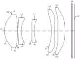
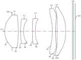
请参阅图1,根据本申请的第一方面,本申请公开了一种光学镜头100,该光学镜头100共有五片具有屈折力的透镜,五片透镜沿光轴O从物侧至像侧依次为第一透镜L1、第二透镜L2、第三透镜L3、第四透镜L4和第五透镜L5。成像时,光线从第一透镜L1的物侧依次进入第一透镜L1、第二透镜L2、第三透镜L3、第四透镜L4和第五透镜L5并最终成像于光学镜头100的成像面101上。Please refer to Fig. 1, according to the first aspect of the present application, the present application discloses anoptical lens 100, theoptical lens 100 has five lenses with refractive power in total, and the five lenses are in sequence from the object side to the image side along the optical axis O They are the first lens L1, the second lens L2, the third lens L3, the fourth lens L4 and the fifth lens L5. When imaging, the light enters the first lens L1, the second lens L2, the third lens L3, the fourth lens L4 and the fifth lens L5 from the object side of the first lens L1 in sequence, and finally forms an image on theimaging surface 101 of theoptical lens 100 .

其中,第一透镜L1具有正屈折力,第二透镜L2具有负屈折力,第三透镜L3具有负屈折力,第四透镜L4具有负屈折力,第五透镜L5具有正屈折力。第一透镜L1的物侧面S1于近光轴O处可为凸面,第一透镜L1的像侧面S2于近光轴O处可为凸面,第二透镜L2的物侧面S3于近光轴O处可为凸面,第二透镜L2的像侧面S4于近光轴O处可为凹面,第三透镜L3的物侧面S5于近光轴O处可为凸面或凹面,第三透镜L3的像侧面S6于近光轴O处可为凸面或凹面,第四透镜L4的物侧面S7于近光轴O处可为凹面,第四透镜L4的像侧面S8于近光轴O处可为凸面或凹面,第五透镜L5的物侧面S9于近光轴O处可为凸面,第五透镜L5的像侧面S10于近光轴O处可为凸面。Wherein, the first lens L1 has positive refractive power, the second lens L2 has negative refractive power, the third lens L3 has negative refractive power, the fourth lens L4 has negative refractive power, and the fifth lens L5 has positive refractive power. The object side S1 of the first lens L1 can be convex at the near optical axis O, the image side S2 of the first lens L1 can be convex at the near optical axis O, and the object side S3 of the second lens L2 can be convex at the near optical axis O It can be convex, the image side S4 of the second lens L2 can be concave at the near optical axis O, the object side S5 of the third lens L3 can be convex or concave at the near optical axis O, and the image side S6 of the third lens L3 It can be convex or concave at the near optical axis O, the object side S7 of the fourth lens L4 can be concave at the near optical axis O, and the image side S8 of the fourth lens L4 can be convex or concave at the near optical axis O, The object side S9 of the fifth lens L5 can be convex at the near optical axis O, and the image side S10 of the fifth lens L5 can be convex at the near optical axis O.

本申请提供的光学镜头100中,第一透镜L1具有正屈折力,起到汇聚光线的作用,有利于大角度的入射光线进入光学系统,使光学系统具有较大的视场角,以满足光学系统对拍摄范围的需求;且第一透镜L1采用于光轴O处双凸的面型,可加强第一透镜L1的正屈折力,有利于缩短光学系统的总长;第二透镜L2具有负屈折力,第二透镜L2的物侧面S3于近光轴O处为凸面,第二透镜L2的像侧面S4于近光轴O处为凹面,有利于矫正光学镜头100的畸变,提高成像质量;第三透镜L3具有负屈折力,可抵消第一透镜L1或者第二透镜L2产生的球差以及彗差等像差;第四透镜L4具备负屈折力,且第四透镜L4的物侧面S7于近光轴O处为凹面,有利于校正入射光线经过前述透镜所产生的畸变、像散及场曲,提高成像质量;第五透镜L5具有正屈折力,配合第五透镜L5于近光轴O处的凸凸面型,有利于平衡第四透镜L4的像差,进一步提升光学镜头100的成像质量,同时也有利于进一步收缩光线,从而有利于缩短光学镜头100的总长。In theoptical lens 100 provided by the present application, the first lens L1 has a positive refractive power, which plays the role of converging light, which is beneficial for incident light with a large angle to enter the optical system, so that the optical system has a larger viewing angle to meet the requirements of the optical system. The requirements of the system for the shooting range; and the first lens L1 adopts a biconvex surface at the optical axis O, which can strengthen the positive refractive power of the first lens L1 and help shorten the total length of the optical system; the second lens L2 has negative refractive power The object side S3 of the second lens L2 is a convex surface at the near optical axis O, and the image side S4 of the second lens L2 is concave at the near optical axis O, which is conducive to correcting the distortion of theoptical lens 100 and improving the imaging quality; The third lens L3 has a negative refractive power, which can offset aberrations such as spherical aberration and coma produced by the first lens L1 or the second lens L2; the fourth lens L4 has a negative refractive power, and the object side S7 of the fourth lens L4 is closer to the near The optical axis O is a concave surface, which is beneficial to correct the distortion, astigmatism and field curvature caused by the incident light passing through the aforementioned lens, and improve the imaging quality; the fifth lens L5 has positive refractive power, and cooperates with the fifth lens L5 at the near optical axis O The convex-convex shape is beneficial to balance the aberration of the fourth lens L4, further improves the imaging quality of theoptical lens 100, and is also conducive to further shrinking the light, so as to shorten the total length of theoptical lens 100.

一些实施例中,光学镜头100可应用于手机、平板、行车记录仪、安防监控器等电子设备,则第一透镜L1、第二透镜L2、第三透镜L3、第四透镜L4和第五透镜L5的材质可选用塑料,从而使得光学镜头100具有良好的光学效果的同时,使得光学镜头具有良好的轻便性。此外,塑料材质更易于透镜的加工,从而可降低光学镜头的加工成本。In some embodiments, theoptical lens 100 can be applied to electronic devices such as mobile phones, tablets, driving recorders, security monitors, etc., then the first lens L1, the second lens L2, the third lens L3, the fourth lens L4 and the fifth lens The material of the L5 can be made of plastic, so that theoptical lens 100 has good optical effects and at the same time makes the optical lens have good portability. In addition, the plastic material is easier to process the lens, thereby reducing the processing cost of the optical lens.

在一些实施例中,光学镜头100中透镜的材质也可以为玻璃,具有玻璃材质的透镜能够耐受较高或较低的温度且具有优良的光学效果及较佳的稳定性。In some embodiments, the material of the lens in theoptical lens 100 can also be glass, and the lens made of glass can withstand higher or lower temperature and has excellent optical effect and better stability.

在一些实施例中,光学镜头100中还可设置至少两种不同材质的透镜,例如可采用玻璃透镜及塑料透镜相结合的设计,但具体配置关系可根据实际需求而确定,此处不加以穷举。In some embodiments, at least two lenses of different materials can also be provided in theoptical lens 100, for example, a combination of glass lenses and plastic lenses can be used, but the specific configuration relationship can be determined according to actual needs, and will not be exhausted here. lift.

一些实施例中,光学镜头100还包括光阑102,光阑102可为孔径光阑或视场光阑,其可设置在光学镜头100的物侧与第一透镜L1的物侧面S1之间。可以理解的是,在其他实施例中,该光阑102也可设置在第二透镜L2的像侧面S4和第三透镜L3的物侧面S5之间,或者,该光阑102也可设置在第一透镜L1和第二透镜L2之间,具体可根据实际情况调整设置,本实施例对此不作具体限定。In some embodiments, theoptical lens 100 further includes adiaphragm 102 , which can be an aperture diaphragm or a field diaphragm, and can be disposed between the object side of theoptical lens 100 and the object side S1 of the first lens L1 . It can be understood that, in other embodiments, thediaphragm 102 may also be disposed between the image side S4 of the second lens L2 and the object side S5 of the third lens L3, or thediaphragm 102 may also be disposed at the second The setting between the first lens L1 and the second lens L2 can be adjusted according to actual conditions, which is not specifically limited in this embodiment.

一些实施例中,光学镜头100还包括滤光片L6,例如红外带通滤光片,红外带通滤光片设于第五透镜L5的像侧面S10与光学镜头100的成像面101之间,红外带通滤光片可允许预期波长范围内的红外光透过,而处于范围外的其他波长的光线将被滤除而无法透过,从而避免干扰光影响红外光的正常成像。In some embodiments, theoptical lens 100 further includes a filter L6, such as an infrared bandpass filter, and the infrared bandpass filter is arranged between the image side S10 of the fifth lens L5 and theimaging surface 101 of theoptical lens 100, Infrared bandpass filters allow infrared light within the expected wavelength range to pass through, while light of other wavelengths outside the range will be filtered out so that the normal imaging of infrared light will not be affected by interfering light.

一些实施例中,光学镜头100满足以下关系式:-6.5<R10/f<-0.1。其中,R10为第五透镜L5的像侧面S10于光轴O处的曲率半径,f为光学镜头100的焦距。满足上述关系式时,能够将第五透镜L5的像侧面S10于光轴O处的曲率半径、光学镜头100的焦距控制在合理的范围内,从而有利于矫正光学镜头100的像散、场曲和畸变,压缩光学镜头100的光学总长,实现光学镜头100轻薄小型化的设计要求。低于上述关系式的下限时,第五透镜L5的像侧面S10于光轴O处的曲率半径过大,导致第五透镜L5的面型过于平缓,难以充分地校正光学镜头100的像散、场曲和畸变;超过上述关系式的上限时,第五透镜L5的像侧面S10于光轴O处的曲率半径过小,导致第五透镜L5的面型弯曲度过大,增加了第五透镜L5的敏感度,不利于第五透镜L5的工程制造。In some embodiments, theoptical lens 100 satisfies the following relationship: -6.5<R10/f<-0.1. Wherein, R10 is the radius of curvature of the image side S10 of the fifth lens L5 at the optical axis O, and f is the focal length of theoptical lens 100 . When the above relational expression is satisfied, the radius of curvature of the image side S10 of the fifth lens L5 at the optical axis O and the focal length of theoptical lens 100 can be controlled within a reasonable range, thereby helping to correct the astigmatism and field curvature of theoptical lens 100 and distortion, compress the total optical length of theoptical lens 100, and realize the design requirements of thinner and smalleroptical lens 100. When it is lower than the lower limit of the above-mentioned relational expression, the radius of curvature of the image side S10 of the fifth lens L5 at the optical axis O is too large, causing the surface shape of the fifth lens L5 to be too gentle, and it is difficult to fully correct the astigmatism of theoptical lens 100, Field curvature and distortion; when the upper limit of the above relational formula is exceeded, the radius of curvature of the image side S10 of the fifth lens L5 at the optical axis O is too small, resulting in an excessively large surface curvature of the fifth lens L5, and the addition of the fifth lens The sensitivity of L5 is not conducive to the engineering manufacture of the fifth lens L5.

一些实施例中,光学镜头100满足以下关系式:0.65<∑ET/∑CT<0.75。其中,∑ET为所述第一透镜L1至所述第五透镜L5中,每一片透镜的物侧面的最大有效口径处至像侧面的最大有效口径处于光轴O方向上的距离之和(即第一透镜L1至第五透镜L5共五片透镜的边缘厚度的总和),∑CT为所述第一透镜L1至所述第五透镜L5于所述光轴O上的厚度之和(即第一透镜L1至第五透镜L5共五片透镜的中心厚度的总和)。具体地,∑ET/∑CT可以为0.655、0.661、0.694、0.701、0.725、0.734或0.749等。满足上述关系式时,有利于将光学镜头100五片透镜的中心厚度总和与边缘厚度总和控制在合适范围内,从而能够平衡中心视场与边缘视场光程差,有效改善场曲,减小畸变。∑ET/∑CT≥0.75时,光学镜头100的边缘视场光程大于中心光线光程,会导致光学镜头100的场曲过大,引起外视场图像模糊;∑ET/∑CT≤0.65时,光学镜头100的边缘视场光程小于中心光线光程,同样容易导致光学镜头100的场曲过大,引起外视场图像模糊。In some embodiments, theoptical lens 100 satisfies the following relationship: 0.65<ΣET/ΣCT<0.75. Wherein, ΣET is the sum of the distances from the maximum effective aperture on the object side of each lens to the maximum effective aperture on the image side in the direction of the optical axis O in the first lens L1 to the fifth lens L5 (that is The sum of the edge thicknesses of the five lenses from the first lens L1 to the fifth lens L5), ΣCT is the sum of the thicknesses of the first lens L1 to the fifth lens L5 on the optical axis O (that is, The sum of the central thicknesses of the five lenses from the first lens L1 to the fifth lens L5). Specifically, ΣET/ΣCT may be 0.655, 0.661, 0.694, 0.701, 0.725, 0.734, or 0.749. When the above relationship is satisfied, it is beneficial to control the sum of the central thickness and the sum of the edge thicknesses of the five lenses of theoptical lens 100 within an appropriate range, so that the optical path difference between the center field of view and the edge field of view can be balanced, the field curvature can be effectively improved, and the distortion. When ΣET/ΣCT≥0.75, the optical path of the peripheral field of view of theoptical lens 100 is greater than the optical path of the central ray, which will cause the field curvature of theoptical lens 100 to be too large, causing blurred images in the outer field of view; when ΣET/ΣCT≤0.65 , the optical path of the peripheral field of view of theoptical lens 100 is shorter than the optical path of the central ray, which also easily causes the field curvature of theoptical lens 100 to be too large, resulting in blurred images in the outer field of view.

一些实施例中,光学镜头100满足以下关系式:0.24<(SAG11+SAG21)/TTL<0.3。其中,TTL为所述第一透镜L1的物侧面S1至所述光学镜头100的成像面101于所述光轴O上的距离(即光学镜头100的光学总长),SAG11为所述第一透镜L1的物侧面S1与所述光轴O的交点至所述第一透镜L1的物侧面S1的最大有效半径处在平行于所述光轴O方向上的距离(即第一透镜L1的物侧面S1的矢高),SAG21为所述第二透镜L2的物侧面S3与所述光轴O的交点至所述第二透镜L2的物侧面S3的最大有效半径处在平行于光轴O方向上的距离(即第二透镜L2的物侧面S3的矢高)。具体地,(SAG11+SAG21)/TTL可以为0.241、0.263、0.277、0.284、0.292或0.299等。满足上述关系式时,有利于控制第一透镜L1、第二透镜L2在整个光学镜头100中的结构占比,有效地降低光学镜头100的光学总长,有利于实现光学镜头100的小型化设计。In some embodiments, theoptical lens 100 satisfies the following relationship: 0.24<(SAG11+SAG21)/TTL<0.3. Wherein, TTL is the distance from the object side S1 of the first lens L1 to theimaging surface 101 of theoptical lens 100 on the optical axis O (that is, the total optical length of the optical lens 100), and SAG11 is the first lens The distance between the intersection of the object side S1 of L1 and the optical axis O to the maximum effective radius of the object side S1 of the first lens L1 in a direction parallel to the optical axis O (that is, the object side of the first lens L1 Sagittal height of S1), SAG21 is the maximum effective radius from the intersection of the object side S3 of the second lens L2 and the optical axis O to the maximum effective radius of the object side S3 of the second lens L2 in the direction parallel to the optical axis O distance (that is, the sagittal height of the object side surface S3 of the second lens L2). Specifically, (SAG11+SAG21)/TTL may be 0.241, 0.263, 0.277, 0.284, 0.292 or 0.299, etc. When the above relationship is satisfied, it is beneficial to control the proportion of the first lens L1 and the second lens L2 in the entireoptical lens 100 , effectively reduce the total optical length of theoptical lens 100 , and facilitate the miniaturization design of theoptical lens 100 .

一些实施例中,光学镜头100满足以下关系式:3<AT23/AT12<24。其中,AT23为第二透镜L2的像侧面S4至第三透镜L3的物侧面S5于光轴O上的空气间隙,AT12为第一透镜L1的像侧面S2至第二透镜L2的物侧面S3于光轴O上的空气间隙。具体地,AT23/AT12可以为3.5、5.6、7.1、9.4、12.5、16.7、19.3、22.6、23.9等。满足上述关系式时,有利于汇聚入射光线,让光线平滑过渡到成像面101上。AT23/AT12≥24时,第一透镜L1的像侧面S2至第二透镜L2的物侧面S3于光轴O上的空气间隙过小,第二透镜L2的像侧面S4至第三透镜L3的物侧面S5于光轴O上的空气间隙过大,不利于入射光线的汇聚,还容易导致光线在空间间隙里过于陡峭,无法平滑过渡到成像面101上;AT23/AT12≤3时,第一透镜L1的像侧面S2至第二透镜L2的物侧面S3于光轴O上的空气间隙增大,需额外增加隔圈的设计,导致光学镜头100的重量和成本增大,不利于光学镜头100的小型化,同时加大光学镜头100的组装难度,第二透镜L2的像侧面S4至第三透镜L3的物侧面S5于光轴O上的空气间隙被压缩,不利于光线平滑过渡。In some embodiments, theoptical lens 100 satisfies the following relationship: 3<AT23/AT12<24. Among them, AT23 is the air gap on the optical axis O from the image side S4 of the second lens L2 to the object side S5 of the third lens L3, and AT12 is the air gap between the image side S2 of the first lens L1 and the object side S3 of the second lens L2. The air gap on the optical axis O. Specifically, AT23/AT12 can be 3.5, 5.6, 7.1, 9.4, 12.5, 16.7, 19.3, 22.6, 23.9, etc. When the above relational expression is satisfied, it is beneficial to converge the incident light rays and allow the light rays to smoothly transition to theimaging surface 101 . When AT23/AT12≥24, the air gap on the optical axis O from the image side S2 of the first lens L1 to the object side S3 of the second lens L2 is too small, and the distance between the image side S4 of the second lens L2 and the object side of the third lens L3 is too small. The air gap of the side S5 on the optical axis O is too large, which is not conducive to the convergence of the incident light, and it is easy to cause the light to be too steep in the space gap, which cannot smoothly transition to theimaging surface 101; when AT23/AT12≤3, the first lens The air gap between the image side S2 of L1 and the object side S3 of the second lens L2 on the optical axis O increases, and an additional spacer design is required, resulting in an increase in the weight and cost of theoptical lens 100, which is not conducive to theoptical lens 100. Miniaturization increases the difficulty of assembling theoptical lens 100 at the same time. The air gap on the optical axis O from the image side S4 of the second lens L2 to the object side S5 of the third lens L3 is compressed, which is not conducive to the smooth transition of light.

一些实施例中,光学镜头100满足以下关系式:0.13<CT3/AT34<0.2。其中,CT3为第三透镜L3于光轴O上的厚度,AT34为第三透镜L3的像侧面S6至第四透镜L4的物侧面S7于光轴O上的空气间隙。具体地,AT23/AT12可以为0.131、0.145、0.162、0.173、0.186、0.191或0.199等。满足上述关系式时,能够合理控制第三透镜L3的厚度以及第三透镜L3至第四透镜L4之间的空气间隙,不仅能让光线平滑地从第三透镜L3出射并以合理的入射角进入到第四透镜L4里,还有利于使得外视场相对亮度比较高,保证像面中心亮度与外视场亮度差距较小。 CT3/AT34≥0.2 时,光线过渡不够平滑,容易出现光线陡峭的情况,CT3/AT34≤0.1时,第三透镜L3中心厚度太薄,不利于第三透镜L3的生产加工,且影响整个光学镜头100的光学解析力,导致成像清晰度下降。In some embodiments, theoptical lens 100 satisfies the following relationship: 0.13<CT3/AT34<0.2. Wherein, CT3 is the thickness of the third lens L3 on the optical axis O, AT34 is the air gap on the optical axis O from the image side S6 of the third lens L3 to the object side S7 of the fourth lens L4. Specifically, AT23/AT12 can be 0.131, 0.145, 0.162, 0.173, 0.186, 0.191 or 0.199, etc. When the above relationship is satisfied, the thickness of the third lens L3 and the air gap between the third lens L3 and the fourth lens L4 can be reasonably controlled, not only allowing the light to exit the third lens L3 smoothly and enter it at a reasonable incident angle. Into the fourth lens L4, it is also beneficial to make the relative brightness of the outer field of view relatively high, ensuring that the brightness difference between the center of the image plane and the brightness of the outer field of view is small. When CT3/AT34≥0.2, the light transition is not smooth enough, and the light is prone to be steep. When CT3/AT34≤0.1, the center thickness of the third lens L3 is too thin, which is not conducive to the production and processing of the third lens L3, and affects the entire optical lens The optical resolution of 100 leads to a decrease in imaging clarity.

一些实施例中,光学镜头100满足以下关系式:1.30<MAX45/MIN45<3.55。其中,MAX45为第四透镜L4的像侧面S8至第五透镜L5的物侧面S9在平行于光轴O方向上的最大空气间隙,MIN45为第四透镜L4的像侧面S8至第五透镜L5的物侧面S9在平行于光轴O方向上的最小空气间隙。具体地,MAX45/MIN45可以为1.313、1.321、1.405、1.455、1.589、1.762、2.151、2.591、2.816、3.145、3.337、3.510或3.549等。满足上述关系式时,有利于控制第四透镜L4、第五透镜L5的弯曲程度,避免透镜过于弯曲,能够有效的减小局部象散,降低光学镜头100的整体敏感度,有利于工程制造。In some embodiments, theoptical lens 100 satisfies the following relationship: 1.30<MAX45/MIN45<3.55. Among them, MAX45 is the maximum air gap between the image side S8 of the fourth lens L4 and the object side S9 of the fifth lens L5 in the direction parallel to the optical axis O, and MIN45 is the maximum air gap between the image side S8 of the fourth lens L4 and the fifth lens L5. The minimum air gap on the object side S9 in the direction parallel to the optical axis O. Specifically, MAX45/MIN45 can be 1.313, 1.321, 1.405, 1.455, 1.589, 1.762, 2.151, 2.591, 2.816, 3.145, 3.337, 3.510 or 3.549, etc. When the above relationship is satisfied, it is beneficial to control the degree of curvature of the fourth lens L4 and the fifth lens L5, avoid excessive curvature of the lenses, effectively reduce local astigmatism, reduce the overall sensitivity of theoptical lens 100, and facilitate engineering manufacturing.

一些实施例中,光学镜头100满足以下关系式:0.8<TTL/f<0.9,其中,TTL为所述第一透镜L1的物侧面S1至所述光学镜头100的成像面101于所述光轴O上的距离,f为光学镜头100的焦距。具体地,TTL/f可以为0.815、0.838、0.857、0.861、0.889或0.895等。满足上述关系式时,能够合理控制光学镜头100的焦距以及光学镜头100的光学总长,不仅能实现光学镜头100的小型化,还有利于使得光线更好的汇聚于成像面101上。TTL/f≤0.8时,光学镜头100的光学总长相对于光学镜头100的焦距而言过短,容易加大光学镜头100的敏感度,且不利于光线在成像面101上的汇聚。TTL/f≥0.9时,光学镜头100的光学总长相对于光学镜头100的焦距而言过长,导致光线进入成像面101的主光线角度太大,光学镜头100的边缘光线无法成像在成像面101上,造成成像信息不全,降低成像品质,且不利于实现光学镜头100的小型化设计。In some embodiments, theoptical lens 100 satisfies the following relationship: 0.8<TTL/f<0.9, where TTL is the distance from the object side S1 of the first lens L1 to theimaging surface 101 of theoptical lens 100 on the optical axis The distance on O, f is the focal length of theoptical lens 100. Specifically, TTL/f can be 0.815, 0.838, 0.857, 0.861, 0.889 or 0.895, etc. When the above relationship is satisfied, the focal length of theoptical lens 100 and the total optical length of theoptical lens 100 can be reasonably controlled, which can not only realize the miniaturization of theoptical lens 100 , but also facilitate better convergence of light on theimaging surface 101 . When TTL/f≤0.8, the total optical length of theoptical lens 100 is too short relative to the focal length of theoptical lens 100 , which easily increases the sensitivity of theoptical lens 100 and is not conducive to the convergence of light on theimaging surface 101 . When TTL/f≥0.9, the total optical length of theoptical lens 100 is too long relative to the focal length of theoptical lens 100, causing the chief ray angle of the light entering theimaging surface 101 to be too large, and the marginal light rays of theoptical lens 100 cannot be imaged on theimaging surface 101 Above all, the imaging information is incomplete, the imaging quality is reduced, and it is not conducive to realizing the miniaturization design of theoptical lens 100 .

一些实施例中,光学镜头100满足以下关系式:3.5<f/ΣET<4.5。其中,∑ET为所述第一透镜L1至所述第五透镜L5中,每一片透镜的物侧面的最大有效口径处至像侧面的最大有效口径处于光轴O方向上的距离之和,f为光学镜头100的焦距。具体地,f/ΣET可以为3.51、3.60、3.72、3.95、4.05、4.45或4.49等。当光学镜头的透镜采用树脂、塑料等材料制成时,透镜焦距会随温度变化产生焦点位置的移动(简称温飘),使得光学镜头的透镜组公差敏感度及成像解析率下降,当光学镜头满足上述关系式时,能使得透镜组的结构组合较为紧凑,从而满足光学镜头的小型化设计,并提高加工工艺良率,同时,还能保证光线较好地在成像面上汇聚成像,从而保证良好的成像质量。In some embodiments, theoptical lens 100 satisfies the following relationship: 3.5<f/ΣET<4.5. Wherein, ΣET is the sum of the distances from the maximum effective aperture on the object side of each lens to the maximum effective aperture on the image side in the direction of the optical axis O in the first lens L1 to the fifth lens L5, f is the focal length of theoptical lens 100. Specifically, f/ΣET can be 3.51, 3.60, 3.72, 3.95, 4.05, 4.45 or 4.49, etc. When the lens of the optical lens is made of resin, plastic and other materials, the focal length of the lens will move with the change of temperature (referred to as temperature drift), which will reduce the tolerance sensitivity and imaging resolution of the lens group of the optical lens. When the optical lens When the above relationship is satisfied, the structure combination of the lens group can be made more compact, thereby satisfying the miniaturization design of the optical lens, and improving the yield rate of the processing process. Good image quality.

一些实施例中,光学镜头100满足以下关系式:0.13<BFL/TTL<0.18。其中,BFL为第五透镜L5的像侧面S10至光学镜头100的成像面101于光轴O上的距离,即后焦。具体地,BFL/TTL可以为0.131、0.145、0.157、0.162、0.173或0.179等。满足上述关系式时,有利于实现光学镜头100的小型化设计,保证光学镜头100具有足够的调焦范围,提升摄像模组的组装良率,同时有利于保证光学镜头100具备较大的焦深,能够获取物方更多的深度信息。BFL/TTL≤0.13时,摄像模组组装过程中允许公差范围过小,会导致摄像模组的良率过低,加大生产工艺难度,同时光学镜头100的焦深难以保证,容易导致光学镜头100的成像质量不佳;BFL/TTL≥0.18时,光学镜头100的光学总长过短,光学镜头100被过度压缩,容易导致光学镜头100敏感,加大工艺组装难度。In some embodiments, theoptical lens 100 satisfies the following relationship: 0.13<BFL/TTL<0.18. Wherein, BFL is the distance from the image side S10 of the fifth lens L5 to theimaging surface 101 of theoptical lens 100 on the optical axis O, that is, the back focus. Specifically, BFL/TTL may be 0.131, 0.145, 0.157, 0.162, 0.173 or 0.179, etc. When the above relationship is satisfied, it is beneficial to realize the miniaturization design of theoptical lens 100, ensure that theoptical lens 100 has a sufficient focusing range, improve the assembly yield of the camera module, and help ensure that theoptical lens 100 has a larger depth of focus , can obtain more depth information of the object space. When BFL/TTL≤0.13, the allowable tolerance range in the assembly process of the camera module is too small, which will lead to the low yield rate of the camera module and increase the difficulty of the production process. At the same time, it is difficult to guarantee the focal depth of theoptical lens 100, which may easily lead to The imaging quality of 100 is not good; when BFL/TTL≥0.18, the total optical length of theoptical lens 100 is too short, and theoptical lens 100 is over-compressed, which may easily cause theoptical lens 100 to be sensitive and increase the difficulty of process assembly.

一些实施例中,光学镜头100满足以下关系式:0.18<AT34/TTL<0.3。其中,AT34为第三透镜L3的像侧面S6至第四透镜L4的物侧面S7于光轴O上的空气间隙。具体地,AT34/TTL可以为0.181、0.191、0.205、0.215、0.257或0.296等。满足上述关系式时,有利于降低光学镜头100的组装敏感性,提升组装良率。AT34/TTL≥0.3时,会加大光学镜头100的组装敏感性,降低光学镜头100的生产良率; AT34/TTL≤0.18时,在满足光学镜头100性能的同时势必会造成光学镜头100过长,不利于实现光学镜头100小型化的设计。In some embodiments, theoptical lens 100 satisfies the following relationship: 0.18<AT34/TTL<0.3. Wherein, AT34 is an air gap on the optical axis O from the image side S6 of the third lens L3 to the object side S7 of the fourth lens L4 . Specifically, AT34/TTL may be 0.181, 0.191, 0.205, 0.215, 0.257 or 0.296, etc. When the above relationship is satisfied, it is beneficial to reduce the assembly sensitivity of theoptical lens 100 and improve the assembly yield. When AT34/TTL≥0.3, the assembly sensitivity of theoptical lens 100 will be increased and the production yield of theoptical lens 100 will be reduced; when AT34/TTL≤0.18, while meeting the performance of theoptical lens 100, theoptical lens 100 will inevitably be too long , which is not conducive to realizing the miniaturization design of theoptical lens 100 .

一些实施例中,光学镜头100满足以下关系式:0.8<CT3/CT2<1.5。其中,CT3为第三透镜L3于光轴O上的厚度,CT2为第二透镜L2于光轴O上的厚度。具体地,CT3/CT2可以为0.82、0.88、0.98、1.10、1.17、1.25、1.36或1.48等。满足上述关系式时,有利于提高光学镜头100的解析力,校正光学镜头100的像散量,提高光学镜头100的成像清晰度。CT3/CT2≥1.5时,光学镜头100的像散量过大; CT3/CT2≤0.8时,光学镜头100的解析力下降,影响成像质量。In some embodiments, theoptical lens 100 satisfies the following relationship: 0.8<CT3/CT2<1.5. Wherein, CT3 is the thickness of the third lens L3 on the optical axis O, and CT2 is the thickness of the second lens L2 on the optical axis O. Specifically, CT3/CT2 can be 0.82, 0.88, 0.98, 1.10, 1.17, 1.25, 1.36 or 1.48, etc. When the above relational expression is satisfied, it is beneficial to improve the resolving power of theoptical lens 100 , correct the astigmatism of theoptical lens 100 , and improve the imaging definition of theoptical lens 100 . When CT3/CT2≥1.5, the amount of astigmatism of theoptical lens 100 is too large; when CT3/CT2≤0.8, the resolving power of theoptical lens 100 decreases, which affects the imaging quality.

一些实施例中,光学镜头100满足以下关系式:1.2<DT12/DT22<1.4。其中,DT12为第一透镜L1的像侧面S2的最大有效半口径,DT22为第二透镜L2的像侧面S4的最大有效半口径。具体地,DT12/DT22可以为1.211、1.226、1.287、1.337、1.360或1.395等。满足上述关系式时,能够将第一透镜L1、第二透镜L2的像侧面的最大有效半口径控制在合理范围内,从而利用第一透镜L1的大口径实现入射光线的角度最大化,利用第二透镜L2的较小口径对入射光线进行收拢和汇聚。In some embodiments, theoptical lens 100 satisfies the following relationship: 1.2<DT12/DT22<1.4. Wherein, DT12 is the maximum effective semi-diameter of the image side S2 of the first lens L1, and DT22 is the maximum effective semi-diameter of the image side S4 of the second lens L2. Specifically, DT12/DT22 can be 1.211, 1.226, 1.287, 1.337, 1.360 or 1.395, etc. When the above relational expression is satisfied, the maximum effective radius of the image side of the first lens L1 and the second lens L2 can be controlled within a reasonable range, thereby utilizing the large aperture of the first lens L1 to maximize the angle of the incident light, and utilizing the second lens L1 to maximize the angle of the incident light. The smaller aperture of the second lens L2 shrinks and converges the incident light.

一些实施例中,光学镜头100满足以下关系式:1.1<DT22/DT31<1.3。其中,DT22为第二透镜L2的像侧面S4的最大有效半口径,DT31为第三透镜L3的物侧面S5的最大有效半口径。具体地,DT22/DT31可以为1.113、1.172、1.213、1.244、1.267、1.289或1.295等。满足上述关系式时,有利于第二透镜L2光线进入到第二透镜L2后得到较好的汇聚,第三透镜L3的物侧面S5的小口径有利于对入射光线再次进行汇聚,压缩光学镜头100体积,有利于光学镜头100的小型化。In some embodiments, theoptical lens 100 satisfies the following relationship: 1.1<DT22/DT31<1.3. Wherein, DT22 is the maximum effective semi-diameter of the image side S4 of the second lens L2, and DT31 is the maximum effective semi-diameter of the object side S5 of the third lens L3. Specifically, DT22/DT31 can be 1.113, 1.172, 1.213, 1.244, 1.267, 1.289 or 1.295, etc. When the above relational expression is satisfied, it is beneficial for the second lens L2 to better converge the light rays entering the second lens L2, and the small diameter of the object side S5 of the third lens L3 is conducive to converging the incident light again, compressing theoptical lens 100 The volume is beneficial to the miniaturization of theoptical lens 100 .

一些实施例中,光学镜头100满足以下关系式:1.5<(DL41+DL51)/Imgh<1.7。其中,DL41为第四透镜L4的物侧面S7的最大有效口径,DL51为第五透镜L5的物侧面S9的最大有效口径,Imgh为最大视场角所对应的像高。具体地,(DL41+DL51)/Imgh可以为1.51、1.53、1.57、1.63、1.67或1.69等。满足上述关系式时,有利于使得光线经过第四透镜L4、第五透镜L5平滑过渡至成像面101。 (DL41+DL51)/Imgh≥1.7时,光线经过第四透镜L4、第五透镜L5时光线过于陡峭,导致光线难以平滑过渡到成像面101上;(DL41+DL51)/Imgh≤1.5时,光线经过第四透镜L4、第五透镜L5平滑过渡后以较大角度过渡到成像面101上,无法与合适芯片匹配导致成像信息差。In some embodiments, theoptical lens 100 satisfies the following relationship: 1.5<(DL41+DL51)/Imgh<1.7. Wherein, DL41 is the maximum effective aperture of the object side S7 of the fourth lens L4, DL51 is the maximum effective aperture of the object side S9 of the fifth lens L5, and Imgh is the image height corresponding to the maximum viewing angle. Specifically, (DL41+DL51)/Imgh can be 1.51, 1.53, 1.57, 1.63, 1.67 or 1.69, etc. When the above relational expression is satisfied, it is beneficial to make the light transition to theimaging surface 101 smoothly through the fourth lens L4 and the fifth lens L5 . When (DL41+DL51)/Imgh≥1.7, when the light passes through the fourth lens L4 and the fifth lens L5, the light is too steep, making it difficult for the light to smoothly transition to theimaging surface 101; when (DL41+DL51)/Imgh≤1.5, the light After the smooth transition of the fourth lens L4 and the fifth lens L5, it transitions to theimaging surface 101 at a relatively large angle, which cannot be matched with a suitable chip, resulting in poor imaging information.

一些实施例中,光学镜头100满足以下关系式:1.55<f1/R1<1.80。其中,R1为第一透镜L1的物侧面S1于光轴O处的曲率半径,f1为第一透镜L1的焦距。具体地,f1/R1可以为1.553、1.591、1.620、1.672、1.733、1.765或1.795等。满足上述关系式时,有利于使得第一透镜L1物侧面S1的曲率半径、像侧面S2的曲率半径与第一透镜L1的焦距相适配,使得光学镜头100具备大视场的特性。f1/R1≤1.55时,光学镜头100的视场角范围过大,增加加工难度;f1/R1≥1.80时,第一透镜L1的焦距与物侧面S1的曲率半径不相适配,导致光学镜头100的成像性能下降,像散量增大。In some embodiments, theoptical lens 100 satisfies the following relationship: 1.55<f1/R1<1.80. Wherein, R1 is the radius of curvature of the object side S1 of the first lens L1 at the optical axis O, and f1 is the focal length of the first lens L1 . Specifically, f1/R1 may be 1.553, 1.591, 1.620, 1.672, 1.733, 1.765 or 1.795, etc. When the above relational expression is satisfied, it is beneficial to make the curvature radius of the object side S1 of the first lens L1 and the curvature radius of the image side S2 match the focal length of the first lens L1, so that theoptical lens 100 has the characteristic of a large field of view. When f1/R1≤1.55, the field angle range of theoptical lens 100 is too large, which increases the processing difficulty; when f1/R1≥1.80, the focal length of the first lens L1 does not match the curvature radius of the object side S1, resulting in the optical lens The imaging performance of 100 decreases and the amount of astigmatism increases.

一些实施例中,光学镜头100满足以下关系式:-14<R2/f1<-3。其中,R2为第一透镜L1的像侧面S2于光轴O处的曲率半径,f1为第一透镜L1的焦距。具体地,R2/f1可以为-13.9、-13.5、-10.0、-8.7、-6.5、-4.1、-3.5、-3.2或-3.05等。满足上述关系式时,有利于使得第一透镜L1物侧面S1的曲率半径、像侧面S2的曲率半径与第一透镜L1的焦距相适配,使得光学镜头100具备大视场的特性。R2/f1≤-14时,光学镜头100的视场角范围过大,增加加工难度;R1/f1≥-3时,第一透镜L1的焦距与像侧面S2的曲率半径不相适配,导致光学镜头100的成像性能下降,像散量增大。In some embodiments, theoptical lens 100 satisfies the following relationship: -14<R2/f1<-3. Wherein, R2 is the radius of curvature of the image side S2 of the first lens L1 at the optical axis O, and f1 is the focal length of the first lens L1. Specifically, R2/f1 may be -13.9, -13.5, -10.0, -8.7, -6.5, -4.1, -3.5, -3.2 or -3.05, etc. When the above relational expression is satisfied, it is beneficial to make the curvature radius of the object side S1 of the first lens L1 and the curvature radius of the image side S2 match the focal length of the first lens L1, so that theoptical lens 100 has the characteristic of a large field of view. When R2/f1≤-14, the field angle range of theoptical lens 100 is too large, which increases the difficulty of processing; when R1/f1≥-3, the focal length of the first lens L1 does not match the radius of curvature of the image side S2, resulting in The imaging performance of theoptical lens 100 decreases, and the amount of astigmatism increases.

一些实施例中,光学镜头100满足以下关系式:-1.6<SAG41/CT4<-0.7。其中,SAG41为第四透镜L4的物侧面S7与光轴O的交点至第四透镜L4的物侧面S7的最大有效半径处在平行于光轴O方向上的距离(即第四透镜L4的物侧面S7的矢高),CT4为第四透镜L4于光轴O上的厚度。具体地,SAG41/CT4可以为-1.59、-1.43、-1.26、-1.10、-1.03、-0.95、-0.87、-0.79或-0.71等。满足上述关系式时,能够将第四透镜L4物侧面S7矢高与第四透镜L4中心厚度控制在合适范围内,以使光线平稳过渡,有利于使得外视场成像相对亮度较大,提高成像质量,同时有利于第四透镜L4的加工成型。 SAG41/ CT4≤-1.6时,第四透镜L4的中心厚度过薄,且第四透镜L4的物侧面S7弯曲度过大,不利于第四透镜L4的加工成型,降低成型良率;SAG41/CT4≥-0.7时,第四透镜L4的物侧面S7弯曲度过小,光线难以平滑过渡,外视场相对亮度过小,导致成像质量降低。In some embodiments, theoptical lens 100 satisfies the following relationship: -1.6<SAG41/CT4<-0.7. Wherein, SAG41 is the distance from the intersection of the object side S7 of the fourth lens L4 and the optical axis O to the maximum effective radius of the object side S7 of the fourth lens L4 in a direction parallel to the optical axis O (that is, the object side of the fourth lens L4 Sagittal height of side S7), CT4 is the thickness of the fourth lens L4 on the optical axis O. Specifically, SAG41/CT4 can be -1.59, -1.43, -1.26, -1.10, -1.03, -0.95, -0.87, -0.79 or -0.71, etc. When the above relational expression is satisfied, the vector height of the object side S7 of the fourth lens L4 and the central thickness of the fourth lens L4 can be controlled within an appropriate range, so that the light transitions smoothly, which is conducive to making the imaging of the external field of view relatively brighter and improving the imaging quality , and at the same time facilitate the processing and molding of the fourth lens L4. When SAG41/CT4≤-1.6, the central thickness of the fourth lens L4 is too thin, and the object side S7 of the fourth lens L4 is too curved, which is not conducive to the processing and molding of the fourth lens L4, and reduces the molding yield; SAG41/CT4 When ≥-0.7, the curvature of the object side S7 of the fourth lens L4 is too small, it is difficult for the light to transition smoothly, and the relative brightness of the external field of view is too small, resulting in reduced image quality.

一些实施例中,光学镜头100满足以下关系式:-4<SAG42/MIN45<-0.4。其中,SAG42为第四透镜L4的像侧面S8与光轴O的交点至第四透镜L4的像侧面S8的最大有效半径处在平行于光轴O方向上的距离(即第四透镜L4的像侧面S8的矢高),MIN45为第四透镜L4的像侧面S8至第五透镜L5的物侧面S9在平行于光轴O的方向上的最小空气间隙。具体地,SAG42/MIN45可以为-3.9、-3.1、-2.6、-2.3、-1.7、-1.1、-0.6、-0.53、-0.49或-0.42等。满足上述关系式时,有利于校正光学镜头100的外视场畸变,提高光学镜头100的成像质量,同时有利于第四透镜L4的加工成型,提高生产良率。SAG42/MIN45≤-4时,第四透镜L4至第五透镜L5之间的空气间隙太薄,矫正畸变的空间有限,导致矫正效果不佳; SAG42/MIN45≥-0.4时,第四透镜L4的像侧面S8弯曲度与最小空气间隙配比不相适配,不利于畸变校正,同时光线难以平稳过渡,导致光学镜头100的成像质量降低。In some embodiments, theoptical lens 100 satisfies the following relationship: -4<SAG42/MIN45<-0.4. Wherein, SAG42 is the distance from the intersection of the image side S8 of the fourth lens L4 and the optical axis O to the maximum effective radius of the image side S8 of the fourth lens L4 in a direction parallel to the optical axis O (that is, the image of the fourth lens L4 Sagittal height of side S8), MIN45 is the minimum air gap in the direction parallel to the optical axis O from the image side S8 of the fourth lens L4 to the object side S9 of the fifth lens L5. Specifically, SAG42/MIN45 can be -3.9, -3.1, -2.6, -2.3, -1.7, -1.1, -0.6, -0.53, -0.49 or -0.42, etc. When the above relational expression is satisfied, it is beneficial to correct the distortion of the external field of view of theoptical lens 100 , improve the imaging quality of theoptical lens 100 , and at the same time facilitate the processing and molding of the fourth lens L4 and improve the production yield. When SAG42/MIN45≤-4, the air gap between the fourth lens L4 and the fifth lens L5 is too thin, the space for correcting distortion is limited, resulting in poor correction effect; when SAG42/MIN45≥-0.4, the fourth lens L4 The curvature of the image side S8 does not match the ratio of the minimum air gap, which is not conducive to distortion correction. At the same time, it is difficult for light to transition smoothly, resulting in a decrease in the imaging quality of theoptical lens 100 .

以下将结合具体参数对本实施例的光学镜头100进行详细说明。Theoptical lens 100 of this embodiment will be described in detail below in conjunction with specific parameters.

第一实施例first embodiment

本申请的第一实施例公开的光学镜头100的结构示意图如图1所示,光学镜头100包括沿光轴O从物侧向像侧依次设置的光阑102、第一透镜L1、第二透镜L2、第三透镜L3、第四透镜L4、第五透镜L5和滤光片L6。The structural diagram of theoptical lens 100 disclosed in the first embodiment of the present application is shown in FIG. 1 . Theoptical lens 100 includes adiaphragm 102 , a first lens L1 , and a second lens arranged in sequence along the optical axis O from the object side to the image side. L2, third lens L3, fourth lens L4, fifth lens L5 and filter L6.

进一步地,第一透镜L1具有正屈折力,第二透镜L2具有负屈折力,第三透镜L3具有负屈折力,第四透镜L4具有负屈折力,第五透镜L5具有正屈折力。Further, the first lens L1 has positive refractive power, the second lens L2 has negative refractive power, the third lens L3 has negative refractive power, the fourth lens L4 has negative refractive power, and the fifth lens L5 has positive refractive power.

更进一步地,第一透镜L1的物侧面S1、像侧面S2于近光轴O处均为凸面;第二透镜L2的物侧面S3、像侧面S4于近光轴O处分别为凸面和凹面;第三透镜L3的物侧面S5、像侧面S6于近光轴O处分别为凹面和凸面;第四透镜L4的物侧面S7、像侧面S8于近光轴O处均为凹面;第五透镜L5的物侧面S9、像侧面S10于近光轴O处均为凸面。Furthermore, the object side S1 and the image side S2 of the first lens L1 are both convex at the near optical axis O; the object side S3 and image side S4 of the second lens L2 are respectively convex and concave at the near optical axis O; The object side S5 and image side S6 of the third lens L3 are respectively concave and convex at the near optical axis O; the object side S7 and image side S8 of the fourth lens L4 are both concave at the near optical axis O; the fifth lens L5 Both the object side S9 and the image side S10 are convex at the near optical axis O.

具体地,以光学镜头100的焦距f=8.66mm、光学镜头100的视场角FOV=37.81°、光学镜头100的光学总长TTL=7.52mm、光圈数FNO=2.49为例,光学镜头100的其他参数由下表1给出。其中,沿光学镜头100的光轴O由物侧向像侧的各元件依次按照表1从上至下的各元件的顺序排列。在同一透镜中,面序号较小的表面为该透镜的物侧面,面序号较大的表面为该透镜的像侧面,如面序号1和2分别对应第一透镜L1的物侧面S1和像侧面S2。表1中的Y半径为相应面序号的物侧面或像侧面于近光轴O处的曲率半径。透镜的“厚度”参数列中的第一个数值为该透镜于光轴O上的厚度,第二个数值为该透镜的像侧面至后一表面于光轴O上的距离。光阑102于“厚度”参数列中的数值为光阑102至后一表面顶点(顶点指表面与光轴O的交点)于光轴O上的距离,默认第一透镜L1物侧面到最后一枚透镜像侧面的方向为光轴O的正方向,当该值为负时,表明光阑102设置于后一表面顶点的像侧,若光阑102厚度为正值时,光阑102在后一表面顶点的物侧。可以理解的是,表1中的Y半径、厚度、焦距的单位均为mm。且表1中各个透镜的折射率、阿贝数、焦距的参考波长为587.6nm。Specifically, taking the focal length f=8.66mm of theoptical lens 100, the field of view FOV=37.81° of theoptical lens 100, the total optical length TTL=7.52mm of theoptical lens 100, and the number of apertures FNO=2.49 as examples, other aspects of theoptical lens 100 The parameters are given in Table 1 below. Wherein, the elements along the optical axis O of theoptical lens 100 from the object side to the image side are arranged in sequence according to the order of the elements in Table 1 from top to bottom. In the same lens, the surface with a smaller surface number is the object side of the lens, and the surface with a larger surface number is the image side of the lens. For example,surface numbers 1 and 2 correspond to the object side S1 and the image side of the first lens L1 respectively. S2. The Y radius in Table 1 is the radius of curvature of the object side or image side of the corresponding surface number at the near optical axis O. The first value in the "thickness" parameter column of the lens is the thickness of the lens on the optical axis O, and the second value is the distance from the image side of the lens to the rear surface on the optical axis O. The value of theaperture 102 in the "thickness" parameter column is the distance from theaperture 102 to the vertex of the next surface (the vertex refers to the intersection point of the surface and the optical axis O) on the optical axis O, and the default is from the object side of the first lens L1 to the last The direction of the image side of each lens is the positive direction of the optical axis O. When the value is negative, it indicates that thediaphragm 102 is arranged on the image side of the apex of the rear surface. If the thickness of thediaphragm 102 is a positive value, thediaphragm 102 is behind The object side of a surface vertex. It can be understood that the units of Y radius, thickness and focal length in Table 1 are mm. And the reference wavelength of the refractive index, Abbe number, and focal length of each lens in Table 1 is 587.6 nm.

表1Table 1

Figure 338711DEST_PATH_IMAGE001

在第一实施例中,第一透镜L1至第四透镜L4的任意一个透镜的物侧面和像侧面均为非球面,各非球面透镜的面型x可利用但不限于以下非球面公式进行限定:In the first embodiment, the object side and the image side of any one of the first lens L1 to the fourth lens L4 are aspheric surfaces, and the surface type x of each aspheric lens can be defined by but not limited to the following aspheric surface formula :

Figure 787010DEST_PATH_IMAGE002

其中,x为非球面沿光轴方向在高度为h的位置时,距非球面顶点的距离矢高;c为非球面的近轴曲率,c=1/R(即,近轴曲率c为上表1中Y半径R的倒数);K为圆锥系数;Ai是非球面第i项高次项相对应的修正系数。表2给出了可用于第一实施例中各个非球面镜面S1-S10的高次项系数A4、A6、A8、A10、A12、A14 、A16、A18和A20。Among them, x is the distance vector height of the aspheric surface from the apex of the aspheric surface at the position of height h along the optical axis; c is the paraxial curvature of the aspheric surface, c=1/R (that is, the paraxial curvature c is the above table 1 in the reciprocal of Y radius R); K is the cone coefficient;Ai is the correction coefficient corresponding to the i-th high-order item of the aspheric surface. Table 2 shows the high-order term coefficients A4, A6, A8, A10, A12, A14, A16, A18 and A20 that can be used for each aspheric mirror surface S1-S10 in the first embodiment.

表2Table 2

Figure 832326DEST_PATH_IMAGE003

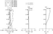
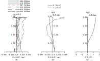
请参阅图2中的(A),图2中的(A)示出了第一实施例中的光学镜头100在波长为435nm、470nm、510nm、587.5615nm、610nm和650nm下的纵向球差图。图2中的(A)中,沿X轴方向的横坐标表示焦点偏移,沿Y轴方向的纵坐标表示归一化视场。由图2中的(A)可以看出,第一实施例中的光学镜头100的球差得到了有效控制,说明本实施例中的光学镜头100的成像质量较好。Please refer to (A) in FIG. 2. (A) in FIG. 2 shows the longitudinal spherical aberration diagrams of theoptical lens 100 in the first embodiment at wavelengths of 435nm, 470nm, 510nm, 587.5615nm, 610nm and 650nm . In (A) of FIG. 2 , the abscissa along the X-axis direction represents focus shift, and the ordinate along the Y-axis direction represents a normalized field of view. It can be seen from (A) in FIG. 2 that the spherical aberration of theoptical lens 100 in the first embodiment is effectively controlled, indicating that the imaging quality of theoptical lens 100 in this embodiment is better.

请参阅图2中的(B),图2中的(B)为第一实施例中的光学镜头100在波长为587.5615nm下的像散曲线图。其中,沿X轴方向的横坐标表示焦点偏移,沿Y轴方向的纵坐标表示像高,单位为mm。像散曲线图中的T表示成像面101在子午方向的弯曲,S表示成像面101在弧矢方向的弯曲,由图2中的(B)可以看出,在该波长下,光学镜头100的像散得到了较好的补偿。Please refer to (B) in FIG. 2 . (B) in FIG. 2 is an astigmatism curve of theoptical lens 100 in the first embodiment at a wavelength of 587.5615 nm. Wherein, the abscissa along the X-axis direction represents the focal shift, and the ordinate along the Y-axis direction represents the image height, and the unit is mm. T in the astigmatism curve diagram represents the curvature of theimaging surface 101 in the meridional direction, and S represents the curvature of theimaging surface 101 in the sagittal direction. It can be seen from (B) in FIG. 2 that at this wavelength, theoptical lens 100 Astigmatism is better compensated.

请参阅图2中的(C),图2中的(C)为第一实施例中的光学镜头100在波长为587.5615nm下的畸变曲线图。其中,沿X轴方向的横坐标表示畸变,沿Y轴方向的纵坐标表示像高,单位为mm。由图2中的(C)可以看出,在波长587.5615nm下,该光学镜头100的畸变得到了很好的校正。Please refer to (C) in FIG. 2 . (C) in FIG. 2 is a distortion curve of theoptical lens 100 in the first embodiment at a wavelength of 587.5615 nm. Wherein, the abscissa along the X-axis direction represents the distortion, and the ordinate along the Y-axis direction represents the image height, and the unit is mm. It can be seen from (C) in FIG. 2 that the distortion of theoptical lens 100 is well corrected at the wavelength of 587.5615 nm.

第二实施例second embodiment

请参照图3,图3为本申请第二实施例的光学镜头100的结构示意图。光学镜头100包括沿光轴O从物侧向像侧依次设置的光阑102、第一透镜L1、第二透镜L2、第三透镜L3、第四透镜L4、第五透镜L5和滤光片L6。Please refer to FIG. 3 , which is a schematic structural diagram of anoptical lens 100 according to a second embodiment of the present application. Theoptical lens 100 includes adiaphragm 102, a first lens L1, a second lens L2, a third lens L3, a fourth lens L4, a fifth lens L5 and a filter L6 arranged in sequence along the optical axis O from the object side to the image side .

进一步地,在第二实施例中,各个透镜的屈折力与第一实施例中的各个透镜的屈折力一致。同时,在第二实施例中,各个透镜的面型与第一实施例中的各个透镜的面型一致。Further, in the second embodiment, the refractive power of each lens is consistent with the refractive power of each lens in the first embodiment. Meanwhile, in the second embodiment, the surface type of each lens is consistent with the surface type of each lens in the first embodiment.

在第二实施例中,以光学镜头100的焦距f=8.86mm、光学镜头100的视场角FOV=37.89°、光学镜头100的光学总长TTL=7.68mm、光圈数FNO=2.49为例。该第二实施例中的其他各项参数由下列表3给出,且其中各参数的定义可由前述实施例的说明中得出,此处不加以赘述。可以理解的是,表3中的Y半径、厚度、焦距的单位均为mm。且表3中各个透镜的折射率、阿贝数、焦距的参考波长为587.6nm。In the second embodiment, the focal length of theoptical lens 100 is f=8.86mm, the field of view FOV of theoptical lens 100 is 37.89°, the total optical length of theoptical lens 100 is TTL=7.68mm, and the number of apertures is FNO=2.49. The other parameters in the second embodiment are given in Table 3 below, and the definition of each parameter can be obtained from the description of the foregoing embodiments, and will not be repeated here. It can be understood that the units of Y radius, thickness and focal length in Table 3 are mm. And the reference wavelength of the refractive index, Abbe number, and focal length of each lens in Table 3 is 587.6 nm.

表3table 3

Figure 758694DEST_PATH_IMAGE004

在第二实施例中,表4给出了可用于第二实施例中各个非球面镜面的高次项系数,其中,各个非球面面型可由第一实施例中给出的公式限定。In the second embodiment, Table 4 shows the high-order term coefficients that can be used for each aspheric mirror surface in the second embodiment, wherein each aspheric surface type can be defined by the formula given in the first embodiment.

表4Table 4

Figure 838645DEST_PATH_IMAGE005

请参阅图4,由图4中的(A)纵向球差图,(B)像散曲线图以及(C)畸变曲线图可知,光学镜头100的纵向球差、像散和畸变均得到良好的控制,从而该实施例的光学镜头100拥有良好的成像品质。此外,关于图4中的(A)、图4中的(B)以及图4中的(C)中各曲线对应的波长可参考第一实施例中关于图2中的(A)、图2中的(B)、图2中的(C)所描述的内容,此处不再赘述。Please refer to Fig. 4, from the (A) longitudinal spherical aberration diagram, (B) astigmatism curve diagram and (C) distortion curve diagram in Fig. 4, it can be seen that the longitudinal spherical aberration, astigmatism and distortion of theoptical lens 100 are well obtained control, so that theoptical lens 100 of this embodiment has good imaging quality. In addition, for the wavelengths corresponding to the curves in (A) in Figure 4, (B) in Figure 4, and (C) in Figure 4, please refer to (A) in Figure 2 and Figure 2 in the first embodiment. The content described in (B) in Figure 2 and (C) in Figure 2 will not be repeated here.

第三实施例third embodiment

请参照图5,图5示出了本申请第三实施例的光学镜头100的结构示意图。光学镜头100包括沿光轴O从物侧向像侧依次设置的光阑102、第一透镜L1、第二透镜L2、第三透镜L3、第四透镜L4、第五透镜L5和滤光片L6。Please refer to FIG. 5 , which shows a schematic structural diagram of anoptical lens 100 according to a third embodiment of the present application. Theoptical lens 100 includes adiaphragm 102, a first lens L1, a second lens L2, a third lens L3, a fourth lens L4, a fifth lens L5 and a filter L6 arranged in sequence along the optical axis O from the object side to the image side .

进一步地,在第三实施例中,各个透镜的屈折力与第一实施例中的各个透镜的屈折力一致。同时,在第三实施例中,各个透镜的面型与第一实施例中的各个透镜的面型的区别在于:第四透镜L4的像侧面S8于近光轴O处为凸面。Further, in the third embodiment, the refractive power of each lens is consistent with that of the first embodiment. Meanwhile, in the third embodiment, the surface shape of each lens differs from that in the first embodiment in that: the image side S8 of the fourth lens L4 is convex at the near optical axis O.

在第三实施例中,以光学镜头100的焦距f=8.67mm、光学镜头100的视场角FOV=38.09°、光学镜头100的光学总长TTL=7.48mm、光圈数FNO=2.48为例。该第三实施例中的其他各项参数由下列表5给出,且其中各参数的定义可由前述说明中得出,此处不加以赘述。可以理解的是,表5中的Y半径、厚度、焦距的单位均为mm。且表5中各个透镜的折射率、阿贝数、焦距的参考波长为587.6nm。In the third embodiment, the focal length of theoptical lens 100 is f=8.67mm, the field of view FOV of theoptical lens 100 is 38.09°, the total optical length of theoptical lens 100 is TTL=7.48mm, and the number of apertures is FNO=2.48. The other parameters in the third embodiment are given in Table 5 below, and the definition of each parameter can be obtained from the foregoing description, and will not be repeated here. It can be understood that the units of Y radius, thickness, and focal length in Table 5 are mm. And the reference wavelength of the refractive index, Abbe number, and focal length of each lens in Table 5 is 587.6 nm.

表5table 5

Figure 192266DEST_PATH_IMAGE006

在第三实施例中,表6给出了可用于第三实施例中各个非球面镜面的高次项系数,其中,各个非球面面型可由第一实施例中给出的公式限定。In the third embodiment, Table 6 shows the high-order term coefficients that can be used for each aspheric mirror surface in the third embodiment, wherein each aspheric surface type can be defined by the formula given in the first embodiment.

表6Table 6

Figure 724879DEST_PATH_IMAGE007

请参阅图6,由图6中的(A)纵向球差图,(B)像散曲线图以及(C)畸变曲线图可知,光学镜头100的纵向球差、像散和畸变均得到良好的控制,从而该实施例的光学镜头100拥有良好的成像品质。此外,关于图6中的(A)、图6中的(B)以及图6中的(C)中各曲线对应的波长可参考第一实施例中关于图2中的(A)、图2中的(B)、图2中的(C)所描述的内容,此处不再赘述。Please refer to FIG. 6, from the (A) longitudinal spherical aberration diagram, (B) astigmatism curve diagram and (C) distortion curve diagram in FIG. control, so that theoptical lens 100 of this embodiment has good imaging quality. In addition, for the wavelengths corresponding to the curves in (A) in Figure 6, (B) in Figure 6, and (C) in Figure 6, please refer to (A) in Figure 2 and Figure 2 in the first embodiment. The content described in (B) in Figure 2 and (C) in Figure 2 will not be repeated here.

第四实施例Fourth embodiment

请参阅图7,为本申请第四实施例公开的光学镜头100的结构示意图。光学镜头100包括沿光轴O从物侧向像侧依次设置的光阑102、第一透镜L1、第二透镜L2、第三透镜L3、第四透镜L4、第五透镜L5和滤光片L6。Please refer to FIG. 7 , which is a schematic structural diagram of theoptical lens 100 disclosed in the fourth embodiment of the present application. Theoptical lens 100 includes adiaphragm 102, a first lens L1, a second lens L2, a third lens L3, a fourth lens L4, a fifth lens L5 and a filter L6 arranged in sequence along the optical axis O from the object side to the image side .

进一步地,在第四实施例中,各个透镜的屈折力与第一实施例中的各个透镜的屈折力一致。而在第四实施例中,各个透镜的面型与第一实施例中的各个透镜的面型的区别在于:第四透镜L4的像侧面S8于近光轴O处为凸面。Further, in the fourth embodiment, the refractive power of each lens is consistent with the refractive power of each lens in the first embodiment. In the fourth embodiment, the surface shape of each lens differs from that of the first embodiment in that: the image side S8 of the fourth lens L4 is convex at the near optical axis O.

在第四实施例中,以光学镜头100的焦距f=8.67mm、光学镜头100的视场角FOV=34.67°、光学镜头100的光学总长TTL=7.50mm、光圈数FNO=2.48为例。该第四实施例中的其他各项参数由下列表7给出,且其中各参数的定义可由前述说明中得出,此处不加以赘述。可以理解的是,表7中的Y半径、厚度、焦距的单位均为mm。且表7中各个透镜的折射率、阿贝数、焦距的参考波长为587.6nm。In the fourth embodiment, the focal length of theoptical lens 100 is f=8.67mm, the field of view FOV of theoptical lens 100 is 34.67°, the total optical length of theoptical lens 100 is TTL=7.50mm, and the number of apertures is FNO=2.48. The other parameters in the fourth embodiment are given in Table 7 below, and the definition of each parameter can be obtained from the foregoing description, and will not be repeated here. It can be understood that the units of Y radius, thickness and focal length in Table 7 are mm. And the reference wavelength of the refractive index, Abbe number, and focal length of each lens in Table 7 is 587.6 nm.

表7Table 7

Figure 454937DEST_PATH_IMAGE008

在第四实施例中,表8给出了可用于第四实施例中各个非球面镜面的高次项系数,其中,各个非球面面型可由第一实施例中给出的公式限定。In the fourth embodiment, Table 8 shows the high-order term coefficients that can be used for each aspheric mirror surface in the fourth embodiment, wherein each aspheric surface type can be defined by the formula given in the first embodiment.

表8Table 8

Figure 389395DEST_PATH_IMAGE009

请参阅图8,由图8中的(A)纵向球差图,(B)像散曲线图以及(C)畸变曲线图可知,光学镜头100的纵向球差、像散和畸变均得到良好的控制,从而该实施例的光学镜头100拥有良好的成像品质。此外,关于图8中的(A)、图8中的(B)以及图8中的(C)中各曲线对应的波长可参考第一实施例中关于图2中的(A)、图2中的(B)、图2中的(C)所描述的内容,此处不再赘述。Please refer to FIG. 8, from the (A) longitudinal spherical aberration diagram, (B) astigmatism curve diagram and (C) distortion curve diagram in FIG. control, so that theoptical lens 100 of this embodiment has good imaging quality. In addition, for the wavelengths corresponding to the curves in (A) in Figure 8, (B) in Figure 8, and (C) in Figure 8, please refer to (A) in Figure 2 and Figure 2 in the first embodiment. The content described in (B) in Figure 2 and (C) in Figure 2 will not be repeated here.

第五实施例fifth embodiment

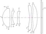
请参阅图9,为本申请第五实施例公开的光学镜头100的结构示意图。光学镜头100包括沿光轴O从物侧向像侧依次设置的光阑102、第一透镜L1、第二透镜L2、第三透镜L3、第四透镜L4、第五透镜L5和滤光片L6。Please refer to FIG. 9 , which is a schematic structural diagram of theoptical lens 100 disclosed in the fifth embodiment of the present application. Theoptical lens 100 includes adiaphragm 102, a first lens L1, a second lens L2, a third lens L3, a fourth lens L4, a fifth lens L5 and a filter L6 arranged in sequence along the optical axis O from the object side to the image side .

进一步地,在第五实施例中,各个透镜的屈折力与第一实施例中的各个透镜的屈折力一致。同时,在第五实施例中,各个透镜的面型与第一实施例中的各个透镜的面型一致。Further, in the fifth embodiment, the refractive power of each lens is consistent with the refractive power of each lens in the first embodiment. Meanwhile, in the fifth embodiment, the surface type of each lens is identical to that of each lens in the first embodiment.

在第五实施例中,以光学镜头100的焦距f=8.68mm、光学镜头100的视场角FOV=37.69°、光学镜头100的光学总长TTL=7.50mm、光圈数FNO=2.49为例。该第五实施例中的其他各项参数由下列表9给出,且其中各参数的定义可由前述说明中得出,此处不加以赘述。可以理解的是,表9中的Y半径、厚度、焦距的单位均为mm。且表9中各个透镜的折射率、阿贝数、焦距的参考波长为587.6nm。In the fifth embodiment, the focal length of theoptical lens 100 is f=8.68 mm, the field of view FOV of theoptical lens 100 is 37.69°, the total optical length TTL of theoptical lens 100 is 7.50 mm, and the aperture number FNO is 2.49. The other parameters in the fifth embodiment are given in Table 9 below, and the definition of each parameter can be obtained from the foregoing description, and will not be repeated here. It can be understood that the units of Y radius, thickness and focal length in Table 9 are mm. And the reference wavelength of the refractive index, Abbe number, and focal length of each lens in Table 9 is 587.6 nm.

表9Table 9

Figure 179497DEST_PATH_IMAGE010

在第五实施例中,表10给出了可用于第五实施例中各个非球面镜面的高次项系数,其中,各个非球面面型可由第一实施例中给出的公式限定。In the fifth embodiment, Table 10 shows the higher-order coefficients that can be used for each aspheric mirror surface in the fifth embodiment, wherein each aspheric surface type can be defined by the formula given in the first embodiment.

表10Table 10

Figure 199405DEST_PATH_IMAGE011

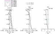
请参阅图10,由图10中的(A)纵向球差图,(B)像散曲线图以及(C)畸变曲线图可知,光学镜头100的纵向球差、像散和畸变均得到良好的控制,从而该实施例的光学镜头100拥有良好的成像品质。此外,关于图10中的(A)、图10中的(B)以及图10中的(C)中各曲线对应的波长可参考第一实施例中关于图2中的(A)、图2中的(B)、图2中的(C)所描述的内容,此处不再赘述。Please refer to FIG. 10, from the (A) longitudinal spherical aberration diagram, (B) astigmatism curve diagram and (C) distortion curve diagram in FIG. control, so that theoptical lens 100 of this embodiment has good imaging quality. In addition, for the wavelengths corresponding to the curves in (A) in Figure 10, (B) in Figure 10 and (C) in Figure 10, please refer to (A) in Figure 2 and Figure 2 in the first embodiment The content described in (B) in Figure 2 and (C) in Figure 2 will not be repeated here.

第六实施例Sixth embodiment

请参阅图11,为本申请第六实施例公开的光学镜头100的结构示意图。光学镜头100包括沿光轴O从物侧向像侧依次设置的光阑102、第一透镜L1、第二透镜L2、第三透镜L3、第四透镜L4、第五透镜L5和滤光片L6。Please refer to FIG. 11 , which is a schematic structural diagram of theoptical lens 100 disclosed in the sixth embodiment of the present application. Theoptical lens 100 includes adiaphragm 102, a first lens L1, a second lens L2, a third lens L3, a fourth lens L4, a fifth lens L5 and a filter L6 arranged in sequence along the optical axis O from the object side to the image side .

进一步地,在第六实施例中,各个透镜的屈折力与第一实施例中的各个透镜的屈折力一致。同时,在第六实施例中,各个透镜的面型与第一实施例中的各个透镜的面型一致。Further, in the sixth embodiment, the refractive power of each lens is consistent with that of the first embodiment. Meanwhile, in the sixth embodiment, the surface type of each lens is consistent with the surface type of each lens in the first embodiment.

在第六实施例中,以光学镜头100的焦距f=8.67mm、光学镜头100的视场角FOV=37.77°、光学镜头100的光学总长TTL=7.48mm、光圈数FNO=2.47为例。该第六实施例中的其他各项参数由下列表11给出,且其中各参数的定义可由前述说明中得出,此处不加以赘述。可以理解的是,表11中的Y半径、厚度、焦距的单位均为mm。且表11中各个透镜的折射率、阿贝数、焦距的参考波长为587.6nm。In the sixth embodiment, the focal length of theoptical lens 100 is f=8.67mm, the field of view FOV of theoptical lens 100 is 37.77°, the total optical length of theoptical lens 100 is TTL=7.48mm, and the number of apertures is FNO=2.47. The other parameters in the sixth embodiment are given in Table 11 below, and the definition of each parameter can be obtained from the foregoing description, and will not be repeated here. It can be understood that the units of Y radius, thickness and focal length in Table 11 are mm. And the reference wavelength of the refractive index, Abbe number, and focal length of each lens in Table 11 is 587.6 nm.

表11Table 11

Figure 201997DEST_PATH_IMAGE012

在第六实施例中,表12给出了可用于第六实施例中各个非球面镜面的高次项系数,其中,各个非球面面型可由第一实施例中给出的公式限定。In the sixth embodiment, Table 12 shows the high-order term coefficients that can be used for each aspheric mirror surface in the sixth embodiment, wherein each aspheric surface type can be defined by the formula given in the first embodiment.

表12Table 12

Figure 256540DEST_PATH_IMAGE013

请参阅图12,由图12中的(A)纵向球差图,(B)像散曲线图以及(C)畸变曲线图可知,光学镜头100的纵向球差、像散和畸变均得到良好的控制,从而该实施例的光学镜头100拥有良好的成像品质。此外,关于图12中的(A)、图12中的(B)以及图12中的(C)中各曲线对应的波长可参考第一实施例中关于图2中的(A)、图2中的(B)、图2中的(C)所描述的内容,此处不再赘述。Please refer to Fig. 12, from the (A) longitudinal spherical aberration diagram, (B) astigmatism curve diagram and (C) distortion curve diagram in Fig. 12, it can be seen that the longitudinal spherical aberration, astigmatism and distortion of theoptical lens 100 are well obtained control, so that theoptical lens 100 of this embodiment has good imaging quality. In addition, for the wavelengths corresponding to the curves in (A) in Figure 12, (B) in Figure 12 and (C) in Figure 12, please refer to (A) in Figure 2 and Figure 2 in the first embodiment The content described in (B) in Figure 2 and (C) in Figure 2 will not be repeated here.

第七实施例Seventh embodiment

请参阅图13,为本申请第七实施例公开的光学镜头100的结构示意图。光学镜头100包括沿光轴O从物侧向像侧依次设置的光阑102、第一透镜L1、第二透镜L2、第三透镜L3、第四透镜L4、第五透镜L5和滤光片L6。Please refer to FIG. 13 , which is a schematic structural diagram of theoptical lens 100 disclosed in the seventh embodiment of the present application. Theoptical lens 100 includes adiaphragm 102, a first lens L1, a second lens L2, a third lens L3, a fourth lens L4, a fifth lens L5 and a filter L6 arranged in sequence along the optical axis O from the object side to the image side .

进一步地,在第七实施例中,各个透镜的屈折力与第一实施例中的各个透镜的屈折力一致。同时,在第七实施例中,各个透镜的面型与第一实施例中的各个透镜的面型的区别在于:第三透镜L3的物侧面S5、像侧面S6于近光轴O处分别为凸面和凹面,第四透镜L4的像侧面S8于近光轴O处为凸面。Further, in the seventh embodiment, the refractive power of each lens is consistent with that of the first embodiment. At the same time, in the seventh embodiment, the difference between the surface type of each lens and the surface type of each lens in the first embodiment is that: the object side S5 and the image side S6 of the third lens L3 at the near optical axis O are respectively Convex and concave, the image side S8 of the fourth lens L4 is convex at the near optical axis O.

在第七实施例中,以光学镜头100的焦距f=8.67mm、光学镜头100的视场角FOV=38.09°、光学镜头100的光学总长TTL=7.48mm、光圈数FNO=2.49为例。该第七实施例中的其他各项参数由下列表13给出,且其中各参数的定义可由前述说明中得出,此处不加以赘述。可以理解的是,表13中的Y半径、厚度、焦距的单位均为mm。且表13中各个透镜的折射率、阿贝数、焦距的参考波长为587.6nm。In the seventh embodiment, the focal length of theoptical lens 100 is f=8.67mm, the field of view FOV of theoptical lens 100 is 38.09°, the total optical length of theoptical lens 100 is TTL=7.48mm, and the number of apertures is FNO=2.49. The other parameters in the seventh embodiment are given in Table 13 below, and the definition of each parameter can be obtained from the foregoing description, and will not be repeated here. It can be understood that the units of the Y radius, thickness and focal length in Table 13 are mm. And the reference wavelength of the refractive index, Abbe number, and focal length of each lens in Table 13 is 587.6 nm.

表13Table 13

Figure 951964DEST_PATH_IMAGE014

在第七实施例中,表14给出了可用于第七实施例中各个非球面镜面的高次项系数,其中,各个非球面面型可由第一实施例中给出的公式限定。In the seventh embodiment, Table 14 shows the high-order term coefficients that can be used for each aspheric mirror surface in the seventh embodiment, wherein each aspheric surface type can be defined by the formula given in the first embodiment.

表14Table 14

Figure 724748DEST_PATH_IMAGE015

请参阅图14,由图14中的(A)纵向球差图,(B)像散曲线图以及(C)畸变曲线图可知,光学镜头100的纵向球差、像散和畸变均得到良好的控制,从而该实施例的光学镜头100拥有良好的成像品质。此外,关于图14中的(A)、图14中的(B)以及图14中的(C)中各曲线对应的波长可参考第一实施例中关于图2中的(A)、图2中的(B)、图2中的(C)所描述的内容,此处不再赘述。Please refer to FIG. 14 , from the (A) longitudinal spherical aberration diagram, (B) astigmatism curve diagram and (C) distortion curve diagram in FIG. 14 , it can be seen that the longitudinal spherical aberration, astigmatism and distortion of theoptical lens 100 are all well obtained. control, so that theoptical lens 100 of this embodiment has good imaging quality. In addition, for the wavelengths corresponding to the curves in (A) in Figure 14, (B) in Figure 14, and (C) in Figure 14, please refer to (A) in Figure 2 and Figure 2 in the first embodiment. The content described in (B) in Figure 2 and (C) in Figure 2 will not be repeated here.

请参阅表15,表15为本申请第一实施例至第七实施例中各关系式的比值汇总。Please refer to Table 15. Table 15 is a summary of the ratios of the relational expressions in the first embodiment to the seventh embodiment of the present application.

表15Table 15

Figure 265450DEST_PATH_IMAGE016

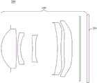
请参阅图15,本申请还公开了一种摄像模组200,摄像模组200包括感光芯片201和上述的光学镜头100,感光芯片201设置于光学镜头100的像侧。具有光学镜头100的摄像模组能够在降低光学镜头100光学总长,实现光学镜头100的轻薄、小型化设计的同时,校正光学镜头100的畸变、像散及场曲等像差,提高光学镜头100的成像品质。Referring to FIG. 15 , the present application also discloses acamera module 200 . Thecamera module 200 includes aphotosensitive chip 201 and the aforementionedoptical lens 100 . Thephotosensitive chip 201 is disposed on the image side of theoptical lens 100 . The camera module with theoptical lens 100 can reduce the total optical length of theoptical lens 100, realize the thin and light design of theoptical lens 100, and at the same time, correct the aberrations such as distortion, astigmatism and field curvature of theoptical lens 100, and improve theoptical lens 100. image quality.

请参阅图16,本申请还公开了一种电子设备,所述电子设备300包括壳体301和上述的摄像模组200,摄像模组200设于壳体301以获取影像信息。其中,电子设备300可以但不限于手机、平板电脑、笔记本电脑、智能手表、监控器等。可以理解的,具有上述摄像模组200的电子设备300,也具有上述光学镜头100的全部技术效果,即,能够在降低光学镜头100光学总长,实现光学镜头100的轻薄、小型化设计的同时,校正光学镜头100的畸变、像散及场曲等像差,提高光学镜头100的成像品质。Please refer to FIG. 16 , the present application also discloses an electronic device. Theelectronic device 300 includes ahousing 301 and theaforementioned camera module 200 . Thecamera module 200 is set on thehousing 301 to acquire image information. Wherein, theelectronic device 300 may be, but not limited to, a mobile phone, a tablet computer, a notebook computer, a smart watch, a monitor, and the like. It can be understood that theelectronic device 300 with the above-mentionedcamera module 200 also has all the technical effects of the above-mentionedoptical lens 100, that is, it can reduce the total optical length of theoptical lens 100 and realize the light and thin, miniaturized design of theoptical lens 100. Aberrations such as distortion, astigmatism, and field curvature of theoptical lens 100 are corrected to improve the imaging quality of theoptical lens 100 .

以上对本发明实施例公开的光学镜头、摄像模组及电子设备进行了详细介绍,本文中应用了具体个例对本发明的原理及实施方式进行了阐述,以上实施例的说明只是用于帮助理解本发明的光学镜头、摄像模组及电子设备及其核心思想;同时,对于本领域的一般技术人员,依据本发明的思想,在具体实施方式及应用范围上均会有改变之处,综上,本说明书内容不应理解为对本发明的限制。The optical lens, camera module and electronic equipment disclosed in the embodiments of the present invention have been introduced in detail above. In this paper, specific examples have been used to illustrate the principles and implementation methods of the present invention. The descriptions of the above embodiments are only used to help understand the present invention. Invented optical lens, camera module and electronic equipment and their core ideas; at the same time, for those of ordinary skill in the art, according to the idea of the present invention, there will be changes in the specific implementation and application range. In summary, The contents of this description should not be construed as limiting the present invention.

Claims (10)

1. An optical lens system includes five lens elements with refractive power, wherein the five lens elements include, in order from an object side to an image side along an optical axis, a first lens element, a second lens element, a third lens element, a fourth lens element and a fifth lens element;
the first lens element with positive refractive power has a convex object-side surface at a paraxial region thereof and a convex image-side surface at a paraxial region thereof;
the second lens element with negative refractive power has a convex object-side surface at paraxial region and a concave image-side surface at paraxial region;
the third lens element with negative refractive power;
the fourth lens element with negative refractive power has a concave object-side surface at paraxial region;
the fifth lens element with positive refractive power has a convex object-side surface at a paraxial region, and has a convex image-side surface at a paraxial region;
the optical lens satisfies the following relation: -6.5 yarn-woven R10/f < -0.1, 3 yarn-woven AT23/AT12<24, 0.13 yarn-woven CT3/AT34<0.2, -1.6 yarn-woven SAG41/CT4< -0.7, 1.30 yarn-woven MAX45/MIN45<3.55 and-4 yarn-woven SAG42/MIN45< -0.4;
wherein, R10 is the image side of fifth lens in the radius of curvature of optical axis department, f does optical lens's focus, AT12 is the image side of first lens extremely the object side of second lens is in the air gap on the optical axis, AT23 is the image side of second lens extremely the object side of third lens is in the air gap on the optical axis, AT34 is the image side of third lens extremely the object side of fourth lens is in the air gap on the optical axis, CT3 is the third lens in the thickness on the optical axis, CT4 is the fourth lens in the thickness on the optical axis, SAG41 is the intersection point of the object side of fourth lens with the optical axis extremely the maximum effective radius of the object side of fourth lens is in parallel with the distance on the optical axis direction, SAG42 is the intersection point of the image side of fourth lens with the optical axis extremely the maximum effective radius of the image side of fourth lens is in parallel with the distance on the optical axis direction, MIN45 is the side of fourth lens extremely the surface of fifth lens is in the air gap on the optical axis extremely the MAX, the optical axis extremely the optical axis is parallel with the maximum effective radius of fourth lens on the optical axis.
2. An optical lens according to claim 1, characterized in that the optical lens satisfies the following relation:
0.18<AT34/TTL<0.3;
wherein, TTL is a distance on the optical axis from the object-side surface of the first lens element to the image plane of the optical lens.
3. An optical lens according to claim 1, wherein the optical lens satisfies the following relation:
0.8-plus TTL/f is less than 0.9; and/or, 0.13-woven fabric BFL/TTL is less than 0.18;
wherein, TTL is a distance on the optical axis from the object-side surface of the first lens element to the imaging surface of the optical lens, and BFL is a distance on the optical axis from the image-side surface of the fifth lens element to the imaging surface of the optical lens.
4. An optical lens according to claim 1, wherein the optical lens satisfies the following relation:
0.65< ∑ ET/Σ CT <0.75, and/or, 3.5< -f/Σ ET <4.5;
Σ ET is a sum of distances in an optical axis direction from a maximum effective aperture position of an object side surface to a maximum effective aperture position of an image side surface of each of the first to fifth lenses, Σ CT is a sum of thicknesses of the first to fifth lenses in the optical axis direction, and BFL is a distance in the optical axis direction from the image side surface of the fifth lens to an image plane of the optical lens.
5. An optical lens according to claim 1, wherein the optical lens satisfies the following relation:
0.8<CT3/CT2<1.5;
wherein CT2 is the thickness of the second lens element on the optical axis.
6. An optical lens according to claim 1, wherein the optical lens satisfies the following relation:
1.2-woven fabric DT12/DT22<1.4; and/or, 1.1-Ap DT22/DT31<1.3; and/or, 1.5< (DL 41+ DL 51)/Imgh <1.7;
wherein DT12 is the maximum effective half aperture of the image-side surface of the first lens element, DT22 is the maximum effective half aperture of the image-side surface of the second lens element, and DT31 is the maximum effective half aperture of the object-side surface of the third lens element; DL41 is the maximum effective diameter of the object-side surface of the fourth lens element, DL51 is the maximum effective diameter of the object-side surface of the fifth lens element, and Imgh is the image height corresponding to the maximum field angle.
7. An optical lens according to claim 1, wherein the optical lens satisfies the following relation:
1.55-sf1/R1 <1.80, and/or-14-sR2/f 1< -3;
wherein R1 is a curvature radius of an object-side surface of the first lens element at the optical axis, R2 is a curvature radius of an image-side surface of the first lens element at the optical axis, and f1 is a focal length of the first lens element.
8. An optical lens according to claim 1, wherein the optical lens satisfies the following relation:
0.24<(SAG11+SAG21)/TTL<0.3;
SAG11 is a distance from an intersection point of an object side surface of the first lens element and the optical axis to a maximum effective radius of an object side surface of the first lens element in a direction parallel to the optical axis, SAG21 is a distance from an intersection point of an object side surface of the second lens element and the optical axis to a maximum effective radius of an object side surface of the second lens element in a direction parallel to the optical axis, and TTL is a distance from the object side surface of the first lens element to an image plane of the optical lens element in the optical axis.
9. A camera module, comprising a photo sensor chip and the optical lens of any one of claims 1-8, wherein the photo sensor chip is disposed on an image side of the optical lens.
10. An electronic device, comprising a housing and the camera module of claim 9, wherein the camera module is disposed in the housing.
CN202211317687.2A2022-10-262022-10-26Optical lens, camera module and electronic equipmentActiveCN115373119B (en)

Priority Applications (1)

Application NumberPriority DateFiling DateTitle
CN202211317687.2ACN115373119B (en)2022-10-262022-10-26Optical lens, camera module and electronic equipment

Applications Claiming Priority (1)

Application NumberPriority DateFiling DateTitle
CN202211317687.2ACN115373119B (en)2022-10-262022-10-26Optical lens, camera module and electronic equipment

Publications (2)

Publication NumberPublication Date
CN115373119A CN115373119A (en)2022-11-22
CN115373119Btrue CN115373119B (en)2023-03-10

Family

ID=84074346

Family Applications (1)

Application NumberTitlePriority DateFiling Date
CN202211317687.2AActiveCN115373119B (en)2022-10-262022-10-26Optical lens, camera module and electronic equipment

Country Status (1)

CountryLink
CN (1)CN115373119B (en)

Families Citing this family (3)

* Cited by examiner, † Cited by third party
Publication numberPriority datePublication dateAssigneeTitle
CN116430549B (en)*2023-04-062024-01-12广东旭业光电科技股份有限公司Telephoto lens and electronic equipment
CN116609924A (en)*2023-06-202023-08-18浙江舜宇光学有限公司Optical lens system
CN119986981B (en)*2025-04-142025-09-02江西联益光学有限公司 Optical lens

Citations (4)

* Cited by examiner, † Cited by third party
Publication numberPriority datePublication dateAssigneeTitle
CN104597586A (en)*2013-10-312015-05-06苹果公司Small form factor telephoto camera
JP2021047315A (en)*2019-09-192021-03-25カンタツ株式会社Image capturing lens
CN113640953A (en)*2019-03-272021-11-12康达智株式会社Camera lens
CN114063248A (en)*2020-07-292022-02-18大立光电股份有限公司Imaging optical lens assembly, image capturing device and electronic device

Family Cites Families (1)

* Cited by examiner, † Cited by third party
Publication numberPriority datePublication dateAssigneeTitle
CN114740604B (en)*2022-04-262023-09-05江西晶超光学有限公司 Optical systems, camera modules and electronics

Patent Citations (4)

* Cited by examiner, † Cited by third party
Publication numberPriority datePublication dateAssigneeTitle
CN104597586A (en)*2013-10-312015-05-06苹果公司Small form factor telephoto camera
CN113640953A (en)*2019-03-272021-11-12康达智株式会社Camera lens
JP2021047315A (en)*2019-09-192021-03-25カンタツ株式会社Image capturing lens
CN114063248A (en)*2020-07-292022-02-18大立光电股份有限公司Imaging optical lens assembly, image capturing device and electronic device

Also Published As

Publication numberPublication date
CN115373119A (en)2022-11-22

Similar Documents

PublicationPublication DateTitle
CN115373119B (en)Optical lens, camera module and electronic equipment
WO2020019705A1 (en)Camera lens, camera module, and terminal
CN113933968B (en)Optical lens, camera module and electronic equipment
CN112363302B (en) Optical systems, camera modules and electronic equipment
CN113552697A (en) Optical lens, camera module and electronic equipment
CN114296213B (en)Optical lens, camera module and electronic equipment
CN111812806A (en) Optical systems, camera modules and electronic equipment
CN114355579A (en) Optical lens, camera module and electronic equipment
CN112987256B (en)Optical system, camera module and electronic equipment
CN113552695B (en) Optical zoom system, lens module and electronic equipment
CN114415343A (en)Optical system, camera module and electronic equipment
CN114326026A (en)Optical lens, camera module and electronic equipment
CN114740599A (en) Optical systems, camera modules and electronic equipment
CN114114617A (en)Optical system, lens module and electronic equipment
CN115390226B (en) Optical lens, camera module and electronic equipment
CN115480364B (en) Optical lenses, camera modules and electronic equipment
CN114578525B (en)Optical system, lens module and electronic equipment
CN114721126B (en) Optical lens, camera module and electronic equipment
CN113900226B (en) Optical systems, imaging modules and electronic equipment
CN113933966B (en) Optical lens, camera module and electronic equipment
CN113741005B (en) Optical system, imaging module and electronic equipment
CN214845997U (en)Optical system, camera module and electronic equipment
CN116027527B (en)Optical lens, camera module and electronic equipment
CN114326052B (en)Optical system, image capturing module and electronic equipment
CN114690378B (en)Optical imaging system, lens module and electronic equipment

Legal Events

DateCodeTitleDescription
PB01Publication
PB01Publication
SE01Entry into force of request for substantive examination
GR01Patent grant
GR01Patent grant
CP03Change of name, title or address

Address after:330096 No.699 Tianxiang North Avenue, Nanchang hi tech Industrial Development Zone, Jiangxi Province

Patentee after:Jiangxi Oufei Optics Co.,Ltd.

Country or region after:China

Address before:No. 699 Tianxiang North Avenue, Nanchang High tech Industrial Development Zone, Nanchang City, Jiangxi Province

Patentee before:Jiangxi Jingchao optics Co.,Ltd.

Country or region before:China


[8]ページ先頭

©2009-2025 Movatter.jp