CN115371544A - Surveying device with image evaluator for determining spatial attitude of target axis - Google Patents
Surveying device with image evaluator for determining spatial attitude of target axisDownload PDFInfo
- Publication number
- CN115371544A CN115371544ACN202210507133.2ACN202210507133ACN115371544ACN 115371544 ACN115371544 ACN 115371544ACN 202210507133 ACN202210507133 ACN 202210507133ACN 115371544 ACN115371544 ACN 115371544A
- Authority
- CN
- China
- Prior art keywords
- surveying device
- camera
- axis
- rotation
- alignment
- Prior art date
- Legal status (The legal status is an assumption and is not a legal conclusion. Google has not performed a legal analysis and makes no representation as to the accuracy of the status listed.)
- Granted
Links
Images


Classifications
- G—PHYSICS
- G01—MEASURING; TESTING
- G01B—MEASURING LENGTH, THICKNESS OR SIMILAR LINEAR DIMENSIONS; MEASURING ANGLES; MEASURING AREAS; MEASURING IRREGULARITIES OF SURFACES OR CONTOURS
- G01B11/00—Measuring arrangements characterised by the use of optical techniques
- G01B11/002—Measuring arrangements characterised by the use of optical techniques for measuring two or more coordinates
- G—PHYSICS
- G06—COMPUTING OR CALCULATING; COUNTING
- G06T—IMAGE DATA PROCESSING OR GENERATION, IN GENERAL
- G06T7/00—Image analysis
- G06T7/70—Determining position or orientation of objects or cameras
- G06T7/73—Determining position or orientation of objects or cameras using feature-based methods
- G06T7/74—Determining position or orientation of objects or cameras using feature-based methods involving reference images or patches
- G—PHYSICS
- G01—MEASURING; TESTING
- G01C—MEASURING DISTANCES, LEVELS OR BEARINGS; SURVEYING; NAVIGATION; GYROSCOPIC INSTRUMENTS; PHOTOGRAMMETRY OR VIDEOGRAMMETRY
- G01C15/00—Surveying instruments or accessories not provided for in groups G01C1/00 - G01C13/00
- G01C15/002—Active optical surveying means
- G—PHYSICS
- G01—MEASURING; TESTING
- G01C—MEASURING DISTANCES, LEVELS OR BEARINGS; SURVEYING; NAVIGATION; GYROSCOPIC INSTRUMENTS; PHOTOGRAMMETRY OR VIDEOGRAMMETRY
- G01C3/00—Measuring distances in line of sight; Optical rangefinders
- G01C3/02—Details
- H—ELECTRICITY
- H04—ELECTRIC COMMUNICATION TECHNIQUE
- H04N—PICTORIAL COMMUNICATION, e.g. TELEVISION
- H04N23/00—Cameras or camera modules comprising electronic image sensors; Control thereof
- H04N23/60—Control of cameras or camera modules
- H04N23/695—Control of camera direction for changing a field of view, e.g. pan, tilt or based on tracking of objects
- H—ELECTRICITY
- H04—ELECTRIC COMMUNICATION TECHNIQUE
- H04N—PICTORIAL COMMUNICATION, e.g. TELEVISION
- H04N23/00—Cameras or camera modules comprising electronic image sensors; Control thereof
- H04N23/60—Control of cameras or camera modules
- H04N23/698—Control of cameras or camera modules for achieving an enlarged field of view, e.g. panoramic image capture
- H—ELECTRICITY
- H04—ELECTRIC COMMUNICATION TECHNIQUE
- H04N—PICTORIAL COMMUNICATION, e.g. TELEVISION
- H04N23/00—Cameras or camera modules comprising electronic image sensors; Control thereof
- H04N23/90—Arrangement of cameras or camera modules, e.g. multiple cameras in TV studios or sports stadiums
- G—PHYSICS
- G06—COMPUTING OR CALCULATING; COUNTING
- G06T—IMAGE DATA PROCESSING OR GENERATION, IN GENERAL
- G06T2207/00—Indexing scheme for image analysis or image enhancement
- G06T2207/10—Image acquisition modality
- G06T2207/10028—Range image; Depth image; 3D point clouds
- G—PHYSICS
- G06—COMPUTING OR CALCULATING; COUNTING
- G06T—IMAGE DATA PROCESSING OR GENERATION, IN GENERAL
- G06T2207/00—Indexing scheme for image analysis or image enhancement
- G06T2207/30—Subject of image; Context of image processing
- G06T2207/30204—Marker
- G—PHYSICS
- G06—COMPUTING OR CALCULATING; COUNTING
- G06T—IMAGE DATA PROCESSING OR GENERATION, IN GENERAL
- G06T2207/00—Indexing scheme for image analysis or image enhancement
- G06T2207/30—Subject of image; Context of image processing
- G06T2207/30244—Camera pose
Landscapes
- Engineering & Computer Science (AREA)
- Physics & Mathematics (AREA)
- General Physics & Mathematics (AREA)
- Multimedia (AREA)
- Signal Processing (AREA)
- Radar, Positioning & Navigation (AREA)
- Remote Sensing (AREA)
- Electromagnetism (AREA)
- Computer Vision & Pattern Recognition (AREA)
- Theoretical Computer Science (AREA)
- Length Measuring Devices By Optical Means (AREA)
Abstract
Translated fromChinese
Description
Translated fromChinese技术领域technical field
本发明涉及一种用于空间点的坐标位置确定的勘测装置。The invention relates to a surveying device for coordinate position determination of spatial points.
背景技术Background technique
勘测装置用于需要对空间点的坐标位置进行测量或确定几何关系的各种领域,例如,在施工现场、工业设施或土地勘测中。Surveying devices are used in various fields where it is necessary to measure coordinate positions of points in space or to determine geometric relationships, for example, in construction sites, industrial facilities or land surveys.
例如,勘测装置(例如,实施为全站仪)用于对空间点相对于勘测装置的位置的坐标进行测量,例如,以生成参考了公共坐标系的空间测量点集合。勘测装置的另外的常见功能涉及在环境中放样点,例如其中第一人对齐(align)勘测装置的望远镜目标轴线以匹配计算出的姿态,并朝向目标点(targeting point)引导携带放样装置(例如,包括回射器)的第二人,该目标点由勘测装置的目标轴线和距勘测装置的计算距离限定。For example, a surveying device (eg, implemented as a total station) is used to measure the coordinates of points in space relative to the position of the surveying device, eg, to generate a set of spatially measured points referenced to a common coordinate system. Another common function of surveying devices involves staking out points in the environment, e.g. where a first person aligns the surveying device's telescope target axis to match a calculated pose, and guides a carry-on stakeout device towards a targeting point (e.g. , comprising a retroreflector), the target point is defined by the target axis of the surveying device and the calculated distance from the surveying device.
通常,在勘测装置的各个安装位置,必须正确地确定其准确的外部取向,以便准确地测量测量点相对于勘测装置的位置的3D坐标和/或准确地设置放样过程的目标轴线的姿态。通用设置工作流包括使用GNSS、铅锤确定和/或对具有已知几何关系的一个或多个参考点的测量。Typically, at each installation location of a surveying device, its exact external orientation must be correctly determined in order to accurately measure the 3D coordinates of the measurement point relative to the position of the surveying device and/or accurately set the pose of the target axis for the stakeout process. Common setup workflows include the use of GNSS, plumb bob determination, and/or measurements to one or more reference points with known geometric relationships.
通过示例的方式,针对坐标测量,当今全站仪通常完全水平对齐,例如,在气泡水平仪或倾斜传感器的帮助下,其中,测量点的坐标是利用对准部件(通常称为“望远镜”)瞄准该点的同时通过测量距离、水平角和垂直角得出的。对准部件提供激光束的发送和接收,其中,激光束方向上的距离由电光测距装置测量。电光距离测量是通过发射激光束以提供脉冲飞行时间(TOF)测量方法、相移测量方法或干涉测量方法而进行的。对准部件的取向由勘测装置的角度测量装置(例如,包括角度编码器(诸如,绝对或增量旋转编码器)的测角仪)确定。By way of example, for coordinate measurement today's total stations are usually perfectly aligned horizontally, e.g. with the help of bubble levels or tilt sensors, where the coordinates of the measuring point are aimed using an alignment component (often called a "telescope") The point is obtained by measuring the distance, horizontal angle, and vertical angle at the same time. The alignment part provides for the sending and receiving of the laser beam, wherein the distance in the direction of the laser beam is measured by an electro-optical distance measuring device. Electro-optical distance measurements are performed by emitting a laser beam to provide pulsed time-of-flight (TOF) measurements, phase-shift measurements, or interferometry. The orientation of the alignment component is determined by an angle measuring device of the surveying device, eg a goniometer comprising an angle encoder such as an absolute or incremental rotary encoder.
一旦将勘测装置设置在特定位置,就可以确定环境的多个点的3D坐标,其中,测量点的绝对3D坐标是如下确定的:通过测量对准部件的从初始已知空间对齐到对准测量点时的空间对齐的空间对齐变化,前提是所有待测量的多个点都具有到勘测装置的直接视线并位于勘测装置的测量范围内。Once the surveying device is set at a specific location, the 3D coordinates of multiple points of the environment can be determined, wherein the absolute 3D coordinates of the measurement points are determined by measuring the alignment components from an initial known spatial alignment to an alignment measurement Spatial Alignment of Points Spatial Alignment Variations in Spatial Alignment Provided all of the multiple points to be measured have a direct line of sight to the surveying device and are within the measurement range of the surveying device.
通常,测量项目需要对勘测装置进行重定位,例如因为没有一次给出到所有相关测量点的视线。然后必须重定位并最新设置勘测装置以便测量所有相关点。Often, survey projects require repositioning of survey devices, for example because lines of sight to all relevant survey points are not given at once. The surveying device must then be repositioned and updated to measure all relevant points.
通常从勘测装置的一个测量位置测量多个空间点,使得它们可以(例如以,相当直接的方式)参考相对于勘测装置的公共坐标系。Typically multiple spatial points are measured from one measurement location of the surveying device such that they can be referenced (eg in a fairly straightforward manner) to a common coordinate system relative to the surveying device.
从勘测装置的不同位置测量的测量点(坐标测量的空间点)必须使用通常称为参考、点集配准或扫描匹配的过程相互关联。例如,这可以仅基于利用包括在勘测装置中的电子距离测量的3D坐标点的数据来完成。通过示例的方式,用于在不同测量位置参考全站仪数据的已知方法涉及使用多边形路线或所谓的自由设站方法。Survey points measured from different locations of the surveying device (coordinate-measured spatial points) must be related to each other using a process commonly referred to as referencing, point set registration or scan matching. For example, this can be done based solely on data of 3D coordinate points using electronic distance measurements included in the surveying device. By way of example, known methods for referencing total station data at different survey positions involve the use of polygonal routes or the so called free stationing method.
设置勘测仪器和提供可以参考环境的局部或全局坐标系的数据二者通常都涉及测量过程,其中,测量具有已知坐标的参考点。这些通常是乏味且容易出错的任务。Both setting up a surveying instrument and providing data that can be referenced to a local or global coordinate system of the environment generally involves the process of surveying, in which a reference point with known coordinates is measured. These are often tedious and error-prone tasks.
发明内容Contents of the invention
因此,本发明的目的是提供勘测仪器的改进和/或简化的设置以及勘测仪器的数据的改进和/或简化的参考。It is therefore an object of the present invention to provide an improved and/or simplified setup of a surveying instrument and an improved and/or simplified referencing of data of a surveying instrument.
特定目的是提供勘测仪器的设置和勘测仪器的参考测量,它们更快并且同时更不容易出错。A specific purpose is to provide survey instrument setup and survey instrument reference measurements that are faster and at the same time less error-prone.
另一目的是提供一种具有增强的应用和操作可能性的勘测仪器。Another object is to provide a surveying instrument with enhanced application and operational possibilities.
这些目的通过实现本发明的至少部分特征来实现。本发明描述了以另选或有利方式进一步开发本发明的特征。These objects are achieved by implementing at least some of the characteristics of the present invention. The invention describes features which further develop the invention in an alternative or advantageous manner.
本发明涉及一种用于空间点的坐标位置确定的勘测装置,其中,勘测装置包括具有能够绕两个旋转轴线旋转的对准部件的发送单元。对准部件被配置为提供距离测量,该距离测量包括对准部件发送测量辐射,从而限定目标轴线,以及对准部件接收返回测量辐射。The invention relates to a surveying device for coordinate position determination of a point in space, wherein the surveying device comprises a transmission unit with an alignment element that is rotatable about two axes of rotation. The alignment component is configured to provide a distance measurement comprising transmitting measurement radiation by the alignment component, thereby defining a target axis, and receiving return measurement radiation by the alignment component.
勘测装置包括摄像头,该摄像头以摄像头的视场随对准部件移动的方式固定安装至发送单元。因此,提供了摄像头视场相对于目标轴线的固定空间参考。The surveying device includes a camera fixedly mounted to the sending unit in such a way that the field of view of the camera moves with the alignment member. Thus, a fixed spatial reference of the camera's field of view relative to the target axis is provided.
摄像头被配置为拍摄两个图像,其中,两个图像中的各个图像与不同的距离测量相关联,不同的距离测量中的各个距离测量包括对应测量辐射的发送和接收。因此,两个图像与不同的时刻相关联。The camera is configured to take two images, wherein each of the two images is associated with a different distance measurement, each of the different distance measurements comprising the transmission and reception of corresponding measurement radiation. Therefore, the two images are associated with different moments.
通过示例的方式,摄像头具有90度或更大(例如,180度)的视场,例如,其中,摄像头具有鱼眼镜头。更特别是,摄像头被实施为提供具有90度或更大(例如,180度)的开度角的视场锥。By way of example, the camera has a field of view of 90 degrees or greater (eg, 180 degrees), eg, where the camera has a fisheye lens. More particularly, the camera is implemented to provide a cone of view having an opening angle of 90 degrees or greater (eg, 180 degrees).
勘测装置包括图像评估器,该图像评估器被配置为自动识别两个图像中都存在的对应图像特征。对应图像特征表示环境内的参考点,例如,诸如边缘、角或高强度点的重要点,或更一般地,可以由通用特征检测器检测到的点。图像评估器还被配置为从对应图像特征的运动获得空间变换参数(通过利用摄像头视场相对于目标轴线的固定空间参考),其中,空间变换参数使得能够确定目标轴线在与两个图像对应的不同的距离测量之间的空间姿态差异。The surveying device includes an image evaluator configured to automatically identify corresponding image features present in both images. Corresponding image features represent reference points within the environment, eg important points such as edges, corners or high-intensity points, or more generally, points that can be detected by a general-purpose feature detector. The image evaluator is further configured to obtain spatial transformation parameters from the motion of the corresponding image features (by utilizing a fixed spatial reference of the camera field of view relative to the object axis), wherein the spatial transformation parameters enable determination of the object axis at a distance corresponding to the two images. Spatial pose differences between different range measures.
因此,根据本发明的一个方面,可以连续跟踪对准部件的取向和位置(所谓的六自由度姿态或简单的姿态),例如,其中,摄像头在每次进行距离测量时获取图像。因此,例如,针对各个距离测量,可以确定对准部件的实际姿态与先前姿态之间的姿态差异。Thus, according to an aspect of the invention, the orientation and position of the alignment components can be tracked continuously (so-called six degrees of freedom pose or simply pose), for example where a camera acquires an image every time a distance measurement is taken. Thus, for example, for each distance measurement, a pose difference between the actual pose of the alignment component and the previous pose can be determined.
对准部件的姿态相对于环境被跟踪,即,不一定相对于仪器零点或仪器基座。因此,不再需要仪器基座的精确水平对齐。在以常规方式构建勘测装置的情况下(其中,勘测装置包括基座和支承件,该支承件可绕第一(所谓的垂直)旋转轴线旋转地安装至基座,其中,对准部件可绕第二(所谓的水平)旋转轴线旋转地安装至支承件),无需角度编码器或倾斜传感器来确定对准部件的取向。The pose of the alignment component is tracked relative to the environment, ie not necessarily relative to instrument zero or the instrument base. Thus, precise horizontal alignment of the instrument base is no longer required. In the case of a conventionally constructed surveying device (wherein the surveying device comprises a base and a support mounted rotatably to the base about a first (so-called vertical) axis of rotation, wherein the alignment member is rotatable about The second (so-called horizontal) axis of rotation is rotationally mounted to the support) without angle encoders or tilt sensors to determine the orientation of the alignment components.
在另选设置中,特征跟踪与来自倾斜传感器和/或角度编码器的数据组合。通过示例的方式,可以存在测量目标轴线的水平角度的角度传感器,但不存在测量目标轴线的垂直角度的角度传感器。垂直角度是基于摄像头的图像数据和图像特征的跟踪来确定。此外,图像数据和来自角度传感器和倾斜传感器的数据可以融合在一起,以确定对准部件的取向。In an alternative arrangement, feature tracking is combined with data from tilt sensors and/or angle encoders. By way of example, there may be an angle sensor measuring the horizontal angle of the target axis, but no angle sensor measuring the vertical angle of the target axis. The vertical angle is determined based on camera image data and tracking of image features. Additionally, image data and data from angle and tilt sensors can be fused together to determine the orientation of alignment components.
在勘测装置遇到颠簸或被故意移动到新位置的情况下,可以相对于先前设置来确定新设置的位置和取向。例如,这可以通过传统的SLAM过程(例如,视觉SLAM过程)来完成。因此,不仅确定了取向,还确定了所有6自由度(6-DoF),即,三个坐标(X、Y、Z)和三个取向角。In the event that the surveying device experiences a jolt or is deliberately moved to a new location, the position and orientation of the new setup can be determined relative to the previous setup. For example, this can be done by a traditional SLAM process (eg, a visual SLAM process). Thus, not only orientation is determined, but also all 6 degrees of freedom (6-DoF), ie three coordinates (X, Y, Z) and three orientation angles.
在一个实施方式中,勘测装置包括基座和支承件,支承件按照使得支承件能够以机动方式相对于基座绕第一旋转轴线移动的方式被安装至基座,其中,对准部件按照使得对准部件能够以机动方式相对于支承件绕第二旋转轴线移动的方式被安装至支承件,并且摄像头被安装在对准部件处,并且具有90度或更大(例如,180度)的视场,更特别是,其中,摄像头提供具有90度或更大(例如,180度)的开度角的视场锥。In one embodiment, the surveying device comprises a base and a support mounted to the base in such a manner that the support can be motorized relative to the base about a first axis of rotation, wherein the alignment member is configured such that The alignment member is mounted to the support in a motorized manner relative to the support about the second axis of rotation, and the camera is mounted at the alignment member and has a field of view of 90 degrees or more (eg, 180 degrees). Field, more particularly, wherein the camera provides a cone of view having an opening angle of 90 degrees or greater (eg, 180 degrees).
通过示例的方式,摄像头被布置成使得第二旋转轴线与摄像头的视场相交,例如其中,摄像头被布置成使得摄像头的物镜的光轴平行于第二旋转轴线。特别是,摄像头被布置成使得摄像头的物镜的光轴与第二旋转轴线同轴。通常,这样的摄像头放置对应于侧向观察摄像头,例如,在与对准轴线正交的方向上。By way of example, the camera is arranged such that the second axis of rotation intersects the field of view of the camera, eg wherein the camera is arranged such that an optical axis of an objective lens of the camera is parallel to the second axis of rotation. In particular, the camera is arranged such that the optical axis of the objective lens of the camera is coaxial with the second axis of rotation. Typically, such camera placement corresponds to a side viewing camera, eg, in a direction orthogonal to the alignment axis.
例如,勘测装置包括另外的摄像头,另外的摄像头被布置成使得两个摄像头都在相反方向上侧向观察。在两个摄像头的视场均为180度的情况下,这种设置可以提供全方位视场。For example, the surveying device comprises a further camera arranged such that both cameras look sideways in opposite directions. With both cameras having a 180-degree field of view, this setup provides an all-round field of view.
因此,在另外的实施方式中,勘测装置包括另外的摄像头,另外的摄像头以另外的摄像头的视场随对准部件移动的方式固定安装至发送单元,其中,另外的摄像头被布置成使得另外的摄像头的物镜的光轴平行于第二旋转轴线,例如,与第二旋转轴线同轴。这里,先前描述的摄像头和另外的摄像头面向相反的方向。与先前描述的摄像头类似,另外的摄像头被配置为拍摄两个图像,其中,两个图像中的各个图像与不同的距离测量相关联,不同的距离测量中的各个距离测量包括对应测量辐射的发送和接收。Thus, in a further embodiment, the surveying device comprises a further camera fixedly mounted to the sending unit in such a way that the further camera's field of view moves with the alignment member, wherein the further camera is arranged such that the further The optical axis of the objective lens of the camera is parallel to the second rotation axis, for example, coaxial with the second rotation axis. Here, the previously described camera and the additional camera face in opposite directions. Similar to the previously described camera, the additional camera is configured to take two images, wherein each of the two images is associated with a different distance measurement, each of the different distance measurements comprising the emission of corresponding measurement radiation and receive.
例如,摄像头和另外的摄像头被布置和配置成摄像头和另外的摄像头的视场在摄像头和另外的摄像头的视场的所有外围区域中具有交叠,例如,其中,勘测装置被配置为生成考虑了从摄像头和另外的摄像头两者拍摄的图像的全圆顶全景图像。For example, the camera and the further camera are arranged and configured such that the fields of view of the camera and the further camera overlap in all peripheral regions of the field of view of the camera and the further camera, for example, wherein the surveying device is configured to generate A full-dome panorama image of images taken from both the camera and an additional camera.
在另一实施方式中,摄像头被安装在对准部件处,使得摄像头的物镜的光轴垂直于第二旋转轴线。例如,这允许在对准轴线的方向上具有摄像头视场,例如其中,摄像头被布置在所谓的前向观察位置(朝向目标)中。与上述侧向观察摄像头类似,可以在所谓的后向观察位置(与前向观察位置相反)使用另外的摄像头。In another embodiment, the camera is mounted at the alignment member such that the optical axis of the objective lens of the camera is perpendicular to the second axis of rotation. This allows, for example, to have a camera field of view in the direction of the alignment axis, for example where the camera is arranged in a so-called forward viewing position (towards the target). Similar to the side looking camera described above, an additional camera may be used in a so-called rearward looking position (as opposed to a forward looking position).
在一个实施方式中,勘测装置被配置为使用空间变换参数来确定对准部件的取向在与两个图像对应的不同的距离测量之间的相对于绕第一旋转轴线和第二旋转轴线中的至少一者的旋转的角度变化。因此,空间变换参数可以用于确定对准部件相对于第一旋转轴线和第二旋转轴线中的至少一者的取向。In one embodiment, the surveying device is configured to use a spatial transformation parameter to determine the orientation of the alignment component between the different distance measurements corresponding to the two images relative to about the first axis of rotation and the second axis of rotation. The angle of rotation of at least one varies. Thus, the spatial transformation parameters may be used to determine the orientation of the alignment component relative to at least one of the first and second axes of rotation.
在另一实施方式中,勘测装置被配置为使用空间变换参数来确定勘测装置在与两个图像对应的不同的距离测量之间的位置变化。因此,该实施方式允许考虑针对勘测装置的偶然碰撞或勘测装置的故意重定位。In another embodiment, the surveying device is configured to use the spatial transformation parameters to determine a change in position of the surveying device between different distance measurements corresponding to the two images. Thus, this embodiment allows to account for accidental collisions against the surveying device or deliberate repositioning of the surveying device.
在另外的实施方式中,勘测装置包括布置在对准部件中的惯性测量单元和/或倾斜传感器,其中,勘测装置被配置为通过利用惯性测量单元和/或倾斜传感器来确定与重力场的绝对对齐。例如,这允许使多个空间点的坐标位置确定参考具有相对于重力矢量已知的对齐的公共坐标系。In a further embodiment, the surveying device comprises an inertial measurement unit and/or a tilt sensor arranged in the alignment component, wherein the surveying device is configured to determine the absolute align. This allows, for example, to reference the coordinate position determination of multiple spatial points to a common coordinate system having a known alignment with respect to the gravity vector.
在另外的实施方式中,勘测装置被配置为在执行距离测量的各个瞬间触发由摄像头并且(如果适用的话)由另外的摄像头进行的图像拍摄,并且向图像评估器提供与图像拍摄相关联的图像。In a further embodiment, the surveying device is configured to trigger an image capture by the camera and (if applicable) by the further camera at each instant when the distance measurement is performed, and to provide the image evaluator with an image associated with the image capture .
在另外的实施方式中,勘测装置包括被配置为测量线性加速度和/或角加速度的加速度传感器,其中,勘测装置被配置为当加速度传感器检测到绝对值高于阈值的线性加速度和/或角加速度时,触发由摄像头并且(如果适用的话)由另外的摄像头进行的图像拍摄,并且向图像评估器提供与图像拍摄相关联的图像。通过示例的方式,这允许确保在每次距离测量(以及因此目标点的坐标位置确定)之前对准部件的各个取向和/或位置变化都可以被考虑在内。In another embodiment, the surveying device includes an acceleration sensor configured to measure linear acceleration and/or angular acceleration, wherein the surveying device is configured to measure linear acceleration and/or angular acceleration when the acceleration sensor detects a linear acceleration and/or angular acceleration whose absolute value is higher than a threshold When , an image capture by the camera and (if applicable) by the further camera is triggered and the image associated with the image capture is provided to the image evaluator. By way of example, this allows ensuring that prior to each distance measurement (and thus coordinate position determination of the target point) individual orientation and/or position changes of the alignment components can be taken into account.
例如,勘测装置被配置为基于加速度传感器识别对准部件的移动状态,并且在移动状态期间以限定的帧速率(例如,每秒十帧)触发图像拍摄。然后可以使用特征跟踪算法(例如,Lukas-Kanade-Tracking)来跟踪图像特征。For example, the surveying device is configured to recognize a movement state of the alignment member based on the acceleration sensor, and to trigger image capture at a defined frame rate (eg, ten frames per second) during the movement state. Image features can then be tracked using a feature tracking algorithm (eg, Lukas-Kanade-Tracking).
在另外的实施方式中,勘测装置包括重定位模式,其中,在从勘测装置的第一位置重定位至勘测装置的第二位置期间,摄像头拍摄一系列图像。使用一系列图像执行即时定位与地图构建(SLAM)过程,并且基于此,确定目标轴线在第一位置的例如与从第一位置执行的距离测量对应的空间姿态与目标轴线的与从第二位置执行的距离测量对应的空间姿态的差异。In a further embodiment, the surveying device includes a repositioning mode wherein the camera captures a series of images during repositioning from a first position of the surveying device to a second position of the surveying device. Perform a Simultaneous Localization and Mapping (SLAM) process using a sequence of images and based thereon, determine the spatial pose of the target axis at the first location, e.g. The distance measurements performed correspond to the differences in spatial pose.
特别是,勘测装置包括移动传感器,移动传感器被配置为检测作为整体的勘测装置的移动的开始和停止,并且重定位模式由移动传感器触发和停止。In particular, the surveying device comprises a movement sensor configured to detect the start and stop of movement of the surveying device as a whole, and the repositioning mode is triggered and stopped by the movement sensor.
可选地,在勘测设备处于第二位置的新设置下,可以执行自动测量过程,以便提供在第二位置处获取的坐标数据与在先前的位置(例如,第一位置)处获取的坐标数据之间的参考。勘测装置识别已在先前位置测量的点的子集。然后,勘测装置自动瞄准这些点并从当前位置测量这些点的坐标。然后可以使用这些坐标更准确地确定新设置的位置。Optionally, with the new setup of the surveying device at the second location, an automated surveying process may be performed to provide coordinate data acquired at the second location in contrast to coordinate data acquired at a previous location (e.g., the first location) between references. The surveying device identifies a subset of points that have been measured at previous locations. The surveying device then automatically targets these points and measures the coordinates of these points from the current position. These coordinates can then be used to more accurately determine the location of the new setup.
通过示例的方式,在具有如上所述的惯性测量单元的情况下,SLAM过程(特别是标尺的初始化)可以基于利用惯性测量单元测量的加速度。另选地或另外地,SLAM过程可以基于在第一位置处测量的测量点和/或基于摄像头和另外的摄像头的交叠区域中的立体测量。例如,摄像头和另外的摄像头可以实施为鱼眼摄像头。By way of example, with an inertial measurement unit as described above, the SLAM process (in particular the initialization of the scale) may be based on accelerations measured with the inertial measurement unit. Alternatively or additionally, the SLAM process may be based on measurement points measured at the first location and/or on stereo measurements in overlapping regions of the camera and the further camera. For example, the camera and further cameras may be implemented as fisheye cameras.
因此,在另外的实施方式中,勘测装置包括自动目标搜索功能,自动目标搜索功能被配置为自动找到环境内的空间参考点,其中,空间参考点是与已知视觉属性相关联的空间点,例如,与诸如窗口的角点的特定几何特征相关联的点。例如,勘测装置被配置为在借助于测量辐射对空间参考点进行距离测量的过程中,视觉属性由勘测装置的视觉拾取单元自动提供,例如,由摄像头或另一特定拾取装置(例如,另一摄像头)提供,其中,勘测装置被配置为将视觉属性与由勘测装置借助于测量辐射确定的坐标位置相关联。参考点可以是已经如上所述确定视觉属性的空间点(例如,待测量的常规目标点),或者参考点可以是具有已知坐标和视觉属性的专用点,例如其中,将包括具有相关联的视觉属性和已知坐标的专用空间点的数据集提供给勘测装置。Accordingly, in a further embodiment, the surveying device includes an automatic target search function configured to automatically find a spatial reference point within the environment, wherein the spatial reference point is a spatial point associated with a known visual attribute, For example, points associated with certain geometric features such as the corners of a window. For example, the surveying device is configured such that during distance measurement to a spatial reference point by means of measuring radiation, the visual properties are provided automatically by a visual pick-up unit of the surveying device, e.g. by a camera or by another specific pick-up device (e.g. another camera), wherein the surveying device is configured to associate the visual attribute with a coordinate position determined by the surveying device by means of the measured radiation. A reference point may be a spatial point (e.g. a conventional target point to be measured) whose visual properties have been determined as described above, or a reference point may be a dedicated point with known coordinates and visual properties, e.g. A data set of dedicated spatial points with visual attributes and known coordinates is provided to the surveying device.
在该实施方式中,勘测装置还被配置为执行从第一位置到三个空间参考点的距离测量,并且基于目标搜索功能自动执行从第二位置到三个空间参考点的距离测量。因此,勘测装置被配置为从第一位置并(自动地)从第二位置二者测量三个不同空间参考点的3D坐标,并且基于位置后方交会技术(position resection technique)通过考虑三个不同空间参考点的从第一位置和第二位置测量的3D坐标来细化空间变换参数的获得。In this embodiment, the surveying device is further configured to perform distance measurements from the first location to three spatial reference points, and to automatically perform distance measurements from the second location to the three spatial reference points based on the object search function. Thus, the surveying device is configured to measure the 3D coordinates of three different spatial reference points both from the first position and (automatically) from the second position, and based on the position resection technique by considering the three different spatial The obtaining of the spatial transformation parameters is refined with reference to the 3D coordinates of the point measured from the first position and the second position.
特别是,目标轴线在第一位置的姿态和目标轴线在第二位置的姿态的差异是借助于SLAM过程确定的,其中,从第二位置,三个空间参考点是在考虑了目标轴线的姿态的差异的情况下瞄准的。In particular, the difference between the pose of the target axis at a first position and the pose of the target axis at a second position is determined by means of a SLAM process, wherein, from the second position, the three spatial reference points are in consideration of the pose of the target axis The difference in case of aiming.
另一方面涉及参考标记的使用,以便参考从勘测装置相对于公共坐标系的不同设置位置生成的测量点。通过示例的方式,专用标记(例如,实现为诸如QR码的矩阵条码)可以用于在勘测现场建立参考点。这些标记的坐标可以(例如,利用高端全站仪)一次测量。然后,这些标记的坐标在整个现场的公共坐标系中给出,例如其中,这种坐标系的z轴平行于重力矢量。Another aspect relates to the use of reference marks in order to refer to measurement points generated from different setup positions of the surveying device relative to a common coordinate system. By way of example, dedicated markers (eg implemented as matrix barcodes such as QR codes) may be used to establish reference points at the survey site. The coordinates of these markers can be measured (eg, using a high-end total station) in one go. The coordinates of these markers are then given in a common coordinate system throughout the site, for example where the z-axis of such coordinate system is parallel to the gravity vector.
在另外的实施方式中,勘测装置被配置为访问提供外部坐标系的参考数据并识别由摄像头拍摄的图像中的标记的成像视觉属性。通过假设标记的视觉属性提供外部坐标系的主要轴线的指示,勘测装置被配置为通过分析标记的成像视觉属性来获得目标轴线在外部坐标系中的取向。In further embodiments, the surveying device is configured to access reference data providing an external coordinate system and identify imaging visual properties of markers in images captured by the camera. By assuming that the visual properties of the markers provide an indication of the principal axes of the external coordinate system, the surveying device is configured to obtain the orientation of the target axis in the external coordinate system by analyzing the imaging visual properties of the markers.
通过示例的方式,参考数据还包括标记在外部坐标系中的坐标,并且勘测装置被配置为识别标记并通过分析成像视觉属性来获得目标轴线在外部坐标系中的姿态,例如,通过获得标记在勘测装置的通过勘测装置的SLAM过程获得的局部坐标系中的位置并将标记在局部坐标系中的位置与标记在外部坐标系中的坐标进行比较。By way of example, the reference data also includes the coordinates of the markers in the external coordinate system, and the surveying device is configured to identify the markers and obtain the pose of the target axis in the external coordinate system by analyzing the imaging visual properties, for example, by obtaining the markers in Surveying the position of the device in a local coordinate system obtained by the SLAM process of the surveying device and comparing the position of the marker in the local coordinate system with the coordinates of the marker in the external coordinate system.
本发明的另外的方面涉及一种用于空间点的坐标位置确定的勘测装置,其中,勘测装置包括:基座;支承件,支承件绕第一旋转轴线可旋转地安装至基座。勘测装置还包括对准部件,对准部件绕第二旋转轴线可旋转地安装至支承件,并且被配置为提供距离测量,距离测量包括:对准部件经由波束出口发送测量辐射,从而限定目标轴线;以及对准部件经由波束入口接收返回测量辐射。A further aspect of the invention relates to a surveying device for coordinate position determination of a point in space, wherein the surveying device comprises: a base; and a support rotatably mounted to the base about a first rotation axis. The surveying device also includes an alignment member rotatably mounted to the support about a second axis of rotation and configured to provide a distance measurement, the distance measurement comprising: the alignment member sending measurement radiation via the beam exit, thereby defining a target axis ; and the alignment component receives return measurement radiation via the beam entrance.
支承件具有从基座沿平行于第一旋转轴线的方向升高的腿部件,并且腿部件被第二旋转轴线刺穿。对准部件布置在从基座升高的位置,并且被第一旋转轴线和第二旋转轴线二者刺穿,其中,对准部件经由轴连接至腿部件,轴提供对准部件绕第二旋转轴线的旋转。The support has leg members raised from the base in a direction parallel to the first axis of rotation, and the leg members are pierced by the second axis of rotation. The alignment member is arranged in a raised position from the base and is pierced by both the first and the second axis of rotation, wherein the alignment member is connected to the leg member via a shaft providing the alignment member around the second axis of rotation. Rotation of the axis of rotation.
根据该方面,勘测装置包括固定安装在轴的远轴向端上的摄像头,远轴向端是远离对准部件的轴向端,并且摄像头以摄像头开口远离对准部件指向的方式安装,并提供摄像头的如下视场:使得第二旋转轴线与摄像头的视场相交,并且摄像头的视场随轴的移动而移动。通过示例的方式,摄像头被布置成使得摄像头的物镜的光轴平行于第二旋转轴线,例如,与第二旋转轴线同轴。According to this aspect, the surveying device comprises a camera fixedly mounted on the distal axial end of the shaft, the distal axial end being the axial end remote from the alignment member, and the camera is mounted in such a way that the camera opening points away from the alignment member and provides The field of view of the camera is such that the second axis of rotation intersects the field of view of the camera, and the field of view of the camera moves as the axis moves. By way of example, the camera is arranged such that the optical axis of the objective lens of the camera is parallel to the second axis of rotation, eg coaxial with the second axis of rotation.
通过示例的方式,勘测装置的这种特定结构提供了对准部件的紧凑的光机械和机电封装,同时确保了如上所述的空间变换参数的有效和稳健的获得。例如,摄像头的需要相当凉爽的环境的通常对温度敏感的传感器(例如,红外传感器)被放置得远离对准部件的中心,该对准部件的中心由于用于距离测量的激光测距仪的激光部件通常会产生大量热。By way of example, this particular structure of the surveying device provides a compact optomechanical and electromechanical packaging of the alignment components while ensuring efficient and robust acquisition of the space transformation parameters as described above. For example, the often temperature-sensitive sensors (e.g., infrared sensors) of a camera, which require a fairly cool environment, are placed far from the center of the alignment part due to the laser rangefinder's laser for distance measurement. Components typically generate a lot of heat.
针对上述方面描述的技术教导直接适用于该方面。例如,在一个实施方式中,摄像头具有水平孔径角至少为90°并且垂直孔径角至少为90°的视场,特别是其中,水平孔径角至少为180°并且垂直孔径角至少为180°。通过示例的方式,摄像头被实施为鱼眼摄像头。The technical teaching described for the above aspect applies directly to this aspect. For example, in one embodiment the camera has a field of view with a horizontal aperture angle of at least 90° and a vertical aperture angle of at least 90°, in particular wherein the horizontal aperture angle is at least 180° and the vertical aperture angle is at least 180°. By way of example, the camera is implemented as a fisheye camera.
在另外的实施方式中,勘测装置包括布置在对准部件中的惯性测量单元和/或倾斜传感器,并且勘测装置被配置为通过利用惯性测量单元和/或倾斜传感器来确定与重力场的绝对对齐。In a further embodiment, the surveying device comprises an inertial measurement unit and/or a tilt sensor arranged in the alignment component, and the surveying device is configured to determine absolute alignment with the gravitational field by utilizing the inertial measurement unit and/or the tilt sensor .
附图说明Description of drawings
在下文中仅通过示例的方式并参考在附图中示意性地示出的工作示例来更详细地描述或解释根据本发明的不同方面的勘测装置。相同的要素在图中用相同的附图标记表示。所描述的实施方式通常未按比例真实示出,并且它们也不应被解释为限制本发明。特别是,In the following, surveying devices according to different aspects of the invention are described or explained in more detail by way of example only and with reference to a working example schematically shown in the drawings. The same elements are denoted by the same reference numerals in the figures. The described embodiments are generally not shown true to scale, nor should they be construed as limiting the invention. in particular,
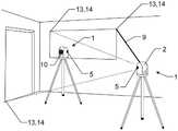
图1是来自两个不同视角的勘测装置的实施方式,其中,为了特征跟踪,将两个摄像头安装至对准部件,使得第二旋转轴线与两个摄像头的视场相交;Figure 1 is an embodiment of a surveying device from two different viewpoints, wherein, for feature tracking, two cameras are mounted to the alignment member such that the second axis of rotation intersects the fields of view of the two cameras;
图2是根据本发明的利用勘测装置的示例性工作流,其中,对准部件的取向是通过跟踪摄像头图像中的图像特征来确定的;Figure 2 is an exemplary workflow utilizing a surveying device in accordance with the present invention, wherein the orientation of an alignment component is determined by tracking image features in a camera image;
图3是根据本发明的利用勘测装置的另外的示例性工作流,其中,勘测装置被重定位,并在第一位置与第二位置之间执行SLAM过程以及对三个空间参考点进行校准测量以细化空间变换参数的获得;Figure 3 is a further exemplary workflow utilizing a surveying device according to the present invention, wherein the surveying device is relocated and a SLAM process is performed between a first location and a second location and calibration measurements are made to three spatial reference points To refine the acquisition of space transformation parameters;
图4是根据本发明的利用勘测装置的另外的示例性工作流,其中,专用标记用于参考从勘测装置的不同位置生成的测量点,Figure 4 is a further exemplary workflow utilizing a survey device according to the present invention, wherein dedicated markers are used to refer to measurement points generated from different locations of the survey device,
图5是由根据本发明的勘测装置生成的示例性360°全景图像,该示例性360°全景图像被合并至全圆顶全景图像(顶部)并被合并在两个拍摄图像的一侧处(底部)。Fig. 5 is an exemplary 360° panoramic image generated by a surveying device according to the present invention merged into a full dome panoramic image (top) and merged at one side of two captured images ( bottom).
具体实施方式Detailed ways
图1以两个不同的侧边视角描绘了根据本发明的勘测装置1的示例性实施方式。这里,勘测装置1被实施为具有望远镜2、支承件3和基座4的全站仪。一对鱼眼摄像头5被集成到望远镜2中,例如其中,各个摄像头5具有大于180°的视场,并且所述摄像头5中的各个摄像头与望远镜2一起旋转。FIG. 1 depicts an exemplary embodiment of a
望远镜2可以以机动方式旋转,由此支承件3附接至基座4以便可绕垂直旋转轴线6旋转,并且望远镜2附接至支承件3的两个相对的腿部件7以便可绕水平旋转轴线8旋转。The
全站仪1被配置为借助于激光束9来执行距离测量,该激光束经由望远镜2的波束出口10发射,从而限定目标轴线。在所示示例中,波束出口10也是用于接收激光束9的返回部分的波束入口。The
通过示例的方式,望远镜2经由位于望远镜2相对侧的两个轴11连接至两个相对的腿部件7,其中,摄像头5被安装在轴11的远轴向端上,并且摄像头的物镜的光轴12与水平旋转轴线8同轴。两个摄像头5结合起来提供全圆顶全景图像的获得。By way of example, the
图2示意性地描绘了根据本发明的利用勘测装置1的示例性工作流,该勘测装置在所示示例中如之前参考图1所描述的那样实施。为了借助于激光束9(未示出,参见图1)测量空间点,望远镜相对于水平旋转轴线8和垂直旋转轴线6移动,以便将激光束瞄准一个或多个不同的空间点(未示出)。在望远镜绕水平轴线和垂直轴线旋转期间,在利用鱼眼摄像头5拍摄的全景图像中跟踪点特征13。点特征13是利用特征检测器检测到的重要点(significant point),例如,边缘、角或高强度反射区。根据特征13的运动,测量取向(例如,相对于望远镜的初始取向的水平角度和垂直角度)的变化。FIG. 2 schematically depicts an exemplary workflow according to the invention using a
在触发测量后,例如,在触发通过激光束进行的光电距离测量后,待测量的空间点的坐标是根据测量的距离以及相对于望远镜的初始取向的所确定的水平角度和垂直角度的变化计算的。After triggering a measurement, e.g. after triggering an optoelectronic distance measurement by means of a laser beam, the coordinates of the point in space to be measured are calculated from the measured distance and the change in the determined horizontal and vertical angles relative to the initial orientation of the telescope of.
通过示例的方式,取向变化的确定基于“简化的”SLAM过程,其中仅计算取向角,而望远镜的位置被认为是固定的。By way of example, the determination of the orientation change is based on a "simplified" SLAM procedure, where only the orientation angle is calculated and the position of the telescope is considered fixed.
因此,不需要角度编码器或倾斜传感器来确定望远镜的取向。Therefore, no angle encoders or tilt sensors are required to determine the orientation of the telescope.
在另选设置中,摄像头数据与来自倾斜传感器和/或角度编码器的数据组合。通过示例的方式,针对两个旋转轴线6、8或仅针对旋转轴线中的一个旋转轴线,可以存在角度编码器,例如,可以存在测量水平角度的一个角度传感器,但不存在测量垂直角度的角度传感器。这样,垂直角度将基于对摄像头5的图像数据中的特征13的跟踪来确定。此外,图像数据和来自角度传感器和倾斜传感器的数据可以融合在一起,以确定望远镜的取向。In an alternative setup, the camera data is combined with data from a tilt sensor and/or an angle encoder. By way of example, there may be an angle encoder for both axes of
图3示意性地描绘了位于远离图2描绘的位置的另外的位置处的勘测装置。出于例示性目的,之前的设置仍显示在图中。由于现在勘测装置(以及因此望远镜和支承件)的位置也发生了变化,所以在新设置下,不仅望远镜2的取向而且还有所有六个自由度(三个坐标(X,Y,Z)和三个取向角)是相对于在勘测装置1的先前位置处的望远镜的先前位置和取向来确定的。再次地,这是通过在第一位置与第二位置之间执行SLAM过程来完成的。FIG. 3 schematically depicts a surveying device at a further location away from the location depicted in FIG. 2 . For illustrative purposes, the previous settings are still shown in the figure. Since the position of the surveying device (and therefore the telescope and support) is now also changed, under the new setup not only the orientation of the
可选地,在新设置下执行自动测量过程,其中,对具有已知坐标的三个空间参考点进行测量,以细化空间变换参数的获得。Optionally, an automatic measurement process is performed under the new setup, where measurements are made to three spatial reference points with known coordinates to refine the derivation of the spatial transformation parameters.
勘测装置1基于摄像头5的图像数据识别已在先前位置测量的点的子集。这里,例如,假设用于特征跟踪的空间点13也是勘测装置借助于激光束9确定准确坐标的实际测量点。因此,可以以双重方式使用这些空间点,即,作为用于特征跟踪的特征13和作为空间参考点14来细化空间变换参数的获得。The
然后,勘测装置1例如通过使用由SLAM过程提供的位置信息和自动目标搜索功能自动瞄准这些空间参考点14,并且借助于激光束9从当前位置测量这些点的坐标。然后使用这些坐标来更准确地确定支承件3在新设置下的位置和姿态。The
图4示出了另外的实施方式,其中,专用标记15用于参考从勘测装置1的不同位置生成的测量点。这些标记15的坐标在针对整个现场的公共坐标系中给出。例如,这些标记15的坐标(例如,利用高端全站仪)被一次测量。FIG. 4 shows a further embodiment in which
勘测装置1被配置为识别由摄像头5拍摄的图像中的标记15的成像视觉属性16。通过使用视觉属性16(这里是公共坐标系的水平轴和垂直轴的指示),勘测装置获得望远镜2在公共坐标系中的取向。The
通过示例的方式,仅具有重力矢量的指示以向勘测装置1提供重力矢量的参考也可能是足够的。这使得可以废弃倾斜传感器。By way of example, it may also be sufficient to have only an indication of the gravity vector to provide the
标记15的特性对于勘测装置1是已知的并且标记被固定地附接至勘测现场。可以使用目镜或使用勘测装置的光电图像拾取来执行标记的对准,其中,对准图像在移动装置(例如,平板电脑)上被显示给用户。另选地或另外地,勘测装置被配置为自动搜索、识别和测量标记15。The properties of the
为了监视施工进度,可能期望勘测施工现场多次,例如,每个月。假设标记15没有改变它们的位置和/或取向,则勘测装置1可以在不同时间在施工现场的不同位置设置,同时使用标记将测量点参考到公共坐标系中,例如,通过再次对准相同的标记。通过示例的方式,勘测装置1设有参考数据,该参考数据包括标记15在公共坐标系中的坐标。因此,通过从当前测量位置执行不同标记15的坐标测量,勘测装置1能够从该当前位置相对于公共坐标系绝对参考测量点。In order to monitor construction progress, it may be desirable to survey the construction site several times, for example, every month. Assuming the
图5示出了根据本发明的勘测装置1生成的示例性360°全景图像,该示例性360°全景图像被合并至全圆顶全景图像(顶部)并被合并在两个拍摄图像的一侧处(底部)。Figure 5 shows an exemplary 360° panorama image generated by the
通过示例的方式,该图的顶部中描绘的全景图像是通过使用两个鱼眼摄像头获得的,各个鱼眼摄像头表现出水平孔径角大于180°且垂直孔径角大于180°的视场,其中,两个摄像头被安装至望远镜,使得两个摄像头具有相反的视场。两个摄像头二者同时从勘测仪器的相同位置和取向拍摄图像。由于两个摄像头在图像的边缘区域表现出具有交叠区域的视场,因此两个摄像头的图像可以被很容易地合并,例如基于在边缘区域中发现的对应特征。By way of example, the panoramic image depicted in the top of the figure was obtained using two fisheye cameras, each exhibiting a field of view with a horizontal aperture angle greater than 180° and a vertical aperture angle greater than 180°, where, Two cameras are mounted to the telescope such that the two cameras have opposite fields of view. Both cameras take images simultaneously from the same position and orientation of the survey instrument. Since the two cameras exhibit fields of view with overlapping regions in the edge regions of the images, the images of the two cameras can be easily merged, e.g. based on corresponding features found in the edge regions.
例如,两个摄像头被安装在提供望远镜绕水平轴线的旋转的轴的远端处,例如,如图1所描绘的。另一可能性是将两个摄像头安装在望远镜的主体上,例如,以背靠背构造,其中,摄像头的视场相差180度。也可以通过仅使用一个摄像头生成全景图像。For example, two cameras are mounted at the distal end of an axis providing rotation of the telescope about a horizontal axis, eg as depicted in FIG. 1 . Another possibility is to mount the two cameras on the body of the telescope, eg in a back-to-back configuration, where the fields of view of the cameras differ by 180 degrees. Panoramic images can also be generated by using only one camera.
该图的底部描绘了相同的全景图,该全景图再次通过使用两个摄像头获得。然而,该图像仅在一侧处合并,以为观察者提供更好的概览。The bottom of the figure depicts the same panorama, again obtained using two cameras. However, the image is only merged at one side to give the observer a better overview.
尽管上文例示了本发明,但部分参考了一些优选实施方式,必须理解的是,可以对实施方式的不同特征进行多种修改和组合。所有这些修改都在所附权利要求的范围内。While the invention has been exemplified above, with reference in part to some preferred embodiments, it must be understood that various modifications and combinations of different features of the embodiments may be made. All such modifications are within the scope of the appended claims.
Claims (15)
Translated fromChineseApplications Claiming Priority (2)
| Application Number | Priority Date | Filing Date | Title |
|---|---|---|---|
| EP21175013.8AEP4092379B1 (en) | 2021-05-20 | 2021-05-20 | Surveying device with image evaluator for determining a spatial pose of the target axis |
| EP21175013.8 | 2021-05-20 |
Publications (2)
| Publication Number | Publication Date |
|---|---|
| CN115371544Atrue CN115371544A (en) | 2022-11-22 |
| CN115371544B CN115371544B (en) | 2025-07-29 |
Family
ID=76034544
Family Applications (1)
| Application Number | Title | Priority Date | Filing Date |
|---|---|---|---|
| CN202210507133.2AActiveCN115371544B (en) | 2021-05-20 | 2022-05-11 | Surveying device with image estimator for determining the spatial pose of a target axis |
Country Status (3)
| Country | Link |
|---|---|
| US (1) | US12277727B2 (en) |
| EP (1) | EP4092379B1 (en) |
| CN (1) | CN115371544B (en) |
Families Citing this family (1)
| Publication number | Priority date | Publication date | Assignee | Title |
|---|---|---|---|---|
| EP4092379B1 (en)* | 2021-05-20 | 2025-04-30 | Hexagon Technology Center GmbH | Surveying device with image evaluator for determining a spatial pose of the target axis |
Citations (8)
| Publication number | Priority date | Publication date | Assignee | Title |
|---|---|---|---|---|
| JP2010128610A (en)* | 2008-11-25 | 2010-06-10 | Fujitsu Ten Ltd | Drive recorder |
| US9014903B1 (en)* | 2012-05-22 | 2015-04-21 | Google Inc. | Determination of object heading based on point cloud |
| US20150130928A1 (en)* | 2013-11-12 | 2015-05-14 | Trimble Navigation Limited | Point-to-point measurements using a handheld device |
| CN105637413A (en)* | 2013-08-21 | 2016-06-01 | 奥林巴斯株式会社 | Imaging device, imaging method, and program |
| CN106979773A (en)* | 2015-11-03 | 2017-07-25 | 莱卡地球系统公开股份有限公司 | For the surface mapping equipment for the 3D coordinates for determining surface |
| EP3584533A1 (en)* | 2018-06-19 | 2019-12-25 | Apodius GmbH | Coordinate measurement system |
| CN110850429A (en)* | 2018-08-20 | 2020-02-28 | 莱卡地球系统公开股份有限公司 | Survey device for automatically training locked object or person to track target based on camera |
| CN111521161A (en)* | 2019-02-05 | 2020-08-11 | 莱卡地球系统公开股份有限公司 | Surveying apparatus comprising an event camera |
Family Cites Families (14)
| Publication number | Priority date | Publication date | Assignee | Title |
|---|---|---|---|---|
| US8379929B2 (en)* | 2009-01-08 | 2013-02-19 | Trimble Navigation Limited | Methods and apparatus for performing angular measurements |
| EP2397816A1 (en)* | 2010-06-18 | 2011-12-21 | Leica Geosystems AG | Method for verifying a surveying instrument's external orientation |
| US9285481B2 (en)* | 2012-08-20 | 2016-03-15 | Macdonald, Dettwiler And Associates Inc. | Wearable object locator and imaging system |
| US9476695B2 (en)* | 2013-07-03 | 2016-10-25 | Faro Technologies, Inc. | Laser tracker that cooperates with a remote camera bar and coordinate measurement device |
| EP3228982B1 (en)* | 2014-05-05 | 2025-01-22 | Hexagon Technology Center GmbH | Surveying system |
| US9506744B2 (en)* | 2014-12-16 | 2016-11-29 | Faro Technologies, Inc. | Triangulation scanner and camera for augmented reality |
| KR20170091913A (en)* | 2016-02-02 | 2017-08-10 | 삼성전자주식회사 | Method and apparatus for providing video service |
| AU2018230677B2 (en)* | 2017-03-06 | 2021-02-04 | Innovative Signal Analysis, Inc. | Target detection and mapping |
| US10365656B2 (en)* | 2017-11-22 | 2019-07-30 | Locus Robotics Corp. | Robot charger docking localization |
| US10645291B1 (en)* | 2018-04-26 | 2020-05-05 | General Atomics Aeronautical Systems, Inc. | Systems and methods to mitigate adverse jitter effects in mobile imaging |
| EP3696498B1 (en)* | 2019-02-15 | 2025-04-09 | Trimble Jena GmbH | Surveying instrument and method of calibrating a survey instrument |
| EP3783385A1 (en)* | 2019-08-23 | 2021-02-24 | Leica Geosystems AG | Combined point cloud generation using a stationary laser scanner and a mobile scanner |
| EP3926297B1 (en)* | 2020-06-16 | 2025-07-30 | Trimble Inc. | Scanning surveying system |
| EP4092379B1 (en)* | 2021-05-20 | 2025-04-30 | Hexagon Technology Center GmbH | Surveying device with image evaluator for determining a spatial pose of the target axis |
- 2021
- 2021-05-20EPEP21175013.8Apatent/EP4092379B1/enactiveActive
- 2022
- 2022-05-11CNCN202210507133.2Apatent/CN115371544B/enactiveActive
- 2022-05-20USUS17/750,156patent/US12277727B2/enactiveActive
Patent Citations (8)
| Publication number | Priority date | Publication date | Assignee | Title |
|---|---|---|---|---|
| JP2010128610A (en)* | 2008-11-25 | 2010-06-10 | Fujitsu Ten Ltd | Drive recorder |
| US9014903B1 (en)* | 2012-05-22 | 2015-04-21 | Google Inc. | Determination of object heading based on point cloud |
| CN105637413A (en)* | 2013-08-21 | 2016-06-01 | 奥林巴斯株式会社 | Imaging device, imaging method, and program |
| US20150130928A1 (en)* | 2013-11-12 | 2015-05-14 | Trimble Navigation Limited | Point-to-point measurements using a handheld device |
| CN106979773A (en)* | 2015-11-03 | 2017-07-25 | 莱卡地球系统公开股份有限公司 | For the surface mapping equipment for the 3D coordinates for determining surface |
| EP3584533A1 (en)* | 2018-06-19 | 2019-12-25 | Apodius GmbH | Coordinate measurement system |
| CN110850429A (en)* | 2018-08-20 | 2020-02-28 | 莱卡地球系统公开股份有限公司 | Survey device for automatically training locked object or person to track target based on camera |
| CN111521161A (en)* | 2019-02-05 | 2020-08-11 | 莱卡地球系统公开股份有限公司 | Surveying apparatus comprising an event camera |
Also Published As
| Publication number | Publication date |
|---|---|
| EP4092379B1 (en) | 2025-04-30 |
| US20220375122A1 (en) | 2022-11-24 |
| CN115371544B (en) | 2025-07-29 |
| EP4092379A1 (en) | 2022-11-23 |
| US12277727B2 (en) | 2025-04-15 |
Similar Documents
| Publication | Publication Date | Title |
|---|---|---|
| CN109556580B (en) | Surveying instrument, AR system and method for positioning an AR device relative to a reference frame | |
| CN114585875B (en) | Metering system | |
| US10665012B2 (en) | Augmented reality camera for use with 3D metrology equipment in forming 3D images from 2D camera images | |
| US10187567B2 (en) | Method and handheld distance measurement device for indirect distance measurement by means of image-assisted angle determination function | |
| US10162057B2 (en) | Portable distance measuring device and method for capturing relative positions | |
| US8699005B2 (en) | Indoor surveying apparatus | |
| KR101498149B1 (en) | Geodatic surveying device having automatic high-precision target point sighting functionality | |
| CN105606077B (en) | Geodetic Measuring System | |
| US9377301B2 (en) | Mobile field controller for measurement and remote control | |
| US9372265B2 (en) | Intermediate two-dimensional scanning with a three-dimensional scanner to speed registration | |
| JP6823482B2 (en) | 3D position measurement system, 3D position measurement method, and measurement module | |
| US11796682B2 (en) | Methods for geospatial positioning and portable positioning devices thereof | |
| CN104613946A (en) | Three-dimensional measuring method and surveying system | |
| US10809379B2 (en) | Three-dimensional position measuring system, three-dimensional position measuring method, and measuring module | |
| CN115371544B (en) | Surveying device with image estimator for determining the spatial pose of a target axis | |
| Wagner¹ et al. | Monitoring concepts using image assisted total stations | |
| GB2543658A (en) | Registration calculation between three-dimensional (3D) scans based on two-dimensional (2D) scan data from a 3D scanner | |
| EP4024339A1 (en) | Automatic registration of multiple measurement devices | |
| WO2016089428A1 (en) | Using a two-dimensional scanner to speed registration of three-dimensional scan data | |
| US12400347B2 (en) | Automated update of geometrical digital representation | |
| JP6954830B2 (en) | Target device, surveying method, surveying device and surveying program | |
| WO2016089429A1 (en) | Intermediate two-dimensional scanning with a three-dimensional scanner to speed registration |
Legal Events
| Date | Code | Title | Description |
|---|---|---|---|
| PB01 | Publication | ||
| PB01 | Publication | ||
| SE01 | Entry into force of request for substantive examination | ||
| SE01 | Entry into force of request for substantive examination | ||
| GR01 | Patent grant | ||
| GR01 | Patent grant |