CN115363862B - Wound dressing nursing device for debridement wound - Google Patents
Wound dressing nursing device for debridement woundDownload PDFInfo
- Publication number
- CN115363862B CN115363862BCN202211306239.2ACN202211306239ACN115363862BCN 115363862 BCN115363862 BCN 115363862BCN 202211306239 ACN202211306239 ACN 202211306239ACN 115363862 BCN115363862 BCN 115363862B
- Authority
- CN
- China
- Prior art keywords
- plate
- groove
- face
- fixedly connected
- wall
- Prior art date
- Legal status (The legal status is an assumption and is not a legal conclusion. Google has not performed a legal analysis and makes no representation as to the accuracy of the status listed.)
- Active
Links
- 238000001804debridementMethods0.000titleclaimsabstractdescription20
- 230000000474nursing effectEffects0.000titleclaimsabstractdescription6
- 230000007246mechanismEffects0.000claimsabstractdescription22
- 238000001125extrusionMethods0.000claimsabstractdescription15
- 239000000758substrateSubstances0.000claimsabstractdescription8
- 239000002390adhesive tapeSubstances0.000claimsdescription12
- 238000004804windingMethods0.000claimsdescription6
- 230000005540biological transmissionEffects0.000claimsdescription4
- 238000007765extrusion coatingMethods0.000claims3
- 230000037431insertionEffects0.000claims3
- 238000003780insertionMethods0.000claims3
- 230000000149penetrating effectEffects0.000claims1
- 206010052428WoundDiseases0.000abstractdescription58
- 208000027418Wounds and injuryDiseases0.000abstractdescription58
- 238000009434installationMethods0.000description25
- 239000002674ointmentSubstances0.000description21
- 230000000844anti-bacterial effectEffects0.000description13
- 238000010586diagramMethods0.000description10
- 230000009471actionEffects0.000description5
- 230000009286beneficial effectEffects0.000description5
- 238000009499grossingMethods0.000description5
- 239000003814drugSubstances0.000description4
- 239000000428dustSubstances0.000description4
- 206010033372Pain and discomfortDiseases0.000description3
- 244000052616bacterial pathogenSpecies0.000description3
- 241000894006BacteriaSpecies0.000description2
- MHAJPDPJQMAIIY-UHFFFAOYSA-NHydrogen peroxideChemical compoundOOMHAJPDPJQMAIIY-UHFFFAOYSA-N0.000description2
- 238000001266bandagingMethods0.000description2
- 230000001143conditioned effectEffects0.000description2
- 238000000034methodMethods0.000description2
- 238000012986modificationMethods0.000description2
- 230000004048modificationEffects0.000description2
- 230000011514reflexEffects0.000description2
- LFQSCWFLJHTTHZ-UHFFFAOYSA-NEthanolChemical compoundCCOLFQSCWFLJHTTHZ-UHFFFAOYSA-N0.000description1
- 229940124350antibacterial drugDrugs0.000description1
- 230000008859changeEffects0.000description1
- 239000011248coating agentSubstances0.000description1
- 238000000576coating methodMethods0.000description1
- 230000007812deficiencyEffects0.000description1
- 230000008569processEffects0.000description1
- 238000004659sterilization and disinfectionMethods0.000description1
- 238000006467substitution reactionMethods0.000description1
Images


Classifications
- A—HUMAN NECESSITIES
- A61—MEDICAL OR VETERINARY SCIENCE; HYGIENE
- A61F—FILTERS IMPLANTABLE INTO BLOOD VESSELS; PROSTHESES; DEVICES PROVIDING PATENCY TO, OR PREVENTING COLLAPSING OF, TUBULAR STRUCTURES OF THE BODY, e.g. STENTS; ORTHOPAEDIC, NURSING OR CONTRACEPTIVE DEVICES; FOMENTATION; TREATMENT OR PROTECTION OF EYES OR EARS; BANDAGES, DRESSINGS OR ABSORBENT PADS; FIRST-AID KITS
- A61F15/00—Auxiliary appliances for wound dressings; Dispensing containers for dressings or bandages
- A61F15/005—Bandage applicators
- A—HUMAN NECESSITIES
- A61—MEDICAL OR VETERINARY SCIENCE; HYGIENE
- A61B—DIAGNOSIS; SURGERY; IDENTIFICATION
- A61B90/00—Instruments, implements or accessories specially adapted for surgery or diagnosis and not covered by any of the groups A61B1/00 - A61B50/00, e.g. for luxation treatment or for protecting wound edges
- A61B90/10—Instruments, implements or accessories specially adapted for surgery or diagnosis and not covered by any of the groups A61B1/00 - A61B50/00, e.g. for luxation treatment or for protecting wound edges for stereotaxic surgery, e.g. frame-based stereotaxis
- A61B90/14—Fixators for body parts, e.g. skull clamps; Constructional details of fixators, e.g. pins
- A—HUMAN NECESSITIES
- A61—MEDICAL OR VETERINARY SCIENCE; HYGIENE
- A61F—FILTERS IMPLANTABLE INTO BLOOD VESSELS; PROSTHESES; DEVICES PROVIDING PATENCY TO, OR PREVENTING COLLAPSING OF, TUBULAR STRUCTURES OF THE BODY, e.g. STENTS; ORTHOPAEDIC, NURSING OR CONTRACEPTIVE DEVICES; FOMENTATION; TREATMENT OR PROTECTION OF EYES OR EARS; BANDAGES, DRESSINGS OR ABSORBENT PADS; FIRST-AID KITS
- A61F15/00—Auxiliary appliances for wound dressings; Dispensing containers for dressings or bandages
- A61F15/001—Packages or dispensers for bandages, cotton balls, drapes, dressings, gauze, gowns, sheets, sponges, swabsticks or towels
- A61F15/002—Packages or dispensers for bandages, cotton balls, drapes, dressings, gauze, gowns, sheets, sponges, swabsticks or towels dispensers for web or tape like bandages
- A—HUMAN NECESSITIES
- A61—MEDICAL OR VETERINARY SCIENCE; HYGIENE
- A61F—FILTERS IMPLANTABLE INTO BLOOD VESSELS; PROSTHESES; DEVICES PROVIDING PATENCY TO, OR PREVENTING COLLAPSING OF, TUBULAR STRUCTURES OF THE BODY, e.g. STENTS; ORTHOPAEDIC, NURSING OR CONTRACEPTIVE DEVICES; FOMENTATION; TREATMENT OR PROTECTION OF EYES OR EARS; BANDAGES, DRESSINGS OR ABSORBENT PADS; FIRST-AID KITS
- A61F15/00—Auxiliary appliances for wound dressings; Dispensing containers for dressings or bandages
- A61F15/007—Bandage winders
- B—PERFORMING OPERATIONS; TRANSPORTING
- B05—SPRAYING OR ATOMISING IN GENERAL; APPLYING FLUENT MATERIALS TO SURFACES, IN GENERAL
- B05C—APPARATUS FOR APPLYING FLUENT MATERIALS TO SURFACES, IN GENERAL
- B05C11/00—Component parts, details or accessories not specifically provided for in groups B05C1/00 - B05C9/00
- B05C11/02—Apparatus for spreading or distributing liquids or other fluent materials already applied to a surface ; Controlling means therefor; Control of the thickness of a coating by spreading or distributing liquids or other fluent materials already applied to the coated surface
- B05C11/023—Apparatus for spreading or distributing liquids or other fluent materials already applied to a surface
- B05C11/025—Apparatus for spreading or distributing liquids or other fluent materials already applied to a surface with an essentially cylindrical body, e.g. roll or rod
- B—PERFORMING OPERATIONS; TRANSPORTING
- B05—SPRAYING OR ATOMISING IN GENERAL; APPLYING FLUENT MATERIALS TO SURFACES, IN GENERAL
- B05C—APPARATUS FOR APPLYING FLUENT MATERIALS TO SURFACES, IN GENERAL
- B05C5/00—Apparatus in which liquid or other fluent material is projected, poured or allowed to flow on to the surface of the work
- B05C5/02—Apparatus in which liquid or other fluent material is projected, poured or allowed to flow on to the surface of the work the liquid or other fluent material being discharged through an outlet orifice by pressure, e.g. from an outlet device in contact or almost in contact, with the work
- B05C5/0245—Apparatus in which liquid or other fluent material is projected, poured or allowed to flow on to the surface of the work the liquid or other fluent material being discharged through an outlet orifice by pressure, e.g. from an outlet device in contact or almost in contact, with the work for applying liquid or other fluent material to a moving work of indefinite length, e.g. to a moving web
- B05C5/025—Apparatus in which liquid or other fluent material is projected, poured or allowed to flow on to the surface of the work the liquid or other fluent material being discharged through an outlet orifice by pressure, e.g. from an outlet device in contact or almost in contact, with the work for applying liquid or other fluent material to a moving work of indefinite length, e.g. to a moving web only at particular part of the work
Landscapes
- Health & Medical Sciences (AREA)
- Life Sciences & Earth Sciences (AREA)
- General Health & Medical Sciences (AREA)
- Biomedical Technology (AREA)
- Heart & Thoracic Surgery (AREA)
- Engineering & Computer Science (AREA)
- Animal Behavior & Ethology (AREA)
- Public Health (AREA)
- Veterinary Medicine (AREA)
- Vascular Medicine (AREA)
- Epidemiology (AREA)
- Surgery (AREA)
- Nuclear Medicine, Radiotherapy & Molecular Imaging (AREA)
- Oral & Maxillofacial Surgery (AREA)
- Pathology (AREA)
- Neurosurgery (AREA)
- Medical Informatics (AREA)
- Molecular Biology (AREA)
- Materials For Medical Uses (AREA)
Abstract
Description
Translated fromChinese技术领域technical field
本发明涉及伤口护理技术领域,具体为用于清创伤口的伤口敷料护理装置。The invention relates to the technical field of wound care, in particular to a wound dressing care device for wound debridement.
背景技术Background technique
创口伤在处理时,首先选择过氧化氢、酒精及一些药酒进行消毒处理,再用碘伏涂于伤口周围皮肤,之后涂上抗菌软膏用纱布进行包扎,而对于一些创伤面积较大的则需要二次换药敷上抗菌软膏进行包扎。When treating wounds, first choose hydrogen peroxide, alcohol and some medicinal wine for disinfection, then apply iodophor to the skin around the wound, and then apply antibacterial ointment and bandage with gauze. Antibacterial ointment was applied for the second dressing change.
现有的对腿部或手臂进行清创伤口的敷料护理时,若直接对伤口处进行挤药涂抹,由于涂抹的动作会触碰伤口导致患者出现疼痛以及肢体出现条件反射进行应激的现象,从而造成了患者的不适,以及在护理后包扎纱布时通常为撕开胶布粘贴在纱布与皮肤处进行固定,不便快速地让胶布对纱布的两端进行缠绕粘贴,容易导致胶带失去黏性造成纱布脱落,使得患者伤口直接暴露在空气中沾染灰尘或细菌的现象。When the existing dressing care for wound debridement on legs or arms, if the wound is directly squeezed and smeared, the action of smearing will touch the wound, causing pain in the patient and conditioned reflexes in the limbs to stress, Thereby causing the patient's discomfort, and when dressing the gauze after nursing, the adhesive tape is usually torn off and pasted on the gauze and the skin for fixation. Shedding, making the patient's wound directly exposed to dust or bacteria in the air.
因此提出了用于清创伤口的伤口敷料护理装置。Wound dressing care devices for debridement of wounds have therefore been proposed.
发明内容Contents of the invention
(一)解决的技术问题(1) Solved technical problems
针对现有技术的不足,本发明提供了用于清创伤口的伤口敷料护理装置,解决了现有的对腿部或手臂进行清创伤口的敷料护理时,若直接对伤口处进行挤药涂抹,由于涂抹的动作会触碰伤口导致患者出现疼痛以及肢体出现条件反射进行应激的现象,从而造成了患者的不适,以及在护理后包扎纱布时通常为撕开胶布粘贴在纱布与皮肤处进行固定,不便快速地让胶布对纱布的两端进行缠绕粘贴,容易导致胶带失去黏性造成纱布脱落,使得患者伤口直接暴露在空气中沾染灰尘或细菌的现象的问题。Aiming at the deficiencies in the prior art, the present invention provides a wound dressing care device for debridement of wounds, which solves the problem of directly extruding medicine on the wound when performing wound debridement care on legs or arms. , because the action of smearing will touch the wound, causing pain in the patient and conditioned reflexes in the limbs to stress, which causes discomfort to the patient, and when bandaging the gauze after nursing, it is usually torn off the adhesive tape and pasted on the gauze and the skin. Fixed, it is inconvenient to quickly wrap the tape around the two ends of the gauze, which will easily cause the tape to lose its viscosity and cause the gauze to fall off, so that the patient's wound is directly exposed to dust or bacteria in the air.
(二)技术方案(2) Technical solutions
为实现以上目的,本发明通过以下技术方案予以实现:用于清创伤口的伤口敷料护理装置,包括基板、L型板,所述基板的上端面固定连接有L型板,所述L型板的上端面安装有自动挤压涂抹机构,所述基板的上端面通过凹槽滑动连接有竖板,所述竖板的右侧壁安装有胶带缠绕机构,所述基板的上端面对称安装有限位夹持机构;In order to achieve the above object, the present invention is achieved through the following technical solutions: a wound dressing care device for wound debridement, comprising a base plate and an L-shaped plate, the upper end surface of the base plate is fixedly connected with an L-shaped plate, and the L-shaped plate The upper end surface of the base plate is equipped with an automatic extrusion and smearing mechanism, the upper end surface of the base plate is slidably connected with a vertical plate through a groove, the right side wall of the vertical plate is equipped with a tape winding mechanism, and the upper end surface of the base plate is symmetrically installed with a limited Bit clamping mechanism;
所述自动挤压涂抹机构包括立板,所述立板的前端面固定连接有套环,所述立板的前端面贯穿开设有斜槽,所述L型板的前端面通过安装板转动连接有插柱,所述插柱的外壁插接有纱布卷,所述插柱的右端固定连接有凸轮槽盘,所述凸轮槽盘的槽壁滑动连接有转动轴,所述转动轴的外壁转动连接有L型杆,所述斜槽的槽壁滑动连接有活动轴,所述活动轴的前端面转动连接有挤压辊,所述L型杆的前端面固定连接有侧板,所述侧板的前端面贯穿开设有波浪槽,所述波浪槽的槽壁滑动连接有滑动杆,所述滑动杆的前端面固定连接有T型板,所述T型板的下端面转动连接有抹平辊。The automatic extrusion and smearing mechanism includes a vertical plate, the front end of the vertical plate is fixedly connected with a collar, the front end of the vertical plate is provided with a chute, and the front end of the L-shaped plate is rotatably connected by a mounting plate. There is a plug, the outer wall of the plug is inserted with a gauze roll, the right end of the plug is fixedly connected with a cam groove plate, the groove wall of the cam groove plate is slidably connected with a rotating shaft, and the outer wall of the rotating shaft rotates An L-shaped rod is connected, the groove wall of the chute is slidably connected with a movable shaft, the front end of the movable shaft is rotatably connected with a squeeze roller, the front end of the L-shaped rod is fixedly connected with a side plate, and the side plate The front end surface of the plate is provided with a wave groove, the groove wall of the wave groove is slidably connected with a sliding rod, the front end surface of the sliding rod is fixedly connected with a T-shaped plate, and the lower end surface of the T-shaped plate is rotatably connected with a smoothing rod. roll.
优选的,所述凸轮槽盘开设有滑槽,所述滑槽的深度小于凸轮槽盘的厚度,所述L型杆的前端面通过滑槽与活动轴后端面滑动连接,所述L型杆的内侧壁与L型板的右侧壁滑动连接。Preferably, the cam groove plate is provided with a chute, the depth of the chute is smaller than the thickness of the cam groove plate, the front end surface of the L-shaped rod is slidably connected with the rear end surface of the movable shaft through the chute, and the L-shaped rod The inner side wall of the L-shaped plate is slidingly connected with the right side wall of the L-shaped plate.
优选的,所述T型板与L型板的上腔顶滑动连接,所述L型板的上端面安装有漏斗套。Preferably, the T-shaped plate is slidably connected to the top of the upper cavity of the L-shaped plate, and a funnel sleeve is installed on the upper end surface of the L-shaped plate.
优选的,所述胶带缠绕机构包括齿圈、固定柱、胶布卷、安装轴、绳索,所述竖板的右侧壁转动连接有齿圈,所述齿圈的右侧壁固定连接有固定柱,所述固定柱的外壁插接有胶布卷,所述竖板左侧壁贯穿转动连接有安装轴,所述安装轴的外壁缠绕有绳索。Preferably, the adhesive tape winding mechanism includes a gear ring, a fixed column, a tape roll, an installation shaft, and a rope, the right side wall of the riser is rotatably connected to the gear ring, and the right side wall of the ring gear is fixedly connected to the fixed column , the outer wall of the fixed column is plugged with a tape roll, the left side wall of the riser is connected to the installation shaft through rotation, and the outer wall of the installation shaft is wound with a rope.
优选的,所述绳索远离安装轴的一端固定连接有拉环,所述安装轴的右端固定连接有小齿轮,所述小齿轮与齿圈相啮合,所述安装轴的外壁缠绕有发条弹簧,所述发条弹簧远离安装轴的一端与竖板右侧壁固定连接。Preferably, the end of the rope away from the installation shaft is fixedly connected with a pull ring, the right end of the installation shaft is fixedly connected with a pinion, the pinion is meshed with the ring gear, and the outer wall of the installation shaft is wound with a clockwork spring , the end of the clockwork spring away from the installation shaft is fixedly connected to the right side wall of the riser.
优选的,所述限位夹持机构包括弧形板、销轴、弧形环,所述基板的上端面对称固定连接有弧形板,所述弧形板的内壁通过销轴转动连接有弧形环。Preferably, the position-limiting clamping mechanism includes an arc-shaped plate, a pin shaft, and an arc-shaped ring. The upper end surface of the base plate is symmetrically and fixedly connected with an arc-shaped plate, and the inner wall of the arc-shaped plate is rotatably connected with an arc-shaped plate through a pin shaft. arc ring.
优选的,销轴的左端固定连接有蜗轮,所述基板的凹槽内对称转动连接有螺旋槽柱,所述螺旋槽柱的上端面转动连接有蜗杆,所述蜗杆与蜗轮相啮合。Preferably, the left end of the pin shaft is fixedly connected with a worm wheel, the groove of the base plate is symmetrically rotatably connected with a spiral groove column, and the upper end surface of the spiral groove column is rotatably connected with a worm, and the worm meshes with the worm wheel.
优选的,所述基板的上端面固定连接有凸板,所述凸板的前端面通过滑槽滑动连接有滑板,所述螺旋槽柱的槽壁滑动连接有滑轴,所述滑轴的右端与滑板侧壁固定连接,所述凸板的前端面通过滑槽滑动连接有移动板,所述滑槽的槽壁通过弹簧伸缩杆与移动板右侧壁固定连接。Preferably, the upper end surface of the base plate is fixedly connected with a convex plate, the front end surface of the convex plate is slidably connected with a sliding plate through a chute, the groove wall of the spiral groove column is slidably connected with a sliding shaft, and the right end of the sliding shaft It is fixedly connected with the side wall of the sliding plate, and the front end of the convex plate is slidably connected with the moving plate through a chute, and the groove wall of the chute is fixedly connected with the right side wall of the moving plate through a spring telescopic rod.
优选的,所述移动板的左侧壁铰接有连杆,所述连杆的上端面与滑板侧壁铰接,所述竖板的左侧壁固定连接有导杆,所述导杆与移动板的右侧壁相贴合,两个所述螺旋槽柱靠近下部的外壁通过皮带传动连接。Preferably, the left side wall of the moving board is hinged with a connecting rod, the upper end surface of the connecting rod is hinged with the side wall of the slide plate, and the left side wall of the vertical board is fixedly connected with a guide rod, and the guide rod is connected with the moving board The right side wall of the two spiral groove columns is connected by a belt drive near the lower outer wall.
(三)有益效果(3) Beneficial effects
本发明所提供的用于清创伤口的伤口敷料护理装置,具备以下有益效果:The wound dressing care device for wound debridement provided by the present invention has the following beneficial effects:
1、该用于清创伤口的伤口敷料护理装置在使用时,首先手握纱布卷的一端向前拉动带动插柱转动,插柱转动时会带动凸轮槽盘发生转动,凸轮槽盘转动时由于槽为凸轮形状能够让转动轴顺着槽壁向下移动,进而顶动L型杆拉伸两个活动轴与挤压辊同时下降,活动轴下降时会在斜槽内滑动并带动两个挤压辊相互靠近,可以将抗菌软膏管的外壁进行挤压,能够让膏体落在受到拉扯的纱布上,便能在拉纱布进行剪断包扎时可以自动让抗菌软膏挤在纱布上,从而便于后续的敷料包扎,避免伤口长时间暴露在空气中感染病菌,之后通过再拉扯一截纱布用于第二层包扎,能够让插柱重新转动带动凸轮槽盘转动复位成初始状态,使得L型杆向上滑动拉动挤压辊复位,有利于后续对下一个患者进行挤压抗菌药管敷料的操作;1. When the wound dressing care device for wound debridement is in use, first hold one end of the gauze roll and pull it forward to drive the post to rotate. When the post rotates, it will drive the cam groove plate to rotate. The groove is in the shape of a cam, which allows the rotating shaft to move down along the groove wall, and then pushes the L-shaped rod to stretch the two movable shafts and the extrusion rollers to descend at the same time. When the movable shaft descends, it will slide in the chute and drive the two extrusion rollers. The pressure rollers are close to each other, which can squeeze the outer wall of the antibacterial ointment tube, allowing the ointment to fall on the pulled gauze, so that the antibacterial ointment can be automatically squeezed on the gauze when the gauze is pulled for cutting and bandaging, so that it is convenient for follow-up Dressing to prevent the wound from being exposed to the air for a long time to infect germs, and then pull a piece of gauze for the second layer of dressing, so that the post can be rotated again to drive the cam groove plate to rotate and reset to the initial state, making the L-shaped rod upward Sliding and pulling the squeeze roller to reset is beneficial to the subsequent operation of squeezing the antibacterial tube dressing for the next patient;
2、该用于清创伤口的伤口敷料护理装置能实现当L型杆下降会带动前部的侧板下降,侧板下降时由于波浪槽的作用会通过挤压滑动杆拉动T型板进行左右滑动,使得抹平辊左右移动能够对纱布上部的药膏进行均匀地抹平,省去了人工敷料进行抹药的麻烦,不仅可以避免直接在伤口处抹药造成患者疼痛不适的现象,还能防止药膏直接挤出敷在伤口处导致药膏较多或者一些位置没有抹上的情况;2. The wound dressing care device for wound debridement can realize that when the L-shaped rod descends, it will drive the front side plate to descend. When the side plate descends, due to the action of the wave groove, it will pull the T-shaped plate to move left and right by squeezing the sliding rod. Sliding, so that the smoothing roller moves left and right to evenly smooth the ointment on the upper part of the gauze, saving the trouble of applying artificial dressings, not only avoiding the pain and discomfort caused by directly applying medicine to the wound, but also preventing The ointment is directly squeezed out and applied to the wound, resulting in more ointment or some positions are not applied;
3、该用于清创伤口的伤口敷料护理装置能实现在敷上带有抗菌药膏的纱布后,可以移动滑动竖板移动至需要缠绕胶带的纱布处,只需要将胶布卷的一头贴在皮肤上,之后手握拉环向上拉动绳索拉长使安装轴转动并带动发条弹簧收缩,安装轴转动时会带动小齿轮转动啮合齿圈转动一圈,便会同步带动胶布卷转动一圈,能够让胶带缠绕一圈在纱布的外壁,之后切断缠绕一周的胶带再松动拉环,此时发条弹簧复位回弹便会带动安装轴反转将绳索收回,也会重新带动胶布卷回归原位,之后可以继续移动竖板移动对敷上纱布的另一端进行重复操作,让胶带再缠绕一周,其操作简单能够快速地对伤口处的纱布进行缠绕胶带,提高了对护理伤口进行包扎纱布的效率,并且通过缠绕一周胶带的方式能够让纱布与皮肤固定得更紧,避免胶带黏性失去使纱布脱落造成伤口暴露沾染灰尘的情况;3. The wound dressing care device for wound debridement can realize that after the gauze with antibacterial ointment is applied, the sliding vertical plate can be moved to the gauze where the tape needs to be wrapped, and only one end of the tape roll needs to be attached to the skin Then hold the pull ring and pull the rope upwards to lengthen the installation shaft to rotate and drive the mainspring to shrink. When the installation shaft rotates, it will drive the pinion to rotate and the meshing ring to rotate for one turn, which will synchronously drive the tape roll to rotate for one turn. Let the tape wrap around the outer wall of the gauze, then cut off the wrapped tape and loosen the pull ring. At this time, the clockwork spring returns and rebounds, which will drive the installation shaft to reverse and retract the rope, and will also drive the tape roll back to its original position. After that, you can continue to move the vertical board to move the other end of the gauze and repeat the operation, so that the tape can be wound for another week. The operation is simple and can quickly wrap the tape on the gauze at the wound, which improves the efficiency of wrapping the gauze on the wound. And by wrapping the tape for a week, the gauze and the skin can be fixed more tightly, so as to avoid the situation where the tape loses its viscosity and the gauze falls off, causing the wound to be exposed and contaminated with dust;
4、该用于清创伤口的伤口敷料护理装置能实现在对伤口进行敷料护理前,先滑动竖板向右移动使导杆不再抵触移动板,此时原本受到挤压产生压缩的弹簧伸缩杆复位回弹拉动移动板向右滑动,进而带动连杆向下发生转动,使得连杆拉伸滑板向下滑动,会让滑轴挤压左侧的螺旋槽柱发生转动,由于两个螺旋槽柱通过皮带传动连接,能够在左侧的螺旋槽柱转动的同时带动右侧的螺旋槽柱同步转动,便会让上部的蜗杆啮合蜗轮转动,从而带动销轴与弧形环向下转动贴合在患者的腿部或手臂上,可以快速便捷的对患者清创的手臂或腿部进行夹持约束,避免在敷料时患者感到疼痛肢体出现反抗影响敷料进度的现象,从而加快了对患者清创伤口敷料的进度,也不需要医护人员用手按压制动。4. The wound dressing care device for wound debridement can realize that before performing dressing care on the wound, first slide the vertical plate to move to the right so that the guide rod no longer touches the moving plate. At this time, the compressed spring originally compressed expands. The rod resets and rebounds to pull the moving plate to slide to the right, which in turn drives the connecting rod to rotate downward, causing the connecting rod to stretch the sliding plate to slide downward, which will cause the sliding shaft to press the left spiral groove column to rotate. Due to the two spiral grooves The column is connected by a belt drive, which can drive the spiral groove column on the right side to rotate synchronously while the spiral groove column on the left rotates, so that the upper worm meshes with the worm wheel to rotate, thereby driving the pin shaft and the arc ring to rotate downward and fit together On the patient's leg or arm, the patient's debridement arm or leg can be clamped and restrained quickly and conveniently, so as to avoid the phenomenon that the patient feels pain and the limbs resist and affect the progress of the dressing during dressing, thus speeding up the debridement of the patient The progress of wound dressing does not require medical staff to press the brake with their hands.
附图说明Description of drawings
图1为本发明立体结构示意图;Fig. 1 is a schematic diagram of the three-dimensional structure of the present invention;
图2为本发明图1中A区域放大结构示意图;Fig. 2 is the schematic diagram of enlarged structure of A region in Fig. 1 of the present invention;
图3为本发明图1中B区域放大结构示意图;Fig. 3 is the schematic diagram of enlarged structure of area B in Fig. 1 of the present invention;
图4为本发明活动轴与L型杆安装结构示意图;Fig. 4 is a schematic diagram of the installation structure of the movable shaft and the L-shaped rod of the present invention;
图5为本发明L型板与漏斗套安装结构示意图;Fig. 5 is a schematic diagram of the installation structure of the L-shaped plate and the funnel cover of the present invention;
图6为本发明L型杆与侧板安装结构示意图;Fig. 6 is a schematic diagram of the installation structure of the L-shaped bar and the side plate of the present invention;
图7为本发明6中C区域放大结构示意图;Fig. 7 is a schematic diagram of the enlarged structure of area C in the
图8为本发明基板局部剖切结构示意图;8 is a schematic diagram of a partial cutaway structure of the substrate of the present invention;
图9为本发明后视整体安装结构示意图;Fig. 9 is a schematic diagram of the rear view overall installation structure of the present invention;
图10为本发明小齿轮与齿圈啮合安装结构示意图。Fig. 10 is a schematic diagram of the meshing installation structure of the pinion gear and the ring gear of the present invention.
图中:1、基板;2、L型板;3、自动挤压涂抹机构;31、立板;32、套环;33、斜槽;34、插柱;35、纱布卷;36、凸轮槽盘;37、转动轴;38、L型杆;39、活动轴;310、挤压辊;311、侧板;312、波浪槽;313、滑动杆;314、T型板;315、抹平辊;316、漏斗套;In the figure: 1. base plate; 2. L-shaped plate; 3. automatic extrusion and coating mechanism; 31. vertical plate; 32. collar; 33. chute; 34. post; 35. gauze roll; 36. cam groove Disk; 37, rotating shaft; 38, L-shaped rod; 39, movable shaft; 310, squeezing roller; 311, side plate; 312, wave groove; 313, sliding rod; 314, T-shaped plate; ; 316, funnel cover;
4、竖板;5、胶带缠绕机构;51、齿圈;52、固定柱;53、胶布卷;54、安装轴;55、绳索;56、拉环;57、小齿轮;58、发条弹簧;4. Riser; 5. Tape winding mechanism; 51. Ring gear; 52. Fixed column; 53. Tape roll; 54. Installation shaft; 55. Rope; 56. Pull ring; 57. Pinion; 58. Clockwork spring ;
6、限位夹持机构;61、弧形板;62、销轴;63、弧形环;64、蜗轮;65、螺旋槽柱;66、蜗杆;67、凸板;68、滑板;69、滑轴;610、连杆;611、移动板;612、弹簧伸缩杆;613、导杆;614、皮带。6. Limit clamping mechanism; 61. Arc-shaped plate; 62. Pin shaft; 63. Arc-shaped ring; 64. Worm wheel; 65. Spiral groove column; 66. Worm screw; 67. Convex plate; Slide shaft; 610, connecting rod; 611, moving plate; 612, spring expansion rod; 613, guide rod; 614, belt.
具体实施方式detailed description
下面将结合本发明实施例中的附图,对本发明实施例中的技术方案进行清楚、完整地描述,显然,所描述的实施例仅仅是本发明一部分实施例,而不是全部的实施例。基于本发明中的实施例,本领域普通技术人员在没有做出创造性劳动前提下所获得的所有其他实施例,都属于本发明保护的范围。The following will clearly and completely describe the technical solutions in the embodiments of the present invention with reference to the accompanying drawings in the embodiments of the present invention. Obviously, the described embodiments are only some, not all, embodiments of the present invention. Based on the embodiments of the present invention, all other embodiments obtained by persons of ordinary skill in the art without making creative efforts belong to the protection scope of the present invention.
本发明提供技术方案:The invention provides technical solutions:
实施例一Embodiment one
请参阅图1、图2、图4至图6和图9,用于清创伤口的伤口敷料护理装置,包括基板1、L型板2,基板1的上端面固定连接有L型板2,L型板2的上端面安装有自动挤压涂抹机构3,基板1的上端面通过凹槽滑动连接有竖板4,竖板4的右侧壁安装有胶带缠绕机构5,基板1的上端面对称安装有限位夹持机构6;Referring to Fig. 1, Fig. 2, Fig. 4 to Fig. 6 and Fig. 9, the wound dressing care device for wound debridement includes a
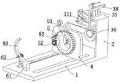
L型板2的上端面安装有自动挤压涂抹机构3,自动挤压涂抹机构3包括立板31、插柱34,立板31的前端面固定连接有套环32,立板31的前端面贯穿开设有斜槽33,L型板2的前端面通过安装板转动连接有插柱34,插柱34的外壁插接有纱布卷35,插柱34的右端固定连接有凸轮槽盘36,凸轮槽盘36的槽壁滑动连接有转动轴37,转动轴37的外壁转动连接有L型杆38,斜槽33的槽壁滑动连接有活动轴39,活动轴39的前端面转动连接有挤压辊310,L型杆38的前端面固定连接有侧板311,手握纱布卷35的一端向前拉动带动插柱34转动,插柱34转动时会带动凸轮槽盘36发生转动,凸轮槽盘36转动时由于槽为凸轮形状能够让转动轴37顺着槽壁向下移动,进而顶动L型杆38拉伸两个活动轴39与挤压辊310同时下降,活动轴39下降时会在斜槽33内滑动并带动两个挤压辊310相互靠近,可以将抗菌软膏管的外壁进行挤压,能够让膏体落在受到拉扯的纱布上,便能在拉纱布进行剪断包扎时可以自动让抗菌软膏挤在纱布上,从而便于后续的敷料包扎,避免伤口长时间暴露在空气中感染病菌,之后通过再拉扯一截纱布用于第二层包扎,能够让插柱34重新转动带动凸轮槽盘36转动复位成初始状态,使得L型杆38向上滑动拉动挤压辊310复位,有利于后续对下一个患者进行挤压抗菌药管敷料的操作。The upper surface of the L-shaped
实施例二Embodiment two
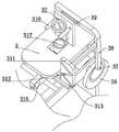
请参阅图1、图2、图4至图6和图9,侧板311的前端面贯穿开设有波浪槽312,波浪槽312的槽壁滑动连接有滑动杆313,滑动杆313的前端面固定连接有T型板314,T型板314的下端面转动连接有抹平辊315,凸轮槽盘36开设有滑槽,滑槽的深度小于凸轮槽盘36的厚度,L型杆38的前端面通过滑槽与活动轴39后端面滑动连接,L型杆38的内侧壁与L型板2的右侧壁滑动连接,T型板314与L型板2的上腔顶滑动连接,L型板2的上端面安装有漏斗套316,由于波浪槽312的作用会通过挤压滑动杆313拉动T型板314进行左右滑动,使得抹平辊315左右移动能够对纱布上部的药膏进行均匀地抹平,可以避免直接在伤口处抹药造成患者疼痛不适的现象。Please refer to Fig. 1, Fig. 2, Fig. 4 to Fig. 6 and Fig. 9, the front end surface of the
实施例三Embodiment three
请参阅图3和图9和图10,胶带缠绕机构5包括齿圈51、固定柱52、胶布卷53、安装轴54、绳索55,竖板4的右侧壁转动连接有齿圈51,齿圈51的右侧壁固定连接有固定柱52,固定柱52的外壁插接有胶布卷53,竖板4左侧壁贯穿转动连接有安装轴54,安装轴54的外壁缠绕有绳索55,远离安装轴54的一端固定连接有拉环56,安装轴54的右端固定连接有小齿轮57,小齿轮57与齿圈51相啮合,安装轴54的外壁缠绕有发条弹簧58,发条弹簧58远离安装轴54的一端与竖板4右侧壁固定连接,发条弹簧58在复位回弹时便会带动安装轴54反转将绳索55收回,也会重新带动胶布卷53回归原位,便于重新将胶布贴在纱布的另一端进行缠绕。Please refer to Fig. 3 and Fig. 9 and Fig. 10, tape winding mechanism 5 comprises ring gear 51, fixed column 52, adhesive tape roll 53, installation shaft 54, rope 55, and the right side wall of riser 4 is connected with ring gear 51 in rotation, and tooth The right side wall of the ring 51 is fixedly connected with a fixed column 52, the outer wall of the fixed column 52 is plugged with an adhesive tape roll 53, the left side wall of the riser 4 is connected with a mounting shaft 54 for rotation, and the outer wall of the mounting shaft 54 is wound with a rope 55, away from One end of the installation shaft 54 is fixedly connected with a pull ring 56, and the right end of the installation shaft 54 is fixedly connected with a pinion 57, the pinion 57 is meshed with the ring gear 51, and the outer wall of the installation shaft 54 is wound with a clockwork spring 58, and the clockwork spring 58 One end far away from the installation shaft 54 is fixedly connected with the right side wall of the vertical plate 4, and the clockwork spring 58 will drive the installation shaft 54 to reverse to retract the rope 55 when it resets and rebounds, and will also drive the adhesive tape roll 53 to return to its original position, which is convenient Re-attach the tape to the other end of the gauze and wrap it around.
实施例四Embodiment Four
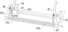
请参阅图3、图5至图9,限位夹持机构6包括弧形板61、销轴62、弧形环63,基板1的上端面对称固定连接有弧形板61,弧形板61的内壁通过销轴62转动连接有弧形环63,销轴62的左端固定连接有蜗轮64,基板1的凹槽内对称转动连接有螺旋槽柱65,螺旋槽柱65的上端面转动连接有蜗杆66,蜗杆66与蜗轮64相啮合,蜗杆66啮合蜗轮64转动,从而带动销轴62与弧形环63向下转动贴合在患者的腿部或手臂上,可以快速便捷的对患者清创的手臂或腿部进行夹持约束,基板1的上端面固定连接有凸板67,凸板67的前端面通过滑槽滑动连接有滑板68,螺旋槽柱65的槽壁滑动连接有滑轴69,滑轴69的右端与滑板68侧壁固定连接,凸板67的前端面通过滑槽滑动连接有移动板611,滑槽的槽壁通过弹簧伸缩杆612与移动板611右侧壁固定连接,移动板611的左侧壁铰接有连杆610,连杆610的上端面与滑板68侧壁铰接,竖板4的左侧壁固定连接有导杆613,导杆613与移动板611的右侧壁相贴合,两个螺旋槽柱65靠近下部的外壁通过皮带614传动连接,由于两个螺旋槽柱65通过皮带614传动连接,能够在左侧的螺旋槽柱65转动的同时带动右侧的螺旋槽柱65同步转动。Referring to Fig. 3, Fig. 5 to Fig. 9, the
工作原理,初始状态下让患者将有伤口的腿部或者手臂放在弧形板61的上部,将清创伤口后需要用的抗菌软膏放在套环32与漏斗套316的内部,首先手握纱布卷35的一端向前拉动带动插柱34转动,插柱34转动时会带动凸轮槽盘36发生转动,凸轮槽盘36转动时由于槽为凸轮形状能够让转动轴37顺着槽壁向下移动,进而顶动L型杆38拉伸两个活动轴39与挤压辊310同时下降,活动轴39下降时会在斜槽33内滑动并带动两个挤压辊310相互靠近,可以将抗菌软膏管的外壁进行挤压,能够让膏体落在受到拉扯的纱布上,便能在拉纱布进行剪断包扎时可以自动让抗菌软膏挤在纱布上,从而便于后续的敷料包扎,避免伤口长时间暴露在空气中感染病菌,之后通过再拉扯一截纱布用于第二层包扎,拉扯纱布时会带动插柱34再次转动带动凸轮槽盘36转动一周复位成初始状态,使得L型杆38向上滑动拉动挤压辊310复位,有利于后续对下一个患者进行挤压抗菌药管敷料的操作;Working principle, in the initial state, let the patient put the wounded leg or arm on the upper part of the arc-shaped
当L型杆38下降会带动前部的侧板311下降,侧板311下降时由于波浪槽312的作用会通过挤压滑动杆313拉动T型板314进行左右滑动,使得抹平辊315左右移动能够对纱布上部的药膏进行均匀地抹平,省去了人工敷料进行抹药的麻烦,不仅可以避免直接在伤口处抹药造成患者疼痛不适的现象,还能防止药膏直接挤出敷在伤口处导致药膏较多或者一些位置没有抹上的情况;When the L-shaped
在敷上带有抗菌药膏的纱布后,可以移动滑动竖板4移动至需要缠绕胶带的纱布处,只需要将胶布卷53的一头贴在皮肤上,之后手握拉环56向上拉动绳索55拉长使安装轴54转动并带动发条弹簧58收缩,安装轴54转动时会带动小齿轮57转动啮合齿圈51转动一圈,便会同步带动胶布卷53转动一圈,能够让胶带缠绕一圈在纱布的外壁,之后切断缠绕一周的胶带再松动拉环56,此时发条弹簧58复位回弹便会带动安装轴54反转将绳索55收回,也会重新带动胶布卷53回归原位,之后可以继续移动竖板4移动对敷上纱布的另一端进行重复操作,让胶带再缠绕一周,其操作简单能够快速地对伤口处的纱布进行缠绕胶带,提高了对护理伤口进行包扎纱布的效率,并且通过缠绕一周胶带的方式能够让纱布与皮肤固定得更紧,避免胶带黏性失去使纱布脱落造成伤口暴露沾染灰尘的情况;After applying the gauze with antibacterial ointment, you can move the sliding
在对伤口进行敷料护理前,先滑动竖板4向右移动使导杆613不再抵触移动板611,此时原本受到挤压产生压缩的弹簧伸缩杆612复位回弹拉动移动板611向右滑动,进而带动连杆610向下发生转动,使得连杆610拉伸滑板68向下滑动,会让滑轴69挤压左侧的螺旋槽柱65发生转动,由于两个螺旋槽柱65通过皮带614传动连接,能够在左侧的螺旋槽柱65转动的同时带动右侧的螺旋槽柱65同步转动,便会让上部的蜗杆66啮合蜗轮64转动,从而带动销轴62与弧形环63向下转动贴合在患者的腿部或手臂上,可以快速便捷的对患者清创的手臂或腿部进行夹持约束,避免在敷料时患者感到疼痛肢体出现反抗影响敷料进度的现象,从而加快了对患者清创伤口敷料的进度,也不需要医护人员用手按压制动。Before dressing the wound, slide the
尽管已经示出和描述了本发明的实施例,对于本领域的普通技术人员而言,可以理解在不脱离本发明的原理和精神的情况下可以对这些实施例进行多种变化、修改、替换和变型,本发明的范围由所附权利要求及其等同物限定。Although the embodiments of the present invention have been shown and described, those skilled in the art can understand that various changes, modifications and substitutions can be made to these embodiments without departing from the principle and spirit of the present invention. and modifications, the scope of the invention is defined by the appended claims and their equivalents.
Claims (3)
Priority Applications (1)
| Application Number | Priority Date | Filing Date | Title |
|---|---|---|---|
| CN202211306239.2ACN115363862B (en) | 2022-10-25 | 2022-10-25 | Wound dressing nursing device for debridement wound |
Applications Claiming Priority (1)
| Application Number | Priority Date | Filing Date | Title |
|---|---|---|---|
| CN202211306239.2ACN115363862B (en) | 2022-10-25 | 2022-10-25 | Wound dressing nursing device for debridement wound |
Publications (2)
| Publication Number | Publication Date |
|---|---|
| CN115363862A CN115363862A (en) | 2022-11-22 |
| CN115363862Btrue CN115363862B (en) | 2022-12-27 |
Family
ID=84073681
Family Applications (1)
| Application Number | Title | Priority Date | Filing Date |
|---|---|---|---|
| CN202211306239.2AActiveCN115363862B (en) | 2022-10-25 | 2022-10-25 | Wound dressing nursing device for debridement wound |
Country Status (1)
| Country | Link |
|---|---|
| CN (1) | CN115363862B (en) |
Families Citing this family (1)
| Publication number | Priority date | Publication date | Assignee | Title |
|---|---|---|---|---|
| CN119523738B (en)* | 2025-01-07 | 2025-07-18 | 中国人民解放军总医院第一医学中心 | Surgical incision protection device for thoracic surgery patient |
Citations (3)
| Publication number | Priority date | Publication date | Assignee | Title |
|---|---|---|---|---|
| CN111437107A (en)* | 2020-04-02 | 2020-07-24 | 枣庄市妇幼保健院 | Auxiliary tray for dressing change of caesarean wound |
| CN213489821U (en)* | 2020-10-22 | 2021-06-22 | 连云港市第二人民医院(连云港市临床肿瘤研究所) | Dressing coating equipment for wound care |
| CN114366451A (en)* | 2021-12-26 | 2022-04-19 | 三维医疗科技江苏股份有限公司 | Convenient surgical disinfection binding device with high automation degree |
Family Cites Families (5)
| Publication number | Priority date | Publication date | Assignee | Title |
|---|---|---|---|---|
| DE102006012898A1 (en)* | 2006-03-13 | 2007-09-20 | Ing. Erich Pfeiffer Gmbh | Discharge device for a flowable medium |
| ES2847599T3 (en)* | 2014-09-29 | 2021-08-03 | Dermira Inc | Device for dispensing a drug |
| CN105250007A (en)* | 2015-10-27 | 2016-01-20 | 李诗贤 | Binding type pressing hemostasis device for department of cardiology |
| CN112675417B (en)* | 2021-01-08 | 2022-09-09 | 山东卓辰科技服务有限公司 | Special ointment obliterator for infectious skin diseases |
| CN114522028B (en)* | 2022-01-28 | 2022-08-12 | 中国人民解放军总医院京中医疗区 | Adaptive surrounding type swing type field emergency hemostasis bandaging device |
- 2022
- 2022-10-25CNCN202211306239.2Apatent/CN115363862B/enactiveActive
Patent Citations (3)
| Publication number | Priority date | Publication date | Assignee | Title |
|---|---|---|---|---|
| CN111437107A (en)* | 2020-04-02 | 2020-07-24 | 枣庄市妇幼保健院 | Auxiliary tray for dressing change of caesarean wound |
| CN213489821U (en)* | 2020-10-22 | 2021-06-22 | 连云港市第二人民医院(连云港市临床肿瘤研究所) | Dressing coating equipment for wound care |
| CN114366451A (en)* | 2021-12-26 | 2022-04-19 | 三维医疗科技江苏股份有限公司 | Convenient surgical disinfection binding device with high automation degree |
Also Published As
| Publication number | Publication date |
|---|---|
| CN115363862A (en) | 2022-11-22 |
Similar Documents
| Publication | Publication Date | Title |
|---|---|---|
| CN109966100B (en) | Automatic spiral wrapping type dressing change device | |
| CN115363862B (en) | Wound dressing nursing device for debridement wound | |
| CN110074933B (en) | Nursing is with frame of changing dressings | |
| CN113303977B (en) | A shank is wrapped device for medical care | |
| CN207575183U (en) | Seepage-proof liquid pressurization application | |
| CN115737331A (en) | Multifunctional combined bracket for dressing change of wound | |
| CN110269997A (en) | A kind of drainage tube fixing device | |
| CN114098886A (en) | Fixing device for axillary skin pressure dressing after axillary odor operation | |
| CN115317775A (en) | Skin disinfection device for marrow puncture nursing | |
| CN212854342U (en) | Heart nursing external application medicine fixing device | |
| CN115429544A (en) | An emergency limb dressing device | |
| CN211798209U (en) | Adjustable applicator for nursing in burn department | |
| CN221751989U (en) | Auxiliary drug delivery device for ear treatment | |
| CN220344656U (en) | A kind of dressing support device for emergency department nursing | |
| CN221712501U (en) | A liquid dressing flattening device | |
| CN220385300U (en) | Trauma binding device | |
| CN221751236U (en) | Auxiliary mechanism for surgical wound dressing change | |
| CN111671485A (en) | Convenient finger cuff type nail unit pressurizing device | |
| CN218923519U (en) | Applicator for fixing drainage tube | |
| CN208591300U (en) | A kind of nasal cavity cleaning device | |
| CN221654951U (en) | A rapid dispensing device for medical and health care | |
| CN218075466U (en) | Wound cleaning device is used in emergency department's nursing | |
| CN105581907B (en) | Folding drug thread making device | |
| CN214260346U (en) | Applicator for skin venereal disease | |
| CN219397921U (en) | wound pressure care device |
Legal Events
| Date | Code | Title | Description |
|---|---|---|---|
| PB01 | Publication | ||
| PB01 | Publication | ||
| SE01 | Entry into force of request for substantive examination | ||
| SE01 | Entry into force of request for substantive examination | ||
| GR01 | Patent grant | ||
| GR01 | Patent grant |