CN115363648B - Flexible surgical instrument, flexible instrument and instrument conveying unit thereof - Google Patents
Flexible surgical instrument, flexible instrument and instrument conveying unit thereofDownload PDFInfo
- Publication number
- CN115363648B CN115363648BCN202211117678.9ACN202211117678ACN115363648BCN 115363648 BCN115363648 BCN 115363648BCN 202211117678 ACN202211117678 ACN 202211117678ACN 115363648 BCN115363648 BCN 115363648B
- Authority
- CN
- China
- Prior art keywords
- instrument
- driving
- flexible
- drive
- terminal
- Prior art date
- Legal status (The legal status is an assumption and is not a legal conclusion. Google has not performed a legal analysis and makes no representation as to the accuracy of the status listed.)
- Active
Links
Images


Classifications
- A—HUMAN NECESSITIES
- A61—MEDICAL OR VETERINARY SCIENCE; HYGIENE
- A61B—DIAGNOSIS; SURGERY; IDENTIFICATION
- A61B17/00—Surgical instruments, devices or methods
- A61B17/00234—Surgical instruments, devices or methods for minimally invasive surgery
- A—HUMAN NECESSITIES
- A61—MEDICAL OR VETERINARY SCIENCE; HYGIENE
- A61B—DIAGNOSIS; SURGERY; IDENTIFICATION
- A61B17/00—Surgical instruments, devices or methods
- A61B17/00234—Surgical instruments, devices or methods for minimally invasive surgery
- A61B2017/00292—Surgical instruments, devices or methods for minimally invasive surgery mounted on or guided by flexible, e.g. catheter-like, means
- A61B2017/003—Steerable
- A61B2017/00305—Constructional details of the flexible means
- A—HUMAN NECESSITIES
- A61—MEDICAL OR VETERINARY SCIENCE; HYGIENE
- A61B—DIAGNOSIS; SURGERY; IDENTIFICATION
- A61B17/00—Surgical instruments, devices or methods
- A61B17/00234—Surgical instruments, devices or methods for minimally invasive surgery
- A61B2017/00292—Surgical instruments, devices or methods for minimally invasive surgery mounted on or guided by flexible, e.g. catheter-like, means
- A61B2017/003—Steerable
- A61B2017/00318—Steering mechanisms
- A—HUMAN NECESSITIES
- A61—MEDICAL OR VETERINARY SCIENCE; HYGIENE
- A61B—DIAGNOSIS; SURGERY; IDENTIFICATION
- A61B17/00—Surgical instruments, devices or methods
- A61B17/00234—Surgical instruments, devices or methods for minimally invasive surgery
- A61B2017/00292—Surgical instruments, devices or methods for minimally invasive surgery mounted on or guided by flexible, e.g. catheter-like, means
- A61B2017/0034—Surgical instruments, devices or methods for minimally invasive surgery mounted on or guided by flexible, e.g. catheter-like, means adapted to be inserted through a working channel of an endoscope
Landscapes
- Health & Medical Sciences (AREA)
- Life Sciences & Earth Sciences (AREA)
- Surgery (AREA)
- Heart & Thoracic Surgery (AREA)
- Engineering & Computer Science (AREA)
- Biomedical Technology (AREA)
- Nuclear Medicine, Radiotherapy & Molecular Imaging (AREA)
- Medical Informatics (AREA)
- Molecular Biology (AREA)
- Animal Behavior & Ethology (AREA)
- General Health & Medical Sciences (AREA)
- Public Health (AREA)
- Veterinary Medicine (AREA)
- Surgical Instruments (AREA)
Abstract
Translated fromChinese
Description
Translated fromChinese技术领域technical field
本发明涉及医疗器械领域技术领域,具体涉及一种柔性手术器械、柔性器械及其器械输送单元。The invention relates to the technical field of medical instruments, in particular to a flexible surgical instrument, a flexible instrument and an instrument delivery unit thereof.
背景技术Background technique
消化系统、泌尿系统、呼吸系统等自然腔道疾病是常见重大慢性病,如胃癌、食管癌、大肠癌、膀胱癌、肺癌等疾病发病率和死亡率高,严重危害人体健康。以软式内镜配合相关手术器械进行诊断和治疗已成为主流治疗手段,具有创伤小、出血量小,并发症发生率低的特点。Digestive system, urinary system, respiratory system and other natural orifice diseases are common major chronic diseases, such as gastric cancer, esophageal cancer, colorectal cancer, bladder cancer, lung cancer and other diseases with high morbidity and mortality, which seriously endanger human health. Diagnosis and treatment with flexible endoscopes combined with relevant surgical instruments has become the mainstream treatment method, which has the characteristics of less trauma, less bleeding, and lower incidence of complications.
众所周知,与常规大切口手术不同的是,经人体腔道介入手术的操作空间常常狭小,通常需要依赖柔性器械进行诊疗操作。现有的柔性器械种类丰富,例如但不限于夹钳类、电凝电切类、注射类、引导类等,能够满足狭窄环境下的不同操作需求。目前的手术器械大多基于人工操作设计,为满足腔道介入需求,现有柔性器械设计为柔性细长类器械,使用过程中需要医护人员配合、操作复杂;另外,柔性细长的器械容易与污物接触,存在污染风险,且在器械收回过程中也会存在交叉感染的可能。As we all know, different from conventional large incision surgery, the operation space of interventional surgery through human body cavity is often narrow, and it usually needs to rely on flexible instruments for diagnosis and treatment operations. Existing flexible instruments are rich in types, such as but not limited to clamps, electrocoagulation and electrocution, injections, guides, etc., which can meet different operating requirements in narrow environments. Most of the current surgical instruments are designed based on manual operation. In order to meet the needs of cavity intervention, the existing flexible instruments are designed as flexible and slender instruments, which require the cooperation of medical staff and complicated operation during use; There is a risk of contamination, and there is also the possibility of cross-infection during the retraction of the device.
有鉴于此,亟待针对柔性手术器械进行优化设计,以克服上述缺陷。In view of this, it is urgent to optimize the design of flexible surgical instruments to overcome the above defects.
发明内容Contents of the invention
本申请的目的在于提供一种柔性手术器械、柔性器械及其器械输送单元,通过优化配置能够实现柔性器械的执行器单元本体的有效收纳,在满足规避交叉污染的功能要求基础上,结构设计合理可靠。The purpose of this application is to provide a flexible surgical instrument, a flexible instrument and its instrument delivery unit. Through optimal configuration, the effective storage of the actuator unit body of the flexible instrument can be realized. On the basis of meeting the functional requirements of avoiding cross-contamination, the structural design is reasonable reliable.
本申请实施例提供的器械输送单元,用于具有柔性本体的执行器单元的输送和收纳,包括外壳和器械储存器,所述外壳具有内部容纳空间且其侧壁开设有器械出口,至少部分所述器械储存器内置于所述外壳中,且可相对于所述外壳转动和轴向移动;所述器械储存器的外周表面设置有螺旋容纳槽,以缠绕收纳执行器单元的柔性本体。The instrument delivery unit provided in the embodiment of the present application is used for delivery and storage of an actuator unit with a flexible body, and includes a housing and an instrument storage. The instrument storage is built in the shell, and can rotate and move axially relative to the shell; the outer peripheral surface of the instrument storage is provided with a spiral accommodation groove to wrap around and accommodate the flexible body of the actuator unit.
可选地,所述外壳为一端敞口的圆筒状,所述器械储存器的一端置于所述外壳中,另一端配置有用于与器械驱动装置适配的输送驱动接口。Optionally, the housing is in the shape of a cylinder with one end open, one end of the instrument storage is placed in the housing, and the other end is configured with a delivery driving interface adapted to an instrument driving device.
可选地,所述器械出口外周的所述外壳表面固定设置有护管,且所述外壳包括固定部。Optionally, a protective tube is fixedly arranged on the outer surface of the outer shell of the instrument outlet, and the outer shell includes a fixed portion.
本申请实施例还提供一种柔性器械,包括如前所述的器械输送单元,还包括执行器单元和传动单元,其中,所述执行器单元包括执行器和柔性本体,所述柔性本体包括内外嵌套设置的驱动丝和套管,所述驱动丝的远端配置有所述执行器;所述传动单元与所述器械输送单元的器械储存器相连,所述传动单元配置有用于与器械驱动装置适配的输送驱动接口,以带动所述器械储存器相对于所述外壳转动和轴向移动。The embodiment of the present application also provides a flexible instrument, including the aforementioned instrument delivery unit, and also includes an actuator unit and a transmission unit, wherein the actuator unit includes an actuator and a flexible body, and the flexible body includes an inner and outer The driving wire and the cannula are nested, and the distal end of the driving wire is configured with the actuator; the transmission unit is connected with the instrument storage of the instrument delivery unit, and the transmission unit is configured for driving with the instrument A delivery drive interface adapted to the device to drive the instrument storage to rotate and move axially relative to the housing.
可选地,所述传动单元还配置有用于与器械驱动装置适配的执行驱动接口,以带动所述执行器单元的驱动丝运动。。Optionally, the transmission unit is further configured with an actuating drive interface adapted to the instrument driving device, so as to drive the driving wire of the actuator unit to move. .
可选地,所述传动单元包括与所述器械储存器固定连接的传动基板,和设置在所述传动基板上的执行传动组件和旋转传动组件;所述输送驱动接口位于在所述传动基板上,所述执行驱动接口包括第一执行驱动接口和第二执行驱动接口,所述执行传动组件与所述第一执行驱动接口适配,以推出或收回所述驱动丝,所述旋转传动组件与所述第二执行驱动接口适配,以扭转所述驱动丝。Optionally, the transmission unit includes a transmission substrate fixedly connected to the instrument storage, and an execution transmission assembly and a rotation transmission assembly arranged on the transmission substrate; the delivery drive interface is located on the transmission substrate , the actuating driving interface includes a first actuating driving interface and a second actuating driving interface, the actuating transmission assembly is adapted to the first actuating driving interface to push out or retract the driving wire, and the rotating transmission assembly is connected to the first actuating driving interface The second actuator drive interface is adapted to twist the drive wire.
可选地,所述执行传动组件包括牵引件和第一驱动轴,所述第一驱动轴插装设置在所述传动基板上,并可通过所述第一执行驱动接口与器械驱动装置传动连接;所述牵引件与第一驱动轴连接,所述驱动丝的近端与所述牵引件相连接,并配置为:所述驱动丝可在所述牵引件的带动下沿预定轨迹推出或收回,且所述驱动丝相对于所述牵引件具有转动自由度。Optionally, the actuating drive assembly includes a traction member and a first drive shaft, the first drive shaft is inserted on the drive base plate, and can be drive-connected with the instrument drive device through the first actuating drive interface The traction member is connected to the first driving shaft, the proximal end of the driving wire is connected to the traction member, and is configured such that the driving wire can be pushed out or retracted along a predetermined trajectory driven by the traction member , and the driving wire has a rotational degree of freedom relative to the pulling member.
可选地,所述牵引件的外周表面嵌装设置有第一端子,所述第一端子包括第四贯通孔;所述驱动丝穿装在所述第一端子的第四贯通孔中,所述驱动丝的本体上设置有两个限位块,且分别位于所述第一端子的第四贯通孔两端侧;所述驱动丝与所述第一端子的第四贯通孔之间具有径向间隙,且每个所述限位块的尺寸大于所述第四贯通孔的尺寸。Optionally, a first terminal is embedded on the outer peripheral surface of the pulling member, and the first terminal includes a fourth through hole; the driving wire is installed in the fourth through hole of the first terminal, so The body of the driving wire is provided with two limit blocks, which are respectively located at both ends of the fourth through hole of the first terminal; there is a diameter between the driving wire and the fourth through hole of the first terminal. To the gap, and the size of each of the limiting blocks is larger than the size of the fourth through hole.
可选地,所述传动基板上固定设置有第一约束件,所述第一约束件上开设有可容纳驱动丝的约束腔,以带动所述驱动丝沿预定轨迹推出或收回。Optionally, a first constraining member is fixedly disposed on the transmission substrate, and a constraining cavity capable of accommodating a driving wire is opened on the first constraining member, so as to drive the driving wire to push out or retract along a predetermined trajectory.
可选地,所述第一约束件及其上开设的约束腔均呈弧状,且所述第一约束件包括顺次连接的导向段和保持段,所述导向段具有与所述牵引件的圆弧状外周表面相对设置的圆弧状内壁,且所述导向段的内壁上的约束腔为开放腔道,所述保持段上的约束腔为封闭腔道。Optionally, the first constraining member and the constraining cavity provided thereon are both arc-shaped, and the first constraining member includes a guiding segment and a holding segment connected in sequence, and the guiding segment has a connection with the traction member. The circular-arc-shaped outer peripheral surface is opposite to the circular-arc-shaped inner wall, and the confinement cavity on the inner wall of the guide section is an open cavity, and the confinement cavity on the holding section is a closed cavity.
可选地,所述执行传动组件包括第一驱动轴、相啮合的锥齿轮组、第一端子和丝杆,所述锥齿轮组的主动齿轮与所述第一驱动轴连接,所述丝杆与所述锥齿轮组的被动齿轮连接;所述第一端子的一端夹持固定所述驱动丝的近端,所述第一端子的另一端配置有与所述丝杆适配的螺母,以通过第一端子带动驱动丝实现推出或收回。Optionally, the actuating transmission assembly includes a first drive shaft, an engaged bevel gear set, a first terminal and a lead screw, the driving gear of the bevel gear set is connected to the first drive shaft, and the lead screw It is connected with the driven gear of the bevel gear set; one end of the first terminal clamps and fixes the proximal end of the driving wire, and the other end of the first terminal is equipped with a nut adapted to the screw rod, so as to The driving wire is driven by the first terminal to realize pushing out or retracting.
可选地,所述旋转传动组件包括旋转轴、第二端子、锥齿轮组和第二驱动轴,所述第二驱动轴插装设置在所述传动基板上,并可通过所述第二执行驱动接口与器械驱动装置传动连接;所述锥齿轮组的主动轮与所述第二驱动轴连接,所述旋转轴与所述锥齿轮组的被动轮连接;所述驱动丝与所述第二端子固定,所述第二端子设置在所述旋转轴上,并配置为:所述第二端子可在所述旋转轴的带动下转动,且所述第二端子相对于所述旋转轴具有沿驱动丝的牵拉方向滑动的自由度。Optionally, the rotation transmission assembly includes a rotation shaft, a second terminal, a bevel gear set, and a second drive shaft, the second drive shaft is inserted on the transmission substrate, and can be The driving interface is connected with the driving device of the instrument; the driving wheel of the bevel gear set is connected with the second drive shaft, and the rotating shaft is connected with the driven wheel of the bevel gear set; the driving wire is connected with the second drive shaft. The terminal is fixed, the second terminal is arranged on the rotating shaft, and the configuration is that: the second terminal can be rotated under the driving of the rotating shaft, and the second terminal has an edge relative to the rotating shaft The degree of freedom to slide in the pulling direction of the actuating wire.
可选地,所述第二端子嵌装在所述旋转轴的中部安装孔中,且两者具体相适配的矩形截面,所述驱动丝可经由所述安装孔延伸至第一约束件的约束腔中。Optionally, the second terminal is embedded in the installation hole in the middle of the rotating shaft, and the two have a specific matching rectangular cross-section, and the driving wire can extend to the first restraining member through the installation hole. in the confined cavity.
可选地,所述传动基板上固定设置有第二约束件,沿所述旋转轴的轴向,所述第二约束件的一端与所述第一约束件的保持段端部相对设置,且所述旋转轴的两侧轴端分别与所述第二约束件和所述第一约束件枢接。Optionally, a second constraint is fixedly arranged on the transmission substrate, and one end of the second constraint is arranged opposite to the end of the holding section of the first constraint along the axial direction of the rotating shaft, and The shaft ends on both sides of the rotating shaft are respectively pivotally connected to the second restraint part and the first restraint part.
可选地,所述第二约束件上开设有第三贯通孔,所述第二约束件的第三贯通孔的孔径与所述执行器单元的套管尺寸适配,以固定所述套管的管端;所述器械储存器上开设有通过口,所述执行器单元的柔性本体通过所述器械储存器的通过口延伸过渡至其外表面的螺旋容纳槽中。Optionally, a third through hole is opened on the second restraint member, and the diameter of the third through hole of the second restraint member is adapted to the size of the sleeve of the actuator unit, so as to fix the sleeve The end of the pipe; the instrument storage is provided with a passage port, and the flexible body of the actuator unit extends and transitions into the spiral accommodation groove on the outer surface through the passage port of the instrument storage.
本发明还提供一种柔性手术器械,包括柔性器械和可输出驱动力至所述柔性器械的器械驱动装置,所述柔性器械采用如前所述的柔性器械。The present invention also provides a flexible surgical instrument, including a flexible instrument and an instrument driving device capable of outputting a driving force to the flexible instrument, and the flexible instrument adopts the flexible instrument as described above.
与现有技术相比,本发明针对具有柔性本体的执行器单元提出了收纳输送实现方案。具体地,该器械输送单元的外壳具有内部容纳空间且其侧壁开设有器械出口,器械储存器的外周表面设置有螺旋容纳槽,以缠绕收纳执行器单元的柔性本体,且器械储存器可相对于外壳转动和轴向移动。应用本方案,具有下述有益技术效果:Compared with the prior art, the present invention proposes a storage and delivery solution for the actuator unit with a flexible body. Specifically, the outer casing of the instrument delivery unit has an internal accommodation space and an instrument outlet is opened on its side wall, and the outer peripheral surface of the instrument storage is provided with a spiral accommodation groove to wrap around the flexible body of the actuator unit, and the instrument storage can be relatively The housing rotates and moves axially. Applying this scheme has the following beneficial technical effects:
首先,随着器械储存器的转动,缠绕收纳于螺旋容纳槽的柔性本体可通过器械出口连续输送。执行器输送过程中,基于螺旋缠绕形变储备的弹性变形能得以释放,可有效克服进入软式内镜中形成的阻力,辅助提供良好输送能力。Firstly, with the rotation of the instrument storage, the flexible body wound and accommodated in the spiral accommodation groove can be continuously conveyed through the instrument outlet. During the delivery process of the actuator, the elastic deformation energy based on the helical winding deformation reserve is released, which can effectively overcome the resistance formed in the soft endoscope and assist in providing good delivery capacity.
其次,器械储存器反向运动,则柔性本体可收回至外壳内并螺旋缠绕在器械储存器上,一方面,对于自身刚度不高的柔性本体,本方案通过结构约束使得柔性本体有序排布,规避本体之间相互挤压和破坏;同时,执行器单元的收回及收纳不占用径向尺寸空间,结构较为紧凑合理,便于临床使用操作,可进一步解决目前柔性器械单人操作难,存在交叉感染的临床问题。Secondly, when the instrument storage moves in the opposite direction, the flexible body can be retracted into the shell and wound spirally on the instrument storage. On the one hand, for the flexible body with low rigidity itself, this scheme makes the flexible body orderly arranged through structural constraints , to avoid mutual extrusion and damage between the bodies; at the same time, the retraction and storage of the actuator unit does not occupy the radial dimension space, the structure is relatively compact and reasonable, and it is convenient for clinical use and operation. Clinical problems of infection.
第三,在本发明的可选方案中,该外壳为一端敞口的圆筒状,器械储存器的一端置于外壳中,另一端配置有用于与器械驱动装置适配的输送驱动接口。这样,通过输送驱动接口传递驱动力,可根据不同应用场景实现自动输送或收纳操作。Thirdly, in an optional solution of the present invention, the casing is in the shape of a cylinder with one end open, one end of the instrument storage is placed in the casing, and the other end is configured with a delivery drive interface adapted to the instrument drive device. In this way, the driving force is transmitted through the conveying drive interface, and automatic conveying or storage operations can be realized according to different application scenarios.
第四,在本发明的另一可选方案中,所提供的柔性器械包括传动单元,以通过执行器单元的驱动丝带动执行器相应的操作,该传动单元与器械储存器相连,且配置有用于与器械驱动装置适配的执行驱动接口,例如但不限于,可实现驱动丝的牵拉和扭转操作。Fourth, in another optional solution of the present invention, the provided flexible instrument includes a transmission unit to drive the corresponding operation of the actuator through the driving wire of the actuator unit. The transmission unit is connected with the instrument storage and is configured to be useful The actuating drive interface adapted to the instrument driving device, for example but not limited to, can realize the pulling and twisting operations of the driving wire.
第五,在本发明的又一可选方案中,执行传动组件包括牵引件和第一驱动轴,该第一驱动轴插装可通过第一执行驱动接口与器械驱动装置传动连接;牵引件与第一驱动轴连接,驱动丝的近端与牵引件相连接,并配置为:驱动丝可在牵引件的带动下沿预定轨迹推出或收回,且驱动丝相对于牵引件具有转动自由度。进一步地,旋转传动组件包括旋转轴、第二端子、锥齿轮组和第二驱动轴,该第二驱动轴可通过第二执行驱动接口与器械驱动装置传动连接;锥齿轮组的主动轮与第二驱动轴连接,旋转轴与锥齿轮组的被动轮连接;驱动丝与第二端子固定,第二端子设置在旋转轴上,并配置为:第二端子可在旋转轴的带动下转动,且第二端子相对于旋转轴具有沿驱动丝的牵拉方向滑动的自由度。如此设置,在执行传动组件的带动下,执行器单元的驱动丝推出或收回时,基于该第二端子与旋转轴之间滑动自由度,旋转传动侧无动作干涉;同样地,在旋转传动组件的带动下,执行器单元的驱动丝扭转时,基于该驱动丝近端与牵引件之间的转动自由度,执行传动侧也无动作干涉。Fifth, in another optional solution of the present invention, the actuator transmission assembly includes a traction member and a first drive shaft, and the first drive shaft can be plugged and connected to the instrument drive device through the first execution drive interface; the traction member and the The first driving shaft is connected, and the proximal end of the driving wire is connected with the traction member, and is configured such that the driving wire can be pushed out or retracted along a predetermined track driven by the traction member, and the driving wire has a degree of freedom of rotation relative to the traction member. Further, the rotation transmission assembly includes a rotation shaft, a second terminal, a bevel gear set and a second drive shaft, and the second drive shaft can be connected to the instrument drive device through a second execution drive interface; the driving wheel of the bevel gear set is connected to the first The two driving shafts are connected, and the rotating shaft is connected to the driven wheel of the bevel gear set; the driving wire is fixed to the second terminal, and the second terminal is arranged on the rotating shaft, and is configured such that the second terminal can rotate under the driving of the rotating shaft, and The second terminal has a degree of freedom to slide relative to the rotating shaft along the pulling direction of the driving wire. In this way, driven by the actuator transmission assembly, when the drive wire of the actuator unit is pushed out or retracted, based on the sliding degree of freedom between the second terminal and the rotation shaft, there is no movement interference on the rotation transmission side; similarly, when the rotation transmission assembly Driven by the drive, when the driving wire of the actuator unit is twisted, based on the degree of freedom of rotation between the proximal end of the driving wire and the traction member, there is no action interference on the actuator transmission side.
附图说明Description of drawings
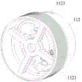
图1为本申请实施方式所述柔性器械的一种应用状态示意图;Fig. 1 is a schematic diagram of an application state of the flexible device described in the embodiment of the present application;
图2为本申请实施方式所述柔性器械的整体结构示意图;2 is a schematic diagram of the overall structure of the flexible device described in the embodiment of the present application;
图3为图2中所示柔性器械的装配爆炸图;Figure 3 is an exploded view of the assembly of the flexible device shown in Figure 2;
图4为图2中所示柔性器械局部剖切形成的示意图;Fig. 4 is a schematic diagram of a partial section of the flexible device shown in Fig. 2;
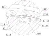
图5为本申请实施方式提供的一种执行器单元的示意图;FIG. 5 is a schematic diagram of an actuator unit provided in an embodiment of the present application;
图6为图2的A-A剖视图;Fig. 6 is A-A sectional view of Fig. 2;
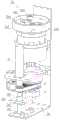
图7为本申请实施方式提供的传动单元的整体结构示意图;FIG. 7 is a schematic diagram of the overall structure of the transmission unit provided in the embodiment of the present application;
图8示出了本申请实施方式所述传动单元与器械储存器的装配关系示意图;Fig. 8 shows a schematic diagram of the assembly relationship between the transmission unit and the instrument storage according to the embodiment of the present application;
图9为另一视角形成的传动单元与器械储存器的装配关系示意图;Fig. 9 is a schematic diagram of the assembly relationship between the transmission unit and the instrument storage formed from another perspective;
图10为本申请实施方式所述执行传动组件的装配关系示意图;Fig. 10 is a schematic diagram of the assembly relationship of the actuating transmission assembly described in the embodiment of the present application;
图11为图6的Ⅰ部放大示意图;Figure 11 is an enlarged schematic view of part I of Figure 6;
图12为本申请实施方式提供的另一种执行传动组件的示意图;Fig. 12 is a schematic diagram of another execution transmission assembly provided by the embodiment of the present application;
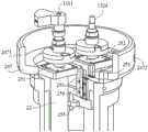
图13为本申请实施方式所述旋转传动组件的装配关系示意图;Fig. 13 is a schematic diagram of the assembly relationship of the rotation transmission assembly described in the embodiment of the present application;
图14为图6的Ⅱ部放大示意图;Fig. 14 is an enlarged schematic diagram of part II of Fig. 6;
图15为本申请实施方式中所述电源和信号源引入路径示意图;FIG. 15 is a schematic diagram of the introduction path of the power supply and the signal source described in the embodiment of the present application;
图16为本申请实施方式所述器械驱动装置的内部构成示意图;Fig. 16 is a schematic diagram of the internal structure of the instrument driving device according to the embodiment of the present application;
图17为图16中所示器械驱动装置侧的连接机构示意图Fig. 17 is a schematic diagram of the connection mechanism on the side of the instrument driving device shown in Fig. 16
图18为本申请实施方式所述驱动基板与器械储存器的组装关系示意图;Fig. 18 is a schematic diagram of the assembly relationship between the drive substrate and the instrument storage according to the embodiment of the present application;
图19为图17的B-B局部剖视图;Fig. 19 is a partial sectional view of B-B of Fig. 17;
图20为本申请实施方式中所述第一主动传动盘和第二主动传动盘的组装关系示意图;Fig. 20 is a schematic diagram of the assembly relationship between the first driving disc and the second driving disc in the embodiment of the present application;
图21为本申请实施方式中所述传动基板与传动单元的组装关系示意图;Fig. 21 is a schematic diagram of the assembly relationship between the transmission substrate and the transmission unit in the embodiment of the present application;
图22为本申请实施方式中所述第一驱动件的传动关系示意图;Fig. 22 is a schematic diagram of the transmission relationship of the first driving member in the embodiment of the present application;
图23为图16的轴向剖视图。Fig. 23 is an axial sectional view of Fig. 16 .
图中:In the picture:
柔性器械10、器械输送单元11、外壳111、器械出口1111、插口1112、器械储存器112、螺旋容纳槽1121、通过口1122、卡口1123、护管113、执行器单元12、驱动丝121、限位块1211、执行器122、套管123、传动单元13、执行传动组件131、第一驱动轴1311、第一端子1312、第四贯通孔13121、牵引件1313、安装槽13131、第一约束件1315、约束腔13151、第一内部通道13152、锥齿轮组1311a、第一端子1312a、丝杆1313a、旋转传动组件132、旋转轴1321、安装孔13211、第二端子1322、锥齿轮组1323、第二驱动轴1324、第二约束件1325、第三贯通孔13251、第二内部通道13252、传动基板133、卡槽1331、第一被动传动盘134、第一凹部1341、第二被动传动盘135、第二凹部1351、对接单元14、电接口141、水接口142、引导管15、信号发生器161、信号接收器162、安装检测组件17;
器械驱动装置20、第一驱动部件21、第二驱动部件22、第三驱动部件23、接口部件24、驱动基板241、第一贯通孔2411、第二贯通孔2412、第一主动传动盘242、第一凸部2421、第二主动传动盘243、第二凸部2431、卡扣244、勾头部2441、引导面2442、按钮245、复位弹簧246、套筒247、遮挡段2471、穿装孔2472、连接套248、第一法兰251、第二法兰252、滑动支架253、滑轨254、复位件255、丝杆261、螺母262、主动带轮263、从动带轮264、输出轴265、键2651、第一轴套266、键槽2661、连接件267、轴承固定座268、推力轴承2681、轴承269、罩壳27、侧壁271、固定盘272、第二轴套273、导向套274。The
具体实施方式Detailed ways
为了使本领域的技术人员更好地理解本发明的技术方案,下面结合附图和具体实施例对本发明作进一步的详细说明。In order to enable those skilled in the art to better understand the technical solutions of the present invention, the present invention will be further described in detail below in conjunction with the accompanying drawings and specific embodiments.
不失一般性,本实施方式提供一种柔性手术器械,以有效解决较长细软器械操作复杂,不易收纳用容易污染的问题。请参见图1,该图为本申请实施方式所述柔性操作器械的整体结构示意图。Without loss of generality, this embodiment provides a flexible surgical instrument to effectively solve the problems of complicated operation, difficult storage and easy contamination of long and thin instruments. Please refer to FIG. 1 , which is a schematic diagram of the overall structure of the flexible operating instrument according to the embodiment of the present application.
该柔性手术器械包括柔性器械10和器械驱动装置20,其中,柔性器械10中配置有用于诊疗和辅助诊疗的执行器单元12,器械驱动装置20可提供驱动力至柔性器械10,以实现柔性器械的输送操作和执行器的旋转或开闭等操作。The flexible surgical instrument includes a
请一并参见图2和图3,其中,图2为本申请实施方式所述柔性器械的示意图,图3为图2中所示柔性器械10的装配爆炸图。Please refer to FIG. 2 and FIG. 3 together, wherein FIG. 2 is a schematic diagram of the flexible device according to an embodiment of the present application, and FIG. 3 is an exploded assembly view of the
该柔性器械10包括器械输送单元11、内置于器械输送单元11中的执行器单元12和用于传递执行器运动驱动力的传动单元13。The
其中,器械输送单元11包括外壳111和器械储存器112,在传动单元13的带动下,器械储存器112可相对于外壳111转动;本实施方案中,外壳111为一端敞口的圆筒状,且部分器械储存器112置于外壳111中,组装完成后,外壳111保持相对固定的状态。在其他具体实现中,器械储存器也可完全置于外壳中(图中未示出)。Wherein, the
其中,执行器单元12的柔性本体(驱动丝121及套管123)缠绕在器械储存器112外周,且可经由外壳111侧壁开设的器械出口1111伸出;这里,器械出口1111外侧设置有护管113,该护管固定在外壳111上,以便伸出外壳111的执行器单元12保护稳定的姿态。随着器械储存器112的转动,执行器单元12的柔性本体通过器械出口1111连续输送;同理,器械储存器112反向运动时,则柔性本体可收回至外壳内并缠绕在器械储存器112上,实现执行器单元12的收回及收纳。具体来说,非使用状态下的外壳111和器械储存器112形成相对封闭的空间,用于柔性器械本体的收纳。Wherein, the flexible body (driving
为了执行器单元12的柔性本体能够有序缠绕排布,器械储存器112的外周表面可设置有螺旋容纳槽1121,请一并参见图4,该图为图2中所示柔性器械局部剖切形成的示意图。收回至外壳内的执行器单元12的柔性本体,置于器械储存器112的螺旋容纳槽1121内,可避免出线乱或打结的情形。In order for the flexible body of the
在传动单元13的带动下,器械储存器112还可相对于外壳111轴向移动。也就是说,器械储存器112转动时同步轴向移动,这样,执行器单元12柔性本体脱离螺旋容纳槽1121的部位,能够在两个维度上保持与器械出口1111大致对中,收放操作得以顺畅执行。Driven by the
在具体实现中,执行器单元12可以根据具体应用进行选择,例如但不限于,夹钳类、电凝电切类、网篮类、注射类、引导类、传感器类柔性器械等。其中,夹钳类柔性器械包括一个夹持自由度的组织夹取器和夹持旋转自由度的止血器;电凝电切类柔性器械包括一个用于组织电切电凝的夹持自由度和包含一个圈套器械的推拉自由度;网篮类柔性器械包括一个用于网篮的推出和收回的推送自由度;注射类柔性器械包括一个用于针头的推出和收回的推送自由度;引导类用于同轴器械引导,不具备自由度;传感器类柔性器械可以包括图像传感器械、位置传感器械或者形状传感器械等。In a specific implementation, the
基于执行器单元12的上述功能需要,可通过牵拉或扭转执行器单元12的驱动丝121近端实现。请参见图5,该图为本申请实施方式提供的一种执行器单元12的示意图。Based on the above functional requirements of the
具体地,通过牵拉驱动丝121可以使得位于位于远端的执行器122运动,例如但不限于包括执行器的开合以及执行器的推送;同理,通过扭转驱动丝121也可以实现位于远端的执行器122的旋转运动。Specifically, by pulling the
本文中所使用的方位词“近端”和“远端”,是以手术器械操作人员的视角定义的,也即,该驱动丝121的近操作人员的一端为“近端”,相对应地近患者的另一端为“远端”。应当理解,上述方位词的使用仅用于清楚描述技术方案,且对于本申请请求保护的柔性手术器械并未构成实质性的限制。The orientation words "proximal end" and "distal end" used herein are defined from the perspective of the operator of the surgical instrument, that is, the end of the
对于执行器单元12的驱动丝121的牵拉和扭转,基于器械驱动装置20侧输出的驱动力实现,具体通过传动单元13的执行传动组件131和旋转传动组件132传递驱动力。请一并参见图2、图3、图6和图7,其中,图6为图2的A-A剖视图,图7为本申请实施方式提供的传动单元的整体结构示意图。The pulling and twisting of the
如图3所示,该传动单元13包括传动基板133,执行传动组件131和旋转传动组件132设置在该传动基板133上,并可通过传动基板133与器械输送单元11的器械储存器112组装固定。请一并参见图8和图9,两图分别从不同视角示出了传动单元与器械储存器的装配关系。整体结构较为紧凑,且组装工艺性较好。As shown in FIG. 3 , the
如图6所示,执行传动组件131包括第一端子1312、牵引件1313和第一驱动轴1311。As shown in FIG. 6 , the actuating
其中,牵引件1313与第一驱动轴1311连接,第一驱动轴1311插装设置在传动基板133上,以在器械驱动装置20的驱动力作用下转动,并带动牵引件1313绕其转动中心摆动。Wherein, the
其中,第一端子1312固定在牵引件1313上,并可在牵引件1313转动时随动。驱动丝121的近端与第一端子1312相连接,并配置为:驱动丝121可在第一端子1312的带动下沿预定轨迹推出或收回,且驱动丝121可相对于第一端子1312旋转。可以理解的是,该牵引件1313摆动幅度范围内,需要满足第一端子1312的牵拉行程要求,也即位于远端的执行器122所需的推出或收回位移量。Wherein, the
请一并参见图10和图11,其中,图10为本申请实施方式所述执行传动组件的装配关系示意图,图11为图6的Ⅰ部放大示意图。Please refer to FIG. 10 and FIG. 11 together, wherein FIG. 10 is a schematic diagram of the assembly relationship of the actuator transmission assembly according to the embodiment of the present application, and FIG. 11 is an enlarged schematic diagram of part I of FIG. 6 .
第一端子1312嵌装在牵引件1313中,具体地,牵引件1313的外周表面开设有适配于第一端子1312的安装槽13131,该外周表面为圆弧面。在其他具体实现中,根据实际产品设计要求,牵引件1313的外周表面非局限于图中所示的圆弧状;同时,该第一端子也可完全设置在牵引件内部,而非局限于嵌装在牵引件1313的外周表面上(图中未示出)。The
本实施方案中,驱动丝121穿装在第一端子1312的第四贯通孔13121中,且驱动丝121本体上设置有两个限位块1211,分别位于第四贯通孔13121两端侧,该限位块1211的尺寸大于第四贯通孔13121的尺寸。牵引件1313正反向转动时,基于第一端子1312与相应侧限位块1211之间的限位关系,可实现驱动丝121的推出和收回,满足术中的具体操作要求。In this embodiment, the
同时,驱动丝121与第一端子1312的第四贯通孔13121之间具有径向间隙,也即驱动丝121相对于第一端子具备转动自由度,当驱动丝在旋转传动组件132的带动下转动时,可相对于第四贯通孔13121转动,与第一端子侧无动作干涉。在其他具体应用中,第一端子与牵引件可以为一体式结构,也即第一端子的功能结构可以集成于牵引件上;相比较而言,两者采用如图所示的分体式结构,具有较好加工工艺性。At the same time, there is a radial gap between the driving
其中,传动基板133作为与驱动侧传动连接的基础构件,其上固定设置有第一约束件1315,该第一约束件1315上开设有约束腔13151,驱动丝121置于约束腔13151中。在第一端子1312的带动下,驱动丝121可在该约束腔13151构建的预定轨迹上推出或收回。Wherein, the
为了充分利用外壳内部空间,第一约束件1315及其上开设的约束腔13151大致呈弧状。同时,该第一约束件1315包括顺次连接的导向段C和保持段D,如图6所示,导向段C具有与牵引件1313的圆弧状外周表面适配的圆弧状内壁,该导向段C内壁上的约束腔13151为开放腔道,该保持段D上的约束腔13151为封闭腔道;这样,一方面可通过圆弧状内壁建立牵引件1313的位移导向,同时,由导向段C上的开放腔道及保持段D上的封闭腔道共同建立引导驱动丝121的预定轨迹。In order to make full use of the inner space of the casing, the first restricting
当然,在其他具体实现中,也可以采用第一端子1312a、相啮合的锥齿轮组1311a和丝杆1313a,实现驱动丝121推出或收回。请参见图12,该图为本申请实施方式提供的另一种执行传动组件的示意图。为了清楚示明与图6所描述实施方案的区别和联系,相同功能构成或结构以同一标记进行示意。Of course, in other specific implementations, the first terminal 1312a, the meshing bevel gear set 1311a and the screw rod 1313a may also be used to realize pushing out or retracting the
如图12所示,该锥齿轮组1311a的主动齿轮可在第一驱动轴1311带动下,带动被动齿轮转动,丝杆1313a与被动齿轮同轴转动;与此同时,第一端子1312a一端夹持固定驱动丝121的近端,第一端子1312a的另一端配置有与丝杆1313a适配的螺母(图中未示出),这里,螺母固定在第一端子1312a上,并可随丝杆1313a的转动沿其轴向移动,从而通过第一端子1312a带动驱动丝121实现推出或收回。应当理解,图12所描述的实施方案同样可配置用于构建预定轨迹的约束腔。As shown in Figure 12, the driving gear of the bevel gear set 1311a can drive the driven gear to rotate under the drive of the
再如图3和图6所示,本实施方案中旋转传动组件132包括旋转轴1321、第二端子1322、锥齿轮组1323和第二驱动轴1324。As shown in FIG. 3 and FIG. 6 , the
其中,锥齿轮组1323的主动轮与第二驱动轴1324连接,第二驱动轴1324插装设置在传动基板133上,以在器械驱动装置20的驱动力作用下转动,并通过锥齿轮组1323带动旋转轴1321绕其转动中心转动。Wherein, the driving wheel of the
其中,第二端子1322设置在该旋转轴1321上,驱动丝121由第二端子1322固定,并可在旋转轴1321转动时随动。并配置为:第二端子1322可在旋转轴1321的带动下转动,且第二端子1322可沿驱动丝121的牵拉方向相对于旋转轴1321滑动。这里,该第二端子1322的滑动行程,同样需要满足第一端子1312的牵拉行程要求。Wherein, the
请一并参见图13和图14,其中,图13为本申请实施方式所述旋转传动组件的装配关系示意图,该图为自第二端子1322所在位置处径向剖切后形成的视图,图14为图6的Ⅱ部放大示意图。Please refer to Figure 13 and Figure 14 together, wherein, Figure 13 is a schematic diagram of the assembly relationship of the rotation transmission assembly according to the embodiment of the present application, which is a view formed after a radial cut from the position of the
第二端子1322嵌装在旋转轴1321中,具体地,旋转轴1321的中部开设有安装孔13211,驱动丝121可经由该安装孔13211延伸至第一约束件的约束腔中。本实施方案中,与驱动丝121固定连接的第二端子1322插装在该安装孔13211中,且两者具有相适配的矩形截面。这样,当旋转轴1321转动时,第二端子1322可同步转动带动驱动丝121扭转;同时,第二端子1322相对于旋转轴1321具有滑动自由度,也即,第二端子1322可相对于旋转轴1321轴向运动,当驱动丝在执行传动组件131的带动下牵拉时,可相对于安装孔13211转动,与旋转轴侧无动作干涉。The
在其他具体实现中,第二端子1322与该安装孔13211的截面形式也可以采用其他结构,例如但不限于,其他多边形或者具有周向限位平面的形态,只要能够满足该第二端子在安装孔内滑动且可随旋转轴同步转动的功能需要,均在本申请请求保护的范围内。In other specific implementations, the cross-sectional form of the
其中,传动基板133上固定设置有第二约束件1325,再如图6和图7所示,沿旋转轴1321的轴向,该第二约束件1325一端与第一约束件1315保持段D的端部相对设置,且第二约束件1325与第一约束件1315分别提供轴端支撑,旋转轴1321的两侧轴端得以获得可靠的枢接适配关系,满足相对转动的功能需要。Wherein, a
这里,第二约束件1325上开设有第三贯通孔13251,相对应地,器械输送单元11的器械储存器112上开设有通过口1122,且该通过口1122斜向开设,以便执行器单元12柔性本体延伸过渡至其外表面的螺旋容纳槽1121中。第三贯通孔13251的孔径可以与执行器单元12的柔性本体套管123尺寸适配,以可靠固定套管123的管端。Here, a third through
另外,本实施方式提供的柔性器械10还包括对接单元14,用于与外部装置连接,例如但不限于实现电源和信号源连接以及水路连接。请参见图2和图4,外壳111的顶端配置有与内部连通的电接口141和水接口142,外壳111固定设置有轴向延伸形成的引导管15。该电接口141可将电源和信号源引入器械内部,水接口142可将外部水源引入器械内部,通过外壳111中部的引导管15进入执行器单元12,进而连接至远端执行器。In addition, the
对于电源和信号源的引入,请一并参见图7和图15,其中,图15为电源和信号源引入路径示意图。For the introduction of the power supply and the signal source, please refer to FIG. 7 and FIG. 15 together, wherein FIG. 15 is a schematic diagram of the introduction path of the power supply and the signal source.
第一约束件1315上开设有第一内部通道13152,第一内部通道13152与旋转轴的安装孔13211连通。电接口141引入的缆线,经由引导管下行,并通过第一约束件1315的第一内部通道13152进入旋转轴的安装孔13211内,并通过执行器单元12的套管123连接至远端执行器。例如但不限于,用于实现远端执行器的供电,以及与远端执行器之间的信号交互传输等。A first
第二约束件1325上还开设有第二内部通道13252,第二内部通道13252与第三贯通孔13251连通。水接口142引入的水路接管,同样可经由引导管下行,并通过第二约束件1325的第二内部通道13252进入第三贯通孔13251内,并通过执行器单元12的套管123连接至位于远端的执行器。例如但不限于,用于实现冲洗液的灌注等。A second
为了便于整机快速组装,本实施方案中,柔性器械10与器械驱动装置20之间设置有可拆卸连接机构,具体包括器械储存器112和传动单元13(执行传动组件131、旋转传动组件132)与器械驱动装置20之间的可拆卸连接,在快速组装操作的基础上,同时满足传递相应驱动力的功能需要。In order to facilitate the quick assembly of the whole machine, in this embodiment, a detachable connection mechanism is provided between the
请参见图16和图17,其中,图16为本申请实施方式所述器械驱动装置20的内部构成示意图,图17为图16中所示器械驱动装置侧的连接机构示意图。Please refer to FIG. 16 and FIG. 17 , wherein FIG. 16 is a schematic diagram of the internal structure of the
如图所示,在器械驱动装置20的顶部配置有输出动力的接口部件24,其中,驱动基板241作为输出第一驱动部件21的驱动力的接口连接件,用于传递动力至器械储存器112;第一主动传动盘242作为输出第二驱动部件22的驱动力的接口连接件,也即第一执行驱动接口,以传递动力至第一驱动轴1311,用于牵拉驱动丝;第二主动传动盘243作为输出第三驱动部件23的驱动力的接口连接件,也即第二执行驱动接口,以传递动力至第二驱动轴1324,用于扭转驱动丝。As shown in the figure, an
可以理解的是,作为器械侧的执行驱动接口,可以为第一、二驱动轴,也可以为下文所描述的与相应驱动轴相连的第一、二被动传动盘。在具体实现中,根据产品总体设计要求进行确定,从驱动力传递的角度来说,只要能够实现可靠的动力传输均在本申请请求保护的范围内。It can be understood that the actuating drive interface on the instrument side may be the first and second drive shafts, or the first and second passive transmission discs connected to the corresponding drive shafts as described below. In the specific implementation, it is determined according to the overall design requirements of the product. From the perspective of driving force transmission, as long as reliable power transmission can be achieved, it is within the scope of protection claimed in this application.
请一并参见图8、图9和图18,其中,图18示出了驱动基板与器械储存器112的组装关系示意图。Please refer to FIG. 8 , FIG. 9 and FIG. 18 together, wherein FIG. 18 shows a schematic diagram of the assembly relationship between the drive substrate and the
驱动基板241与传动基板133相对设置,驱动基板241上设置有卡扣244,传动基板133上相应设置有卡槽1331,组装后,该卡扣244置于卡槽1331中,形成周向转动限位副。这里,卡槽1331作为传动单元与器械驱动装置适配的输送驱动接口,建立传动连接关系。当驱动基板241在第一驱动部件21驱动下转动时,可基于该周向转动限位副带动传动基板133同步转动,进而带动与传动基板133固定的器械储存器112转动,以输送执行器单元12。The driving
可以理解的是,用于卡扣244适配建立周向转动限位副的卡槽1331,非局限于配置在传动基板上。在其他具体实现中,该卡槽还可以配置在器械储存器上,或者在传动基板和器械储存器上共同形成该适配卡槽。It can be understood that the
本实施方案中,相适配的卡扣244和卡槽1331设置为两组,且采用对称布置方式,受力较为均衡。可以理解的是,在其他具体实现中,也可以配置为周向间隔设置的其他复数组。In this embodiment, the matched buckles 244 and the
进一步地,卡扣244可相对于驱动基板241沿径向移动,也即卡扣244还可在卡槽1331滑动,该卡扣244具有自本体外伸形成的勾头部2441,外端;相应地,器械储存器112的侧壁上设置有与该勾头部2441适配的卡口1123。这样,卡扣244处于外伸工作位时,该勾头部2441可插装在卡口1123中,限制器械储存器112脱离。Further, the
由此,带动器械储存器112转动时,可通过相适配的卡扣244和卡槽1331同步带动轴向伸出或收回。在其他具体实现中,还可以通过其他结构形式达成同步轴向移动的功能需要。Thus, when the
为了提高可操作性,卡扣244的外侧设置有按钮245,卡扣244的内侧设置有复位弹簧246,该复位弹簧246可以预压缩设置在卡扣244与驱动基板241之间,以便卡扣244可靠地保持在外伸工作位。请一并参见图19,该图为图17的B-B局部剖视图。In order to improve operability, a
拆卸时,操作者施加作用力于按钮245,卡扣244沿着卡槽1331向内滑动,复位弹簧246进一步形变,勾头部2441自卡口1123脱出,即可将柔性器械10拆下。When disassembling, the operator applies force to the
其中,勾头部2441外伸端的顶部具有引导面2442,该引导面2442向下延伸形成。实际组装时,器械储存器112的下沿轴向压抵勾头部2441的引导面2442,并产生作用于卡扣244的径向向内的分力,卡扣244在该作用力下向内滑动;与此同时,复位弹簧246受压进一步形变,随着器械储存器112轴向移动,至其上的卡口1123与勾头部2441对中时,复位弹簧246释放弹性变形能,推动勾头部2441伸入卡口1123内,快速完成两者之间的组装操作。Wherein, the top of the protruding end of the
可以理解的是,在其他具体实现中,该复位弹簧还可以采用其他结构形式实现,例如但不限于采用基于橡胶材料特性制成的复位件,或者采用弹片结构的复位件。It can be understood that, in other specific implementations, the return spring can also be implemented in other structural forms, such as but not limited to a return member made based on the properties of rubber materials, or a return member with a spring structure.
进一步地,为了避免卡合结构外露可能产生的影响,本实施方案中,驱动基板241的外周设置有套筒247,该套筒247包括轴向向上延伸的遮挡段2471。驱动基板241及其上的卡扣244可内置于遮挡段2471围合形成的空腔内;同时,遮挡段2471上开设有两个穿装孔2472,分别与两个按钮245径向相对设置,以便按钮245的推杆通过该穿装孔2472与卡扣244本体固定连接。在有效遮挡卡合结构的基础上,同时可兼顾按钮的可操作性。Further, in order to avoid possible influences caused by the exposure of the engaging structure, in this embodiment, a
这里,驱动基板241通过套筒247和连接套248与第一驱动部件21传动连接。当然,在其他实现中,驱动基板241也可直接与第一驱动部件21传动连接,或者还可以通过套筒247与第一驱动部件21传动连接。Here, the driving
另外,在柔性器械10与器械驱动装置20之间还可以配置电子识别组件,用于系统识别当前接入的器械类型。再如图17所示,该电子识别组件可以包括配置在柔性器械一侧的信号发生器161和配置在器械驱动装置一侧的信号接收器162,具体地,信号发生器161可设置在器械储存器112的外周表面,相应地信号接收器162可设置在套筒247的内壁(图中未示出),采用射频信号识别。In addition, an electronic identification component may also be arranged between the
此外,为了实时监测安装状态,可以在器械驱动装置一侧配置安装检测组件17。再如图16和图17所示,该安装检测组件17可以采用微动开关,并设置在卡扣244的顶面。当柔性器械安装至驱动装置上时,柔性器械通过挤压微动开关产生一个信号,从而实现安装状态检测。In addition, in order to monitor the installation state in real time, an
需要说明的是,电子识别组件和安装检测组件可以采用其他器件形式,具体可根据实际产品设计要求进行选定,而非局限于图中所示的器件类型及配置位置。It should be noted that the electronic identification component and the installation detection component can adopt other device forms, which can be selected according to actual product design requirements, and are not limited to the device types and configuration positions shown in the figure.
请一并参见图9、图17、图18、图20和图21,其中,图20示出了第一主动传动盘242和第二主动传动盘243的组装关系示意图,图21进一步示出了传动基板与传动单元的组装关系示意图。Please refer to Fig. 9, Fig. 17, Fig. 18, Fig. 20 and Fig. 21 together, wherein, Fig. 20 shows a schematic diagram of the assembly relationship between the first
本实施方案中,设置有两组传动连接的主动传动盘和被动传动盘,其中,传动基板133的底部设置有第一被动传动盘134和第二被动传动盘135。第一被动传动盘134固定连接在第一驱动轴1311的轴端,并与第一主动传动盘242适配连接;第二被动传动盘135固定连接在第二驱动轴1324的轴端,并与第二主动传动盘243适配连接。In this embodiment, there are two sets of driving transmission plates and passive transmission plates connected by transmission, wherein the bottom of the
相应地,驱动基板241开设有第一贯通孔2411和第二贯通孔2412,以便第一主动传动盘242和第二主动传动盘243分别通过两个贯通孔与相适配的被动传动盘适配。同时,第二驱动部件22固定设置在第一法兰251,且其输出轴通过第一法兰251与第一主动传动盘242相连,第三驱动部件23固定设置在第二法兰252,且其输出轴通过第二法兰252与第二主动传动盘243相连,整体上沿轴向依次设置,可减小径向尺寸的空间占用。Correspondingly, the driving
为了进一步匹配不同对接侧轴向对接行程,本实施方案的可拆卸连接机构进一步具有轴向可适应性。该第一法兰251和第二法兰252可分别固定在相应的滑动支架253上,两个滑动支架253可分别相对于固定设置的滑轨254轴向位移。这里,为了简化图示,图20中仅示出了与第一法兰251相适配的滑动支架253和滑轨254。也就是说,滑动支架253具有可相对于滑轨254轴向相对位移的自由度,以适应性调整轴向相对位置。In order to further match the axial docking strokes of different docking sides, the detachable connection mechanism in this embodiment further has axial adaptability. The
相应地,在每个滑动支架253的底部可设置弹性复位件255,以提供复位作用力至滑动支架253,使得相应的主动、被动传动盘之间建立可靠的连接。可以理解的是,滑轨254为相对固定的结构件,具体可根据内部空间配置相应的固定连接方式,例如但不限于图中所示的固定设置在连接套248上。Correspondingly, an
如图9所示,第一被动传动盘134上具有第一凹部1341,第二被动传动盘135上具有第二凹部1351;如图17和图18所示,第一主动传动盘242上具有第一凸部2421,第二主动传动盘243上具有第二凸部2431,可分别与相应被动传动盘上的凹部适配构建形成周向限位副。这样,第二驱动部件22和第三驱动部件23分别启动时,可分别上述相适配主、被动传动盘将动力传递至传动单元的驱动轴,用于实现执行器单元的牵拉和扭转操作。As shown in Figure 9, the first
本实施方案中,相适配的主动传动盘与被动传动盘的外径尺寸大致相同,凹部自被动传动盘的外周表面径向内凹形成,凸部自主动传动盘的顶面轴向延伸形成,组装后,主动传动盘上的凸部与被动传动盘上的凹部嵌合。具有结构紧凑、连接可靠性高的特点。在其他具体实现中,每个传动路径上,相适配的凸、凹部的配置数量可以根据产品总体设计要求进行确定,而非局限于图中所示的两组。In this embodiment, the matching active transmission disc and the passive transmission disc have approximately the same outer diameter, the concave part is formed radially inwardly from the outer peripheral surface of the passive transmission disc, and the convex part is formed by axially extending from the top surface of the active transmission disc. After assembly, the convex part on the driving transmission disc is fitted with the concave part on the passive transmission disc. It has the characteristics of compact structure and high connection reliability. In other specific implementations, on each transmission path, the number of matching convex and concave parts can be determined according to the overall design requirements of the product, rather than being limited to the two groups shown in the figure.
另外,本实施方案的器械储存器112转动及轴向位移,由第一驱动部件21提供驱动力,并分别通过两个动力传递路径实现。请一并参见图16、图22和图23,其中,图22示出了第一驱动件的传动关系示意图,图23为图16的轴向剖视图,具体剖切位置通过第一驱动部件及输出轴的中心线。In addition, the rotation and axial displacement of the
该第一驱动部件21的输出轴与丝杆261同轴固定,并以丝杆261作为两个动力传递路径的基础传动构件。如图所示,丝杆261上间隔设置有主动带轮263和螺母262。The output shaft of the first driving
其中,主动带轮263固定设置在丝杆261上,并通过皮带将转动驱动力传递至从动带轮264,从动带轮264设置在输出轴265上。具体地,从动带轮264固定设置在第一轴套266上,该第一轴套266通过轴承269枢接在固定结构上,输出轴265外表面上具有轴向设置的键2651,该第一轴套266内表面上具有与该键相适配的键槽2661。基于带轮传动机构,在第一轴套266的带动下,输出轴265可同步转动,且输出轴265与第一轴套266之间可轴向相对移动。Wherein, the driving
其中,螺母262与丝杆261螺纹适配,并通过连接件267与输出轴265相连。该螺母262固定设置在连接件267的一端,输出轴265枢接在连接件267的另一端枢接,且两者之间具有轴向限位。具体地,输出轴265的轴端设置有推力轴承2681,连接件267上固定设置有轴承固定座268,且轴承固定座268与推力轴承2681的轴向限位。基于丝杆与螺母的适配关系,可带动输出轴265沿轴向往复移动。Wherein, the
由此,第一驱动部件21输出轴输出的驱动力,通过两个传递路径同步带动输出轴265转动及轴向移动,并通过固定在输出轴265上连接套248带动驱动基板241转动及轴向移动。该复合运动以旋转运动为柔性器械输送的主运动,轴向移动为保障执行器单元12柔性本体与器械储存器112通过口1122保持对准的辅助运动。Thus, the driving force output by the output shaft of the first driving
需要说明的是,用于与第一轴套266枢接适配的固定结构,以及用于外壳111保持相对固定的相关结构,可以采用不同方式实现。本实施方案中,将上述固定结构集成设置在器械驱动装置20的罩壳27上,该罩壳27的侧壁271向上延伸至柔性器械10的外壳111旁侧。It should be noted that the fixing structure for pivotally fitting with the
其中,对于柔性器械10外壳111的固定,请一并参见图1和图16。外壳111的外周表面设置插口1112,并可通过插口1112套装在侧壁271上,基于不同的组装尺寸利用螺纹紧固件将外壳111固定在侧壁271上。应当理解,插口1112作为外壳111的固定部,还可以采用其他形式实现,例如但不限于仅通过螺纹紧固件实现。Wherein, for the fixing of the
对于与第一轴套266枢接适配的固定盘272,如图16、图23所示,该固定盘272固定于侧壁271上,以此固定形成用于安装轴承269的第二轴套273。当然,在其他具体实现中,该第二轴套273与固定盘272可采用一体式结构。For the fixed
进一步的,为了提高轴向移动的稳定性,可以在连接套248的外周配置导向套274,该导向套274固定于侧壁271上,连接套248与导向套274之间形成轴向移动适配副,在连接套248的轴向移动行程范围内提供导向支撑,确保相关结构具有良好的作动性能。Further, in order to improve the stability of axial movement, a
本文所使用的序数词“第一”和“第二”,仅用于在描述技术方案中相同功能的构成或结构。可以理解的是,上述序数词“第一”和“第二”的使用,对本申请请求保护的技术方案未构成理解上的限制。The ordinal words "first" and "second" used herein are only used to describe the composition or structure of the same function in the technical solution. It can be understood that the use of the above-mentioned ordinal numbers "first" and "second" does not constitute an understanding limitation on the technical solution claimed in this application.
以上仅是本发明的优选实施方式,应当指出,对于本技术领域的普通技术人员来说,在不脱离本发明原理的前提下,还可以做出若干改进和润饰,这些改进和润饰也应视为本发明的保护范围。The above are only preferred embodiments of the present invention, and it should be pointed out that for those of ordinary skill in the art, some improvements and modifications can also be made without departing from the principle of the present invention, and these improvements and modifications should also be considered Be the protection scope of the present invention.
Claims (11)
Translated fromChinesePriority Applications (2)
| Application Number | Priority Date | Filing Date | Title |
|---|---|---|---|
| CN202211117678.9ACN115363648B (en) | 2022-09-14 | 2022-09-14 | Flexible surgical instrument, flexible instrument and instrument conveying unit thereof |
| PCT/CN2023/083643WO2024055556A1 (en) | 2022-09-14 | 2023-03-24 | Flexible surgical instrument and flexible instrument thereof |
Applications Claiming Priority (1)
| Application Number | Priority Date | Filing Date | Title |
|---|---|---|---|
| CN202211117678.9ACN115363648B (en) | 2022-09-14 | 2022-09-14 | Flexible surgical instrument, flexible instrument and instrument conveying unit thereof |
Publications (2)
| Publication Number | Publication Date |
|---|---|
| CN115363648A CN115363648A (en) | 2022-11-22 |
| CN115363648Btrue CN115363648B (en) | 2023-03-10 |
Family
ID=84071911
Family Applications (1)
| Application Number | Title | Priority Date | Filing Date |
|---|---|---|---|
| CN202211117678.9AActiveCN115363648B (en) | 2022-09-14 | 2022-09-14 | Flexible surgical instrument, flexible instrument and instrument conveying unit thereof |
Country Status (2)
| Country | Link |
|---|---|
| CN (1) | CN115363648B (en) |
| WO (1) | WO2024055556A1 (en) |
Families Citing this family (5)
| Publication number | Priority date | Publication date | Assignee | Title |
|---|---|---|---|---|
| CN115363649B (en)* | 2022-09-14 | 2023-02-17 | 北京云力境安科技有限公司 | A kind of flexible surgical instrument and instrument driving device thereof |
| CN115192200B (en)* | 2022-09-14 | 2023-01-13 | 北京云力境安科技有限公司 | Surgical robot system and flexible surgical instrument |
| CN115363648B (en)* | 2022-09-14 | 2023-03-10 | 北京云力境安科技有限公司 | Flexible surgical instrument, flexible instrument and instrument conveying unit thereof |
| CN117770739B (en)* | 2024-02-27 | 2024-05-31 | 北京云力境安科技有限公司 | An instrument delivery and intervention device |
| CN120241221B (en)* | 2025-06-06 | 2025-09-23 | 北京云力境安科技有限公司 | Flexible surgical instrument and flexible instrument device thereof |
Citations (9)
| Publication number | Priority date | Publication date | Assignee | Title |
|---|---|---|---|---|
| CN104224325A (en)* | 2014-10-11 | 2014-12-24 | 天津工业大学 | Steel wire rope transmitting linear telescopic mechanism for minimally-invasive surgery robot |
| CN108601604A (en)* | 2016-05-17 | 2018-09-28 | 科瑞欧医疗有限公司 | Control device for surgical operating instrument |
| CN109303610A (en)* | 2017-07-27 | 2019-02-05 | 赛诺微医疗科技(北京)有限公司 | Surgical instrument clamping device, end effector and the surgery mechanical arm using it |
| US20190117247A1 (en)* | 2016-02-05 | 2019-04-25 | Board Of Regents Of The University Of Texas System | Surgical apparatus |
| CN111281544A (en)* | 2020-02-26 | 2020-06-16 | 陕西中医药大学 | In-vivo medical device automatic guidance robot system and automatic guidance method |
| CN111887994A (en)* | 2020-07-16 | 2020-11-06 | 安徽航天生物科技股份有限公司 | Flexible endoscope operation robot system based on closed loop feedback and control method thereof |
| CN113813050A (en)* | 2021-09-29 | 2021-12-21 | 深圳市精锋医疗科技有限公司 | Surgical instrument and surgical robot |
| CN216360328U (en)* | 2021-12-23 | 2022-04-22 | 成都拟合未来科技有限公司 | Winding device and tension apparatus formed by same |
| CN114870203A (en)* | 2022-04-28 | 2022-08-09 | 上海微创医疗机器人(集团)股份有限公司 | Flexible instrument, coiling device, surgical instrument and surgical robot |
Family Cites Families (5)
| Publication number | Priority date | Publication date | Assignee | Title |
|---|---|---|---|---|
| US7458977B2 (en)* | 2003-02-04 | 2008-12-02 | Zimmer Technology, Inc. | Surgical navigation instrument useful in marking anatomical structures |
| US8046049B2 (en)* | 2004-02-23 | 2011-10-25 | Biosense Webster, Inc. | Robotically guided catheter |
| CN115363649B (en)* | 2022-09-14 | 2023-02-17 | 北京云力境安科技有限公司 | A kind of flexible surgical instrument and instrument driving device thereof |
| CN115363648B (en)* | 2022-09-14 | 2023-03-10 | 北京云力境安科技有限公司 | Flexible surgical instrument, flexible instrument and instrument conveying unit thereof |
| CN115192200B (en)* | 2022-09-14 | 2023-01-13 | 北京云力境安科技有限公司 | Surgical robot system and flexible surgical instrument |
- 2022
- 2022-09-14CNCN202211117678.9Apatent/CN115363648B/enactiveActive
- 2023
- 2023-03-24WOPCT/CN2023/083643patent/WO2024055556A1/ennot_activeCeased
Patent Citations (9)
| Publication number | Priority date | Publication date | Assignee | Title |
|---|---|---|---|---|
| CN104224325A (en)* | 2014-10-11 | 2014-12-24 | 天津工业大学 | Steel wire rope transmitting linear telescopic mechanism for minimally-invasive surgery robot |
| US20190117247A1 (en)* | 2016-02-05 | 2019-04-25 | Board Of Regents Of The University Of Texas System | Surgical apparatus |
| CN108601604A (en)* | 2016-05-17 | 2018-09-28 | 科瑞欧医疗有限公司 | Control device for surgical operating instrument |
| CN109303610A (en)* | 2017-07-27 | 2019-02-05 | 赛诺微医疗科技(北京)有限公司 | Surgical instrument clamping device, end effector and the surgery mechanical arm using it |
| CN111281544A (en)* | 2020-02-26 | 2020-06-16 | 陕西中医药大学 | In-vivo medical device automatic guidance robot system and automatic guidance method |
| CN111887994A (en)* | 2020-07-16 | 2020-11-06 | 安徽航天生物科技股份有限公司 | Flexible endoscope operation robot system based on closed loop feedback and control method thereof |
| CN113813050A (en)* | 2021-09-29 | 2021-12-21 | 深圳市精锋医疗科技有限公司 | Surgical instrument and surgical robot |
| CN216360328U (en)* | 2021-12-23 | 2022-04-22 | 成都拟合未来科技有限公司 | Winding device and tension apparatus formed by same |
| CN114870203A (en)* | 2022-04-28 | 2022-08-09 | 上海微创医疗机器人(集团)股份有限公司 | Flexible instrument, coiling device, surgical instrument and surgical robot |
Also Published As
| Publication number | Publication date |
|---|---|
| WO2024055556A1 (en) | 2024-03-21 |
| CN115363648A (en) | 2022-11-22 |
Similar Documents
| Publication | Publication Date | Title |
|---|---|---|
| CN115363648B (en) | Flexible surgical instrument, flexible instrument and instrument conveying unit thereof | |
| CN115363649B (en) | A kind of flexible surgical instrument and instrument driving device thereof | |
| CN115414129B (en) | A flexible surgical instrument, a flexible instrument and an instrument delivery unit thereof | |
| CN115192200B (en) | Surgical robot system and flexible surgical instrument | |
| JP5901098B2 (en) | Guidewire catheter | |
| US20220054156A1 (en) | Slide slot type multi-arm clamp | |
| US9186050B2 (en) | Medical treatment endoscope with a positioning mechanism | |
| US7144401B2 (en) | Suturing device for endoscope | |
| JP4504696B2 (en) | Endoscopic treatment tool, endoscope, and endoscope treatment system | |
| US20050119522A1 (en) | Endoscope treatment tool insertion-extraction system | |
| US20070270639A1 (en) | Medical instrument having a catheter and having a catheter accessory device and method for using | |
| US12075973B2 (en) | Medical systems, devices, and related methods | |
| CN222265216U (en) | Driving box, flexible instrument assembly and medical instrument system | |
| CN209518898U (en) | A kind of rotatable hemostatic clamp of Microendoscopic | |
| US20090247822A1 (en) | Endoscope treatment instrument | |
| CN114680967A (en) | Thread cutting device | |
| CN110051391B (en) | Endoscopic surgical instrument | |
| CN217927000U (en) | Flexible surgical instrument and connecting mechanism thereof | |
| CN210631250U (en) | Endoscopic surgical instrument | |
| CN103190877A (en) | Flexible endoscope robot with adsorption capability | |
| WO2020026336A1 (en) | Endoscope system and curved needle delivery method | |
| US20210145252A1 (en) | Medical rotation mechanism, and endoscope device | |
| CN222265217U (en) | A handheld flexible instrument operating device | |
| CN218792193U (en) | Disposable section of endoscope handle, endoscope handle and endoscope | |
| CN222285522U (en) | Biopsy forceps adapting to sampling device |
Legal Events
| Date | Code | Title | Description |
|---|---|---|---|
| PB01 | Publication | ||
| PB01 | Publication | ||
| SE01 | Entry into force of request for substantive examination | ||
| SE01 | Entry into force of request for substantive examination | ||
| GR01 | Patent grant | ||
| GR01 | Patent grant |