CN115361884A - Masks for fastening to hats or headbands or clips - Google Patents
Masks for fastening to hats or headbands or clipsDownload PDFInfo
- Publication number
- CN115361884A CN115361884ACN202180026505.3ACN202180026505ACN115361884ACN 115361884 ACN115361884 ACN 115361884ACN 202180026505 ACN202180026505 ACN 202180026505ACN 115361884 ACN115361884 ACN 115361884A
- Authority
- CN
- China
- Prior art keywords
- mask
- flip
- stop
- hat
- parts
- Prior art date
- Legal status (The legal status is an assumption and is not a legal conclusion. Google has not performed a legal analysis and makes no representation as to the accuracy of the status listed.)
- Pending
Links
- 239000006260foamSubstances0.000claimsdescription24
- 239000004744fabricSubstances0.000claimsdescription14
- 238000009423ventilationMethods0.000claimsdescription10
- 229920000139polyethylene terephthalatePolymers0.000claimsdescription4
- 239000005020polyethylene terephthalateSubstances0.000claimsdescription4
- 230000000149penetrating effectEffects0.000claimsdescription2
- -1polyethylene terephthalatePolymers0.000claimsdescription2
- 239000011324beadSubstances0.000claims1
- 230000001681protective effectEffects0.000description6
- 239000000853adhesiveSubstances0.000description3
- 230000000694effectsEffects0.000description3
- 229920001971elastomerPolymers0.000description3
- 239000000463materialSubstances0.000description3
- 229920003023plasticPolymers0.000description3
- 210000005069earsAnatomy0.000description2
- 208000015181infectious diseaseDiseases0.000description2
- 239000004033plasticSubstances0.000description2
- 229920001875EbonitePolymers0.000description1
- 206010021143HypoxiaDiseases0.000description1
- 229920005830Polyurethane FoamPolymers0.000description1
- 229920002323Silicone foamPolymers0.000description1
- 238000005452bendingMethods0.000description1
- 238000004140cleaningMethods0.000description1
- 238000010276constructionMethods0.000description1
- 230000001419dependent effectEffects0.000description1
- 230000001815facial effectEffects0.000description1
- 229920001821foam rubberPolymers0.000description1
- 238000010413gardeningMethods0.000description1
- 239000003292glueSubstances0.000description1
- 230000001146hypoxic effectEffects0.000description1
- 238000000034methodMethods0.000description1
- 230000002035prolonged effectEffects0.000description1
- 230000029058respiratory gaseous exchangeEffects0.000description1
- 210000003296salivaAnatomy0.000description1
- 239000013514silicone foamSubstances0.000description1
- 239000004753textileSubstances0.000description1
- 230000007704transitionEffects0.000description1
- 239000012780transparent materialSubstances0.000description1
Images


Classifications
- A—HUMAN NECESSITIES
- A42—HEADWEAR
- A42B—HATS; HEAD COVERINGS
- A42B3/00—Helmets; Helmet covers ; Other protective head coverings
- A42B3/04—Parts, details or accessories of helmets
- A42B3/18—Face protection devices
- A42B3/22—Visors
- A42B3/225—Visors with full face protection, e.g. for industrial safety applications
- A—HUMAN NECESSITIES
- A42—HEADWEAR
- A42B—HATS; HEAD COVERINGS
- A42B1/00—Hats; Caps; Hoods
- A42B1/018—Hats; Caps; Hoods with means for protecting the eyes, ears or nape, e.g. sun or rain shields; with air-inflated pads or removable linings
- A42B1/0181—Hats; Caps; Hoods with means for protecting the eyes, ears or nape, e.g. sun or rain shields; with air-inflated pads or removable linings with means for protecting the eyes
- A—HUMAN NECESSITIES
- A41—WEARING APPAREL
- A41D—OUTERWEAR; PROTECTIVE GARMENTS; ACCESSORIES
- A41D13/00—Professional, industrial or sporting protective garments, e.g. surgeons' gowns or garments protecting against blows or punches
- A41D13/05—Professional, industrial or sporting protective garments, e.g. surgeons' gowns or garments protecting against blows or punches protecting only a particular body part
- A41D13/11—Protective face masks, e.g. for surgical use, or for use in foul atmospheres
- A41D13/1184—Protective face masks, e.g. for surgical use, or for use in foul atmospheres with protection for the eyes, e.g. using shield or visor
- A—HUMAN NECESSITIES
- A42—HEADWEAR
- A42B—HATS; HEAD COVERINGS
- A42B1/00—Hats; Caps; Hoods
- A42B1/018—Hats; Caps; Hoods with means for protecting the eyes, ears or nape, e.g. sun or rain shields; with air-inflated pads or removable linings
- A42B1/0181—Hats; Caps; Hoods with means for protecting the eyes, ears or nape, e.g. sun or rain shields; with air-inflated pads or removable linings with means for protecting the eyes
- A42B1/0182—Peaks or visors
- A42B1/0184—Peaks or visors detachable or movable, e.g. rotatable
- A—HUMAN NECESSITIES
- A42—HEADWEAR
- A42B—HATS; HEAD COVERINGS
- A42B1/00—Hats; Caps; Hoods
- A42B1/24—Hats; Caps; Hoods with means for attaching articles thereto, e.g. memorandum tablets or mirrors
- A42B1/247—Means for attaching eyewear
Landscapes
- Health & Medical Sciences (AREA)
- General Health & Medical Sciences (AREA)
- Physical Education & Sports Medicine (AREA)
- Engineering & Computer Science (AREA)
- Textile Engineering (AREA)
- Helmets And Other Head Coverings (AREA)
- Respiratory Apparatuses And Protective Means (AREA)
Abstract
Description
Translated fromChinese技术领域technical field
本发明涉及一种用于紧固到帽子的面罩。The present invention relates to a mask for fastening to a hat.
本发明还涉及帽子或头带或夹子与这种面罩的组合。The invention also relates to the combination of a cap or headband or clip with such a mask.
本发明涉及适用于保护人的面部的面罩。这种面罩可以具有紧固部件,利用这些紧固部件将该面罩直接紧固到其佩戴者的头部。然而,面罩通常也紧固到头饰,例如防护头盔。The present invention relates to face masks suitable for protecting the face of a person. Such masks may have fastening means by means of which the mask is fastened directly to the head of its wearer. However, the visor is also typically fastened to headgear, such as a protective helmet.
本发明涉及一种主要由透明塑料构成的面罩。特别地,这旨在保护面罩的佩戴者免受面罩佩戴者遇到的其他人的飞沫感染的影响。而且,还保护了遇到面罩佩戴者的其他人免受直接从面罩佩戴者移到其他人的唾液滴的影响。The present invention relates to a mask consisting essentially of transparent plastic. In particular, this is intended to protect the wearer of the mask from droplet infection from other people encountered by the mask wearer. Also, other people who encounter the mask wearer are protected from saliva droplets that move directly from the mask wearer to other people.
背景技术Background technique
如今,这种任务通常由防护面罩执行。然而,佩戴这样的防护面罩通常是费力且令人疲惫不堪的。在这样的防护面罩内,其变得温暖,并且防护面罩的佩戴者需要永久增加他/她的呼吸频率,因为每次呼吸都会输送死体积的低氧空气。Today, such tasks are usually performed by protective masks. However, wearing such a protective mask is often strenuous and exhausting. Inside such a protective mask, it becomes warm and the wearer of the protective mask needs to permanently increase his/her breathing rate, since each breath delivers a dead volume of hypoxic air.
然而,这种面罩不应仅用于防止感染。本类型的面罩也用于许多手工活动,诸如林业工作、园艺和建筑工作。However, such face coverings should not be used solely to prevent infection. Masks of this type are also used in many manual activities such as forestry work, gardening and construction work.
发明内容Contents of the invention
本发明的目的是进一步开发一种面罩,使其能够可靠且可变地连接到其佩戴者。The object of the present invention is to further develop a mask that can be reliably and variably attached to its wearer.
该目的通过独立权利要求的特征来实现。This object is achieved by the features of the independent claims.
在从属权利要求中陈述了本发明的有利实施例。Advantageous embodiments of the invention are set out in the dependent claims.
本发明包括用于借助于掀钮紧固到帽子或头带或夹子的面罩,其中,面罩包括作为其主要部件的面板,该面板具有上边缘和两个侧边缘,其中,在面板的在上边缘与侧边缘相交的上拐角区域中的每个上拐角区域中设置有一个掀钮部件,并且其中,至少一个止动部件至少部分地设置在将掀钮部件彼此连接的路径下方。直接连接到面罩的掀钮部件因此连接到直接连接到帽子或头带或夹子的配对件。掀钮布置在面板的拐角区域中,使得在将面罩附接到帽子之后它们基本上侧向定位在佩戴者的头部上。因此,掀钮部件相对于其配对件的可旋转性可以用于使面罩枢转。因此,通过枢转,它可以处于在佩戴者面部前方的工作位置、在佩戴者头部上方的存放位置以及任何期望的中间位置。为了确保面罩在其处于其工作位置时不会进一步向下枢转使得露出佩戴者的上面部区域,在面板上设置有至少一个止动部件。使用这样的止动部件,面罩例如搁置在帽子的帽舌上,并且面罩的进一步向下枢转不会意外地发生。止动部件在每个位置中用作制动器。这在头带或夹子的情况下特别有利。根据本发明的面罩优选地是无边界的。The invention comprises a mask for fastening to a hat or headband or clip by means of a flip button, wherein the mask comprises as its main part a panel having an upper edge and two side edges, wherein the upper edge of the panel A flip member is disposed in each of the upper corner regions where the edge intersects the side edge, and wherein at least one stop member is disposed at least partially below a path connecting the flip members to each other. The snap part that is connected directly to the mask is thus connected to a counterpart that is connected directly to the hat or headband or clip. The flip buttons are arranged in the corner areas of the panels such that they are positioned substantially laterally on the wearer's head after attaching the visor to the hat. Thus, the rotatability of the flip member relative to its counterpart can be used to pivot the mask. Thus, by pivoting, it can be in a working position in front of the wearer's face, a storage position above the wearer's head, and any desired intermediate position. In order to ensure that the mask does not pivot further downwards exposing the wearer's upper facial region when it is in its working position, at least one stop member is provided on the panel. With such a stop part, the visor rests for example on the visor of a hat and further downward pivoting of the visor cannot accidentally take place. The stop member acts as a brake in each position. This is particularly advantageous in the case of headbands or clips. A mask according to the invention is preferably borderless.
本发明通过使用具有用于将面罩紧固到帽子的两个掀钮部件的面罩的示例进行描述。也可以在一个或每个拐角区域中设置数个掀钮部件。以这种方式,可以改变面罩相对于帽子或头带或夹子的定位,和/或不同形状的帽子可以配备有根据本发明的相同的面罩。The invention is described using the example of a mask having two snap parts for fastening the mask to a hat. It is also possible to arrange several flip-button parts in one or each corner area. In this way, the positioning of the mask relative to the hat or headband or clip can be varied, and/or hats of different shapes can be equipped with the same mask according to the invention.
有用地规定,面板至少在很大程度上是透明的。透明面板提供全方位的可视性,且同时保护其免受外部影响。It is usefully provided that the panel is at least largely transparent. Transparent panels provide all-round visibility while simultaneously protecting them from external influences.
特别有利的是,面板至少在很大程度上由聚对苯二甲酸乙二醇酯(PET)构成。这是一种具有足够弹性的耐磨材料,且在选择合适的材料厚度时仍具有一定的刚度,使得面罩可以自支撑,同时与佩戴者的头部尺寸无关,仍然可以通过弯曲面罩将掀钮带到佩戴者头部的适当位置。It is particularly advantageous if the panel consists at least largely of polyethylene terephthalate (PET). It is a wear-resistant material that is elastic enough and still has a certain stiffness when choosing the appropriate material thickness, so that the mask can be self-supporting, regardless of the size of the wearer's head, and the button can still be turned by bending the mask Take it to the proper position on the wearer's head.
有利的是,两个掀钮部件都是凹掀钮部件。相应地,帽子或头带或夹子上的配对件是凸掀钮部件。Advantageously, both flip parts are female flip parts. Correspondingly, the counterpart on the cap or headband or clip is a male snap part.
然而,也可以规定,两个掀钮部件都是凸掀钮部件。帽子或头带或夹子上的配对件则为凹掀钮部件。However, it can also be provided that both snap parts are male snap parts. The counterpart on the hat or headband or clip is a recessed flip button part.
在另一实施例中,规定一个掀钮部件是凸掀钮部件,且另一个掀钮部件是凹掀钮部件。然后,相应地选择帽子或头带或夹子上的配对件。例如,当考虑从一开始就不清楚如何将它们附接到帽子的形状的面罩时,在面罩上使用凸掀钮部件和凹掀钮部件的可能性确保面罩以一种方式精确地附接,并因此始终正确地附接到帽子或头带或夹子。In another embodiment, it is provided that one snap part is a male snap part and the other snap part is a female snap part. Then, choose the matching piece on the hat or headband or clip accordingly. For example, when considering visors in the shape of hats where it is not clear from the start how to attach them to hats, the possibility of using male and female flip parts on the visors ensures that the visors are attached precisely in one way, And thus always attach correctly to the hat or headband or clip.
此外,特别优选的是,至少一个止动部件是凸掀钮部件。凸掀钮部件进而附接到面罩,以使得掀钮部件的突出部分指向佩戴者的头部。凸掀钮部件始终保持在帽舌上方,因为帽舌与凸掀钮部件之间的止动件防止了面罩的进一步降低。Furthermore, it is particularly preferred that at least one stop part is a male snap part. The male flip member is in turn attached to the mask such that the protruding portion of the flip member points towards the wearer's head. The male flip part remains above the visor at all times, as a stop between the visor and the male flip part prevents further lowering of the visor.
在这种情况下,特别有用的是,两个止动部件相对于面罩的竖直对称轴线对称地布置。这可确保面罩始终正确对准。此外,面罩的承载力分布在帽舌的数个点上。可以理解,也可以设置多于两个的止动部件。In this case it is particularly useful if the two stop members are arranged symmetrically with respect to the vertical axis of symmetry of the mask. This ensures the mask is always properly aligned. In addition, the load-bearing capacity of the visor is distributed over several points on the visor. It can be understood that more than two stop members can also be provided.
在本发明的另一实施例中,至少一个止动部件是至少一个细长止动条。这种细长止动条紧固在面罩的内侧上。例如,止动条水平地延伸、向内突出。当面罩降低到其工作位置时,止动条例如放置在帽子的帽舌上,从而防止面罩进一步降低。止动部件还可以用作沿转动路径的制动器。也可以设置两个或更多个平行的止动条。以这种方式,取决于选择的止动条,面罩具有数个工作位置。当降低时,面罩将首先搁置在帽子的帽舌上的最低的止动条上。如果此时帽舌对于面罩的佩戴者没有降低到足够的程度,则可以通过施加一点力来进一步降低面罩,使得放置在其上方的其它止动条进而搁置在帽舌上。如果存在多于两个的止动条,可以以类似的方式选择其它工作位置。In another embodiment of the invention the at least one stop member is at least one elongate stop bar. This elongated stop strip is fastened on the inside of the mask. For example, the stop strip extends horizontally, protruding inwardly. When the mask is lowered into its working position, a stop strip is placed, for example, on the visor of the hat, thereby preventing the mask from being lowered further. The stop member can also act as a brake along the path of rotation. It is also possible to provide two or more parallel stop bars. In this way, the mask has several working positions depending on the stop strip chosen. When lowered, the visor will first rest on the lowest stop bar on the visor of the hat. If the visor is not lowered far enough for the wearer of the mask at this point, the visor can be further lowered by applying a little force so that the other stop bars placed above it then rest on the visor. If more than two locking bars are present, other working positions can be selected in a similar manner.
有利地规定,细长止动条是泡沫条。泡沫条由于其高柔性而特别适合。一方面,柔性泡沫条不会阻碍面罩的弯曲,这是将面罩紧固到帽子或头带或夹子所必需的。另一方面,柔性泡沫条以较大的接触面例如搁置在帽子的帽舌上,使得承载力分布在较大的区域上。泡沫条的柔性还有助于使面罩比最低的止动条所需的更向下枢转,以便在存在数个平行止动条的情况下精确地选择较低的工作位置。It is advantageously provided that the elongated retaining strip is a foam strip. Foam strips are particularly suitable due to their high flexibility. On the one hand, the flexible foam strips do not impede the flexing of the mask, which is necessary to fasten the mask to a hat or headband or the clips. On the other hand, the flexible foam strip rests with a larger contact surface, for example on the visor of the hat, so that the load-bearing forces are distributed over a larger area. The flexibility of the foam strips also helps to pivot the mask down further than is required for the lowest stop strip, allowing for precise selection of a lower working position where there are several parallel stop strips.
根据本发明的另一实施例,规定细长止动条是楔形止动条。特别地,止动条是至少部分楔形的。然后,将止动条紧固到面罩,以使得当在帽子的情况下降低时,楔形止动条的较薄部分首先进入帽舌区域。因此,止动条可以在帽舌的边缘上枢转,立即或稍后与帽舌接触。在任何情况下,止动条与帽舌之间的接触力随着进一步枢转而增加。从某一点开始,接触力足以防止面罩意外地进一步向下枢转。从这一点开始,随后存在无限数量的工作位置,随着继续下降,止动条与帽舌之间的接触力增加。在所有上文提及的带有止动条的解决方案中,将它们胶合到面罩是有用的。优选地,使用自粘止动条。止动条的楔形有多种变体。一方面,止动条通常在一个方向上可以是楔形的。因此,止动条从底部到顶部变得越来越厚。此外,止动条可以是部分楔形的。它从底部到顶部变得越来越厚,直到达到最大厚度为止。从那时起,止动条始终保持相同的厚度。止动条也有可能在其始终保持相同厚度的区域之后再次向上变薄。因此,止动条在厚度上从两个方向向上倾斜。倾斜部之间存在一平台。也可以省略平台。因此,止动条可以从两个方向变厚为楔形形状,楔形区域在一个边缘相交。上部区域中的止动条的楔形形状特别用于可靠地呈现面罩的存放位置。如果面罩一直向上或向后折叠,则止动条的上部区域将与帽子的后部区域接触。止动条的楔形形状使面罩的枢转制动,并且楔形止动条的接触防止面罩意外地离开存放位置。According to another embodiment of the invention, it is provided that the elongated stop strip is a wedge-shaped stop strip. In particular, the retaining strip is at least partially wedge-shaped. The stop strip is then fastened to the visor so that when lowered in the case of the hat, the thinner portion of the wedge-shaped stop strip enters the visor area first. Thus, the stop strip can pivot on the edge of the visor, coming into contact with the visor immediately or later. In any event, the contact force between the stop strip and visor increases with further pivoting. From a certain point, the contact force is sufficient to prevent the visor from pivoting further downward inadvertently. From this point there are subsequently an infinite number of working positions, the contact force between the stop bar and the visor increasing as the descent continues. In all the above mentioned solutions with stop strips it is useful to glue them to the mask. Preferably, self-adhesive stop strips are used. There are many variations of the wedge shape of the stop bar. In one aspect, the retaining strip can be generally wedge-shaped in one direction. Therefore, the stop bar gets thicker and thicker from bottom to top. Furthermore, the retaining strips may be partially wedge-shaped. It gets thicker from bottom to top until it reaches a maximum thickness. From then on, the stop strip always remains the same thickness. It's also possible that the stop strip thins up again after the area where it's always the same thickness. Therefore, the stop strip slopes upwards in thickness from both directions. There is a platform between the inclined parts. The platform can also be omitted. Thus, the stop strip can thicken from two directions into a wedge shape, with the wedge areas meeting at one edge. The wedge-shaped shape of the retaining strip in the upper region serves in particular to securely represent the storage position of the mask. If the mask is folded all the way up or back, the upper area of the stop bar will make contact with the rear area of the hat. The wedge-shaped shape of the stop bar brakes the pivoting of the mask, and the contact of the wedge-shaped stop bar prevents the mask from accidentally leaving the storage position.
在本发明的另一实施例中,面罩被进一步开发成使得设置有两个由泡沫制成的止动部件,每个止动部件布置在掀钮部件上方并且可被掀钮部件穿透。掀钮部件的功能部分布置在面罩的内侧上。相关联的止动部件也紧固在面罩的内侧上并覆盖掀钮部件和/或围绕掀钮部件。因此,由泡沫制成的止动部件设置在掀钮部件周围,并且掀钮部件的功能部分仍然可以联接到具有其配对件的帽子。止动部件的这种布置具有以下优点:当面罩定位在向前方向上(即,在佩戴者的视线方向上)时,已经实现了面罩的稳定存放位置。止动部件在每个位置中用作制动器。不再需要进一步向上枢转面罩来获得稳定的存放位置。这具有的优点在于,例如在穿过门时,不存在处于存放位置的升高的面罩撞击物体的危险。由泡沫制成的止动部件可以设计为在其整个表面上具有相同的厚度。然而,也可以规定,它们的横截面也是楔形的,其中不同的楔形形状是可能的,类似于细长止动条。特别地,止动部件可以朝向边缘区域变得更薄。In another embodiment of the invention, the mask is further developed such that two stop parts made of foam are provided, each stop part being arranged above the flip part and penetrable by the flip part. The functional part of the flip part is arranged on the inner side of the mask. An associated stop part is also fastened on the inside of the mask and covers and/or surrounds the flip part. Thus, the stop part made of foam is arranged around the flip part and the functional part of the flip part can still be coupled to the cap with its counterpart. Such an arrangement of the stop means has the advantage that a stable stowed position of the mask is already achieved when the mask is positioned in the forward direction, ie in the direction of the wearer's line of sight. The stop member acts as a brake in each position. It is no longer necessary to pivot the mask further upwards to obtain a stable stowed position. This has the advantage that there is no danger of a raised visor in the stowed position striking an object, for example when going through a door. The stop part made of foam can be designed to have the same thickness over its entire surface. However, it can also be provided that their cross-section is also wedge-shaped, wherein different wedge shapes are possible, similar to elongated retaining strips. In particular, the stop part can become thinner towards the edge region.
根据本发明的另一优选实施例,提供至少一个维可牢(Velcro)部件,用于借助于维可牢(Velcro)连接件来紧固织物部件。这种织物部件允许向下扩展面罩的保护效果。此外,织物部件可以从面罩移除,并通过松开维可牢连接件进行更换。织物部件也可以用作用于清洁面罩的布。According to another preferred embodiment of the invention, at least one Velcro element is provided for fastening the textile element by means of a Velcro connection. This fabric part allows downward extension of the protective effect of the mask. In addition, the fabric part can be removed from the mask and replaced by undoing the Velcro connection. The fabric part can also be used as a cloth for cleaning the mask.
特别有利的是,面罩的上边缘是凹形的。这对于将面罩枢转到其存放位置是有用的,因为这避免了面罩的上边缘碰撞头部。结果,面罩也可以向后枢转很远以呈现稳定的位置,即,在没有佩戴者的预期动作的情况下,它不会离开该位置,在存放位置也是如此。It is particularly advantageous if the upper edge of the mask is concave. This is useful for pivoting the mask into its stowed position, as this prevents the upper edge of the mask from hitting the head. As a result, the mask can also be pivoted far back to assume a stable position, ie it will not leave this position without the intended action of the wearer, also in the stowed position.
根据另一实施例,在面罩的上边缘处居中地布置有隆起部。结果,面罩可以被带到非常低的工作位置,同时它仍然在居中区域中保护佩戴者的面部。然而,在隆起部的侧面存在通风路径,在帽子的情况下,通风路径使温暖和潮湿的空气可以从面罩后方和帽舌下方的空间向上排出。According to another embodiment, a bulge is arranged centrally at the upper edge of the mask. As a result, the mask can be brought to a very low working position while it still protects the wearer's face in the central area. However, there are ventilation paths on the sides of the hump which, in the case of hats, allow warm and moist air to escape upwards from the space behind the visor and below the visor.
还可以通过在面罩的上部区域中设置至少一个通风槽来实现通风功能。The ventilation function can also be realized by providing at least one ventilation slot in the upper region of the mask.
根据本发明的面罩的另一实施例,规定在面罩的上部区域中设置有至少两个面罩侧上的带紧固装置,以用于分别紧固一个弹性带。紧固到面罩上且紧固到帽子上的弹性带可以帮助将面罩从工作位置提升到存放位置并将面罩稳定在存放位置,在该存放位置中面罩定位在向前方向上,即,在佩戴者的视线方向上。因此,基于弹性带的使用,也可以实现有用的前向存放位置。According to a further embodiment of the mask according to the invention, it is provided that strap fastening means on at least two mask sides are provided in the upper region of the mask for respectively fastening one elastic strap. The elastic straps fastened to the mask and fastened to the hat can help lift the mask from the working position to a storage position and stabilize the mask in the storage position, in which the mask is positioned in the forward direction, i.e. in the direction of sight. Thus, based on the use of elastic straps, a useful forward storage position can also be achieved.
根据一个有用的实施例,规定面罩侧上的带紧固装置是穿透面罩的孔。然后,将弹性带简单地插入孔中并固定,例如,通过附接一个结或另一个锁。According to a useful embodiment, it is provided that the strap fastening means on the side of the mask are holes through the mask. The elastic band is then simply inserted into the hole and secured, for example, by attaching a knot or another lock.
本发明还包括帽子或头带或夹子与根据本发明的面罩的组合。The invention also includes the combination of a cap or headband or clip with a mask according to the invention.
根据本发明的实施例中的一个实施例,规定在帽子或头带或夹子的下边缘区域中,设置至少两个头部侧上带紧固装置,用于分别紧固一个弹性带。取决于应用,头部侧上的紧固装置是帽子侧、头带侧或夹子侧上的紧固装置。如果头部侧上的紧固装置存在于帽子的边缘附近,则面罩侧上的带紧固装置可以选择在面罩上的这样一个高度处:在面罩的工作位置中的弹性带基本上平行于帽子的边缘延伸。在工作位置中,弹性带则具有其最大张力,因为头部侧上的带紧固装置和面罩侧上的带紧固装置具有最大距离。可以偏离这个原则。例如,弹性带的最大张力也可以仅在略高于工作位置或略低于工作位置实现。在任何情况下,当面罩枢转到存放位置时,由于面罩侧上的带紧固装置和头部侧上的带紧固装置彼此接近,所以弹性带失去张力。According to one of the embodiments of the invention it is provided that in the lower edge region of the cap or headband or clip at least two head-side strap fastening means are provided for fastening one elastic strap each. Depending on the application, the fastening means on the head side are fastening means on the hat side, the headband side or the clip side. If the fastening means on the head side are present near the edge of the hat, the strap fastening means on the mask side can be chosen at such a height on the mask that the elastic band in the working position of the mask is substantially parallel to the hat edge extension. In the working position, the elastic strap then has its maximum tension, since the strap fastening on the head side and the strap fastening on the mask side have the greatest distance. It is possible to deviate from this principle. For example, the maximum tension of the elastic band can also be achieved only slightly above or slightly below the working position. In any event, when the mask is pivoted to the storage position, the elastic straps lose tension as the strap fastening means on the mask side and the strap fastening means on the head side approach each other.
与面罩的情况一样,可以与帽子或头带或夹子相关联地规定,头部侧上的紧固装置是穿透帽子或头带或夹子的孔。As in the case of the mask, provision can be made in connection with the hat or the headband or the clip that the fastening means on the head side are holes penetrating the hat or the headband or the clip.
在此有用的是,孔借助于空心铆钉来实现。It is useful here that the holes are realized by means of hollow rivets.
根据本发明的组合优选地设计成使得设置有两个弹性带,每个弹性带紧固到面罩侧上的带紧固装置且紧固到头部侧上的带紧固装置。The combination according to the invention is preferably designed such that two elastic straps are provided, each fastened to the strap fastening means on the mask side and to the strap fastening means on the head side.
在一个有用的实施例中,规定每个弹性带在其端部处分别配备有一个闩锁。这样的闩锁可以设计成使得它既可以在带的延伸部中对准,也可以垂直于带。在伸展位置中,闩锁有助于将带穿过面罩和帽子或头带或夹子中的孔。在穿过之后,然后将闩锁放置在交叉位置,使得带保持在相应的孔中。In a useful embodiment, it is provided that each elastic band is equipped with a latch respectively at its end. Such a latch can be designed such that it can be aligned either in the extension of the strap or perpendicular to the strap. In the extended position, the latch facilitates threading the strap through holes in the mask and hat or headband or clip. After threading, the latches are then placed in the cross position so that the straps remain in the corresponding holes.
根据本发明的组合优选地设计成使得在帽子或头带或夹子上设置有至少两个掀钮部件,它们可联接到面罩的掀钮部件。在帽子或头带或夹子的每一侧上的掀钮部件足以将面罩牢固地紧固到其上。特别是在帽子(根据定义其具有帽舌)的情况下,这可能就足够了,因为始终期望在工作位置中在帽舌与面罩之间的最佳可能终止。因此,紧固的变化可以是非必要的。The combination according to the invention is preferably designed such that at least two flip parts are provided on the cap or headband or clip, which can be coupled to the flip parts of the mask. A snap feature on each side of the hat or headband or clip is sufficient to securely fasten the mask thereto. Especially in the case of hats (which by definition have a visor), this may be sufficient, since the best possible termination between the visor and the visor in the working position is always desired. Therefore, a change in fastening may be unnecessary.
这在头带或夹子的情况下是不同的,使得可以有利地将该组合设计成使得在帽子或头带或夹子的每一侧上设置有至少两个掀钮部件,它们可选择性地可联接到面罩的掀钮部件。如果每一侧上存在两个或更多个掀钮部件,则可以将面罩附接在头带或夹子的各个点上。因此,面罩与佩戴者的头部和/或面部之间的距离可以改变。这对于没有帽舌的头带和夹子的情况特别有用;然而,在帽子的情况下,变化的可能性也是期望的。This is different in the case of a headband or a clip, so that the combination can advantageously be designed such that on each side of the cap or headband or clip there are at least two snap parts which are optionally A flip button component coupled to the mask. If there are two or more snap parts on each side, the mask can be attached at various points on the headgear or clip. Accordingly, the distance between the mask and the wearer's head and/or face may vary. This is particularly useful in the case of headbands and clips without a visor; however, in the case of hats, the possibility of variation is also desired.
本发明还涉及一种套件,该套件包括用于根据本发明的面罩的至少一个面板、可变地紧固到所述至少一个面板上的至少一个止动部件以及用于紧固到帽子或头带或夹子的至少两个掀钮部件,该面板具有上边缘和两个侧边缘,其中,在每种情况下,在面板的在上边缘与侧边缘相交的上拐角区域中设置有掀钮部件。掀钮部件应当被选择成使得它们能够以简单的方式紧固到帽子或头带或夹子,即,无需昂贵的工具。例如,掀钮部件可以分别由放置在帽子或头带或夹子的内侧上的部分和外部部分构成,其中,这些部分中的至少一个穿透帽子或头带或夹子的织物以与其它部分夹在一起。然后,设置在该套件中的止动部件可以单独地紧固到面罩,即,优选地胶合到面罩。这允许面罩单独适应待使用的帽子。The invention also relates to a kit comprising at least one panel for a mask according to the invention, at least one stop member variably fastened to said at least one panel and a At least two snap parts of a strap or clip, the panel having an upper edge and two side edges, wherein in each case a snap part is provided in the region of the upper corner of the panel where the upper edge meets the side edges . The snap parts should be chosen such that they can be fastened to a hat or headband or clip in a simple manner, ie without expensive tools. For example, the snap part may consist of a part that is placed on the inside of the hat or headband or clip and an outer part, respectively, wherein at least one of these parts penetrates the fabric of the hat or headband or clip to clip in with the other parts. Together. The stop part provided in the kit can then be individually fastened to the mask, ie preferably glued to the mask. This allows the mask to be individually adapted to the hat to be used.
在具有弹性带的实施例中,该套件配备成使得其包含两个弹性带。In the embodiment with elastic straps, the kit is equipped such that it contains two elastic straps.
附图说明Description of drawings
现在将基于特别优选的实施例参考附图通过示例的方式解释本发明。The invention will now be explained by way of example based on a particularly preferred embodiment with reference to the drawings.
图1示出了根据本发明的面罩的前视图。Figure 1 shows a front view of a mask according to the invention.
图2示出了根据本发明的面罩的上边缘的俯视图。Figure 2 shows a top view of the upper edge of a mask according to the invention.
图3示出了根据本发明的面罩可以紧固到的帽子。Figure 3 shows a hat to which a mask according to the invention may be fastened.
图4示出了帽子和面罩的组合,该面罩处于其工作位置。Figure 4 shows the combination of hat and mask in its working position.
图5示出了帽子和面罩,该面罩处于中间位置。Figure 5 shows the hat and visor in an intermediate position.
图6示出了根据本发明的帽子和面罩,该面罩处于存放位置。Figure 6 shows a hat and mask according to the invention in a storage position.
图7以侧视图示出了根据本发明的帽子和面罩,该面罩处于工作位置。Figure 7 shows a hat and a mask according to the invention in a side view, the mask being in working position.
图8示出了根据本发明的面罩的前视图。Figure 8 shows a front view of a mask according to the invention.
图9示出了根据本发明的面罩的上边缘的俯视图。Figure 9 shows a top view of the upper edge of a mask according to the invention.
图10以侧视图示出了根据本发明的帽子和面罩,该面罩位于其工作位置的正上方。Figure 10 shows a hat and a mask according to the invention in a side view, the mask being located directly above its working position.
图11示出了根据本发明的面罩的前视图。Figure 11 shows a front view of a mask according to the invention.
图12示出了根据本发明的面罩的前视图。Figure 12 shows a front view of a mask according to the invention.
图13示出了根据本发明的面罩的上边缘的俯视图。Figure 13 shows a top view of the upper edge of a mask according to the invention.
图14示出了根据本发明的帽子和面罩,该面罩处于存放位置。Figure 14 shows a hat and mask according to the invention in a storage position.
图15示出了帽子和面罩的组合,该面罩处于工作位置。Figure 15 shows the cap and mask combination, the mask in the working position.
图16示出了根据本发明的面罩的前视图。Figure 16 shows a front view of a mask according to the invention.
图17示出了根据本发明的面罩的前视图。Figure 17 shows a front view of a mask according to the invention.
图18示出了根据本发明的面罩的前视图。Figure 18 shows a front view of a mask according to the invention.
图19示出了帽子和面罩的组合。Figure 19 shows a hat and mask combination.
图20以侧视图示出了各种形状的止动条。Figure 20 shows various shapes of stop strips in side view.
图21示出了帽子和面罩的组合,该面罩处于工作位置。Figure 21 shows the cap and mask combination, the mask in the working position.
图22示出了帽子和面罩的组合,该面罩处于中间位置。Figure 22 shows the hat and visor combination, with the visor in an intermediate position.
图23示出了帽子和面罩的组合,该面罩处于存放位置。Figure 23 shows the cap and mask combination, the mask in the storage position.
图24示出了根据本发明的面罩的前视图。Figure 24 shows a front view of a mask according to the invention.
图25示出了带有闩锁的弹性带的端部区域,该闩锁处于第一位置。Figure 25 shows the end region of the elastic band with the latch in the first position.
图26示出了带有闩锁的弹性带的端部区域,该闩锁处于第二位置。Figure 26 shows the end region of the elastic band with the latch in the second position.
图27示出了带有闩锁的弹性带,同时带有闩锁的弹性带被引入帽子中的孔中。Figure 27 shows the elastic band with the latch while being introduced into the hole in the cap.
图28示出了带有处于固定状态的闩锁的弹性带。Figure 28 shows the elastic strap with the latch in a secured state.
图29示出了根据本发明的帽子和面罩,该面罩处于工作位置。Figure 29 shows a cap and mask according to the invention in the working position.
图30示出了根据本发明的帽子和面罩,该面罩处于中间位置。Figure 30 shows a hat and mask according to the invention in an intermediate position.
图31示出了帽子和面罩的组合,该面罩处于存放位置。Figure 31 shows the cap and mask combination, the mask in the storage position.
图32示出了根据本发明的面罩的前视图。Figure 32 shows a front view of a mask according to the invention.
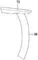
图33示出了带有面罩的头带的透视图,该面罩部分地附接到头带。Figure 33 shows a perspective view of a headgear with a visor partially attached to the headgear.
图34示出了带有面罩的头带的透视图,该面罩附接到头带。Figure 34 shows a perspective view of a headgear with a visor attached to the headgear.
图35示出了根据本发明的头带和面罩,该面罩处于工作位置。Figure 35 shows the headgear and mask according to the invention in the working position.
图36示出了根据本发明的头带和面罩,该面罩处于中间位置。Figure 36 shows a headgear and mask according to the invention in an intermediate position.
图37示出了根据本发明的头带和面罩,该面罩处于存放位置。Figure 37 shows a headgear and mask according to the present invention, the mask in a stowed position.
在附图的以下描述中,相同的附图标记表示相同或类似的部件。In the following description of the drawings, the same reference numerals denote the same or similar components.
具体实施方式Detailed ways
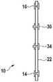
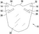
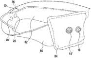
图1示出了根据本发明的面罩的前视图。面罩10(其具有透明材料的面板22作为主要部件)具有上边缘24和两个侧边缘26、28。边缘可以以多种方式成形。例如,可以避免任何拐角,或者可以选择其它多边形作为面罩的基本形状。上边缘24和侧边缘26、28相交的区域被称为面罩10的拐角区域30、32,但在此没有实际拐角的边缘之间的平滑过渡也是可能的。掀钮部件14、16设置在面罩10的拐角区域30、32中。两个止动部件34、36沿水平线布置在与上边缘24以及与侧边缘26、28相距一定距离处。它们相对于面罩的竖直对称轴线对称地布置在连接掀钮部件14、16的线的下方。Figure 1 shows a front view of a mask according to the invention. The
图2示出了根据本发明的面罩的上边缘的俯视图。在此,掀钮部件14、16被示出为凹掀钮部件。它们在上边缘附近穿透面板22。止动部件34、36是凸掀钮部件。它们布置在掀钮部件14、16下方,这在此处不可见,但结合图1可理解。Figure 2 shows a top view of the upper edge of a mask according to the invention. Here, the
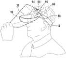
图3示出了根据本发明的面罩可以紧固到的帽子。帽子12可以是传统的帽子,如现今经常佩戴的那样。特别地,帽子12具有帽舌38。形成相对于面罩的掀钮部件而言的配对件的掀钮部件18、20布置在帽子12上。帽舌38用作面罩的止动部件的配对件。Figure 3 shows a hat to which a mask according to the invention may be fastened.
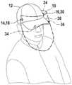
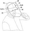
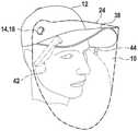
图4示出了帽子和面罩的组合,该面罩处于其工作位置。图5示出了帽子和面罩,该面罩处于中间位置。图6示出了根据本发明的帽子和面罩,该面罩处于存放位置。图7以侧视图示出了根据本发明的帽子和面罩,该面罩处于工作位置。在图4中,面罩处于其工作位置。它向下枢转,并保护佩戴者的面部。面罩10的进一步向下枢转是不可能的和/或不会意外地发生,因为止动部件34、36搁置在帽子12的帽舌38上。如图5中可见,通过使用掀钮部件14、18;16、20的相对可旋转性,可以以简单的方式将面罩10向上枢转出工作位置。在此,面罩10处于中间位置。在图6中,面罩已到达其存放位置。存放位置始终可以指定为面罩10保持稳定,即,不会落回佩戴者面部前方的位置。存放位置也可以比图6所示的更靠前或更靠后。图7再次以侧视图示出了工作位置,且特别是止动部件34、36在帽子12的帽舌38上的支承。面罩10相对于佩戴者面部的位置不仅可以通过使面罩10相对于帽子12枢转来实现。面罩10的不同位置也可以通过改变帽子12相对于佩戴者面部的位置来实现,即,通过例如以使帽舌38进一步向上指向的方式佩戴帽子来实现。Figure 4 shows the combination of hat and mask in its working position. Figure 5 shows the hat and visor in an intermediate position. Figure 6 shows a hat and mask according to the invention in a storage position. Figure 7 shows a hat and a mask according to the invention in a side view, the mask being in working position. In Fig. 4 the mask is in its working position. It pivots downward and protects the wearer's face. Further downward pivoting of the
图8示出了根据本发明的面罩的前视图。图9示出了根据本发明的面罩的上边缘的俯视图。在根据本发明的面罩的该实施例中,止动部件由止动条40形成。该止动条40优选地由泡沫构成。有用的是,泡沫条是自粘的并且从内侧胶合到面罩10的面板22。Figure 8 shows a front view of a mask according to the invention. Figure 9 shows a top view of the upper edge of a mask according to the invention. In this embodiment of the mask according to the invention, the stop means are formed by stop strips 40 . The retaining
图10以侧视图示出了根据本发明的帽子和面罩,该面罩位于其工作位置的正上方。当进一步向下降低面罩10时,止动条40放置在帽子12的帽舌38上,从而到达面罩10的工作位置。Figure 10 shows a hat and a mask according to the invention in a side view, the mask being located directly above its working position. When the
图11示出了根据本发明的面罩的前视图。对于该面罩10,设置有两个止动条40、41,使得面罩10具有两个工作位置。当降低面罩10时,止动条41首先放置在帽子的帽舌上。特别是在柔性止动条41的情况下,用一点力就可以使面罩进一步向下移动,使得止动条40然后搁置在帽子的帽舌上,从而呈现第二工作位置。Figure 11 shows a front view of a mask according to the invention. For this
图12示出了根据本发明的面罩的前视图。图13示出了根据本发明的面罩的上边缘的俯视图。在此,两个止动条42、44被紧固(优选地被胶合)到面罩10的面板22,其中,止动条42、44有用地在此也具有自粘侧。止动条42、44是楔形的。在每种情况下,楔形的较薄端是止动条42、44的下端。当面罩10降低时,它首先进入帽子的帽舌附近,使得面罩10最初可以容易地在帽子的帽舌上方枢转。随着进一步的枢转,楔形的较厚区域进入帽子的帽舌的附近,使得帽舌与帽子之间的力增加。以这种方式,面罩10的工作位置可以连续变化。Figure 12 shows a front view of a mask according to the invention. Figure 13 shows a top view of the upper edge of a mask according to the invention. Here, two stop strips 42 , 44 are fastened (preferably glued) to the
图14示出了根据本发明的帽子和面罩,该面罩处于存放位置。在此,可以看到楔形止动条的附接。在此,止动条仅部分地呈楔形。Figure 14 shows a hat and mask according to the invention in a storage position. Here, the attachment of the wedge-shaped stop strip can be seen. Here, the locking strip is only partially wedge-shaped.
图15示出了帽子和面罩的组合,该面罩处于工作位置。在此,面罩10位于其工作位置中的一个中,在这种情况下,楔形止动条42、44的已经很厚的区域连接到帽子12的帽舌38。即使面罩10进一步向上枢转,面罩10也将牢固地保持在工作位置,然后取走。Figure 15 shows the cap and mask combination, the mask in the working position. Here, the
图16示出了根据本发明的面罩的前视图。在此,织物部件52经由维可牢连接件(Velcro connections)46、48、50从内侧紧固到面罩10的面板22。织物部件52使面罩10向下延伸,从而提供增强的保护。此外,可以更换织物部件52。此外,织物部件52可以用于清洁面罩10。具有织物部件52的面罩10的本实施例结合使用楔形止动条42、44的面罩10的实施例被示出。然而,经由维可牢连接件46、48、50附接到面罩10的织物部件52也可以是对本文描述的面罩10的任何其它实施例的补充。织物部件也可以以另一种方式联接到面罩。它可以夹住、夹持、胶合或磁性连接到所述面罩。Figure 16 shows a front view of a mask according to the invention. Here, the
图17示出了根据本发明的面罩的前视图。两个通风槽54、56设置在面罩10的上边缘24附近。这使得用面罩10工作更令人满意,因为累积的温暖和潮湿的空气可以向上逸出。Figure 17 shows a front view of a mask according to the invention. Two
图18示出了根据本发明的面罩的前视图。图19示出了帽子和面罩的组合。隆起部58居中地布置在面罩10的上边缘24上。这提供了将面罩带入相对较低的工作位置的可能性,其中,面罩10在这样的位置仍然在居中区域中提供保护。然而,通风路径60、62可以设置到隆起部58的左侧和右侧,以允许潮湿和温暖的空气向上逸出。Figure 18 shows a front view of a mask according to the invention. Figure 19 shows a hat and mask combination. The raised
图20以侧视图示出了各种形状的止动条。止动条均以侧视图示出,即,使用它们的底侧,它们被紧固(优选地被胶合)到面罩的内侧。根据图20a的长方体止动条40优选地用于根据图9至图11和图17的实施例中。根据图20b、图20c和图20d的楔形和/或部分楔形的止动条42优选地与根据图12至图16以及图18和图19的实施例结合使用。Figure 20 shows various shapes of stop strips in side view. The stop strips are all shown in side view, ie using their bottom side, they are fastened (preferably glued) to the inside of the mask. The
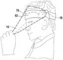
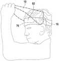
图21示出了帽子12和面罩10的组合,面罩10处于工作位置。图22示出了帽子12和面罩10的组合,面罩10处于中间位置。图23示出了帽子12和面罩10的组合,该面罩处于存放位置。面罩10和/或面罩10和帽子12的组合在许多方面类似于根据图12至图15的实施例。特别地,在面罩10上设置有楔形止动条,其中,仅左楔形止动条44在此可见。在右手侧,面罩10以相同或相似的方式配备。然而,在在此示出的面罩10上附加地设置有面罩侧上的紧固装置64。同样地,在帽子12上设置有头部侧上的紧固装置68。弹性带66(例如橡胶带)紧固到这种紧固装置64、68。橡胶带66在面罩10的外部和帽子12的外部延伸。紧固装置64、68优选地是面罩10和帽子12中的孔,其中,弹性带66从外部穿过孔64、68插入以用于从内部将其锁定。例如,可以简单地通过使弹性带66在其端部处打结来实现这种锁定。在根据图21的工作位置中,紧固装置具有最大或接近最大的间距,使得弹性带66被最大或几乎最大地张紧。弹性带66基本上平行于帽子12的边缘延伸。它稳定了面罩10的工作位置。如果面罩10向上枢转离开工作位置,即,经由根据图22的中间位置进入根据图23的存放位置,则弹性带有助于升高面罩10。弹性带66有助于将面罩10保持在其存放位置,其中,面罩10在此突出,即,通过面罩10的重量与带66的弹力之间的力平衡。在根据图21至图23的图示中,仅一个弹性带66是可见的。优选地,该设计相对于这些特征也是对称的,即,弹性带也固定在帽子12和面罩10的组合的右手侧上的对应紧固装置中。Figure 21 shows the combination of the
图24示出了根据本发明的面罩10的前视图。在此,止动条是不可见的,因为它们被贴附在面罩10外侧的贴附件78、80覆盖。除了从其它实施例中已知的特征之外,在此还可以看到面罩侧上的紧固装置64、65。在面罩的每一侧上,存在三个面罩侧上的紧固装置64、65,这些面罩侧上的紧固装置每个均像孔一样穿透面罩10。取决于机械条件,可以在每一侧上选择面罩侧上的紧固装置64、65中的特定一个,以用于紧固弹性带。面罩侧上的紧固装置64、65也可以组合。例如,弹性带可以从外到内被引导穿过面罩侧上的内部紧固装置64,并且可以穿过位于更外侧的面罩侧上的紧固装置或穿过位于更下方或更上方的面罩侧上的紧固装置64再次被引导出。以这种方式,可以改变弹性带的张紧力。Figure 24 shows a front view of a
图25示出了带有闩锁72的弹性带66的端部区域,闩锁72处于第一位置。图26示出了带有闩锁72的弹性带66的端部区域,闩锁72处于第二位置。闩锁72设置在在此示出的弹性带66的端部处。这使得不必通过打结来防止弹性带66离开面罩或帽子中的孔。在图25所示的闩锁72的位置,带66与闩锁72一起可以容易地被引导穿过孔。在闩锁72的横向位置,防止带66从孔中滑出。Figure 25 shows the end region of the
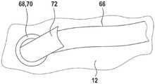
图27示出了带有闩锁72的弹性带66,同时带有闩锁72的弹性带66被引入帽子12中的孔中。在此可以看出,头部侧上的紧固装置68借助于空心铆钉70来实现。闩锁72基本上在弹性带66的延伸部中,使得弹性带66与闩锁72一起可以以简单的方式被引导穿过帽子12中的空心铆钉70。FIG. 27 shows the
图28示出了带有处于固定状态的闩锁66的弹性带。在此示出了闩锁72横向于弹性带66。因此,带66可以不再从帽子12中的孔中滑出。Figure 28 shows the elastic strap with the
图29示出了根据本发明的帽子12和面罩10,该面罩处于工作位置。图30示出了根据本发明的帽子12和面罩10,该面罩处于中间位置。图31示出了帽子12和面罩10的组合,该面罩处于存放位置。在根据本发明的面罩10的该实施例中,它配备有由泡沫制成的两个止动部件74,每个止动部件布置在掀钮部件14中的一个的位置处。在当前侧视图中,可以看到掀钮部件14和相关联的止动部件74,其中,面罩的另一侧上的设计是相同的或相似的。由泡沫制成的止动部件74从内侧胶合到面罩10上。止动部件74使得掀钮部件14的功能部分可以联接到帽子12上的配对件。止动部件74将面罩10稳定在所示位置中的每个位置,即,根据图29的工作位置、根据图30的中间位置和根据图31的存放位置。在这方面,止动部件74用作“制动器”,以防止面罩10相对于帽子12的意外枢转。Figure 29 shows the
图32示出了根据本发明的面罩的前视图。除了已经解释的根据本发明的面罩10的特征之外,在此还可以看到贴附件78、80,以覆盖由泡沫制成的止动部件,该止动部件施加到面罩10的另一侧。贴附件78、80基本上具有位于下方的泡沫止动部件的形状。它们基本上遵循面罩的轮廓,其中,上侧最初基本上笔直地延伸,然后形成向下的曲线。这种曲线继续直到到达贴附件78和/或由泡沫制成的止动部件的基本上笔直的内边缘为止。止动部件的上边缘和相邻的内边缘是笔直的。例如,它们可以基本上彼此垂直。优选地,将止动部件的上边缘和内边缘彼此连接的拐角是倒圆的。上边缘和内边缘的另一端经由弧形外边缘彼此连接。在另一实施例中,也可以规定,止动部件是圆形的。然后,其优选地在其中心被掀钮部件穿透。除了通常相对较软的泡沫之外,还可以使用较硬的塑料和/或由于其弹性而即使在长时间或频繁挤压后也始终恢复其基本形状的塑料。例如,可以使用PU泡沫、PVC泡沫、乳胶泡沫、硅酮泡沫、硬橡胶或这些材料的组合。Figure 32 shows a front view of a mask according to the invention. In addition to the already explained features of the
图33示出了带有面罩的头带的透视图,该面罩部分地附接到头带。头带82包括前部部件84和后部头部部件86。前部部件84被选择为比后部头部部件86更宽。前部部件84基本上是无弹性的,而后部头部部件86是弹性橡胶带。四个掀钮部件18、18'、20、20'附接到端带82的端部部件84,以使得当有人佩戴头带82时,它们横向布置在头部上,例如略高于耳朵以及在耳朵前方。带有止动部件76(其可见)的面罩10在左手侧安装在掀钮部件20、20'中的一个上(在此在掀钮部件20上)。在右手侧上,面罩10与头带82分离,使得两个掀钮部件18、18'都可见。通过在头带上布置两个或更多个掀钮部件,面罩10相对于头带82(并因此也相对于佩戴者头部)的位置可以改变。Figure 33 shows a perspective view of a headgear with a visor partially attached to the headgear. The
图34示出了带有面罩的头带的透视图,该面罩附接到头带。在此,可以看到面罩10紧固到前方的现在被覆盖的掀钮部件20(参见图33),而后掀钮部件20'未使用。Figure 34 shows a perspective view of a headgear with a visor attached to the headgear. Here, the
图35示出了根据本发明的头带和面罩,该面罩处于工作位置。图36示出了根据本发明的头带和面罩,该面罩处于中间位置。图37示出了根据本发明的头带和面罩,该面罩处于存放位置。在图35中,面罩10处于其工作位置。在左手侧掀钮部件16的区域中可以看到止动部件76。止动部件76(其优选地是泡沫部件)在头带82上摩擦,从而使制动效果可用。在没有佩戴者干预的情况下,面罩不会被调整或仅在极少数情况下被意外地调整。在图36中,面罩10略微升高。它也可以保持在该位置,因为用作制动器的止动部件76始终施加制动效果。在图37中,已经到达了可用的存放位置,并且面罩基本上水平地面向前。止动部件76也借助于头带82上的摩擦将面罩10制动在该位置。Figure 35 shows the headgear and mask according to the invention in the working position. Figure 36 shows a headgear and mask according to the invention in an intermediate position. Figure 37 shows a headgear and mask according to the present invention, the mask in a stowed position. In Fig. 35, the
在本发明的图示实施例中,示出了不同类型的帽子,即,具有封闭头部部分的帽子和具有敞开头部部分的帽子。各种面罩可以与所示的帽子变体中的任一个组合。而且,与头带相关联示出的所有特征都可以与帽子相关联来实现。这同样适用于以相反方式与帽子相关联示出的所有特征,除非帽子具有帽舌是至关重要的。除了帽子和头带之外,使用夹子(例如通常用于发型的夹子)也在本发明的范围内。佩戴夹子,使其在前部封闭且在后部敞开。面罩可以以与头带相同的方式附接到夹子。In the illustrated embodiment of the invention, different types of hats are shown, namely hats with a closed head portion and hats with an open head portion. Various visors can be combined with any of the hat variants shown. Moreover, all features shown in relation to the headband can also be implemented in relation to the hat. The same applies to all features shown in relation to the hat in reverse, unless it is essential that the hat has a visor. In addition to hats and headbands, it is also within the scope of the present invention to use clips such as are commonly used for hairstyles. Wear the clip so it is closed at the front and open at the back. The mask can be attached to the clip in the same way as the headband.
在前面的描述中、在附图中以及在权利要求中公开的本发明的特征对于单独地和以任何组合方式实施本发明都是必不可少的。The features of the invention disclosed in the foregoing description, in the drawings and in the claims are essential for implementing the invention both individually and in any combination.
附图标记列表:List of reference signs:
10 面罩10 masks
12 帽子12 hats
14 掀钮部件14 flip button parts
16 掀钮部件16 flip button parts
18 掀钮部件18 flip button parts
18' 掀钮部件18' flip button assembly
20 掀钮部件20 flip button parts
20' 掀钮部件20' flip button assembly
22 面板22 panels
24 上边缘24 upper edge
26 侧边缘26 side edge
28 侧边缘28 side edge
30 拐角区域30 corner area
32 拐角区域32 corner area
34 止动部件/凸掀钮部件34 Stop part / raised button part
36 止动部件/凸掀钮部件36 Stop part / raised button part
38 帽舌38 visor
40 止动部件/止动条/泡沫条40 Stop parts/stop strips/foam strips
41 止动部件/止动条/泡沫条41 Stop parts/stop strips/foam strips
42 止动部件/止动条/楔形泡沫部件42 Stop part/stop bar/wedge foam part
44 止动部件/止动条/楔形泡沫部件44 Stop part/stop bar/wedge foam part
46 维可牢连接件46 Velcro connectors
48 维可牢连接件48 Velcro connectors
50 维可牢连接件50 Velcro connectors
52 织物部件52 fabric parts
54 通风槽54 ventilation slot
56 通风槽56 ventilation slot
58 隆起部58 Bulge
60 通风路径60 ventilation paths
62 通风路径62 ventilation path
64 面罩侧上的带紧固装置64 Strap fastening on mask side
65 面罩侧上的带紧固装置65 Strap fastening on mask side
66 弹性带66 elastic band
68 头部侧上的带紧固装置68 Belt fastening on head side
69 头部侧上的带紧固装置69 Strap fastening on head side
70 空心铆钉70 hollow rivets
72 闩锁72 latches
74 止动部件74 stop parts
76 止动部件76 Stop parts
78 贴附件78 stickers
80 贴附件80 attachments
82 头带82 headband
84 前部部件84 front part
86 后部头部部件。86 Rear head piece.
Claims (28)
Translated fromChineseApplications Claiming Priority (7)
| Application Number | Priority Date | Filing Date | Title |
|---|---|---|---|
| DE102020109715 | 2020-04-07 | ||
| DE102020109715.8 | 2020-04-07 | ||
| DE102020111000 | 2020-04-22 | ||
| DE102020111000.6 | 2020-04-22 | ||
| DE102020111445.1 | 2020-04-27 | ||
| DE102020111445.1ADE102020111445B3 (en) | 2020-04-07 | 2020-04-27 | Visor for attachment to a cap or a headband or a clasp |
| PCT/EP2021/056867WO2021204508A1 (en) | 2020-04-07 | 2021-03-17 | Visor for fastening to a cap or a headband or a brace |
Publications (1)
| Publication Number | Publication Date |
|---|---|
| CN115361884Atrue CN115361884A (en) | 2022-11-18 |
Family
ID=76853920
Family Applications (1)
| Application Number | Title | Priority Date | Filing Date |
|---|---|---|---|
| CN202180026505.3APendingCN115361884A (en) | 2020-04-07 | 2021-03-17 | Masks for fastening to hats or headbands or clips |
Country Status (6)
| Country | Link |
|---|---|
| US (1) | US20230121536A1 (en) |
| EP (1) | EP4132308B1 (en) |
| CN (1) | CN115361884A (en) |
| DE (2) | DE102020008054A1 (en) |
| ES (1) | ES2985411T3 (en) |
| WO (1) | WO2021204508A1 (en) |
Citations (11)
| Publication number | Priority date | Publication date | Assignee | Title |
|---|---|---|---|---|
| US2262449A (en)* | 1939-10-23 | 1941-11-11 | Buegeleisen Joseph | Head windshield |
| US2729820A (en)* | 1953-01-19 | 1956-01-10 | Sellstrom Mfg Co | Safety headgear |
| US2731637A (en)* | 1954-04-14 | 1956-01-24 | Kaplan Harry Leland | Sunshade |
| US2915756A (en)* | 1958-10-23 | 1959-12-08 | Pulmasan Safety Equipment Corp | Face shield |
| US3577565A (en)* | 1968-08-26 | 1971-05-04 | Ilc Ind Inc | Face shield |
| US3594816A (en)* | 1969-12-18 | 1971-07-27 | American Safety Equip | Safety helmet face shield |
| US3727235A (en)* | 1972-01-13 | 1973-04-17 | Ilc Ind Inc | Retractable face protective assembly |
| US4117553A (en)* | 1977-04-12 | 1978-10-03 | Bay William P | Helmet shield and visor apparatus |
| US4536892A (en)* | 1984-04-23 | 1985-08-27 | Mine Safety Appliances Company | Riot faceshield assembly |
| US4986282A (en)* | 1987-09-09 | 1991-01-22 | Stackhouse Wyman H | Face shield system |
| US5765223A (en)* | 1996-06-04 | 1998-06-16 | Mccausland; Mary L. | Face shield |
Family Cites Families (88)
| Publication number | Priority date | Publication date | Assignee | Title |
|---|---|---|---|---|
| US1202513A (en)* | 1915-06-08 | 1916-10-24 | Arlington Company | Face-shield. |
| US2277090A (en)* | 1939-05-03 | 1942-03-24 | Feiler Malwin | Face protector |
| GB533802A (en) | 1939-11-27 | 1941-02-20 | Fairey Aviat Co Ltd | Improvements in or relating to protective visors |
| US2755476A (en)* | 1954-04-02 | 1956-07-24 | Fibre Metal Products Company | Spark deflector/visor assembly |
| US2798222A (en)* | 1954-07-13 | 1957-07-09 | Mine Safety Appliances Co | Protective device |
| DE1953799U (en) | 1966-11-25 | 1967-01-19 | Rudolf Voelkel | NORMAL WORK VISOR CAP WITH FACE AND EYE PROTECTION. |
| US3491372A (en)* | 1967-11-13 | 1970-01-27 | Gentex Corp | Head gear with retractable eye shield |
| US3685054A (en)* | 1968-10-07 | 1972-08-22 | Bullard Co | Apparatus for mounting a face shield onto a rigid hat |
| US3686690A (en)* | 1968-11-19 | 1972-08-29 | American Safety Equip | Face shield |
| US3613115A (en)* | 1969-08-20 | 1971-10-19 | Ilc Ind Inc | Detachable face shield support for a helmet |
| US3605115A (en)* | 1969-09-10 | 1971-09-20 | Esb Inc | Shield |
| US3774239A (en)* | 1971-03-22 | 1973-11-27 | Ilc Ind Inc | Visor assembly having replaceable face shield |
| US3797042A (en)* | 1972-07-14 | 1974-03-19 | L Gager | Visor and face shield helmet attachment |
| US3868727A (en)* | 1973-09-24 | 1975-03-04 | James W Paschall | Welding hood |
| USD254638S (en)* | 1977-04-07 | 1980-04-08 | Bay Jr William P | Combined helmet shield and visor |
| US4333180A (en)* | 1980-12-11 | 1982-06-08 | Bay William P | Helmet visor |
| DE3409786A1 (en)* | 1984-03-16 | 1985-10-10 | Artur 7060 Schorndorf Föhl | SAFETY HELMET, IN PARTICULAR HELMET |
| US4726074A (en)* | 1985-03-15 | 1988-02-23 | Paul Baclit | Detachable visor |
| US4625341A (en)* | 1985-07-18 | 1986-12-02 | Bell Helmets Inc. | Removably attachable shield for helmet visor |
| US4701965A (en)* | 1985-10-11 | 1987-10-27 | Landis Timothy J | Visor-type mask for dentists |
| US4653123A (en)* | 1986-03-07 | 1987-03-31 | Bell Helmets Inc. | Aerodynamic bicyclist's helmet construction |
| DE3635019A1 (en) | 1986-10-15 | 1988-04-21 | Gottfried Biener | Face guard |
| US4766609A (en)* | 1987-03-31 | 1988-08-30 | Firequip Helmets, Inc. | Fire fighter helmet and face shield |
| US4821341A (en)* | 1987-05-13 | 1989-04-18 | Baptiste Trevor I | Sun-visor and headpiece combination and package therefor |
| USD306363S (en)* | 1987-09-09 | 1990-02-27 | Stackhouse Wyman H | Face shield |
| US4950445A (en)* | 1988-02-05 | 1990-08-21 | Cabot Safety Corporation | Method of vacuum forming disposable faceshield |
| US4864653A (en)* | 1988-05-16 | 1989-09-12 | Landis Timothy J | Protective shield and visor supporting same |
| US4928324A (en)* | 1988-10-18 | 1990-05-29 | Jerry Evans | Hard hat face shield bracket |
| USD318147S (en)* | 1988-12-20 | 1991-07-09 | Bfd, Inc. | Face shield |
| US5067174A (en)* | 1989-05-24 | 1991-11-26 | Ritchey Albert E | Protective headgear |
| US5303423A (en)* | 1990-01-12 | 1994-04-19 | Splash Shield, Limited Partnership | Face shield/mask combination |
| US5107543A (en)* | 1990-07-25 | 1992-04-28 | Hansen Gary M | Goggle engaging face mask device and method |
| USD349362S (en)* | 1992-08-24 | 1994-08-02 | Russell John P | Face shield |
| US5365615A (en)* | 1993-01-12 | 1994-11-22 | Piszkin Thomas M | Headgear faceshield w/non-invasive universal-mounting |
| USD362086S (en)* | 1993-07-21 | 1995-09-05 | Infection Control Products, Inc. | Face protector having pivoting shield |
| USD361160S (en)* | 1993-09-07 | 1995-08-08 | Infection Control Products, Inc. | Face protector with pivoting face shield and stop |
| US5473778A (en)* | 1993-12-29 | 1995-12-12 | John E. Pollock | Sunglass cap |
| US5440760A (en)* | 1994-02-04 | 1995-08-15 | Tecnol Medical Products, Inc. | Disposable face shield |
| US5561863A (en)* | 1994-10-04 | 1996-10-08 | Kimberly-Clark Corporation | Surgical face mask |
| US5544361A (en)* | 1995-01-19 | 1996-08-13 | Gary A. Davidson | Headgear mountable protective face shield |
| US5555570A (en)* | 1995-03-31 | 1996-09-17 | Bay, Jr.; William P. | Bicycle helmet face shield apparatus and method |
| US5673431A (en)* | 1995-08-25 | 1997-10-07 | Dwight A. Marshall | Face mask safety shield |
| US5732410A (en)* | 1996-10-24 | 1998-03-31 | Machson; Roger | Face shield having closeable drape |
| USD404849S (en)* | 1997-07-24 | 1999-01-26 | Cabot Safety Intermediate Corporation | Disposable face shield |
| AU138350S (en)* | 1997-11-13 | 1999-09-14 | Welder's face shield | |
| US6173447B1 (en)* | 1997-11-13 | 2001-01-16 | Gary L. Arnold | Demountable protective eye shield assembly for cap visor |
| US5924129A (en)* | 1998-04-09 | 1999-07-20 | Gill; Jeannie | Sunguard for use with headgear |
| US5991930A (en)* | 1998-05-07 | 1999-11-30 | Sorrentino; James J. | Protective helmet with attachable visor |
| US6216695B1 (en)* | 1998-05-07 | 2001-04-17 | Softy-Flex Inc. | Disposable surgical face mask with retractable eye shield |
| US6378133B1 (en)* | 1998-11-17 | 2002-04-30 | S.L.T. Japan Co., Ltd. | Visor for intercepting laser light for medical treatment |
| US5970514A (en)* | 1999-02-05 | 1999-10-26 | Wang-Lee; Min-Young | Face mask |
| US6375865B1 (en)* | 1999-08-11 | 2002-04-23 | Paulson Manufacturing Corporation | Electric-arc resistant composition |
| US6237162B1 (en)* | 2000-02-18 | 2001-05-29 | Ronald Gill | Helmet cover with positive attachment |
| US6622309B1 (en)* | 2001-04-10 | 2003-09-23 | Joseph Edmonds | Athletic face shield |
| US6381750B1 (en)* | 2001-09-25 | 2002-05-07 | Norman B. Mangan | Headgear mountable shield and method of use |
| CA2524570A1 (en)* | 2003-05-02 | 2004-11-18 | Op-D-Op, Inc. | Lightweight ventilated face shield frame |
| US7540039B2 (en)* | 2003-06-19 | 2009-06-02 | Reaux Brian K | Face and eye covering device |
| US6996852B1 (en)* | 2003-08-18 | 2006-02-14 | Cabrera Juan C | Head covering |
| EP1819250A1 (en)* | 2004-12-08 | 2007-08-22 | Paul-Eric Preising | Protective device |
| DE102005027151A1 (en) | 2004-12-08 | 2006-06-29 | Paul-Eric Preising | Protection device for person, has transparent protective screen and rubber strip that temporarily endure against thermal effect emanated by accidental arcing, where screen is placed before person face and strip covering neck and chest area |
| USD526446S1 (en)* | 2004-12-19 | 2006-08-08 | Michael Leslie Cowan | Face shield for use with headgear |
| US6996846B1 (en)* | 2005-06-02 | 2006-02-14 | Armen Karapetyan | Visor-type face shield for dentist |
| USD541991S1 (en)* | 2006-05-12 | 2007-05-01 | Raymond Lawrence | Safety helmet visor |
| US7716754B1 (en)* | 2007-03-27 | 2010-05-18 | William Ross | Ski helmet with adjustable face shield |
| US8291512B2 (en)* | 2010-04-28 | 2012-10-23 | Walter Stoll | Face shield |
| US8336123B2 (en)* | 2011-05-20 | 2012-12-25 | Honeywell International, Inc. | Latching mechanism for retention of face shield lens |
| US20150351468A9 (en)* | 2013-03-01 | 2015-12-10 | Bruce Chinquee | Face Mask |
| US20140259253A1 (en)* | 2013-03-15 | 2014-09-18 | Leisher Michael Jacob | Apparatuses, systems and methods for providing protection against hazards |
| WO2014174284A1 (en)* | 2013-04-23 | 2014-10-30 | Surgivisor Limited | Personal protective system |
| JP5894199B2 (en)* | 2014-01-31 | 2016-03-23 | スリーエム イノベイティブ プロパティズ カンパニー | Shield to protect eyes |
| US20160360820A1 (en)* | 2015-06-12 | 2016-12-15 | Illinois Tool Works Inc. | Hard Hat Adapter for a Welding Face Member |
| USD781508S1 (en)* | 2016-03-04 | 2017-03-14 | Otos Wing Co., Ltd. | Sight glass of welding mask |
| KR101882310B1 (en)* | 2016-04-22 | 2018-07-27 | 주식회사 오토스윙 | Face Protector |
| US20180042324A1 (en)* | 2016-08-10 | 2018-02-15 | Bradley W. King | Cap with integrated and interchangeable eye protection |
| US20200281770A1 (en)* | 2019-03-04 | 2020-09-10 | Manuel Salvador Moreno | Combination sleep eye mask and face mask |
| DE202020101562U1 (en)* | 2020-03-23 | 2020-04-01 | POS TUNING Udo Voßhenrich GmbH & Co. KG | Face protection |
| USD908973S1 (en)* | 2020-04-07 | 2021-01-26 | Denso International America, Inc. | Medical face shield |
| USD907300S1 (en)* | 2020-04-07 | 2021-01-05 | II Daniel Patrick Brown | Brim mounted face shield |
| US11147323B1 (en)* | 2020-04-17 | 2021-10-19 | Racing Optics, Inc. | Protective face shield attachable to headwear |
| US11399581B2 (en)* | 2020-04-17 | 2022-08-02 | Racing Optics, Inc. | Protective face shield attachable to headwear |
| US20210331004A1 (en)* | 2020-04-27 | 2021-10-28 | LevMarc LLC | Protective equipment |
| US20210337902A1 (en)* | 2020-04-30 | 2021-11-04 | Lifethereal LLC | Face shield and method of making the same |
| US20210368886A1 (en)* | 2020-05-29 | 2021-12-02 | Mark Andrew Swart | Wearable Microbe Protective Shield |
| US11425953B2 (en)* | 2020-06-11 | 2022-08-30 | Extang Corporation | Face shield for baseball cap |
| USD959754S1 (en)* | 2020-08-20 | 2022-08-02 | Lorenzo Hughes | Face mask |
| USD963951S1 (en)* | 2020-10-09 | 2022-09-13 | Robert Franklin | Cap shield |
| US20220117328A1 (en)* | 2020-10-21 | 2022-04-21 | KodifyMe FreeSpacers, Inc. | Adjustable face shield |
| USD969412S1 (en)* | 2021-02-02 | 2022-11-08 | Joshua Don Painter | Padded face shield |
- 2020
- 2020-04-27DEDE102020008054.5Apatent/DE102020008054A1/enactivePending
- 2020-04-27DEDE102020111445.1Apatent/DE102020111445B3/enactiveActive
- 2021
- 2021-03-17USUS17/917,866patent/US20230121536A1/ennot_activeAbandoned
- 2021-03-17CNCN202180026505.3Apatent/CN115361884A/enactivePending
- 2021-03-17WOPCT/EP2021/056867patent/WO2021204508A1/ennot_activeCeased
- 2021-03-17EPEP21713377.6Apatent/EP4132308B1/enactiveActive
- 2021-03-17ESES21713377Tpatent/ES2985411T3/enactiveActive
Patent Citations (11)
| Publication number | Priority date | Publication date | Assignee | Title |
|---|---|---|---|---|
| US2262449A (en)* | 1939-10-23 | 1941-11-11 | Buegeleisen Joseph | Head windshield |
| US2729820A (en)* | 1953-01-19 | 1956-01-10 | Sellstrom Mfg Co | Safety headgear |
| US2731637A (en)* | 1954-04-14 | 1956-01-24 | Kaplan Harry Leland | Sunshade |
| US2915756A (en)* | 1958-10-23 | 1959-12-08 | Pulmasan Safety Equipment Corp | Face shield |
| US3577565A (en)* | 1968-08-26 | 1971-05-04 | Ilc Ind Inc | Face shield |
| US3594816A (en)* | 1969-12-18 | 1971-07-27 | American Safety Equip | Safety helmet face shield |
| US3727235A (en)* | 1972-01-13 | 1973-04-17 | Ilc Ind Inc | Retractable face protective assembly |
| US4117553A (en)* | 1977-04-12 | 1978-10-03 | Bay William P | Helmet shield and visor apparatus |
| US4536892A (en)* | 1984-04-23 | 1985-08-27 | Mine Safety Appliances Company | Riot faceshield assembly |
| US4986282A (en)* | 1987-09-09 | 1991-01-22 | Stackhouse Wyman H | Face shield system |
| US5765223A (en)* | 1996-06-04 | 1998-06-16 | Mccausland; Mary L. | Face shield |
Also Published As
| Publication number | Publication date |
|---|---|
| EP4132308B1 (en) | 2024-05-01 |
| WO2021204508A1 (en) | 2021-10-14 |
| DE102020111445B3 (en) | 2021-08-05 |
| ES2985411T3 (en) | 2024-11-05 |
| US20230121536A1 (en) | 2023-04-20 |
| EP4132308A1 (en) | 2023-02-15 |
| DE102020008054A1 (en) | 2021-10-07 |
Similar Documents
| Publication | Publication Date | Title |
|---|---|---|
| JP4592871B2 (en) | helmet | |
| US6952841B2 (en) | Sports goggles | |
| EP1183955B1 (en) | Helmet chin covering device and helmet using the same | |
| US6691314B1 (en) | Face mask, head harness, and protective hood for firefighter | |
| JP3955127B2 (en) | helmet | |
| US20120210482A1 (en) | Face guard frame, system and method | |
| US11957198B2 (en) | Convertible hat | |
| JP4285661B2 (en) | Face mask | |
| US6931664B1 (en) | Facemask harness | |
| ITUB20154758A1 (en) | BAND POGGIA FRONT FOR HELMETS AND HELMET PROVIDED WITH SUCH FRONT POGGIA BAND. | |
| US2790175A (en) | Face guard | |
| US20230037426A1 (en) | Mouth cover | |
| CN115361884A (en) | Masks for fastening to hats or headbands or clips | |
| US20220039494A1 (en) | Facial covering system | |
| JP3228164U (en) | mask | |
| KR100678716B1 (en) | Mask with filter | |
| KR200491983Y1 (en) | A wasp defensing cloths | |
| US20070000024A1 (en) | Kerchief | |
| JP4672051B2 (en) | Leg guard for ball game | |
| JP2002177435A (en) | Baseball or softball protector | |
| JP2826705B2 (en) | Winter ski mask | |
| JP2001336020A (en) | Helmet with inner cap | |
| US6820286B2 (en) | Protective mask | |
| EP2989916A1 (en) | Clothing accessory that protects from the cold | |
| CN211021119U (en) | Multi-purpose zipper baseball cap |
Legal Events
| Date | Code | Title | Description |
|---|---|---|---|
| PB01 | Publication | ||
| PB01 | Publication | ||
| SE01 | Entry into force of request for substantive examination | ||
| SE01 | Entry into force of request for substantive examination |