CN115349944A - Pulse Ablation System - Google Patents
Pulse Ablation SystemDownload PDFInfo
- Publication number
- CN115349944A CN115349944ACN202211085639.5ACN202211085639ACN115349944ACN 115349944 ACN115349944 ACN 115349944ACN 202211085639 ACN202211085639 ACN 202211085639ACN 115349944 ACN115349944 ACN 115349944A
- Authority
- CN
- China
- Prior art keywords
- electrode
- pulse
- pulse ablation
- impedance
- ablation
- Prior art date
- Legal status (The legal status is an assumption and is not a legal conclusion. Google has not performed a legal analysis and makes no representation as to the accuracy of the status listed.)
- Pending
Links
Images


Classifications
- A—HUMAN NECESSITIES
- A61—MEDICAL OR VETERINARY SCIENCE; HYGIENE
- A61B—DIAGNOSIS; SURGERY; IDENTIFICATION
- A61B18/00—Surgical instruments, devices or methods for transferring non-mechanical forms of energy to or from the body
- A61B18/04—Surgical instruments, devices or methods for transferring non-mechanical forms of energy to or from the body by heating
- A61B18/12—Surgical instruments, devices or methods for transferring non-mechanical forms of energy to or from the body by heating by passing a current through the tissue to be heated, e.g. high-frequency current
- A61B18/14—Probes or electrodes therefor
- A61B18/1492—Probes or electrodes therefor having a flexible, catheter-like structure, e.g. for heart ablation
- A—HUMAN NECESSITIES
- A61—MEDICAL OR VETERINARY SCIENCE; HYGIENE
- A61B—DIAGNOSIS; SURGERY; IDENTIFICATION
- A61B18/00—Surgical instruments, devices or methods for transferring non-mechanical forms of energy to or from the body
- A61B2018/00315—Surgical instruments, devices or methods for transferring non-mechanical forms of energy to or from the body for treatment of particular body parts
- A61B2018/00345—Vascular system
- A61B2018/00351—Heart
- A—HUMAN NECESSITIES
- A61—MEDICAL OR VETERINARY SCIENCE; HYGIENE
- A61B—DIAGNOSIS; SURGERY; IDENTIFICATION
- A61B18/00—Surgical instruments, devices or methods for transferring non-mechanical forms of energy to or from the body
- A61B2018/00571—Surgical instruments, devices or methods for transferring non-mechanical forms of energy to or from the body for achieving a particular surgical effect
- A61B2018/00613—Irreversible electroporation
- A—HUMAN NECESSITIES
- A61—MEDICAL OR VETERINARY SCIENCE; HYGIENE
- A61B—DIAGNOSIS; SURGERY; IDENTIFICATION
- A61B18/00—Surgical instruments, devices or methods for transferring non-mechanical forms of energy to or from the body
- A61B2018/00636—Sensing and controlling the application of energy
- A61B2018/00696—Controlled or regulated parameters
- A61B2018/00732—Frequency
- A—HUMAN NECESSITIES
- A61—MEDICAL OR VETERINARY SCIENCE; HYGIENE
- A61B—DIAGNOSIS; SURGERY; IDENTIFICATION
- A61B18/00—Surgical instruments, devices or methods for transferring non-mechanical forms of energy to or from the body
- A61B2018/00636—Sensing and controlling the application of energy
- A61B2018/00696—Controlled or regulated parameters
- A61B2018/00738—Depth, e.g. depth of ablation
- A—HUMAN NECESSITIES
- A61—MEDICAL OR VETERINARY SCIENCE; HYGIENE
- A61B—DIAGNOSIS; SURGERY; IDENTIFICATION
- A61B18/00—Surgical instruments, devices or methods for transferring non-mechanical forms of energy to or from the body
- A61B2018/00636—Sensing and controlling the application of energy
- A61B2018/00696—Controlled or regulated parameters
- A61B2018/00767—Voltage
- A—HUMAN NECESSITIES
- A61—MEDICAL OR VETERINARY SCIENCE; HYGIENE
- A61B—DIAGNOSIS; SURGERY; IDENTIFICATION
- A61B18/00—Surgical instruments, devices or methods for transferring non-mechanical forms of energy to or from the body
- A61B2018/00636—Sensing and controlling the application of energy
- A61B2018/00773—Sensed parameters
- A61B2018/00839—Bioelectrical parameters, e.g. ECG, EEG
- A—HUMAN NECESSITIES
- A61—MEDICAL OR VETERINARY SCIENCE; HYGIENE
- A61B—DIAGNOSIS; SURGERY; IDENTIFICATION
- A61B18/00—Surgical instruments, devices or methods for transferring non-mechanical forms of energy to or from the body
- A61B2018/00636—Sensing and controlling the application of energy
- A61B2018/00773—Sensed parameters
- A61B2018/00875—Resistance or impedance
- A—HUMAN NECESSITIES
- A61—MEDICAL OR VETERINARY SCIENCE; HYGIENE
- A61B—DIAGNOSIS; SURGERY; IDENTIFICATION
- A61B18/00—Surgical instruments, devices or methods for transferring non-mechanical forms of energy to or from the body
- A61B2018/00636—Sensing and controlling the application of energy
- A61B2018/00904—Automatic detection of target tissue
Landscapes
- Health & Medical Sciences (AREA)
- Surgery (AREA)
- Engineering & Computer Science (AREA)
- Life Sciences & Earth Sciences (AREA)
- Biomedical Technology (AREA)
- Molecular Biology (AREA)
- Nuclear Medicine, Radiotherapy & Molecular Imaging (AREA)
- Plasma & Fusion (AREA)
- Physics & Mathematics (AREA)
- Heart & Thoracic Surgery (AREA)
- Medical Informatics (AREA)
- Otolaryngology (AREA)
- Animal Behavior & Ethology (AREA)
- General Health & Medical Sciences (AREA)
- Public Health (AREA)
- Veterinary Medicine (AREA)
- Cardiology (AREA)
- Measurement And Recording Of Electrical Phenomena And Electrical Characteristics Of The Living Body (AREA)
Abstract
Description
Translated fromChinese技术领域technical field
本发明涉及脉冲消融技术领域,特别涉及一种脉冲消融系统。The invention relates to the technical field of pulse ablation, in particular to a pulse ablation system.
背景技术Background technique
心律失常会造成各种危险情况,包括失去同步房室收缩和血流停滞,从而导致各种疾病甚至死亡。房性心律失常的主要原因是心脏左心房或右心房内的杂散电信号。Arrhythmias can cause a variety of dangerous conditions, including desynchronized atrioventricular contraction and stagnation of blood flow, which can lead to various diseases and even death. The main cause of atrial arrhythmias is stray electrical signals in the left or right atrium of the heart.
采用脉冲消融系统实施的消融疗法可用于治疗房性心律失常。通过脉冲消融系统中的脉冲导管将电极送达至目标组织处,通过电极瞬间放电在目标组织的细胞膜上形成不可逆的微孔,以使目标组织形成不可逆损伤。据此,实现非热消融,避免产生导致心律失常的杂散电信号。由于不同组织细胞对电压阈值不同,采用脉冲消融可选择性消融目标组织细胞,而不对非目标组织细胞产生影响。Ablation therapy delivered with a pulsed ablation system can be used to treat atrial arrhythmias. The electrode is delivered to the target tissue through the pulse catheter in the pulse ablation system, and irreversible micropores are formed on the cell membrane of the target tissue through the instantaneous discharge of the electrode, so that the target tissue is irreversibly damaged. Accordingly, non-thermal ablation is realized, and stray electrical signals that cause arrhythmia are avoided. Since different tissue cells have different voltage thresholds, pulse ablation can selectively ablate target tissue cells without affecting non-target tissue cells.
脉冲消融导管中电极与目标组织的贴靠程度直接影响脉冲消融效果,因此脉冲消融系统在使用时有必要确认脉冲消融导管的电极是否与目标组织贴靠到位。The adhering degree of the electrode in the pulse ablation catheter to the target tissue directly affects the effect of pulse ablation, so it is necessary to confirm whether the electrode of the pulse ablation catheter is in place with the target tissue when using the pulse ablation system.
发明内容Contents of the invention
本发明要解决的技术问题是为了克服现有技术中脉冲消融导管使用时不便判断电极和目标组织是否贴靠到位的缺陷,提供了一种脉冲消融系统。The technical problem to be solved by the present invention is to provide a pulse ablation system in order to overcome the defect that it is inconvenient to judge whether the electrode and the target tissue are in place when the pulse ablation catheter is used in the prior art.
本发明是通过下述技术方案来解决上述技术问题:The present invention solves the above technical problems through the following technical solutions:
本发明实施例提供了一种脉冲消融系统,所述脉冲消融系统包括:所述脉冲消融系统包括:脉冲消融导管和脉冲能量输出设备;An embodiment of the present invention provides a pulse ablation system, the pulse ablation system includes: the pulse ablation system includes: a pulse ablation catheter and a pulse energy output device;
所述脉冲消融导管包括远端管体,和设置在所述远端管体上的电极,所述电极用于在目标组织形成病灶;The pulse ablation catheter includes a distal tube body, and electrodes arranged on the distal tube body, and the electrodes are used to form a lesion in the target tissue;
所述脉冲能量输出设备与所述电极电性连接,用于为所述电极提供脉冲消融信号,所述脉冲能量输出设备还包括:The pulse energy output device is electrically connected to the electrode, and is used to provide a pulse ablation signal for the electrode, and the pulse energy output device further includes:
阻抗检测模块,与所述电极电性连接,用于向所述电极输出测试信号以获取被消融目标的基础阻抗和所述电极当前所处环境的接触阻抗;An impedance detection module, electrically connected to the electrodes, for outputting test signals to the electrodes to obtain the basic impedance of the ablated target and the contact impedance of the current environment where the electrodes are located;
贴靠程度确定模块,与所述阻抗检测模块电性连接,用于根据所述基础阻抗和所述接触阻抗确定所述电极与所述目标组织的贴靠程度。The adhering degree determining module is electrically connected with the impedance detecting module, and is used for determining the adhering degree of the electrode and the target tissue according to the basic impedance and the contact impedance.
在一个实施例中,在所述远端管体上设置有多个电极,两个所述电极形成一组电极对;所述阻抗检测模块包括:In one embodiment, a plurality of electrodes are provided on the distal tube body, and two electrodes form a group of electrode pairs; the impedance detection module includes:
第一输出单元,用于向所述电极对输出所述测试信号;a first output unit, configured to output the test signal to the electrode pair;
第一确定单元,用于获取所述电极对基于所述测试信号产生的电压,并根据所述测试信号和所述电压确定所述基础阻抗或所述接触阻抗。The first determination unit is configured to obtain the voltage generated by the electrode pair based on the test signal, and determine the basic impedance or the contact impedance according to the test signal and the voltage.
在一个实施例中,所述贴靠程度确定模块包括:In one embodiment, the abutment degree determination module includes:
第二确定单元,用于确定所述接触阻抗和所述基础阻抗的差值;a second determining unit, configured to determine a difference between the contact impedance and the basic impedance;
第三确定单元,用于根据所述差值和预设阈值,确定所述电极与目标组织的贴靠程度。The third determination unit is configured to determine the degree of adhering the electrode to the target tissue according to the difference and a preset threshold.
在一个实施例中,当所述电极参与至少两组所述电极对接收所述测试信号时,In one embodiment, when the electrodes participate in at least two groups of the electrode pairs receiving the test signal,
所述第二确定单元具体用于获取所述电极所参与的每一组所述电极对的基础阻抗和接触阻抗的差值;The second determining unit is specifically configured to obtain the difference between the basic impedance and the contact impedance of each group of the electrode pairs in which the electrode participates;
所述第三确定单元具体用于根据所述差值中的最大值和所述预设阈值确定所述电极与目标组织的贴靠程度。The third determination unit is specifically configured to determine the degree of affixation of the electrode to the target tissue according to the maximum value of the difference and the preset threshold.
在一个实施例中,所述脉冲消融系统还包括控制模块,In one embodiment, the pulse ablation system further includes a control module,
所述控制模块与所述阻抗检测模块电性连接,用于根据所述接触阻抗确定脉冲消融信号;The control module is electrically connected to the impedance detection module, and is used to determine a pulse ablation signal according to the contact impedance;
所述控制模块还与所述电极电性连接,用于向所述电极输出所述脉冲消融信号以生成消融电场。The control module is also electrically connected to the electrode, and is used to output the pulse ablation signal to the electrode to generate an ablation electric field.
在一个实施例中,所述控制模块具体用于根据所述接触阻抗确定所述脉冲消融信号的电压。In one embodiment, the control module is specifically configured to determine the voltage of the pulse ablation signal according to the contact impedance.
在一个实施例中,所述脉冲消融系统还包括肌肉刺激监测模块和控制模块,In one embodiment, the pulse ablation system further includes a muscle stimulation monitoring module and a control module,
所述肌肉刺激监测模块用于监测被消融目标的肌肉刺激强度;The muscle stimulation monitoring module is used to monitor the muscle stimulation intensity of the ablated target;
所述控制模块与所述肌肉刺激监测模块电性连接,用于根据所述肌肉刺激强度确定脉冲消融信号;所述控制模块还与所述电极电性连接,用于向所述电极发送所述脉冲消融信号以生成消融电场。The control module is electrically connected to the muscle stimulation monitoring module, and is used to determine the pulse ablation signal according to the muscle stimulation intensity; the control module is also electrically connected to the electrode, and is used to send the pulse signal to the electrode. The ablation signal is pulsed to generate an ablation electric field.
在一个实施例中,所述控制模块具体用于根据所述肌肉刺激强度确定所述脉冲消融信号的电压和/或脉宽。In one embodiment, the control module is specifically configured to determine the voltage and/or pulse width of the pulsed ablation signal according to the muscle stimulation intensity.
在一个实施例中,所述肌肉刺激监测模块包括:In one embodiment, the muscle stimulation monitoring module includes:
监测单元,用于获取被消融目标的基础振幅,以及在脉冲消融过程中所述被消融目标的肌肉刺激振幅;A monitoring unit, configured to obtain the base amplitude of the target to be ablated, and the muscle stimulation amplitude of the target to be ablated during the pulse ablation process;
第四确定单元,用于根据所述基础振幅和所述肌肉刺激振幅确定所述肌肉刺激强度。A fourth determining unit, configured to determine the muscle stimulation intensity according to the base amplitude and the muscle stimulation amplitude.
在一个实施例中,所述脉冲消融系统还包括显示组件,In one embodiment, the pulse ablation system further includes a display component,
所述显示组件用于与所述贴靠程度确定模块电性连接,显示所述电极与所述目标组织的贴靠程度。The display component is used to be electrically connected with the adhering degree determining module to display the adhering degree of the electrode and the target tissue.
本发明的积极进步效果在于:The positive progress effect of the present invention is:
本发明实施例提供的脉冲消融系统能够通过对被消融目标阻抗检测判断脉冲消融导管上的电极是否贴靠到位,并且量化电极与目标组件的贴靠程度,为脉消融后续治疗提供明确参考。该脉冲消融系统基于被消融目标的阻抗对脉冲消融参数进行特征化设定,针对不同的个体均实现良好的脉冲消融效果。并且,还增加了肌肉刺激监测功能,通过对脉冲能量释放期间进行实时监测,确保被消融目标的肌肉刺激振幅在可接受范围内,从而避免肌肉刺激振动引起体内导管移位,进一步优化脉冲消融治疗效果。The pulse ablation system provided by the embodiment of the present invention can judge whether the electrode on the pulse ablation catheter is in place by detecting the impedance of the ablated target, and quantify the degree of adhesion between the electrode and the target component, so as to provide a clear reference for the follow-up treatment of pulse ablation. The pulse ablation system sets characteristic pulse ablation parameters based on the impedance of the target to be ablated, and achieves good pulse ablation effects for different individuals. In addition, the muscle stimulation monitoring function is also added. Through real-time monitoring during the release of pulse energy, the muscle stimulation amplitude of the ablated target is ensured within an acceptable range, thereby avoiding the displacement of the catheter in the body caused by muscle stimulation vibration and further optimizing the pulse ablation treatment. Effect.
附图说明Description of drawings
图1是根据一示例性实施例示出的脉冲消融导管中电极与目标组织距离对于消融深度的影响关系图;Fig. 1 is a graph showing the relationship between the distance between the electrode and the target tissue on the ablation depth in a pulse ablation catheter according to an exemplary embodiment;
图2是根据一示例性实施例示出的脉冲消融系统的示意图;Fig. 2 is a schematic diagram of a pulse ablation system according to an exemplary embodiment;
图3是根据一示例性实施例示出的环形圆段的结构示意图;Fig. 3 is a schematic structural diagram of an annular segment shown according to an exemplary embodiment;
图4是根据一示例性实施例示出的脉冲消融信号的波形图;Fig. 4 is a waveform diagram of a pulsed ablation signal according to an exemplary embodiment;
图5是根据一示例性实施例示出的阻抗检测模块的框图;Fig. 5 is a block diagram of an impedance detection module according to an exemplary embodiment;
图6A和图6B是根据一示例性实施例示出的电极置于不同位置的示意图;Fig. 6A and Fig. 6B are schematic diagrams showing electrodes placed in different positions according to an exemplary embodiment;
图7是根据一示例性实施例示出的贴靠程度确定模块的框图;Fig. 7 is a block diagram of an abutment degree determination module according to an exemplary embodiment;
图8是根据一示例性实施例示出的显示界面的示意图;Fig. 8 is a schematic diagram of a display interface according to an exemplary embodiment;
图9是根据一示例性实施例示出的阻抗值对于消融深度的影响关系图;Fig. 9 is a graph showing the influence of impedance value on ablation depth according to an exemplary embodiment;
图10是根据一示例性实施例示出的肌肉刺激监测模块的框图;Fig. 10 is a block diagram of a muscle stimulation monitoring module shown according to an exemplary embodiment;
图11是根据一示例性实施例示出的肌肉刺激监测模块的使用状态示意图;Fig. 11 is a schematic view of the usage state of the muscle stimulation monitoring module according to an exemplary embodiment;
图12A是根据一示例性实施例示出的长脉宽脉冲消融信号的波形图;Fig. 12A is a waveform diagram of a long pulse width pulse ablation signal according to an exemplary embodiment;
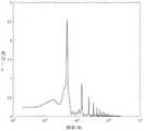
图12B是根据图12A所示脉冲消融信号的频率与脉冲消融信号能量的对应关系图;Fig. 12B is a graph showing the corresponding relationship between the frequency of the pulse ablation signal and the energy of the pulse ablation signal shown in Fig. 12A;
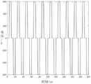
图13A是根据一示例性实施例示出的短脉宽脉冲消融信号的波形图;Fig. 13A is a waveform diagram of a short pulse width pulse ablation signal according to an exemplary embodiment;
图13B是根据图13A所示脉冲消融信号的频率与脉冲消融信号能量的对应关系图;Fig. 13B is a graph showing the correspondence between the frequency of the pulse ablation signal and the energy of the pulse ablation signal shown in Fig. 13A;
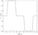
图14是根据一示例性实施例示出的脉冲消融信号的脉宽、电压与肌肉刺激强度的关系图;Fig. 14 is a graph showing the relationship between pulse width, voltage and muscle stimulation intensity of a pulse ablation signal according to an exemplary embodiment;
在以上各个附图中,附图标记的含义如下:In each of the above accompanying drawings, the meanings of the reference signs are as follows:
100、脉冲消融导管,110、远端管体,111,电极,101、第一电极,102、第二电极,103、第三电极;110a、环形圆段,120、末端硬管,130、中间管体,131、主体管,132、柔性可弯段,140、手柄,141、电极插座,142、旋钮;100, pulse ablation catheter, 110, distal tube body, 111, electrode, 101, first electrode, 102, second electrode, 103, third electrode; 110a, annular segment, 120, end hard tube, 130, middle Tube body, 131, main body tube, 132, flexible bendable section, 140, handle, 141, electrode socket, 142, knob;
200、阻抗检测模块,210、第一输出单元,220、第一确定单元;200. Impedance detection module, 210. First output unit, 220. First determination unit;
300、贴靠程度确定模块,310、第二确定单元,320、第三确定单元;300. The abutment degree determination module, 310. The second determination unit, 320. The third determination unit;
400、控制模块;400. Control module;
500、显示组件,510、第一图标,520、第二图标,520a,第一子图标,520b、第二子图标,520c、第三子图标;500. Display component, 510, first icon, 520, second icon, 520a, first sub-icon, 520b, second sub-icon, 520c, third sub-icon;
600、检波装置;600. Wave detection device;
700、肌肉刺激模块,710、监测单元,711、传感器,712、数据采集卡720、第四确定单元;700, muscle stimulation module, 710, monitoring unit, 711, sensor, 712,
800、脉冲能量输出设备。800. Pulse energy output device.
具体实施方式Detailed ways
下面通过实施例的方式进一步说明本发明,但并不因此将本发明限制在所述的实施例范围之中。The present invention is further illustrated below by means of examples, but the present invention is not limited to the scope of the examples.
本发明实施例提供了一种脉冲消融系统,该脉冲消融系统能够判断电极是否与目标组织贴靠到位,以优化脉冲消融治疗效果。图1是根据一示例性实施例示出的脉冲消融导管中电极与目标组织距离对于消融深度的影响关系图。消融电极与消融组织的贴靠程度会对消融效果具有一定的影响。以双极放电为例,在电压、电极、介质相同的情况下,分析消融电极与组织的间距对消融效果的影响,如图1所示,从分析结果可以看到,电极与组织贴靠良好时,其消融效果越好,当电极与组织之间存在间隙时,组织的消融深度随着其间隙的增大而降低,因此,保证导管的远端消融电极与组织的贴靠是很有必要的。An embodiment of the present invention provides a pulse ablation system, which is capable of judging whether an electrode is in close contact with a target tissue, so as to optimize the therapeutic effect of pulse ablation. Fig. 1 is a graph showing the relationship between the distance between an electrode and a target tissue on the ablation depth in a pulse ablation catheter according to an exemplary embodiment. The degree of closeness between the ablation electrode and the ablation tissue will have a certain influence on the ablation effect. Taking bipolar discharge as an example, under the same voltage, electrode, and medium, the influence of the distance between the ablation electrode and the tissue on the ablation effect is analyzed. As shown in Figure 1, it can be seen from the analysis results that the electrode and the tissue are in good contact When the ablation effect is better, when there is a gap between the electrode and the tissue, the ablation depth of the tissue decreases with the increase of the gap. Therefore, it is necessary to ensure the ablation electrode at the distal end of the catheter and the tissue. of.
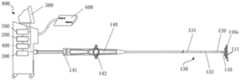
图2是根据一示例性实施例示出的脉冲消融系统的示意图,如图2所示,本发明实施例提供的脉冲消融系统包括脉冲消融导管100、脉冲能量输出设备800和检波装置600。FIG. 2 is a schematic diagram of a pulse ablation system according to an exemplary embodiment. As shown in FIG. 2 , the pulse ablation system provided by the embodiment of the present invention includes a
如图2所示,脉冲消融导管100包括顺次设置的远端管体110、末端硬管120、中间管体130和手柄140。远端管体110的一端为自由端,另一端与末端硬管120连接。在远端管体110远离末端硬管120的部分形成环形圆段110a,环形圆段110a成螺旋状,且在环形圆段110a中远端管体110上设置有电极111。电极111用于接收脉冲消融信号以向目标区域施加消融电场。图3是根据一示例性实施例示出的环形圆段的结构示意图。如图3所示,在远端管体110上设置有多个环状的电极111。可选地,多个电极111通过粘结的方式与远端管体110连接,并等间距地沿远端管体110的轴向分布。其中,电极111的材料可以为铂铱合金、黄金等。远端管体110用于携带电极111进入被消融目标体内的目标组织处,具有高绝缘性、柔韧性和生物相容性,例如采用聚氨酯制备。As shown in FIG. 2 , the
脉冲消融导管100包括内腔,该内腔由手柄140延伸至远端管体110。内腔用于容纳线缆,线缆的一端用于与电极111电性连接,线缆的另一端用于与手柄140上的电极插座141电性连接。脉冲消融导管100在使用时,控制模块400通过与电极插座141电性连接,以通过线缆为电极111提供脉冲消融信号,进而使得电极111产生消融电场以在目标组织处形成病灶。The
此外,中间管体130包括与手柄140连接的主体管131,以及与主体管131和末端硬管120相连的柔性可弯段132。该柔性可弯段132能够朝向不同的方向弯曲。手柄140上还设置有控制件142(例如旋钮),控制件142通过设置在内腔中的牵拉件与柔性可弯段132连接,通过控制键142控制柔性可弯段132朝向期望的方向弯曲,进而调整电极111在被消融目标体内的位置。In addition, the
脉冲能量输出设备800包括阻抗检测模块200、贴靠程度确定模块300、控制模块400和显示组件500。The pulse
控制模块400用于向电极111输出脉冲消融信号,所述脉冲消融信号为高压双相脉冲。图4是根据一示例性实施例示出的脉冲消融信号的波形图。如图4所示,控制模块400向电极111输出高压短脉宽的脉冲波形,输出电压为500~2000V,脉宽0.1~50us。The
显示组件500用于显示交互界面,在交互界面上显示有与每个电极111对应的图标。例如,在交互界面上显示按照周向排列的序号图标,不同序号对应不同的电极111。显示组件500还与控制模块400电性连接,控制模块400响应于检测到对所述图标的触发操作,向与所述图标对应的电极111输出脉冲消融信号,以在所述电极111处形成脉冲电场。The
显示组件500还用于提供设置消融参数的接口,用于接收用户输入的消融参数,以供控制模块400基于所述消融参数生成脉冲消融信号。The
本发明实施例提供的脉冲消融系统能够判断电极111是否与目标组织贴靠到位,在这样的情况下,显示组件500还用于显示电极111与目标组织的贴靠情况,具体在下文结合阻抗检测模块200和贴靠程度确定模块300详细阐述。The pulse ablation system provided by the embodiment of the present invention can judge whether the
检波装置600用于提取被消融目标的心率信号,以确保控制模块400所释放的脉冲消融信号与心率同步。可选地,检波装置600用于检测被消融目标的R波,控制模块400响应于所述检波装置600检测到R波起设定时长(例如20ms~200ms)后释放脉冲消融信号。并且,在控制模块400每次输出脉冲消融信号之后,脉冲消融导管的电极111可以采集ECG信号,控制模块400接收所述ECG信号以确定即刻消融效果。此外,电极111还用于采集心内信号,以进行心内建模和电信号的标测。The
用户在使用脉冲消融导管时,通过在脉冲消融系统配合的三位导航系统或者外部造影系统的辅助下,将脉冲消融导管递送至被消融目标体内的目标组织处。通过显示组件500触发不同的电极图标,使得控制组件300控制电路连通相应电极111,保证所述电极111能够接收脉冲消融信号。进而,响应于脉冲消融触发操作,控制组件300向电极111发送脉冲消融信号,以在目标组织处产生消融电场。在消融过程中,脉冲消融系统还会实时监测电路中的电压、电流、以及电极间的阻抗,以确保脉冲能量的稳定输出;当监测值超出预设的阈值时,立即报警提示,并切断脉冲消融能量的释放,即停止消融。When using the pulse ablation catheter, the user delivers the pulse ablation catheter to the target tissue in the target body to be ablated with the assistance of a three-dimensional navigation system coordinated with the pulse ablation system or an external imaging system. By triggering different electrode icons through the
在本发明实施例中,脉冲消融系统设置有阻抗检测模块200和贴靠程度确定模块300,通过这两个模块能够确定电极111与目标组织的贴靠程度,进而指导用户进行电极位置或者消融参数的调整。In the embodiment of the present invention, the pulse ablation system is provided with an
具体来说,阻抗检测模块200与脉冲消融导管100的电极111电性连接,可选地,阻抗检测模块200通过电极插口141和内腔中的数据线与电极111电性连接,用于向电极111输出测试信号以获取被消融目标的基础阻抗和电极当前所处环境的接触阻抗。具体来说,测试信号为电流信号,接收测试信号的电极对与目标组织和目标组织周围的血液形成回路。此时,通过电压除以测试信号的电流值获取基础阻抗或接触阻抗。Specifically, the
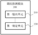
图5是根据一示例性实施例示出的阻抗检测模块的框图。如图5所示,阻抗检测模块200包括第一输出单元210和第一确定单元220。第一输出单元210用于向两个电极所成电极对输出所述测试信号。第一确定单元220用于获取所述电极对基于测试信号产生的电压,并根据所述测试信号和所述电压确定基础阻抗或接触阻抗。基础阻抗是指当电极悬空置于被消融目标的血液中时所获取的阻抗值,接触阻抗是指电极与目标组织接触时所获取的阻抗值。Fig. 5 is a block diagram of an impedance detection module according to an exemplary embodiment. As shown in FIG. 5 , the
图6A和图6B是根据一示例性实施例示出的电极置于不同位置的示意图。如图6A所示,脉冲消融导管100的环形圆段110a悬空置于被消融目标的血液中,例如,在外部导航辅助下,脉冲消融导管的环形圆段110a置于左心房中。此时电极111不接触被消融目标的组织,在这样的情况下,阻抗检测模块200与电极111配合能够获取被消融目标的基础阻抗。Fig. 6A and Fig. 6B are schematic diagrams showing electrodes placed in different positions according to an exemplary embodiment. As shown in FIG. 6A , the
如图6B所示,脉冲消融导管100的环形圆段110a置于目标组织(例如)处。例如,以左上肺静脉(LSPV)为目标组织,在外部导航辅助下,脉冲消融导管的环形圆段110a置于LSPV处,此时电极111接触LSPV处的组织。在这样的情况下,阻抗检测模块200与电极111配合能够获取接触阻抗值。As shown in FIG. 6B, the
结合图3所示,在检测接触阻抗时,任意选择两个电极111形成电极对。为了对不同的电极111进行区分,沿远端管体110的轴向电极111依次命名为第一电极101、第二电极102、第三电极103。检测接触阻抗时,可以选择多个电极111中的任意两个作为电极对,例如将第一电极101和第二电极102作为一组电极对,或者,将第一电极101和第三电极103作为一组电极对。需要说明的是,不同的电极对组合所对应的基础阻抗不同,在本发明实施例中,阻抗检测模组200针对同一组电极对获取基础阻抗和接触阻抗。As shown in FIG. 3 , when detecting the contact impedance, two
再次参照图2,贴靠程度确定模块300与阻抗检测模块200电性连接,用于根据基础阻抗和接触阻抗确定电极与目标组织的贴靠程度。图7是根据一示例性实施例示出的贴靠程度确定模块的框图。如图7所示,贴靠程度确定模块300包括第二确定单元310和第三确定单元320。第二确定单元310用于确定接触阻抗和基础阻抗的差值。第三确定单元320用于根据差值和预设阈值,确定电极与目标组织的贴靠程度。Referring again to FIG. 2 , the adhering
由于心肌组织的阻抗比血液的阻抗高,因此若电极与目标组织相接触,则根据所述电极对获取的接触阻抗与基础阻抗具有差异。并且,所述差值越大表征电极与目标组织的贴靠情况越好。其中,预设阈值与形成电极对的两个电极的相对位置相关。以相邻两个电极形成电极对为例,计差值Re为:Since the impedance of myocardial tissue is higher than that of blood, if the electrodes are in contact with the target tissue, the contact impedance obtained from the electrode pair is different from the basic impedance. Moreover, the larger the difference, the better the adhesion between the electrode and the target tissue. Wherein, the preset threshold is related to the relative positions of the two electrodes forming the electrode pair. Taking two adjacent electrodes forming an electrode pair as an example, the calculated difference Re is:

若所述差值大于或者等于0,且小于或者等于10%,表明所述电极对位于血液中,也即与目标组织贴靠程度差;若所述差值大于10%,且小于或者等于20%,表明所述电极与目标组织贴靠程度一般;若所述差值大于20%,表明所述电极与目标组织贴靠程度好。If the difference is greater than or equal to 0 and less than or equal to 10%, it indicates that the electrode pair is located in the blood, that is, the degree of adhesion to the target tissue is poor; if the difference is greater than 10% and less than or equal to 20% %, it indicates that the electrode adheres well to the target tissue; if the difference is greater than 20%, it indicates that the electrode adheres well to the target tissue.
结合图3,若选择第一电极101和第三电极103作为电极对参与阻抗检测,则相对应的预设阈值小于第一电极101和第二电极102作为电极参与阻抗检测时所采用的预设阈值,以准确判断电极与目标组织的贴靠程度。3, if the
在一个示例中,一个电极可能与不同的电极组成电极对参与阻抗检测。此时,第二确定单元310具体用于获取该电极所参与的每一组电极对的基础阻抗和接触阻抗的差值。示例地,结合图3,第二电极102与第一电极101组成电极对,以获取第一差值Re1,第二电极102和第三电极103组成电极对,以获取第二差值Re2。In one example, one electrode may form an electrode pair with a different electrode to participate in impedance detection. At this time, the
第三确定单元320具体用于根据第二确定单元310所获取的差值中的最大值和预设阈值确定电极与目标组织的贴靠程度。同样以第二电极102分别与第一电极101和第三电极103组成电极对参与阻抗检测为例,第三确定单元320用于确定第一差值Re1和第二差值Re2中的最大值


在一个示例中,显示组件500还用于显示电极的贴靠情况。继续参照图2,显示组件500与贴靠程度确定模块300电性连接,用于显示贴靠程度确定模块300确定的电极与目标组织的贴靠程度。其中,对于显示组件500的具体显示方式不做限定,例如显示组件500以文字的形式进行显示,或者以差异化图标的形式进行显示。In an example, the
图8是根据一示例性实施例示出的显示界面的示意图。如图8所示,显示组件500显示表征远端管体的第一图标510,以及表征电极的第二图标520。显示组件500根据所确定的贴靠程度,以图标差异化的方式显示出第一子图标520a(表征未与目标组织贴靠的电极)、第二子图标520b(表征贴靠程度一般的电极)、以及第三子图标520c(表征贴靠程度良好的电极)。采用这样的方式,直观地展现电极与目标组织的贴靠情况,据此用户依据显示组件500的显示结果,对远端管体进行移位、旋转等操作,使得环形圈段的电极均与组织具有良好的贴靠,从而保证消融的有效性。Fig. 8 is a schematic diagram showing a display interface according to an exemplary embodiment. As shown in FIG. 8 , the
综上所述,本发明实施例提供的脉冲消融系统,通过配置阻抗检测模块200和贴靠程度确定模块300获取不同电极与目标组织的贴靠程度,从而为脉冲消融治疗提供直观、清晰的指导,以实现电极与目标组织有效贴靠,优化消融效果的目的。In summary, the pulse ablation system provided by the embodiment of the present invention obtains the degree of adhesion between different electrodes and the target tissue by configuring the
在实际应用中,不同的被检体的体内阻抗存在差异,在采用相同脉冲参数的情况下,不同的阻抗同样会影响脉冲消融效果。图9是根据一示例性实施例示出的阻抗值对于消融深度的影响关系图。如图9所示,以双电极放电为例,在电压、电极、脉冲参数相同的情况下,阻抗值增加时,回路中的电流值在减小,相对应的消融深度也有所减小。换言之,在其他消融参数相同的情况下,被检体的体内阻抗影响消融深度。In practical applications, there are differences in the in vivo impedance of different subjects, and in the case of using the same pulse parameters, different impedances will also affect the pulse ablation effect. Fig. 9 is a graph showing the influence of impedance value on ablation depth according to an exemplary embodiment. As shown in Figure 9, taking two-electrode discharge as an example, under the same voltage, electrode, and pulse parameters, when the impedance value increases, the current value in the circuit decreases, and the corresponding ablation depth also decreases. In other words, under the condition that other ablation parameters are the same, the in vivo impedance of the subject affects the ablation depth.
基于这一特点,在本发明实施例中,脉冲消融系统依据接触阻抗体现个体阻抗差异,进而根据接触阻抗制定个体化的脉冲消融参数。继续参照图2,控制模块400与阻抗检测模块200电性连接,用于根据监测到的接触阻抗确定脉冲消融信号。可选地,控制模块400根据接触阻抗确定脉冲消融信号的电压。Based on this feature, in the embodiment of the present invention, the pulse ablation system reflects individual impedance differences according to the contact impedance, and then formulates individualized pulse ablation parameters according to the contact impedance. Continuing to refer to FIG. 2 , the
可选地,脉冲消融信号的电压与被检体的接触阻抗的关系为:

在脉冲消融过程中,脉冲电场会产生电刺激,兴奋神经纤维产生动作电进而引起肌肉收缩。当发生肌肉刺激时,被消融目标身体的抖动可能会导致电极移位,从而影响脉冲消融效果。During the pulse ablation process, the pulsed electric field will generate electrical stimulation, and the excited nerve fibers will generate action electricity to cause muscle contraction. When muscle stimulation occurs, the body shaking of the ablated target may cause the electrode to shift, thereby affecting the pulse ablation effect.
在本发明实施例提供的脉冲消融系统还包含肌肉刺激监测模块,以检测被消融目标的肌肉刺激强度。图10是根据一示例性实施例示出的肌肉刺激监测模块的框图,如图10所示,肌肉刺激监测模块700包括监测单元710和第四确定单元720。监测单元710用于获取被消融目标的基础振幅,以及在脉冲消融过程中被消融目标的肌肉刺激振幅。第四确定单元720用于根据基础振幅和肌肉刺激振幅确定肌肉刺激强度。The pulse ablation system provided in the embodiment of the present invention further includes a muscle stimulation monitoring module to detect the muscle stimulation intensity of the target to be ablated. FIG. 10 is a block diagram of a muscle stimulation monitoring module according to an exemplary embodiment. As shown in FIG. 10 , the muscle
图11是根据一示例性实施例示出的肌肉刺激监测模块的使用状态示意图。具体来说,监测单元710包括传感器711和数据采集卡712,传感器711贴覆在被消融目标的体表(例如胸部或腹部),用于随被消融目标的振动起伏同步运动。可选地,传感器711为加速度传感器、位移传感器或力传感器。数据采集卡712与传感器711电性连接,用于接收传感器711输出的基础振幅数据和肌肉刺激振幅数据。可选地,第四确定单元720为集成设置在数据采集卡712内的数据处理芯片。第四确定单元720通过肌肉刺激振幅与被消融目标的基础振幅确定肌肉刺激强度。Fig. 11 is a schematic view showing the usage state of the muscle stimulation monitoring module according to an exemplary embodiment. Specifically, the
基础振幅为被消融目标呼吸引起的自然振动幅度,肌肉刺激振幅为脉冲能量释放过程中监测得到的肌肉振动幅度。第四确定单元720具体通过肌肉刺激振幅与被消融目标的基础振幅确定肌肉刺激振幅增量,进而根据肌肉刺激振幅增量和预设阈值确定肌肉刺激强度。The base amplitude is the natural vibration amplitude caused by the respiration of the ablated target, and the muscle stimulation amplitude is the muscle vibration amplitude monitored during the pulse energy release process. The fourth determining
可选地,第四确定单元720通过以下方式确定肌肉刺激振幅:Optionally, the

其中,SS是肌肉刺激强度,Wp是肌肉刺激振幅,Wo是基础振幅。Among them, SS is the muscle stimulation intensity, Wp is the muscle stimulation amplitude, and Wo is the base amplitude.
肌肉刺激强度SS越小,表明刺激程度越小。具体来说,当当0<SS<2时,表明当前的刺激程度在可接受范围内;当2≤SS<4时,表明当前刺激程度明显;当SS≥4时,表明当前刺激程度严重。The smaller the muscle stimulation intensity SS, the smaller the stimulation degree. Specifically, when 0<SS<2, it indicates that the current stimulation level is within the acceptable range; when 2≤SS<4, it indicates that the current stimulation level is obvious; when SS≥4, it indicates that the current stimulation level is serious.
此外,第四确定单元720还与显示模组500电性连接,显示模组500用于根据第四确定单元720确定的肌肉刺激强度进行显示,例如实时显示肌肉刺激强度随时间变化的关系图。In addition, the
此外,参照图2,肌肉刺激监测模块700还与控制模块400电性连接,以向控制模块400发送监测到的肌肉刺激强度,进而控制模块400根据肌肉刺激强度确定脉冲消融信号。具体来说,控制模块400具体用于根据肌肉刺激强度确定脉冲消融信号的电压和/或脉宽。In addition, referring to FIG. 2 , the muscle
示例地,当肌肉刺激强度明显或者严重时,可通过降低脉冲消融信号脉宽的方式进行调控。脉冲消融信号的脉宽变化与频率变化具有相关性,通过调整脉冲消融信号的脉宽能够调整脉冲消融信号的频率,从而改变脉冲消融信号对于被消融目标的肌肉刺激强度,以下结合附图进行示意性说明。For example, when the intensity of muscle stimulation is obvious or serious, the pulse width of the ablation signal may be reduced for regulation. The pulse width change of the pulse ablation signal is correlated with the frequency change. By adjusting the pulse width of the pulse ablation signal, the frequency of the pulse ablation signal can be adjusted, thereby changing the muscle stimulation intensity of the pulse ablation signal for the ablated target. sexual description.
图12A是根据一示例性实施例示出的长脉宽脉冲消融信号的波形图,图12B是根据图12A所示脉冲消融信号的频率与脉冲消融信号能量的对应关系图。如图12A和图12B所示,长脉宽的脉冲消融信号中,脉冲消融信号的频率相对集中在103Hz处。图13A是根据一示例性实施例示出的短脉宽脉冲消融信号的波形图,图13B是根据图13A所示脉冲消融信号的频率与脉冲消融信号能量的对应关系图。如图13A和图13B所示,短脉宽的脉冲消融信号中,脉冲消融信号的频率相对集中在104~105Hz处。也即,短脉宽脉冲消融信号较长脉宽脉冲消融信号具有更高的频率含量。因此,通过降低脉冲消融信号的脉宽,能够提高脉冲消融信号的频率,进而减弱脉冲消融电场产生的肌肉刺激。Fig. 12A is a waveform diagram of a long-pulse-width pulse ablation signal according to an exemplary embodiment, and Fig. 12B is a graph showing the corresponding relationship between the frequency of the pulse ablation signal and the energy of the pulse ablation signal shown in Fig. 12A. As shown in FIG. 12A and FIG. 12B , in the pulse ablation signal with long pulse width, the frequency of the pulse ablation signal is relatively concentrated at 103 Hz. Fig. 13A is a waveform diagram of a short-pulse ablation signal according to an exemplary embodiment, and Fig. 13B is a graph showing the corresponding relationship between the frequency of the pulse ablation signal and the energy of the pulse ablation signal shown in Fig. 13A. As shown in FIG. 13A and FIG. 13B , among pulse ablation signals with a short pulse width, the frequencies of the pulse ablation signals are relatively concentrated at 104 -105 Hz. That is, the ablation signal with a short pulse width and a longer pulse width has higher frequency content. Therefore, by reducing the pulse width of the pulse ablation signal, the frequency of the pulse ablation signal can be increased, thereby weakening the muscle stimulation generated by the pulse ablation electric field.
示例地,当肌肉刺激强度明显或者严重时,可通过降低脉冲消融信号电压的方式进行调控。具体来说,在相同脉宽的情况下,脉冲消融信号的电压越高,对应的脉冲能量越高,从而引起的肌肉刺激越严重。因此降低脉冲消融信号电压能够有效改善脉冲电场引起的肌肉刺激。For example, when the intensity of the muscle stimulation is obvious or serious, it can be regulated by reducing the voltage of the pulse ablation signal. Specifically, in the case of the same pulse width, the higher the voltage of the pulse ablation signal, the higher the corresponding pulse energy, thereby causing more severe muscle stimulation. Therefore, reducing the voltage of the pulsed ablation signal can effectively improve the muscle stimulation caused by the pulsed electric field.
可选地,脉冲消融系统还包括存储模块,该存储模块存储了脉冲参数与肌肉刺激强度的对应数据,以形成脉冲参数与肌肉刺激强度对应关系的数据库。图14是根据一示例性实施例示出的脉冲消融信号的脉宽、电压与肌肉刺激强度的关系图,如图14所示,将可接受的肌肉刺激强度作为目标值,基于所述数据库,在不改变脉冲消融信号电压时,获取相应的脉宽范围;或者,在不改变脉冲消融信号脉宽时,获取相应的电压范围,从而根据患者可接受范围的刺激程度快速匹配相应的脉冲参数。Optionally, the pulse ablation system further includes a storage module, which stores data corresponding to pulse parameters and muscle stimulation intensity, so as to form a database of the corresponding relationship between pulse parameters and muscle stimulation intensity. Fig. 14 is a diagram showing the relationship between the pulse width, voltage and muscle stimulation intensity of the pulse ablation signal according to an exemplary embodiment. As shown in Fig. 14, the acceptable muscle stimulation intensity is taken as the target value, based on the database, When the voltage of the pulse ablation signal is not changed, the corresponding pulse width range is obtained; or, when the pulse width of the pulse ablation signal is not changed, the corresponding voltage range is obtained, so as to quickly match the corresponding pulse parameters according to the stimulation degree acceptable to the patient.
综上所述,本发明实施例提供的脉冲消融系统能够通过对被消融目标阻抗检测判断脉冲消融导管上的电极是否贴靠到位,并且量化电极与目标组件的贴靠程度,为脉消融后续治疗提供明确参考。该脉冲消融系统基于被消融目标的阻抗对脉冲消融参数进行特征化设定,针对不同的个体均实现良好的脉冲消融效果。并且,还增加了肌肉刺激监测功能,通过对脉冲能量释放期间进行实时监测,确保被消融目标的肌肉刺激振幅在可接受范围内,从而避免肌肉刺激振动引起体内导管移位,进一步优化脉冲消融治疗效果。To sum up, the pulse ablation system provided by the embodiment of the present invention can judge whether the electrodes on the pulse ablation catheter are in place by detecting the impedance of the ablated target, and quantify the degree of adhesion between the electrodes and the target components, so as to provide the follow-up treatment for pulse ablation. Provide clear references. The pulse ablation system sets characteristic pulse ablation parameters based on the impedance of the ablated target, and achieves good pulse ablation effects for different individuals. In addition, the muscle stimulation monitoring function is also added. Through real-time monitoring during the release of pulse energy, the muscle stimulation amplitude of the target to be ablated is ensured within an acceptable range, thereby avoiding the displacement of the catheter in the body caused by muscle stimulation vibration and further optimizing the pulse ablation treatment. Effect.
虽然以上描述了本发明的具体实施方式,但是本领域的技术人员应当理解,这仅是举例说明,本发明的保护范围是由所附权利要求书限定的。本领域的技术人员在不背离本发明的原理和实质的前提下,可以对这些实施方式做出多种变更或修改,但这些变更和修改均落入本发明的保护范围。Although the specific implementation of the present invention has been described above, those skilled in the art should understand that this is only an example, and the protection scope of the present invention is defined by the appended claims. Those skilled in the art can make various changes or modifications to these embodiments without departing from the principle and essence of the present invention, but these changes and modifications all fall within the protection scope of the present invention.
Claims (10)
Translated fromChinesePriority Applications (1)
| Application Number | Priority Date | Filing Date | Title |
|---|---|---|---|
| CN202211085639.5ACN115349944A (en) | 2022-09-06 | 2022-09-06 | Pulse Ablation System |
Applications Claiming Priority (1)
| Application Number | Priority Date | Filing Date | Title |
|---|---|---|---|
| CN202211085639.5ACN115349944A (en) | 2022-09-06 | 2022-09-06 | Pulse Ablation System |
Publications (1)
| Publication Number | Publication Date |
|---|---|
| CN115349944Atrue CN115349944A (en) | 2022-11-18 |
Family
ID=84006429
Family Applications (1)
| Application Number | Title | Priority Date | Filing Date |
|---|---|---|---|
| CN202211085639.5APendingCN115349944A (en) | 2022-09-06 | 2022-09-06 | Pulse Ablation System |
Country Status (1)
| Country | Link |
|---|---|
| CN (1) | CN115349944A (en) |
Cited By (8)
| Publication number | Priority date | Publication date | Assignee | Title |
|---|---|---|---|---|
| CN115778545A (en)* | 2022-12-22 | 2023-03-14 | 天津市鹰泰利安康医疗科技有限责任公司 | Ablation positioning method and system |
| CN116035693A (en)* | 2023-03-14 | 2023-05-02 | 上海圣达济医疗科技有限公司 | A device for releasing radio frequency energy |
| CN116196081A (en)* | 2023-02-07 | 2023-06-02 | 上海玮启医疗器械有限公司 | Circuit switching system and method for pulse ablation catheter |
| CN116942292A (en)* | 2023-09-18 | 2023-10-27 | 迈得诺医疗科技集团有限公司 | Ablation catheter, ablation device and ablation method thereof |
| CN118615006A (en)* | 2024-07-08 | 2024-09-10 | 西安交通大学 | Implantable human intracavitary pulse ablation system and method |
| CN119423952A (en)* | 2023-07-31 | 2025-02-14 | 上海鸿电医疗科技有限公司 | Radiofrequency ablation catheter and radiofrequency ablation device |
| CN119564186A (en)* | 2024-11-13 | 2025-03-07 | 上海玄宇医疗器械有限公司 | Electrode contact detection method for pulsed electric field ablation system based on support vector machine |
| WO2025185248A1 (en)* | 2024-03-07 | 2025-09-12 | 上海微创电生理医疗科技股份有限公司 | Control method for pulse ablation catheter and pulse ablation catheter |
Citations (7)
| Publication number | Priority date | Publication date | Assignee | Title |
|---|---|---|---|---|
| US6391024B1 (en)* | 1999-06-17 | 2002-05-21 | Cardiac Pacemakers, Inc. | RF ablation apparatus and method having electrode/tissue contact assessment scheme and electrocardiogram filtering |
| CN208274617U (en)* | 2017-09-04 | 2018-12-25 | 四川锦江电子科技有限公司 | A kind of RF ablation and Mapping System of interpolar discharge |
| CN111479497A (en)* | 2017-12-19 | 2020-07-31 | 圣犹达医疗用品心脏病学部门有限公司 | Method for assessing contact between an electrode and tissue using complex impedance measurements |
| CN112438793A (en)* | 2019-08-27 | 2021-03-05 | 伯恩森斯韦伯斯特(以色列)有限责任公司 | Estimation of electrode-tissue contact using a rod electrode and an edge electrode |
| CN113116511A (en)* | 2021-04-16 | 2021-07-16 | 杭州维纳安可医疗科技有限责任公司 | Electric signal output method, device, equipment, system and storage medium |
| CN114711958A (en)* | 2022-03-16 | 2022-07-08 | 苏州艾科脉医疗技术有限公司 | Multipolar ablation device for pulsed electric field |
| CN219147881U (en)* | 2022-09-06 | 2023-06-09 | 上海商阳医疗科技有限公司 | Pulse ablation system |
- 2022
- 2022-09-06CNCN202211085639.5Apatent/CN115349944A/enactivePending
Patent Citations (7)
| Publication number | Priority date | Publication date | Assignee | Title |
|---|---|---|---|---|
| US6391024B1 (en)* | 1999-06-17 | 2002-05-21 | Cardiac Pacemakers, Inc. | RF ablation apparatus and method having electrode/tissue contact assessment scheme and electrocardiogram filtering |
| CN208274617U (en)* | 2017-09-04 | 2018-12-25 | 四川锦江电子科技有限公司 | A kind of RF ablation and Mapping System of interpolar discharge |
| CN111479497A (en)* | 2017-12-19 | 2020-07-31 | 圣犹达医疗用品心脏病学部门有限公司 | Method for assessing contact between an electrode and tissue using complex impedance measurements |
| CN112438793A (en)* | 2019-08-27 | 2021-03-05 | 伯恩森斯韦伯斯特(以色列)有限责任公司 | Estimation of electrode-tissue contact using a rod electrode and an edge electrode |
| CN113116511A (en)* | 2021-04-16 | 2021-07-16 | 杭州维纳安可医疗科技有限责任公司 | Electric signal output method, device, equipment, system and storage medium |
| CN114711958A (en)* | 2022-03-16 | 2022-07-08 | 苏州艾科脉医疗技术有限公司 | Multipolar ablation device for pulsed electric field |
| CN219147881U (en)* | 2022-09-06 | 2023-06-09 | 上海商阳医疗科技有限公司 | Pulse ablation system |
Cited By (11)
| Publication number | Priority date | Publication date | Assignee | Title |
|---|---|---|---|---|
| CN115778545A (en)* | 2022-12-22 | 2023-03-14 | 天津市鹰泰利安康医疗科技有限责任公司 | Ablation positioning method and system |
| CN115778545B (en)* | 2022-12-22 | 2023-11-14 | 天津市鹰泰利安康医疗科技有限责任公司 | Ablation positioning method and system |
| CN116196081A (en)* | 2023-02-07 | 2023-06-02 | 上海玮启医疗器械有限公司 | Circuit switching system and method for pulse ablation catheter |
| CN116196081B (en)* | 2023-02-07 | 2024-02-23 | 上海玮启医疗器械有限公司 | Circuit switching system and method for pulse ablation catheter |
| CN116035693A (en)* | 2023-03-14 | 2023-05-02 | 上海圣达济医疗科技有限公司 | A device for releasing radio frequency energy |
| CN119423952A (en)* | 2023-07-31 | 2025-02-14 | 上海鸿电医疗科技有限公司 | Radiofrequency ablation catheter and radiofrequency ablation device |
| CN116942292A (en)* | 2023-09-18 | 2023-10-27 | 迈得诺医疗科技集团有限公司 | Ablation catheter, ablation device and ablation method thereof |
| CN116942292B (en)* | 2023-09-18 | 2024-01-16 | 迈得诺医疗科技集团有限公司 | Ablation catheter, ablation device and ablation method thereof |
| WO2025185248A1 (en)* | 2024-03-07 | 2025-09-12 | 上海微创电生理医疗科技股份有限公司 | Control method for pulse ablation catheter and pulse ablation catheter |
| CN118615006A (en)* | 2024-07-08 | 2024-09-10 | 西安交通大学 | Implantable human intracavitary pulse ablation system and method |
| CN119564186A (en)* | 2024-11-13 | 2025-03-07 | 上海玄宇医疗器械有限公司 | Electrode contact detection method for pulsed electric field ablation system based on support vector machine |
Similar Documents
| Publication | Publication Date | Title |
|---|---|---|
| CN115349944A (en) | Pulse Ablation System | |
| JP6517277B2 (en) | Real-time feedback of electrode contacts during mapping | |
| EP3831442A1 (en) | Using reversible electroporation on cardiac tissue | |
| US6714806B2 (en) | System and method for determining tissue contact of an implantable medical device within a body | |
| US9724018B2 (en) | Method for monitoring phrenic nerve function | |
| JP6240751B2 (en) | Anatomic mapping system for continuous display of recent heart rate characteristics during real-time or playback electrophysiological data visualization | |
| JP2018509981A (en) | High density mapping and ablation catheter | |
| US10595745B2 (en) | Force sensing catheter with impedance-guided orientation | |
| JP2017520286A (en) | Medical device for mapping heart tissue | |
| EP3841999B1 (en) | Combined cardiac pacing and irreversible electroporation (ire) treatment | |
| EP4137079A1 (en) | Phrenic nerve warning | |
| JP2022013663A (en) | Irreversible electroporation based on the amplitude of the measured bipolar signal Estimating the progress of ablation | |
| CN120379609A (en) | Catheter shape detection for mapping and ablation catheters | |
| EP4279002A1 (en) | Impedance-based ablation index for ire | |
| EP3318210A1 (en) | A monitoring system for ablation of cardiac tissue in close proximity to the av node of the heart and for generating a sensorial alert | |
| CN219147881U (en) | Pulse ablation system | |
| CN113425253B (en) | Pacing-induced electrical activation fractionation | |
| CN115361904A (en) | Method of monitoring a patient for collateral damage to the phrenic nerve during a cardiac ablation procedure | |
| EP4622552A1 (en) | A three-dimensional display of a multi-electrode catheter and signals acquired over time | |
| CN114601468A (en) | Signal and correction processing for anatomical mapping data | |
| WO2016038713A1 (en) | Nerve stimulation device, nerve stimulation system and nerve stimulation method |
Legal Events
| Date | Code | Title | Description |
|---|---|---|---|
| PB01 | Publication | ||
| PB01 | Publication | ||
| SE01 | Entry into force of request for substantive examination | ||
| SE01 | Entry into force of request for substantive examination |